Accton Technology WA6101BACC WLAN Dual Band Access Point User Manual Revised
Accton Technology Corp WLAN Dual Band Access Point Users Manual Revised
UserManual.wiki
>
Accton Technology
>
WA6101BACC User Manual
>
Users Manual Revised
Contents
1.
DoC Statement
2.
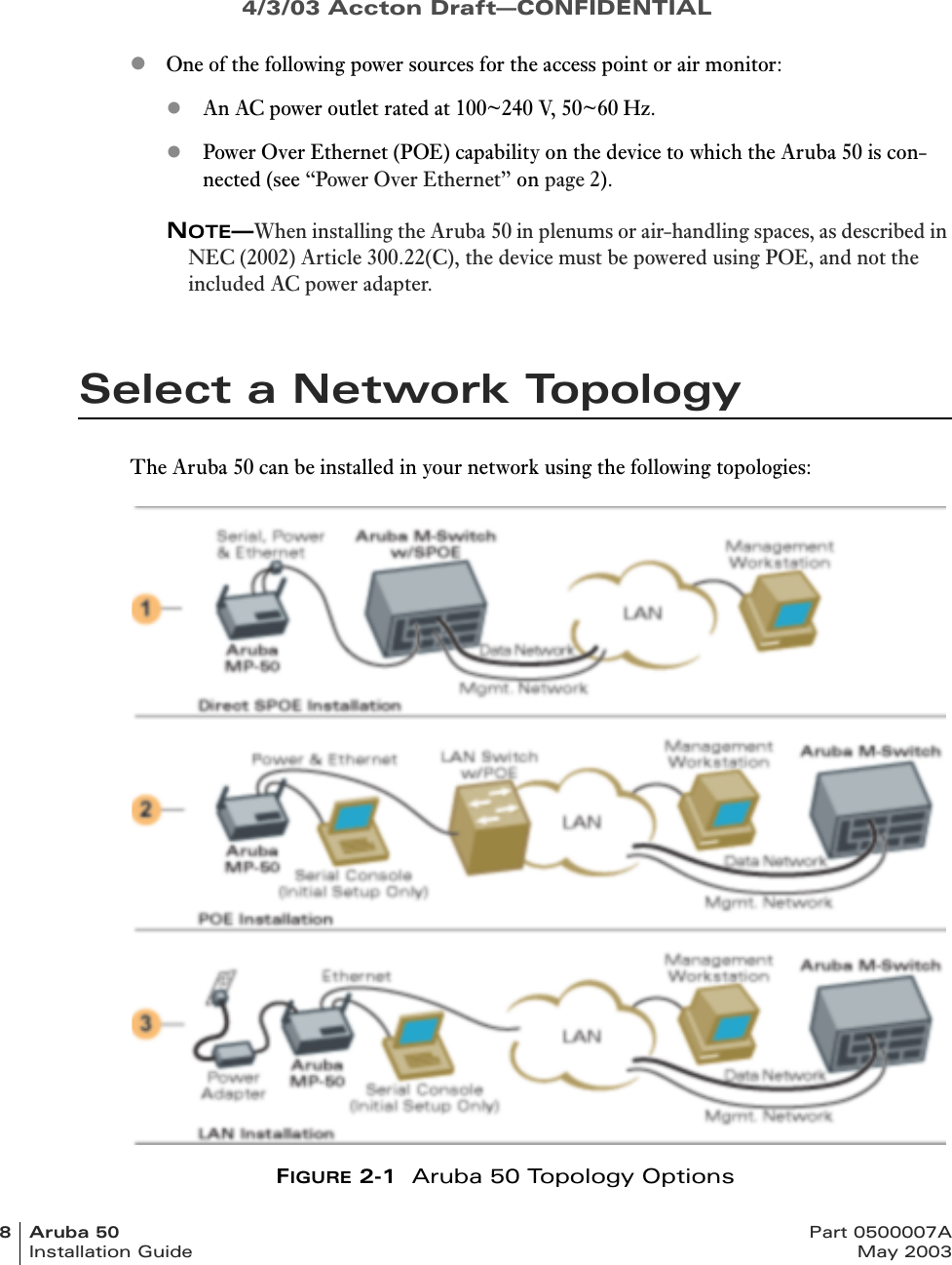
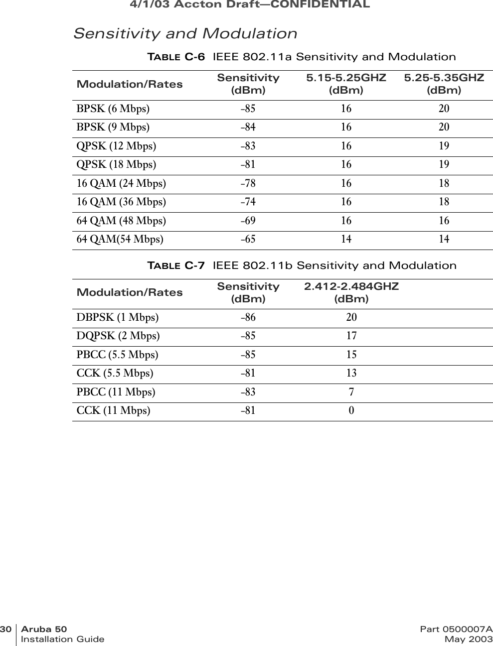
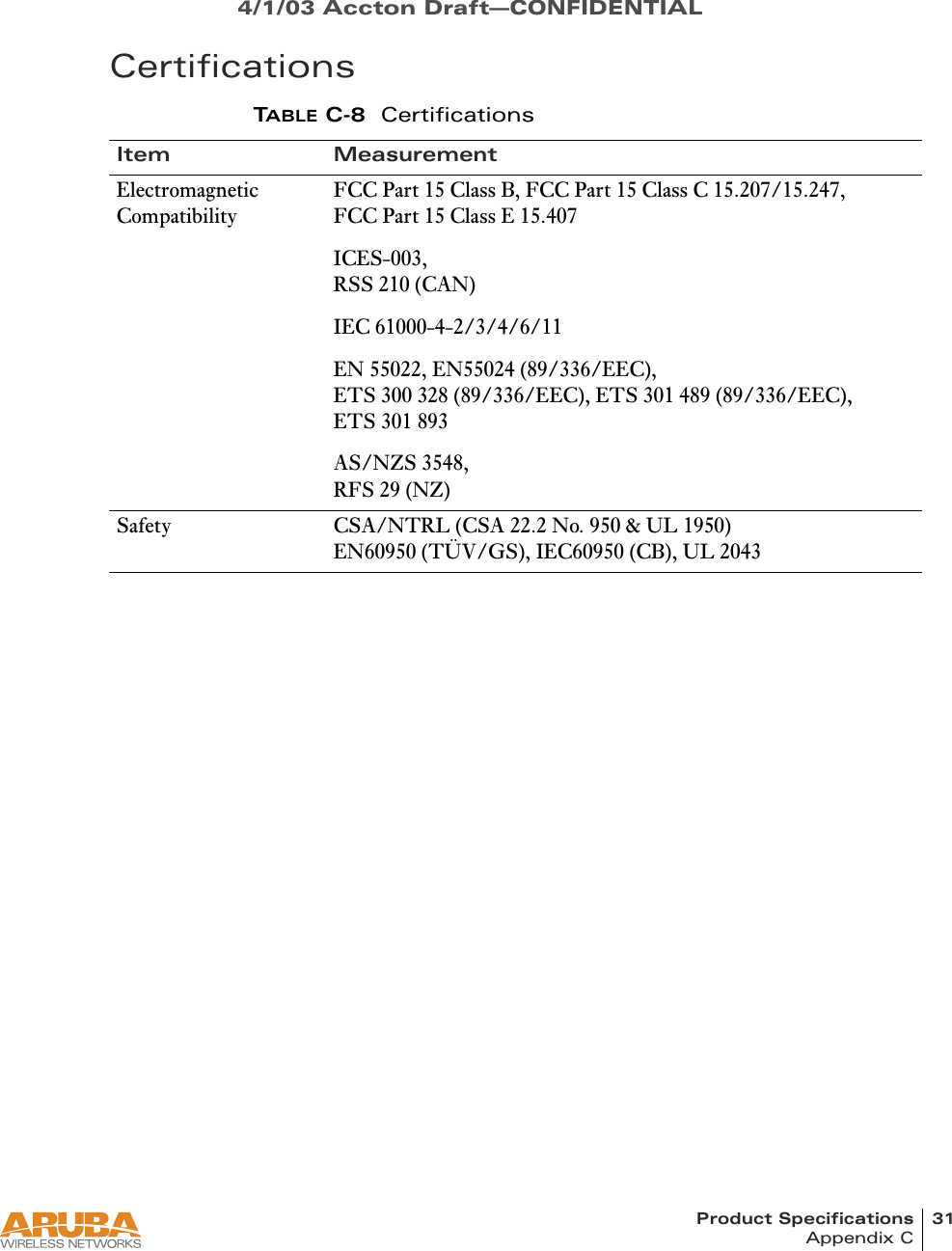
Users Manual Revised
Users Manual Revised
Navigation menu
Upload a User Manual
Namespaces
Wiki Guide
HTML
PDF
Info
Views
User Manual
Discussion / Help
Navigation

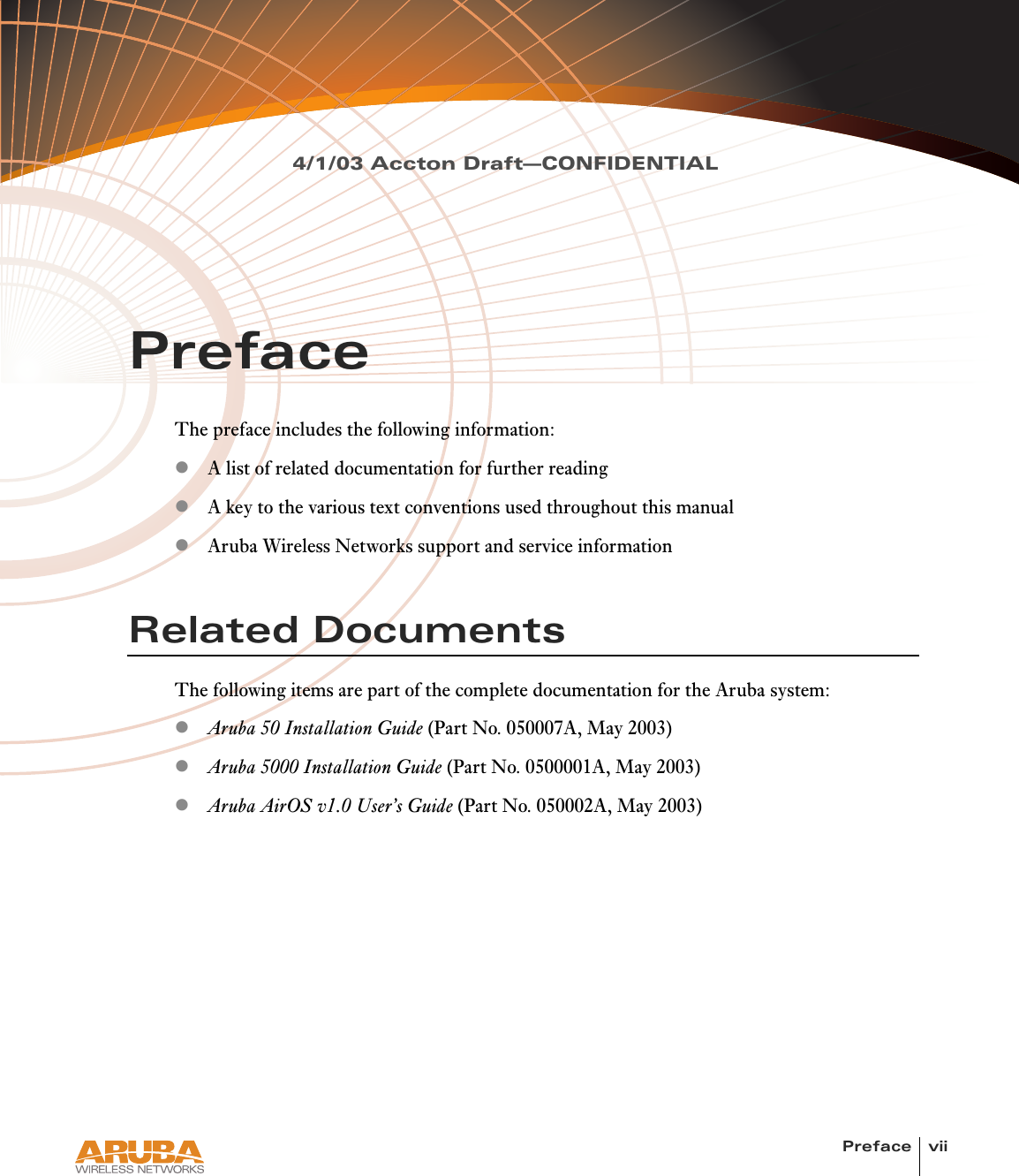
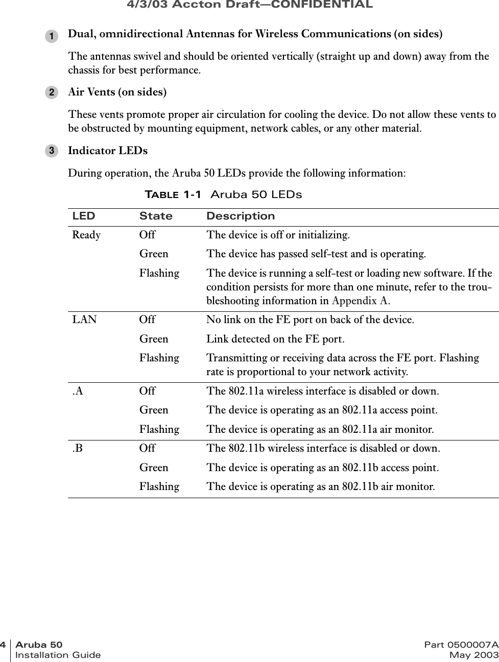
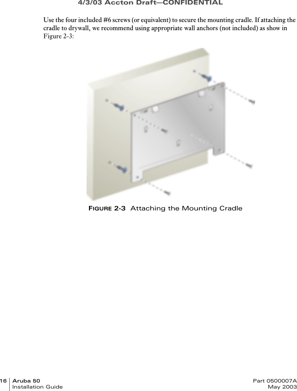
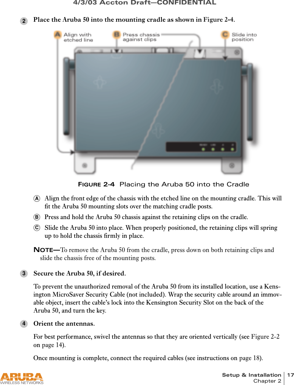
![4/1/03 Accton Draft—CONFIDENTIALviii Aruba 50 Part 0500007AInstallation Guide May 2003Text ConventionsThe following conventions are used throughout this manual to emphasize important concepts:TABLE 1Text ConventionsType Style DescriptionItalics This style is used to emphasize important terms and to mark the titles of books.System items This fixed-width font depicts the following:zSample screen outputzSystem promptszFilenames, software devices, and certain commands when men-tioned in the text.Commands In the command examples, this bold font depicts text that the user must type exactly as shown.<Arguments> In the command examples, italicized text within angle brackets rep-resents items that the user should replace with information appropri-ate to their specific situation. For example:# send <text message>In this example, the user would type “send” at the system prompt exactly as shown, followed by the text of the message they wish to send. Do not type the angle brackets.[ Optional ] In the command examples, items enclosed in brackets are optional. Do not type the brackets.{ Item A | Item B } In the command examples, items within curled braces and separated by a vertical bar represent the available choices. Enter only one choice. Do not type the braces or bars.](https://usermanual.wiki/Accton-Technology/WA6101BACC.Users-Manual-Revised/User-Guide-320226-Page-8.png)