Accton Technology WA6102X WLAN 802.11 a/b/g Access Point User Manual revised manual
Accton Technology Corp WLAN 802.11 a/b/g Access Point revised manual
UserManual.wiki
>
Accton Technology
>
WA6102X User Manual
User Manual
Navigation menu
Upload a User Manual
Namespaces
Wiki Guide
HTML
PDF
Info
Views
User Manual
Discussion / Help
Navigation

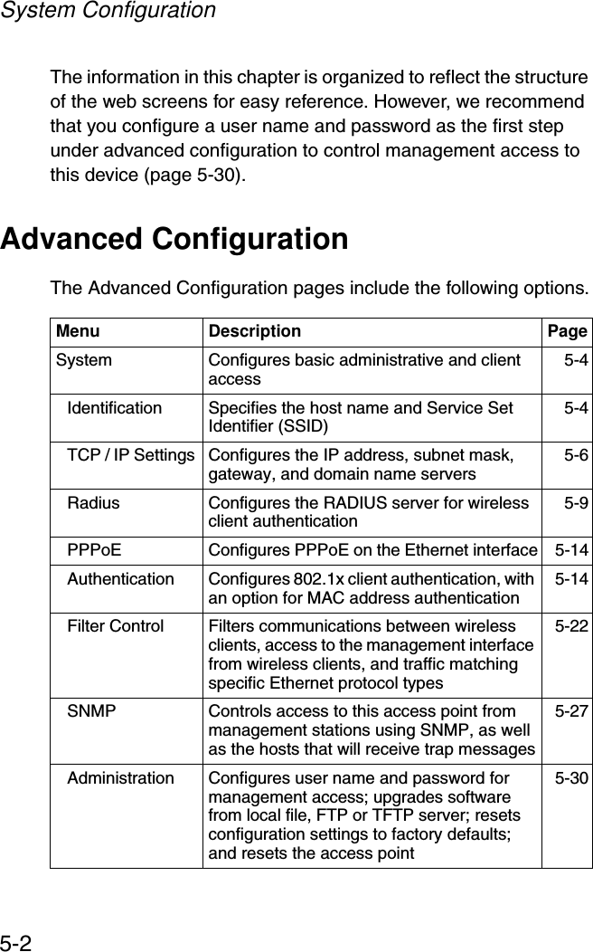
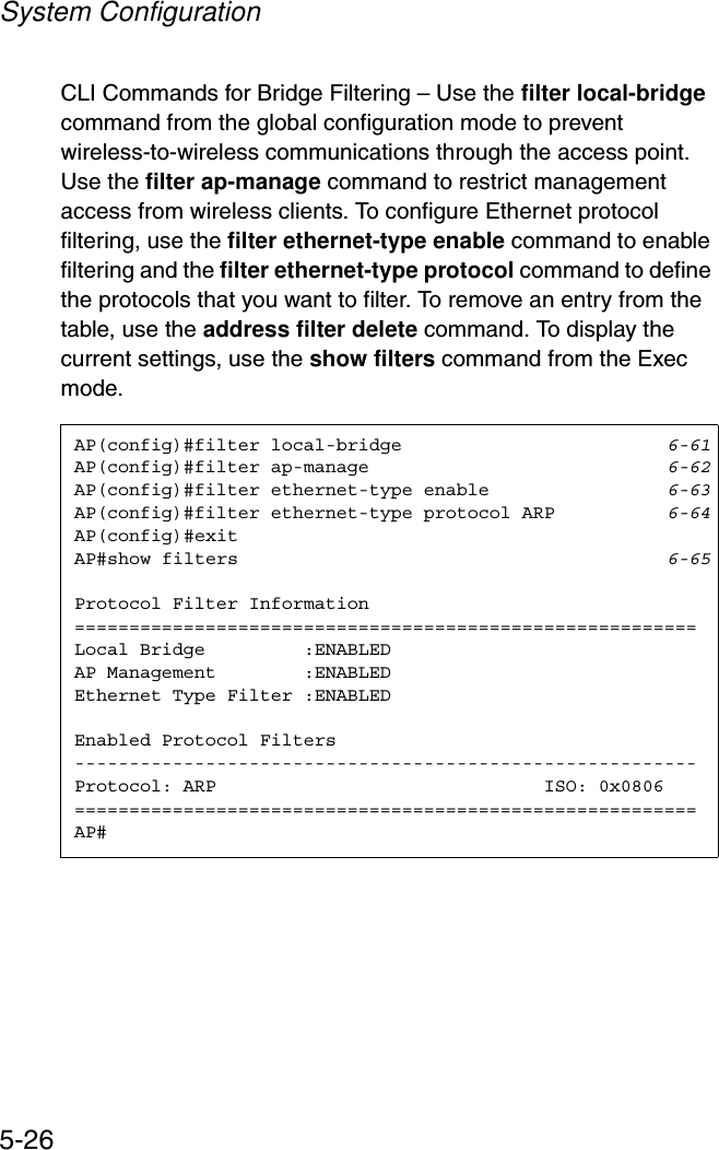
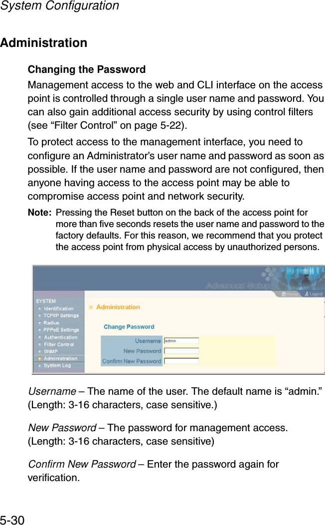
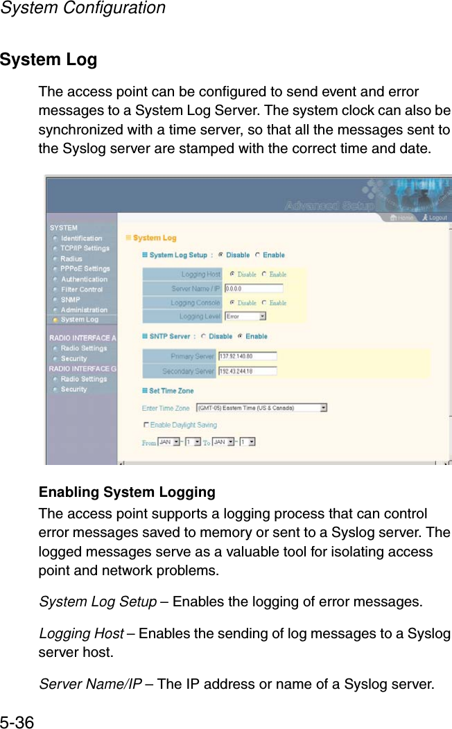
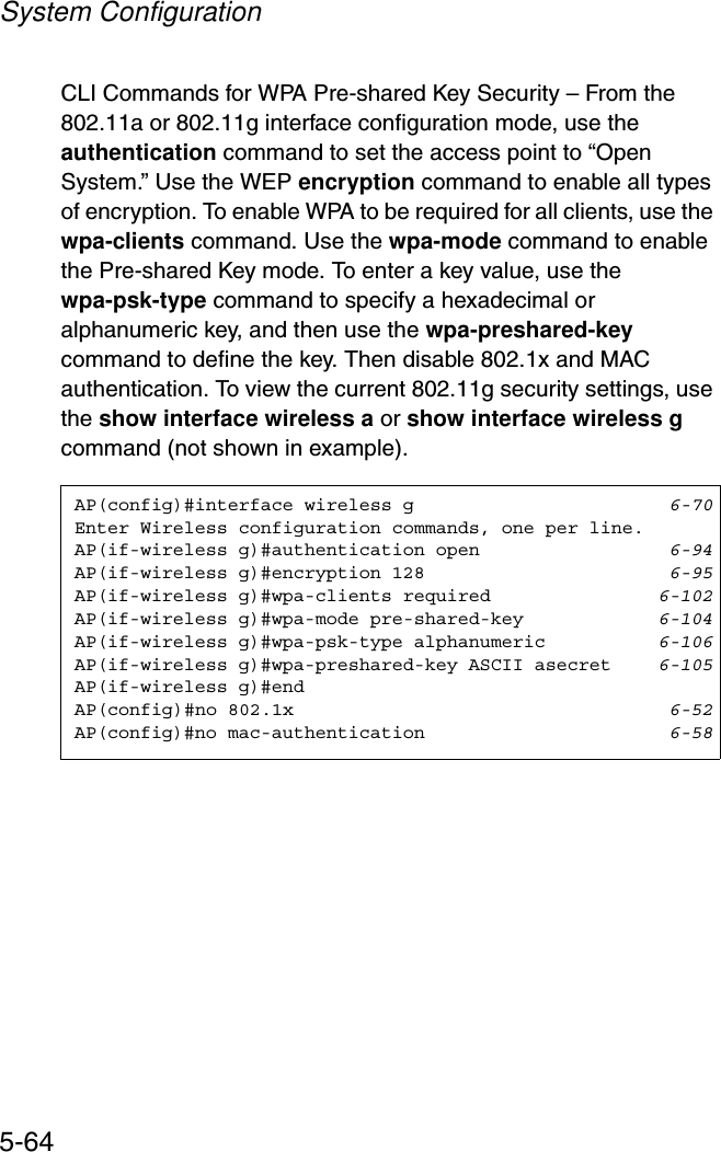
![Advanced Configuration5-35CLI Commands for Downloading Software from a TFTP Server – Use the copy tftp file command from the Exec mode and then specify the file type, name, and IP address of the TFTP server. When the download is complete, the dir command can be used to check that the new file is present in the access point file system. To run the new software, use the reset board command to reboot the access point.AP#copy config tftp 6-42TFTP Source file name:syscfgTFTP Server IP:192.168.1.19AP#AP#copy tftp file 6-421. Application image2. Config file3. Boot block imageSelect the type of download<1,2,3>: [1]:2TFTP Source file name:syscfgTFTP Server IP:10.1.1.9AP#dir 6-44 zz-img.bin 1109148 dflt-img.bin 1101452 ap3xartl.sys 637364 syscfg_bak 16972 syscfg 16972 581632 bytes freeAP#reset board 6-14Reboot system now? <y/n>: yAP#](https://usermanual.wiki/Accton-Technology/WA6102X/User-Guide-481779-Page-70.png)