Accton Technology WA6102X WLAN 802.11 a/b/g Access Point User Manual revised manual
Accton Technology Corp WLAN 802.11 a/b/g Access Point revised manual
User Manual

User Guide
WLAN 11a+b/g Access Point
2.4GHz/5GHz Wireless Access Point
Model: WA6102X / WA6102Y
Accton

User Guide
Guide
2.4GHz/5GHz Wireless Access Point
IEEE 802.11g and 802.11a Dual-band Access Point
with 1 10/100BASE-TX (RJ-45) Port

i
COMPLIANCES
Federal Communication Commission Interference
Statement
This equipment has been tested and found to comply with the limits for a Class B
digital device, pursuant to Part 15 of the FCC Rules. These limits are designed to
provide reasonable protection against harmful interference in a residential
installation. This equipment generates, uses and can radiate radio frequency
energy and, if not installed and used in accordance with the instructions, may
cause harmful interference to radio communications. However, there is no
guarantee that interference will not occur in a particular installation. If this
equipment does cause harmful interference to radio or television reception, which
can be determined by turning the equipment off and on, the user is encouraged to
try to correct the interference by one of the following measures:
• Reorient or relocate the receiving antenna
• Increase the separation between the equipment and receiver
• Connect the equipment into an outlet on a circuit different from that to which the
receiver is connected
• Consult the dealer or an experienced radio/TV technician for help
FCC Caution: Any changes or modifications not expressly approved by the party
responsible for compliance could void the user's authority to operate this
equipment. This device complies with Part 15 of the FCC Rules. Operation is
subject to the following two conditions: (1) This device may not cause harmful
interference, and (2) this device must accept any interference received, including
interference that may cause undesired operation.
IMPORTANT NOTE:
FCC Radiation Exposure Statement
This equipment complies with FCC radiation exposure limits set forth for an
uncontrolled environment. This equipment should be installed and operated with a
minimum distance of 20 centimeters (8 inches) between the radiator and your
body. This transmitter must not be co-located or operating in conjunction with any
other antenna or transmitter.
Wireless 5 GHz Band Statements:
As the Access Point can operate in the 5150-5250 MHz frequency band it is
limited by the FCC, Industry Canada and some other countries to indoor use only
so as to reduce the potential for harmful interference to co-channel Mobile
Satellite systems.

COMPLIANCES
ii
High power radars are allocated as primary users (meaning they have priority) of
the 5250-5350 MHz and 5650-5850 MHz bands. These radars could cause
interference and /or damage to the access point when used in Canada.
The term “IC:” before the radio certification number only signifies that Industry
Canada technical specifications were met.
Industry Canada - Class B
This digital apparatus does not exceed the Class B limits for radio noise emissions
from digital apparatus as set out in the interference-causing equipment standard
entitled “Digital Apparatus,” ICES-003 of Industry Canada.
Cet appareil numérique respecte les limites de bruits radioélectriques applicables
aux appareils numériques de Classe B prescrites dans la norme sur le matérial
brouilleur: “Appareils Numériques,” NMB-003 édictée par l’Industrie.
Safety Compliance
Power Cord Safety
Please read the following safety information carefully before installing the device:
WARNING: Installation and removal of the unit must be carried out by qualified
personnel only.
• The unit must be connected to an earthed (grounded) outlet to comply with
international safety standards.
• Do not connect the unit to an A.C. outlet (power supply) without an earth
(ground) connection.
• The appliance coupler (the connector to the unit and not the wall plug) must have
a configuration for mating with an EN 60320/IEC 320 appliance inlet.
• The socket outlet must be near to the unit and easily accessible. You can only
remove power from the unit by disconnecting the power cord from the outlet.
• This unit operates under SELV (Safety Extra Low Voltage) conditions according
to IEC 60950. The conditions are only maintained if the equipment to which it is
connected also operates under SELV conditions.
France and Peru only
This unit cannot be powered from IT† supplies. If your supplies are of IT type, this
unit must be powered by 230 V (2P+T) via an isolation transformer ratio 1:1, with
the secondary connection point labelled Neutral, connected directly to earth
(ground).
† Impédance à la terre

C
OMPLIANCES
iii
Important! Before making connections, make sure you have the correct cord set.
Check it (read the label on the cable) against the following:
Power Cord Set
U.S.A. and
Canada The cord set must be UL-approved and CSA certified.
The minimum specifications for the flexible cord are:
- No. 18 AWG - not longer than 2 meters, or 16 AWG.
- Type SV or SJ
- 3-conductor
The cord set must have a rated current capacity of at least
10 A
The attachment plug must be an earth-grounding type with
NEMA 5-15P (15 A, 125 V) or NEMA 6-15P (15 A, 250 V)
configuration.
Denmark The supply plug must comply with Section 107-2-D1,
Standard DK2-1a or DK2-5a.
Switzerland The supply plug must comply with SEV/ASE 1011.
U.K. The supply plug must comply with BS1363 (3-pin 13 A) and
be fitted with a 5 A fuse which complies with BS1362.
The mains cord must be <HAR> or <BASEC> marked and
be of type HO3VVF3GO.75 (minimum).
Europe The supply plug must comply with CEE7/7 (“SCHUKO”).
The mains cord must be <HAR> or <BASEC> marked and
be of type HO3VVF3GO.75 (minimum).
IEC-320 receptacle.

COMPLIANCES
iv
Veuillez lire à fond l'information de la sécurité suivante avant
d'installer l’appareil:
AVERTISSEMENT: L’installation et la dépose de ce groupe doivent être confiés à un
personnel qualifié.
• Ne branchez pas votre appareil sur une prise secteur (alimentation électrique)
lorsqu'il n'y a pas de connexion de mise à la terre (mise à la masse).
• Vous devez raccorder ce groupe à une sortie mise à la terre (mise à la masse) afin
de respecter les normes internationales de sécurité.
• Le coupleur d’appareil (le connecteur du groupe et non pas la prise murale) doit
respecter une configuration qui permet un branchement sur une entrée d’appareil
EN 60320/IEC 320.
• La prise secteur doit se trouver à proximité de l’appareil et son accès doit être
facile. Vous ne pouvez mettre l’appareil hors circuit qu’en débranchant son cordon
électrique au niveau de cette prise.
• L’appareil fonctionne à une tension extrêmement basse de sécurité qui est
conforme à la norme IEC 60950. Ces conditions ne sont maintenues que si
l’équipement auquel il est raccordé fonctionne dans les mêmes conditions.
France et Pérou uniquement:
Ce groupe ne peut pas être alimenté par un dispositif à impédance à la terre. Si vos
alimentations sont du type impédance à la terre, ce groupe doit être alimenté par
une tension de 230 V (2 P+T) par le biais d’un transformateur d’isolement à rapport
1:1, avec un point secondaire de connexion portant l’appellation Neutre et avec
raccordement direct à la terre (masse).

C
OMPLIANCES
v
Bitte unbedingt vor dem Einbauen des Geräts die folgenden
Sicherheitsanweisungen durchlesen (Germany):
WARNUNG: Die Installation und der Ausbau des Geräts darf nur durch
Fachpersonal erfolgen.
• Das Gerät sollte nicht an eine ungeerdete Wechselstromsteckdose
angeschlossen werden.
• Das Gerät muß an eine geerdete Steckdose angeschlossen werden, welche die
internationalen Sicherheitsnormen erfüllt.
• Der Gerätestecker (der Anschluß an das Gerät, nicht der
Wandsteckdosenstecker) muß einen gemäß EN 60320/IEC 320 konfigurierten
Geräteeingang haben.
• Die Netzsteckdose muß in der Nähe des Geräts und leicht zugänglich sein. Die
Stromversorgung des Geräts kann nur durch Herausziehen des
Gerätenetzkabels aus der Netzsteckdose unterbrochen werden.
• Der Betrieb dieses Geräts erfolgt unter den SELV-Bedingungen
(Sicherheitskleinstspannung) gemäß IEC 60950. Diese Bedingungen sind nur
gegeben, wenn auch die an das Gerät angeschlossenen Geräte unter
SELV-Bedingungen betrieben werden.
Cordon électrique - Il doit être agréé dans le pays d’utilisation
Etats-Unis et
Canada: Le cordon doit avoir reçu l’homologation des UL et un
certificat de la CSA.
Les spe'cifications minimales pour un cable flexible sont
AWG No. 18, ouAWG No. 16 pour un cable de longueur
infe'rieure a` 2 me'tres.
- type SV ou SJ
- 3 conducteurs
Le cordon doit être en mesure d’acheminer un courant
nominal d’au moins 10 A.
La prise femelle de branchement doit être du type à mise à
la terre (mise à la masse) et respecter la configuration NEMA
5-15P (15 A, 125 V) ou NEMA 6-15P (15 A, 250 V).
Danemark: La prise mâle d’alimentation doit respecter la section 107-2
D1 de la norme DK2 1a ou DK2 5a.
Suisse: La prise mâle d’alimentation doit respecter la norme SEV/
ASE 1011.
Europe La prise secteur doit être conforme aux normes CEE 7/7
(“SCHUKO”)
LE cordon secteur doit porter la mention <HAR> ou
<BASEC> et doit être de type HO3VVF3GO.75 (minimum).

COMPLIANCES
vi
Stromkabel. Dies muss von dem Land, in dem es benutzt wird geprüft werden:
U.S.A und
Canada
Der Cord muß das UL gepruft und war das CSA
beglaubigt.
Das Minimum spezifikation fur der Cord sind:
- Nu. 18 AWG - nicht mehr als 2 meter, oder 16 AWG.
- Der typ SV oder SJ
- 3-Leiter
Der Cord muß haben eine strombelastbarkeit aus
wenigstens 10 A
Dieser Stromstecker muß hat einer erdschluss mit der typ
NEMA 5-15P (15A, 125V) oder NEMA 6-15P (15A, 250V)
konfiguration.
Danemark Dieser Stromstecker muß die ebene 107-2-D1, der
standard DK2-1a oder DK2-5a Bestimmungen einhalten.
Schweiz Dieser Stromstecker muß die SEV/ASE
1011Bestimmungen einhalten.
Europe Das Netzkabel muß vom Typ HO3VVF3GO.75
(Mindestanforderung) sein und die Aufschrift <HAR> oder
<BASEC> tragen.
Der Netzstecker muß die Norm CEE 7/7 erfüllen
(”SCHUKO”).
܅פሽंᘿࢤሽᖲጥᙄऄ!
รԼ二යᆖীڤᎁᢞٽհ܅פ୴᙮ሽᖲΔॺᆖױΔֆΕᇆࢨࠌ!
شृ݁լᖐ۞᧢ޓ᙮ΕףՕפࢨ᧢ޓૠհࢤ֗פ౨Ζ!
รԼ四ය܅פ୴᙮ሽᖲհࠌشլᐙଆڜ٤֗եឫٽऄຏॾΙᆖ࿇!
ڶեឫွழΔᚨمܛೖشΔࠀޏ۟ྤեឫழֱᤉᥛࠌشΖ!
ছႈٽऄຏॾΔਐࠉሽॾࡳ܂ᄐհྤᒵሽॾΖ܅פ୴᙮ሽᖲႊݴ࠹ٽऄຏॾ!
ࢨՠᄐΕઝᖂ֗᠔᛭شሽंᘿ୴ࢤሽᖲໂհեឫΖ!
ڇ6/36H!6/46H᙮փᖙ܂հྤᒵᇷಛႚᙁໂႛᔞ࣍փࠌش
EHU!Tubufnfou;

vii
T
ABLE OF
C
ONTENTS
1 Introduction . . . . . . . . . . . . . . . . . . . . . . . . . . . . . 1-1
Package Checklist . . . . . . . . . . . . . . . . . . . . . . . . . . . . . . . . . 1-2
Hardware Description . . . . . . . . . . . . . . . . . . . . . . . . . . . . . . . 1-3
Component Description . . . . . . . . . . . . . . . . . . . . . . . . . . 1-4
Features and Benefits . . . . . . . . . . . . . . . . . . . . . . . . . . . . . . 1-7
Applications . . . . . . . . . . . . . . . . . . . . . . . . . . . . . . . . . . . . . . 1-8
System Defaults . . . . . . . . . . . . . . . . . . . . . . . . . . . . . . . . . . 1-10
2 Hardware Installation . . . . . . . . . . . . . . . . . . . . . 2-1
3 General Specifications . . . . . . . . . . . . . . . . . . . . . . . . . . .
. . .
Network Topologies . . . . . . . . . . . . . . . . . . . . . . . . . . . . . . . . 3-2
Ad Hoc Wireless LAN (no AP or Bridge) . . . . . . . . . . . . . 3-2
Infrastructure Wireless LAN . . . . . . . . . . . . . . . . . . . . . . . 3-3
Infrastructure Wireless LAN for Roaming Wireless PCs . 3-4
4
General Specifications . . . . . . . . . . . . . . . . . . . . . . . . . . . . . . 4-1
Spec
ifi
cat
i
o
n
s
. . . . . . . . . . . . . . . . . . . . . . . . . . .4-1
5 System Configuration . . . . . . . . . . . . . . . . . . . . . 5-1

1-1
Chapter 1
Introduction
The 2.4GHz/5GHz Wireless Access Point is an IEEE 802.11a/g
access point that provides transparent, wireless high-speed data
communications between a wired LAN and fixed, portable or
mobile devices equipped with an 802.11a, 802.11b or 802.11g
wireless adapter.
This solution offers fast, reliable wireless connectivity with
considerable cost savings over wired LANs (which include
long-term maintenance overhead for cabling). Using 802.11a and
802.11g technology, this access point can easily replace a
10 Mbps Ethernet connection or seamlessly integrate into a 10/
100 Mbps Ethernet LAN.
In addition, the access point offers full network management
capabilities through an easy to configure web interface, a
command line interface for initial configuration and
troubleshooting, and support for Simple Network Management
tools, such as HP’s OpenView.
Radio Characteristics – The IEEE 802.11a/g standard uses a
radio modulation technique known as Orthogonal Frequency
Division Multiplexing (OFDM), and a shared collision domain
(CSMA/CA). It operates at the 5 GHz Unlicensed National
Information Infrastructure (UNII) band for connections to 802.11a
clients, and at 2.4 GHz for connections to 802.11g clients.
IEEE 802.11g includes backward compatibility with the IEEE
802.11b standard. IEEE 802.11b also operates at 2.4 GHz, but
uses Direct Sequence Spread Spectrum (DSSS) modulation
technology to achieve a communication rate of up to 11 Mbps.

Introduction
1-2
The access point supports a 54 Mbps half-duplex connection to
Ethernet networks for each active channel .
Package Checklist
The 2.4GHz/5GHz Wireless Access Point package includes:
•One 2.4GHz/5GHz Wireless Access Point
•One Category 5 network cable
•One RS-232 console cable
•One AC power adapter and power cord
•Four rubber feet
•Three wall-mounting screws
•This User Guide
Inform your dealer if there are any incorrect, missing or damaged
parts. If possible, retain the carton, including the original packing
materials. Use them again to repack the product in case there is a
need to return it.
Hardware Description
1-3
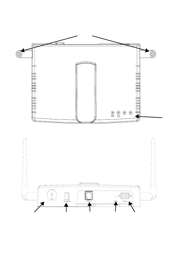
Hardware Description
Top Panel
Rear Panel
WLAN A WLAN G
LED
Indicators
Security Slot RJ-45 Port,
PoE Connector
Reset
Button
Console Port
5 VDC Power
Socket
Antennas

Introduction
1-4
Component Description
Antennas
The access point includes integrated diversity antennas for
wireless communications. A diversity antenna system uses two
identical antennas to receive and transmit signals, helping to
avoid multipath fading effects. When receiving, the access point
checks both antennas and selects the one with the strongest
signal. When transmitting, it will continue to use the antenna
previously selected for receiving. The access point never
transmits from both antennas at the same time.
The antennas transmit the outgoing signal as a toroidal sphere
(doughnut shaped), with the coverage extending most in a
direction perpendicular to the antenna. The antennas should be
adjusted to an angle that provides the appropriate coverage for
the service area. For further information, see “Positioning the
Antennas” on page 2-3.
LED Indicators
The access point includes
four status LED indicators, as
described in the following
figure and table.
LED Status Description
PWR On Indicates that power is being supplied.
Flashing Indicates -
• running a self-test
• loading software program
Flashing
(Prolonged) Indicates system errors
Power 802.11a
Wireless
Link/Activity
Ethernet
Link/Activity 802.11g/b
Wireless
Link/Activity

Hardware Description
1-5
Security Slot
The access point includes a Kensington security slot on the rear
panel. You can prevent unauthorized removal of the access point
by wrapping the Kensington security cable (not provided) around
an unmovable object, inserting the lock into the slot, and turning
the key.
Ethernet
Link On Indicates a valid 10/100 Mbps Ethernet
cable link.
Flashing Indicates that the access point is
transmitting or receiving data on a
10/100 Mbps Ethernet LAN. Flashing
rate is proportional to network activity.
.11a On Indicates a valid 802.11a wireless link.
Very Slow
Flashing Searching for network association.
Slow
Flashing Associated with network but no activity.
Fast
Flashing Indicates that the access point is
transmitting or receiving data through
wireless links. Flashing rate is
proportional to network activity.
.11g On Indicates a valid 802.11g or 802.11b
wireless link.
Very Slow
Flashing Searching for network association.
Slow
Flashing Associated with network but no activity.
Fast
Flashing Indicates that the access point is
transmitting or receiving data through
wireless links. Flashing rate is
proportional to network activity.
LED Status Description

Introduction
1-6
Console Port
This port is used to connect a console device to the access point
through a serial cable. This connection is described under
“Console Port Pin Assignments” on page B-4. The console device
can be a PC or workstation running a VT-100 terminal emulator,
or a VT-100 terminal.
Ethernet Port
The access point has one 10BASE-T/100BASE-TX RJ-45 port
that can be attached directly to 10BASE-T/100BASE-TX LAN
segments. These segments must conform to the IEEE 802.3 or
802.3u specifications.
This port uses an MDI (i.e., internal straight-through) pin
configuration. You can therefore use straight-through twisted-pair
cable to connect this port to most network interconnection
devices such as a switch or router that provide MDI-X ports.
However, when connecting the access point to a workstation or
other device that does not have MDI-X ports, you must use
crossover twisted-pair cable.
The access point appears as an Ethernet node and performs a
bridging function by moving packets from the wired LAN to
remote workstations on the wireless infrastructure.
Note: The RJ-45 port also supports Power over Ethernet (PoE) based
on the IEEE 802.3af standard. Refer to the description for the
“Power Connector” for information on supplying power to the
access point’s network port from a network device, such as a
switch, that provides Power over Ethernet (PoE).

Features and Benefits
1-7
Reset Button
This button is used to reset the access point or restore the factory
default configuration. If you hold down the button for less than 5
seconds, the access point will perform a hardware reset. If you
hold down the button for 5 seconds or more, any configuration
changes you may have made are removed, and the factory
default configuration is restored to the access point.
Power Connector
The access point does not have a power switch. It is powered on
when connected to the AC power adapter, and the power adapter
is connected to a power source. The access point automatically
adjusts to any voltage between 100-240 volts at 50 or 60 Hz. No
voltage range settings are required.
The access point may also receive Power over Ethernet (PoE)
from a switch or other network device that supplies power over
the network cable based on the IEEE 802.3af standard.
Note that if the access point is connected to a PoE source device
and also connected to a local power source through the AC
power adapter, PoE will be disabled.
Features and Benefits
•Local network connection via 10/100 Mbps Ethernet ports or
54 Mbps wireless interface (supporting up to 128 mobile
users)
•IEEE 802.11a, 802.11b and 802.11g compliant
•Interoperable with multiple vendors based on the
IEEE 802.11f protocol

Introduction
1-8
•Advanced security through 64/128/152-bit Wired Equivalent
Protection (WEP) encryption, IEEE 802.1x port
authentication, Wi-Fi Protected Access (WPA), remote
authentication via RADIUS server, and MAC address filtering
features to protect your sensitive data and authenticate only
authorized users to your network
•Provides seamless roaming within the IEEE 802.11a, 802.11b
and 802.11g WLAN environment
•Scans all available channels and selects the best channel for
each client based on the signal-to-noise ratio
•Allows the country of operation to be set to match regulatory
requirements (for countries outside of the United States)
Applications
Wireless network products offer a high speed, reliable,
cost-effective solution for 10/100 Mbps wireless Ethernet client
access to the network in applications such as:
•Remote access to corporate network information
E-mail, file transfer, and terminal emulation.
•Difficult-to-wire environments
Historical or old buildings, asbestos installations, and open
areas where wiring is difficult to deploy.
•Frequently changing environments
Retailers, manufacturers, and banks that frequently
rearrange the workplace or change location.

Applications
1-9
•Temporary LANs for special projects or peak times
Trade shows, exhibitions and construction sites which need
temporary setup for a short time period. Retailers, airline and
shipping companies that need additional workstations for a
peak period. Auditors who require workgroups at customer
sites.
•Access to databases for mobile workers
Doctors, nurses, retailers, or white-collar workers who need
access to databases while being mobile in a hospital, retail
store, or an office campus.
•SOHO users
SOHO (Small Office and Home Office) users who need easy
and quick installation of a small computer network.

Introduction
1-10
System Defaults
The following table lists some of the access point’s basic system
defaults. To reset the access point defaults, use the CLI
command “reset configuration” from the Exec level prompt.
Feature Parameter Default
Identification System Name MEAP
Administration User Name admin
Password null
General HTTP Server Enabled
HTTP Server Port 80
TCP/IP DHCP Enabled
IP Address 192.168.1.1
Subnet Mask 255.255.255.0
Default Gateway 0.0.0.0
Primary DNS IP 0.0.0.0
Secondary DNS IP 0.0.0.0
RADIUS
(Primary and
Secondary)
IP Address 0.0.0.0
Port 1812
Key DEFAULT
Timeout 5 seconds
Retransmit attempts 3

System Defaults
1-11
MAC
Authentication MAC Local MAC
Authentication
Session Timeout
0 seconds (Disabled)
Local MAC
System Default
Allowed
Local MAC
Permission
Allowed
802.1x
Authentication Status Disabled
Broadcast Key
Refresh 0 minutes (Disabled)
Session Key Refresh 0 minutes (Disabled)
Reauthentication
Refresh Rate 0 seconds (Disabled)
VLAN Native VLAN ID 1
VLAN Tag Support Disabled
Filter Control Local Bridge Disabled
Local Management Disabled
Ethernet Type Disabled
SNMP Status Enabled
Location null
Contact Contact
Community
(Read Only) public
Community
(Read/Write) private
Traps Enabled
Trap Destination
IP Address null
Trap Destination
Community Name public
Feature Parameter Default

Introduction
1-12
System
Logging
Syslog Disabled
Logging Host Disabled
Logging Console Disabled
IP Address / Host
Name
0.0.0.0
Logging Level Informational
Logging Facility Type 16
Ethernet
Interface
Speed and Duplex Auto
Wireless
Interface
802.11a
IAPP Enabled
SSID MEAP
Turbo Mode Disabled
Status Enabled
Auto Channel Select Enabled
Closed System Disabled
Transmit Power Full
Maximum Data Rate 108 Mbps
Beacon Interval 100 TUs
Data Beacon Rate
(DTIM Interval) 2 beacons
RTS Threshold 2347 bytes
Feature Parameter Default

System Defaults
1-13
Wireless
Security
802.11a
Authentication Type Open System
WEP Encryption Disabled
WEP Key Length 128 bits
WEP Key Type Hexadecimal
WEP Transmit Key
Number
1
WEP Keys null
WPA Configuration
Mode
All clients
WPA Key
Management
WPA authentication
over 802.1x
Multicast Cipher WEP
Wireless
Interface
802.11b/g
IAPP Enabled
SSID MEAP
Status Enabled
Auto Channel Select Enabled
Closed System Disabled
Transmit Power Full
Maximum Data Rate 108 Mbps
Beacon Interval 100 TUs
Data Beacon Rate
(DTIM Interval)
2 beacons
RTS Threshold 2347 bytes
Feature Parameter Default
Turbo Mode Disabled

Introduction
1-14
Wireless
Security
802.11b/g
Authentication Type Open System
WEP Encryption Disabled
WEP Key Length 128 bits
WEP Key Type Hexadecimal
WEP Transmit Key
Number 1
WEP Keys null
WPA Configuration
Mode All clients
WPA Key
Management WPA authentication
over 802.1x
Multicast Cipher WEP
Feature Parameter Default

2-1
Chapter 2
Hardware Installation
1. Select a Site – Choose a proper place for the access point. In
general, the best location is at the center of your wireless
coverage area, within line of sight of all wireless devices. Try
to place the access point in a position that can best cover its
Basic Service Set (refer to “Infrastructure Wireless LAN” on
page 3-3). For optimum performance, consider these points:
• Mount the access point as high as possible above any
obstructions in the coverage area
• Avoid mounting next to or near building support columns
or other obstructions that may cause reduced signal or
null zones in parts of the coverage area
• Mount away from any signal absorbing or reflecting
structures (such as those containing metal)
2. Mount the Access Point – The access point can be mounted
on any horizontal surface or wall.
Mounting on a horizontal surface – To keep the access point
from sliding on the surface, attach the four rubber feet
provided in the accessory kit to the embossed circles on the
bottom of the access point.
Mounting on a wall – The access point should be mounted
only to a wall or wood surface that is at least 1/2-inch plywood
or its equivalent. Mark the position of the mounting screws
(included) on the wall. Set the 5/8-inch number 12 wood
screws into the wall, leaving about 3 mm (0.12 in.) clearance
from the wall. And then slide the access point down onto the
screws.

Hardware Installation
2-2
3. Lock the Access Point in Place – To prevent unauthorized
removal of the access point, you can use a Kensington Slim
MicroSaver security cable (not included) to attach the access
point to a fixed object.
4. Connect the Power Cord – Connect the power adapter to
the access point, and the power cord to an AC power outlet.
Otherwise, the access point can derive its operating power
directly from the RJ-45 port when connected to a device that
provides IEEE 802.3af compliant Power over Ethernet (PoE).
Note: If the access point is connected to both a PoE source device
and an AC power source, PoE will be disabled.
Warning: Use ONLY the power adapter supplied with this access
point. Otherwise, the product may be damaged.
5. Observe the Self Test – When you power on the access
point, verify that the PWR indicator stops flashing and
remains on, and that the other indicators start functioning as
described under “LED Indicators” on page 1-4.
If the PWR LED does not stop flashing, the self test has not
completed correctly. Refer to “Troubleshooting” on page A-1.

Hardware Installation
2-3
6. Connect the Ethernet Cable – The access point can be
wired to a 10/100 Mbps Ethernet through a network device
such as a hub or a switch. Connect your network to the RJ-45
port on the back panel with category 3, 4, or 5 UTP Ethernet
cable. When the access point and the connected device are
powered on, the Ethernet Link LED should light indicating a
valid network connection.
Note: The RJ-45 port on the access point uses an MDI pin
configuration, so you must use straight-through cable for
network connections to hubs or switches that only have
MDI-X ports, and crossover cable for network connections to
PCs, servers or other end nodes that only have MDI ports.
However, if the device to which you are connecting supports
auto-MDI/MDI-X operation, you can use either
straight-through or crossover cable.
7. Position the Antennas – Each antenna emits a radiation
pattern that is a toroidal sphere (doughnut shaped), with the
coverage extending most in the direction perpendicular to the
antenna. Therefore, the antennas should be oriented so that
the radio coverage pattern fills the intended horizontal space.
Also, the diversity antennas should both be positioned along
the same axes, providing the same coverage area. For
example, if the access point is mounted on a horizontal
surface, both antennas should be positioned pointing
vertically up to provide optimum coverage.
8. Connect the Console Port – Connect the console cable
(included) to the RS-232 console port for accessing the
command-line interface. You can manage the access point
using the console port (Chapter 6), the web interface
(Chapter 5), or SNMP management software such as HP’s
OpenView.

Hardware Installation
2-4

3-1
Chapter 3
Network Configuration
The wireless solution supports a stand-alone wireless network
configuration as well as an integrated configuration with
10/100 Mbps Ethernet LANs.
Wireless network cards, adapters, and access points can be
configured as:
•Ad hoc for departmental, SOHO or enterprise LANs
•Infrastructure for wireless LANs
•Infrastructure wireless LAN for roaming wireless PCs
The 802.11b and 802.11g frequency band which operates at
2.4 GHz can easily encounter interference from other 2.4 GHz
devices, such as other 802.11b or g wireless devices, cordless
phones and microwave ovens. If you experience poor wireless
LAN performance, try the following measures:
•Limit any possible sources of radio interference within the
service area
•Increase the distance between neighboring access points
•Decrease the signal strength of neighboring access points
•Increase the channel separation of neighboring access points
(e.g. up to 3 channels of separation for 802.11b, or up to 4
channels for 802.11a, or up to 5 channels for 802.11g)
Network Configuration
3-2
Network Topologies
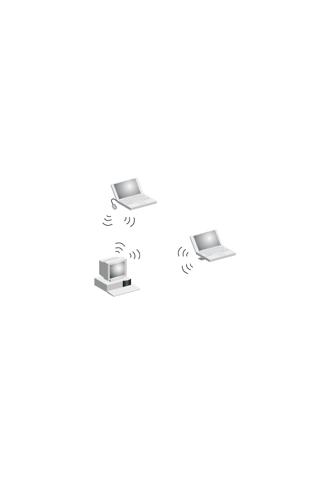
Ad Hoc Wireless LAN (no AP or Bridge)
An ad hoc wireless LAN consists of a group of computers, each
equipped with a wireless adapter, connected via radio signals as
an independent wireless LAN. Computers in a specific ad hoc
wireless LAN must therefore be configured to the same radio
channel. An ad hoc wireless LAN can be used for a branch office
or SOHO operation.
Ad Hoc Wireless LAN
Notebook with
Wireless USB Adapter
Notebook with
Wireless PC Card
PC with Wireless
PCI Adapter
Network Topologies
3-3
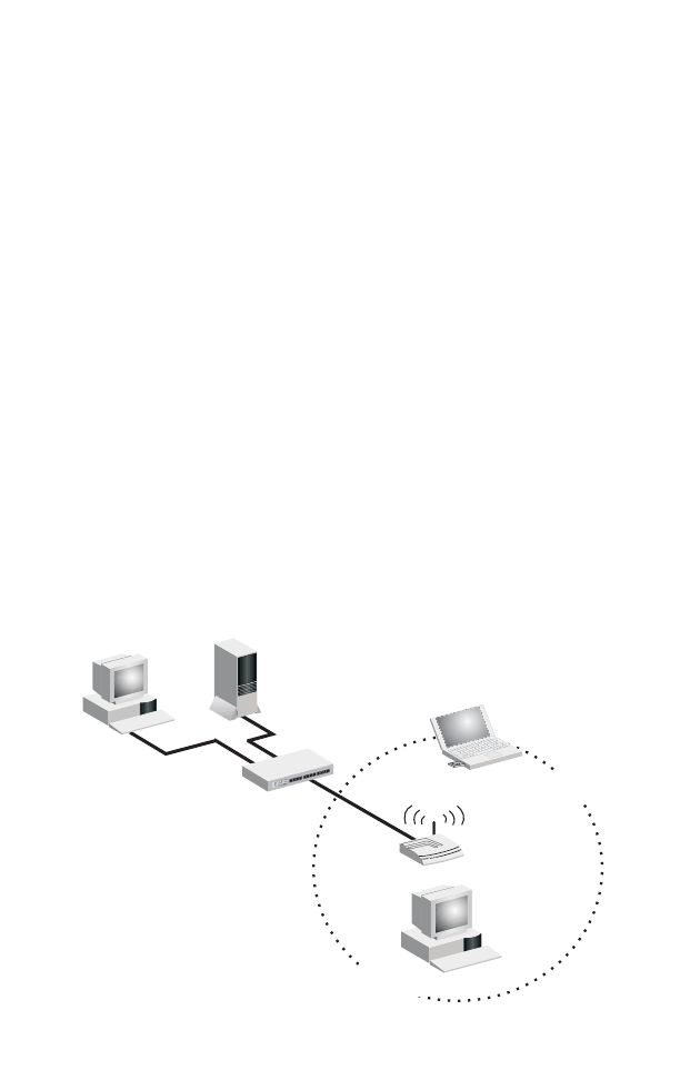
Infrastructure Wireless LAN
The access point also provides access to a wired LAN for
wireless workstations. An integrated wired/wireless LAN is called
an Infrastructure configuration. A Basic Service Set (BSS)
consists of a group of wireless PC users, and an access point
that is directly connected to the wired LAN. Each wireless PC in
this BSS can talk to any computer in its wireless group via a radio
link, or access other computers or network resources in the wired
LAN infrastructure via the access point.
The infrastructure configuration not only extends the accessibility
of wireless PCs to the wired LAN, but also increases the effective
wireless transmission range for wireless PCs by passing their
signal through one or more access points.
A wireless infrastructure can be used for access to a central
database, or for connection between mobile workers, as shown in
the following figure.
File
Server
Switch
Desktop PC
Access Point
Wired LAN Extension
to Wireless Adapters
PC with Wireless
PCI Adapter
Notebook with Wireless
PC Card Adapter

Network Configuration
3-4
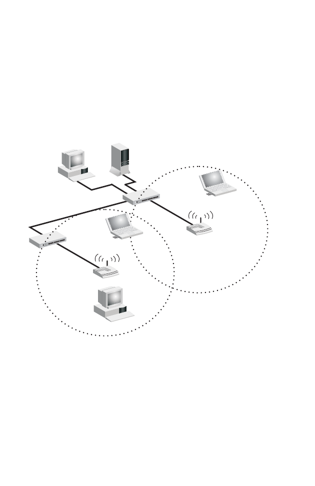
Infrastructure Wireless LAN for Roaming Wireless PCs
The Basic Service Set (BSS) defines the communications domain
for each access point and its associated wireless clients. The
BSS ID is a 48-bit binary number based on the access point’s
wireless MAC address, and is set automatically and transparently
as clients associate with the access point. The BSS ID is used in
frames sent between the access point and its clients to identify
traffic in the service area.
The BSS ID is only set by the access point, never by its clients.
The clients only need to set the Service Set Identifier (SSID) that
identifies the service set provided by one or more access points.
The SSID can be manually configured by the clients, can be
detected in an access point’s beacon, or can be obtained by
querying for the identity of the nearest access point. For clients
that do not need to roam, set the SSID for the wireless card to
that used by the access point to which you want to connect.
Network Topologies
3-5
A wireless infrastructure can also support roaming for mobile
workers. More than one access point can be configured to create
an Extended Service Set (ESS). By placing the access points so
that a continuous coverage area is created, wireless users within
this ESS can roam freely. All wireless network cards and adapters
and wireless access points within a specific ESS must be
configured with the same SSID.
File
Server
Switch
Desktop PC
Access Point <BSS2>
Notebook with Wireless
PC Card Adapter
Seamless Roaming
<ESS>
Switch
Access Point
<BSS1>
PC with Wireless
PCI Adapter
Notebook with Wireless
PC Card Adapter

4-1
Chapter 4 Specifications
General Specifications
Maximum Channels
802.11a:
US & Canada: 13 (normal mode), 5 (turbo mode)
Japan: 4 (normal mode), 1 (turbo mode)
ETSI: 11 channels (normal mode), 4 (turbo mode)
Taiwan: 8 (normal mode), 3 (turbo mode)
802.11b/g:
FCC/IC: 1-11,1 (turbo mode) , ETSI: 1-13, France: 10-13, MKK: 1-14
Taiwan: 1-11, 1 (turbo mode)
Maximum Clients
64 per radio
Operating Range
See “Maximum Distance Table” on page A-4
Data Rate
802.11a:
Normal Mode: 6, 9, 12, 18, 24, 36, 48, 54 Mbps per channel
Turbo Mode: 12, 18, 24, 36, 48, 54, 96, 108 Mbps per channel
802.11g: 6, 9, 11, 12, 18, 24, 36, 48, 54 Mbps per channel
Turbo Mode: up to 108Mbps
Modulation Type
802.11a: BPSK, QPSK, 16-QAM, 64-QAM
802.11g: CCK, BPSK, QPSK, OFDM
802.11b: CCK, BPSK, QPSK
80
2.11
b
: 1
,
2
,
5
.
5,
11 M
bps
pe
r
c
h
a
nn
e
l

Specifications
4-2
Network Configuration
Infrastructure
Operating Frequency
802.11a:
5.15 ~ 5.25 GHz (lower band) US/Canada, Japan
5.25 ~ 5.35 GHz (middle band) US/Canada
5.725 ~ 5.825 GHz (upper band) US/Canada
5.50 ~ 5.70 GHz Europe
5.25 ~ 5.35 GHz (middle band) Taiwan
5.725 ~ 5.825 GHz (high band) Taiwan
802.11b:
2.4 ~ 2.4835 GHz (US, Canada, ETSI)
2.4 ~ 2.497 GHz (Japan)
2.400 ~ 2.4835 GHz ,(Taiwan)
AC Power Adapter
Input: 100-240 AC, 50-60 Hz
Output: 5 VDC, 3 A
Maximum Power: 13.2 W
Unit Power supply
DC Input: 5 VDC, 1.92 A maximum
PoE input: -48 VDC, 0.2 A maximum
Power consumption: 9.6 W maximum
Note: Power can also be provided to the access point through the
Ethernet port based on IEEE 802.3af Power over Ethernet (PoE)
specifications. When both PoE is provided and the adapter is
plugged in, PoE will be turned off.
Physical Size
20.9 x 12.5 x 2.6 cm (8.23 x 4.92 x 1.02 in)
Weight
0.80 kg (1.76 lbs)

General Specifications
4-3
LED Indicators
PWR (Power), Ethernet Link (Ethernet Link/Activity), .11a
and .11g (Wireless Link/Activity)
Network Management
Web-browser, RS232 console, Telnet, SNMP
Temperature
Operating: 0 to 50 °C (32 to 122 °F)
Storage: 0 to 70 °C (32 to 158 °F)
Humidity
15% to 95% (non-condensing)
Compliances
FCC Class B (US)
ICES-003 (Canada)
RTTED 1999/5/EC
VCCI (Japan)
DGT (Taiwan)
Radio Signal Certification
FCC Part 15.247 (2.4GHz)
FCC part 15 15.407(b), CISPR 22-96
RSS-210 (Canada)
EN 300.328, EN 302.893
EN 300 826, EN 301.489-1, EN 301.489-17
ETSI 300.328; ETS 300 826 (802.11b)
MPT RCR std.33 (D66 1~13 Channel, T33 Channel 14)
Safety
CSA/NTRL (CSA 22.2 No. 950 & UL 1950)
EN60950 (TÜV/GS), IEC60950 (CB)
Standards
IEEE 802.3 10BASE-T, IEEE 802.3u 100BASE-TX,
IEEE 802.11a, b, g

5-1
Chapter 5
System Configuration
Before continuing with advanced configuration, first complete the
initial configuration steps described in Chapter 4 to set up an IP
address for the access point.
The access point can be managed by any computer using a web
browser (Internet Explorer 5.0 or above, or Netscape Navigator
6.2 or above). Enter the configured IP address of the access
point, or use the default address:
http://192.168.1.1
To log into the access point, enter the default user name “admin,”
leave the password blank, and click “LOGIN”. When the home
page displays, click on Advanced Setup. The following page will
display.

System Configuration
5-2
The information in this chapter is organized to reflect the structure
of the web screens for easy reference. However, we recommend
that you configure a user name and password as the first step
under advanced configuration to control management access to
this device (page 5-30).
Advanced Configuration
The Advanced Configuration pages include the following options.
Menu Description Page
System Configures basic administrative and client
access 5-4
Identification Specifies the host name and Service Set
Identifier (SSID) 5-4
TCP / IP Settings Configures the IP address, subnet mask,
gateway, and domain name servers 5-6
Radius Configures the RADIUS server for wireless
client authentication 5-9
PPPoE Configures PPPoE on the Ethernet interface 5-14
Authentication Configures 802.1x client authentication, with
an option for MAC address authentication 5-14
Filter Control Filters communications between wireless
clients, access to the management interface
from wireless clients, and traffic matching
specific Ethernet protocol types
5-22
SNMP Controls access to this access point from
management stations using SNMP, as well
as the hosts that will receive trap messages
5-27
Administration Configures user name and password for
management
access; upgrades software
from local file, FTP or TFTP server;
resets
configuration settings to factory defaults;
and resets the access point
5-30

Advanced Configuration
5-3
System Log Controls logging of error messages; sets the
system clock via SNTP server or manual
configuration
5-36
Radio Interface 1 Configures the IEEE 802.11a interface 5-42
Radio Settings Configures radio signal parameters, such as
radio channel, transmission rate, and
beacon settings
5-43
Security Configures data encryption with Wired
Equivalent Protection (WEP) or Wi-Fi
Protected Access (WPA)
5-52
Radio Interface 2 Configures the IEEE 802.11g interface 5-42
Radio Settings Configures radio signal parameters, such as
radio channel, transmission rate, and
beacon settings
5-48
Security Configures data encryption with Wired
Equivalent Protection (WEP) or Wi-Fi
Protected Access (WPA)
5-52
Menu Description Page
System Configuration
5-4
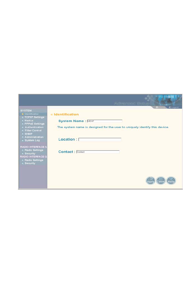
System Identification
The system information parameters for the access point can be
left at their default settings. However, modifying these parameters
can help you to more easily distinguish different devices in your
network.
You should set a Service Set Identification (SSID) to identify the
wireless network service provided by the access point. Only
clients with the same SSID can associate with the access point.
System Name – An alias for the access point, enabling the device
to be uniquely identified on the network. (Default: MEAP; Range:
1-22 characters)
SSID – The name of the basic service set provided by the access
point. Clients that want to connect to the network through the
access point must set their SSID to the same as that of the
access point. (Default: MEAP; Range: 1-32 characters)

Advanced Configuration
5-5
CLI Commands for System Identification – Enter the global
configuration mode, and use the system name command to
specify a new system name. Enter the wireless configuration
mode (either 11a or 11g), and use the ssid command to set the
service set identifier. Then return to the Exec mode, and use the
show system command to display the changes to the system
identification settings.
AP#configure 6-11
AP(config)#system name R&D 6-20
AP(config)#interface wireless a 6-70
AP(if-wireless a)#ssid r&d 6-90
AP(if-wireless a)#end 6-12
AP#show system 6-33
System Information
===================================================
Serial Number : A324003220
System Up time : 0 days, 0 hours, 32 minutes, 51 seconds
System Name : r&d
System Location :
System Contact : Contact
System Country Code : US - UNITED STATES
MAC Address : 00-30-F1-91-91-5B
IP Address : 192.168.2.51
Subnet Mask : 255.255.255.0
Default Gateway : 192.168.2.250
VLAN State : DISABLED
Native VLAN ID : 1
IAPP State : ENABLED
DHCP Client : ENABLED
HTTP Server : ENABLED
HTTP Server Port : 80
Slot Status : Dual band(b/g)
Software Version : v0.0.0.2
===================================================
AP#

System Configuration
5-6
TCP / IP Settings
Configuring the access point with an IP address expands your
ability to manage the access point. A number of access point
features depend on IP addressing to operate.
Note: You can use the web browser interface to access IP addressing
only if the access point already has an IP address that is
reachable through your network.
By default, the access point will be automatically configured with
IP settings from a Dynamic Host Configuration Protocol (DHCP)
server. However, if you are not using a DHCP server to configure
IP addressing, use the CLI to manually configure the initial IP
values (page 4-3). After you have network access to the access
point, you can use the web browser interface to modify the initial
IP configuration, if needed.
Note: If there is no DHCP server on your network, or DHCP fails, the
access point will automatically start up with a default IP address of
192.168.1.1.

Advanced Configuration
5-7
DHCP Client (Enable) – Select this option to obtain the IP
settings for the access point from a DHCP (Dynamic Host
Configuration Protocol) server. The IP address, subnet mask,
default gateway, and Domain Name Server (DNS) address are
dynamically assigned to the access point by the network DHCP
server. (Default: Enabled)
DHCP Client (Disable) – Select this option to manually configure
a static address for the access point.
•IP Address: The IP address of the access point. Valid IP
addresses consist of four decimal numbers, 0 to 255,
separated by periods.
•Subnet Mask: The mask that identifies the host address bits
used for routing to specific subnets.
•Default Gateway: The default gateway is the IP address of the
router for the access point, which is used if the requested
destination address is not on the local subnet.
If you have management stations, DNS, RADIUS, or other
network servers located on another subnet, type the IP
address of the default gateway router in the text field provided.
Otherwise, leave the address as all zeros (0.0.0.0).
•Primary and Secondary DNS Address: The IP address of
Domain Name Servers on the network. A DNS maps
numerical IP addresses to domain names and can be used to
identify network hosts by familiar names instead of the IP
addresses.
If you have one or more DNS servers located on the local
network, type the IP addresses in the text fields provided.
Otherwise, leave the addresses as all zeros (0.0.0.0).

System Configuration
5-8
CLI Commands for TCP/IP Settings – From the global
configuration mode, enter the interface configuration mode with
the interface ethernet command. Use the ip dhcp command to
enable the DHCP client, or no ip dhcp to disable it. To manually
configure an address, specify the new IP address, subnet mask,
and default gateway using the ip address command. To specify
DNS server addresses use the dns server command. Then use
the show interface ethernet command from the Exec mode to
display the current IP settings.
AP(config)#interface ethernet 6-70
Enter Ethernet configuration commands, one per line.
AP(if-ethernet)#no ip dhcp 6-73
AP(if-ethernet)#ip address 192.168.1.2
255.255.255.0 192.168.1.253 6-71
AP(if-ethernet)#dns primary-server 192.168.1.55 6-70
AP(if-ethernet)#dns secondary-server 10.1.0.55 6-70
AP(config)#end 6-12
AP#show interface ethernet 6-74
Ethernet Interface Information
========================================
IP Address : 192.168.1.2
Subnet Mask : 255.255.255.0
Default Gateway : 192.168.1.253
Primary DNS : 192.168.1.55
Secondary DNS : 10.1.0.55
Admin status : Up
Operational status : Up
========================================
AP#
Advanced Configuration
5-9
Radius
Remote Authentication Dial-in User Service (RADIUS) is an
authentication protocol that uses software running on a central
server to control access to RADIUS-aware devices on the
network. An authentication server contains a database of user
credentials for each user that requires access to the network.
A primary RADIUS server must be specified for the access point
to implement IEEE 802.1x network access control and Wi-Fi
Protected Access (WPA) wireless security. A secondary RADIUS
server may also be specified as a backup should the primary
server fail or become inaccessible.
Note: This guide assumes that you have already configured RADIUS
server(s) to support the access point. Configuration of RADIUS
server software is beyond the scope of this guide, refer to the
documentation provided with the RADIUS server software.

System Configuration
5-10
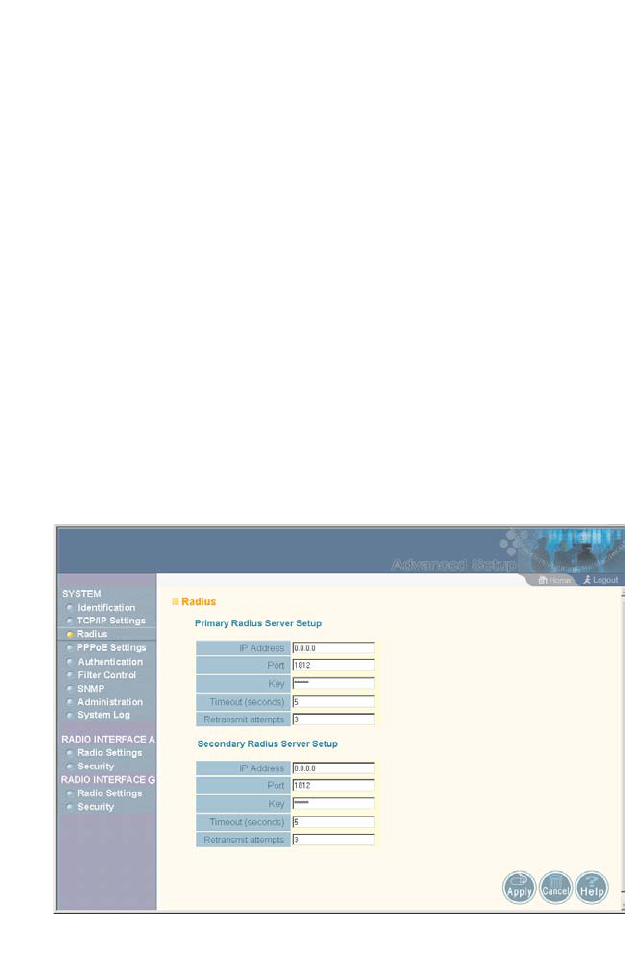
Primary Radius Server Setup – Configure the following settings
to use RADIUS authentication on the access point.
•IP Address: Specifies the IP address or host name of the
RADIUS server.
•Port: The UDP port number used by the RADIUS server for
authentication messages. (Range: 1024-65535;
Default: 1812)
•Key: A shared text string used to encrypt messages between
the access point and the RADIUS server. Be sure that the
same text string is specified on the RADIUS server. Do not
use blank spaces in the string. (Maximum length: 255
characters)
•Timeout: Number of seconds the access point waits for a reply
from the RADIUS server before resending a request.
(Range: 1-60 seconds; Default: 5)
•Retransmit attempts: The number of times the access point
tries to resend a request to the RADIUS server before
authentication fails. (Range: 1-30; Default: 3)
Note: For the Timeout and Retransmit attempts fields, accept the
default values unless you experience problems connecting to the
RADIUS server over the network.
Secondary Radius Server Setup – Configure a secondary
RADIUS server to provide a backup in case the primary server
fails. The access point uses the secondary server if the primary
server fails or becomes inaccessible. Once the access point
switches over to the secondary server, it periodically attempts to
establish communication again with primary server. If
communication with the primary server is re-established, the
secondary server reverts to a backup role.

Advanced Configuration
5-11
CLI Commands for RADIUS – From the global configuration
mode, use the radius-server address command to specify the
address of the primary or secondary RADIUS servers. (The
following example configures the settings for the primary RADIUS
server.) Configure the other parameters for the RADIUS server.
Then use the show show radius command from the Exec mode
to display the current settings for the primary and secondary
RADIUS servers.
AP(config)#radius-server address 192.168.1.25 6-46
AP(config)#radius-server port 181 6-47
AP(config)#radius-server key green 6-47
AP(config)#radius-server timeout 10 6-48
AP(config)#radius-server retransmit 5 6-48
AP(config)#exit
AP#show radius 6-49
Radius Server Information
========================================
IP : 192.168.1.25
Port : 181
Key : *****
Retransmit : 5
Timeout : 10
========================================
Radius Secondary Server Information
========================================
IP : 0.0.0.0
Port : 1812
Key : *****
Retransmit : 3
Timeout : 5
========================================
AP#
System Configuration
5-12
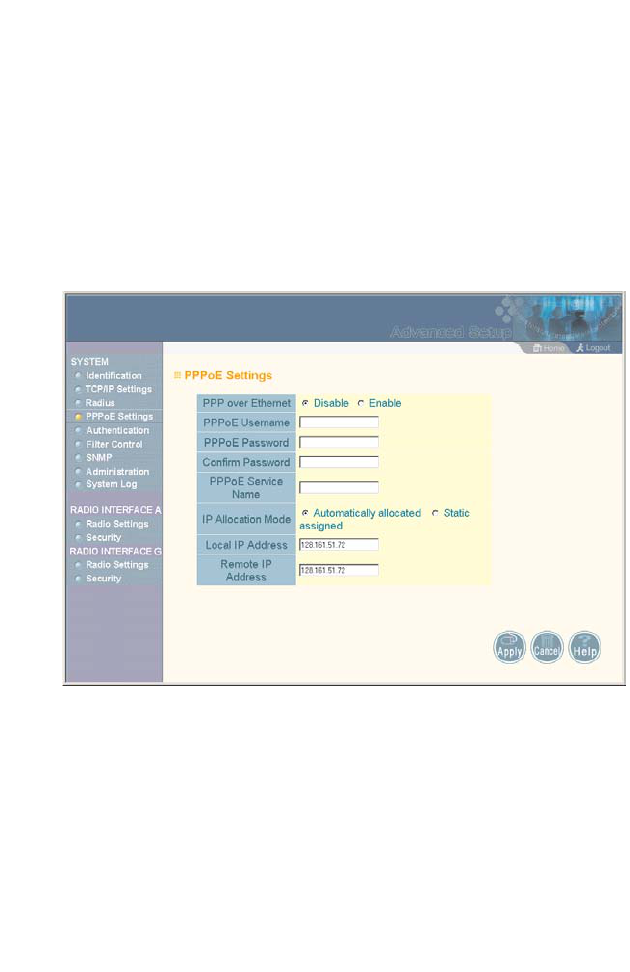
PPPoE Settings
The access point can use a Point-to-Point Protocol over Ethernet
(PPPoE) connection, or tunnel, for management traffic between
the access point and a remote PPPoE server (typically at an ISP).
Examples of management traffic that may be initiated by the
access point and carried over a PPPoE tunnel are RADIUS,
Syslog, or DHCP traffic.
PPP over Ethernet – Enable PPPoE on the RJ-45 Ethernet
interface to pass management traffic between the access point
and a remote PPPoE server. (Default: Disabled)
PPPoE Username – The user name assigned for the PPPoE
tunnel. (Range: 1-63 alphanumeric characters)
PPPoE Password – The password assigned for the PPPoE
tunnel. (Range: 1-63 alphanumeric characters)

Advanced Configuration
5-13
Confirm Password – Use this field to confirm the PPPoE
password.
PPPoE Service Name – The service name assigned for the
PPPoE tunnel. The service name is normally optional, but may be
required by some service providers. (Range: 1-63 alphanumeric
characters)
IP Allocation Mode – This field specifies how IP addresses for the
PPPoE tunnel are configured on the RJ-45 interface. The
allocation mode depends on the type of service provided by the
PPPoE server. If automatic mode is selected, DHCP is used to
allocate the IP addresses for the PPPoE connection. If static
addresses have been assigned by the service provider, you must
manually enter the assigned addresses. (Default: Automatic)
•Automatically allocated: IP addresses are dynamically
assigned by the ISP during PPPoE session initialization.
•Static assigned: Fixed addresses are assigned by the ISP for
both the local and remote IP addresses.
Local IP Address – IP address of the local end of the PPPoE
tunnel. (Must be entered for static IP allocation mode.)
Remote IP Address – IP address of the remote end of the PPPoE
tunnel. (Must be entered for static IP allocation mode.)
System Configuration
5-14
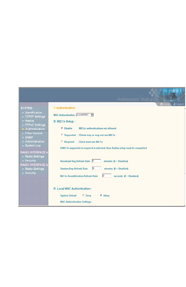
Authentication
Wireless clients can be authenticated for network access by
checking their MAC address against the local database
configured on the access point, or by using a database
configured on a central RADIUS server. Alternatively,
authentication can be implemented using the IEEE 802.1x
network access control protocol.
MAC Authentication – You can configure a list of the MAC
addresses for wireless clients that are authorized to access the
network. This provides a basic level of authentication for wireless
clients attempting to gain access to the network. A database of
authorized MAC addresses can be stored locally on the access
point or remotely on a central RADIUS server.
(Default: Local MAC)

Advanced Configuration
5-15
•Local MAC: The MAC address of the associating station is
compared against the local database stored on the access
point. The Local MAC Authentication section enables the local
database to be set up.
•Radius MAC: The MAC address of the associating station is
sent to a configured RADIUS server for authentication. When
using a RADIUS authentication server for MAC address
authentication, the server must first be configured in the
Radius window (page 5-9).
•Disabled: No checks are performed on an associating
station’s MAC address.
Local MAC Authentication – Configures the local MAC
authentication database. The MAC database provides a
mechanism to take certain actions based on a wireless client’s
MAC address. The MAC list can be configured to allow or deny
network access to specific clients.
•System Default: Specifies a default action for all unknown
MAC addresses (that is, those not listed in the local MAC
database).
- Deny: Blocks access for all MAC addresses except those
listed in the local database as “Allow.”
- Allow: Permits access for all MAC addresses except
those listed in the local database as “Deny.”
•MAC Authentication Settings: Enters specified MAC
addresses and permissions into the local MAC database.
- MAC Address: Physical address of a client. Enter six pairs
of hexadecimal digits separated by hyphens; for example,
00-90-D1-12-AB-89.
- Permission: Select Allow to permit access or Deny to
block access. If Delete is selected, the specified MAC
address entry is removed from the database.

System Configuration
5-16
- Update: Enters the specified MAC address and
permission setting into the local database.
•MAC Authentication Table: Displays current entries in the local
MAC database.
Note: Client station MAC authentication occurs prior to the IEEE 802.1x
authentication procedure configured for the access point.
However, a client’s MAC address provides relatively weak user
authentication, since MAC addresses can be easily captured and
used by another station to break into the network. Using 802.1x
provides more robust user authentication using user names and
passwords or digital certificates. So, although you can configure
the access point to use MAC address and 802.1x authentication
together, it is better to choose one or the other, as appropriate.
Use MAC address authentication for a small network with a
limited number of users. MAC addresses can be manually
configured on the access point itself without the need to set up a
RADIUS server. Use IEEE 802.1x authentication for networks
with a larger number of users and where security is the most
important issue. For 802.1x authentication a RADIUS server is
required in the wired network to control the user credentials of the
wireless clients.
802.1x Setup – IEEE 802.1x is a standard framework for network
access control that uses a central RADIUS server for user
authentication. This control feature prevents unauthorized access
to the network by requiring an 802.1x client application to submit
user credentials for authentication. The 802.1x standard uses the
Extensible Authentication Protocol (EAP) to pass user credentials
(either digital certificates, user names and passwords, or other)
from the client to the RADIUS server. Client authentication is then
verified on the RADIUS server before the access point grants
client access to the network.

Advanced Configuration
5-17
The 802.1x EAP packets are also used to pass dynamic unicast
session keys and static broadcast keys to wireless clients.
Session keys are unique to each client and are used to encrypt
and correlate traffic passing between a specific client and the
access point. You can also enable broadcast key rotation, so the
access point provides a dynamic broadcast key and changes it at
a specified interval.
You can enable 802.1x as optionally supported or as required to
enhance the security of the wireless network.
•Disabled: The access point does not support 802.1x
authentication for any wireless client. After successful
wireless association with the access point, each client is
allowed to access the network.
•Supported: The access point supports 802.1x authentication
only for clients initiating the 802.1x authentication process
(i.e., the access point does not initiate 802.1x authentication).
For clients initiating 802.1x, only those successfully
authenticated are allowed to access the network. For those
clients not initiating 802.1x, access to the network is allowed
after successful wireless association with the access point.
•Required: The access point enforces 802.1x authentication for
all associated wireless clients. If 802.1x authentication is not
initiated by a client, the access point will initiate authentication.
Only those clients successfully authenticated with 802.1x are
allowed to access the network.
When 802.1x is enabled, the broadcast and session key rotation
intervals can also be configured.
•Broadcast Key Refresh Rate: Sets the interval at which the
broadcast keys are refreshed for stations using 802.1x
dynamic keying. (Range: 0-1440 minutes; Default: 0 means
disabled)

System Configuration
5-18
•Session Key Refresh Rate: The interval at which the access
point refreshes unicast session keys for associated clients.
(Range: 0-1440 minutes; Default: 0 means disabled)
•802.1x Re-authentication Refresh Rate: The time period after
which a connected client must be re-authenticated. During the
re-authentication process of verifying the client’s credentials
on the RADIUS server, the client remains connected the
network. Only if re-authentication fails is network access
blocked. (Range: 0-65535 seconds; Default: 0 means
disabled)

Advanced Configuration
5-19
CLI Commands for Local MAC Authentication – Use the
mac-authentication server command from the global
configuration mode to enable local MAC authentication. Set the
default for MAC addresses not in the local table using the
address filter default command, then enter MAC addresses in
the local table using the address filter entry command. To
remove an entry from the table, use the address filter delete
command. To display the current settings, use the show
authentication command from the Exec mode.
AP(config)#mac-authentication server local 6-58
AP(config)#address filter default denied 6-55
AP(config)#address filter entry 00-70-50-cc-99-1a denied 6-56
AP(config)#address filter entry 00-70-50-cc-99-1b allowed
AP(config)#address filter entry 00-70-50-cc-99-1c allowed
AP(config)#address filter delete 00-70-50-cc-99-1c 6-57
AP(config)#exit
AP#show authentication 6-60
Authentication Information
=========================================================
MAC Authentication Server : LOCAL
MAC Auth Session Timeout Value : 300 secs
802.1x : DISABLED
Broadcast Key Refresh Rate : 5 min
Session Key Refresh Rate : 5 min
802.1x Session Timeout Value : 300 secs
Address Filtering : DENIED
System Default : DENY addresses not found in filter table.
Filter Table
MAC Address Status
----------------- ----------
00-70-50-cc-99-1a DENIED
00-70-50-cc-99-1b ALLOWED
=========================================================
AP#

System Configuration
5-20
CLI Commands for RADIUS MAC Authentication – Use the
mac-authentication server command from the global
configuration mode to enable remote MAC authentication. Set the
timeout value for re-authentication using the mac-authentication
session-timeout command. Be sure to also configure
connection settings for the RADIUS server (not shown in the
following example). To display the current settings, use the show
authentication command from the Exec mode.
AP(config)#mac-authentication server remote 6-58
AP(config)#mac-authentication session-timeout 300 6-59
AP(config)#exit
AP#show authentication 6-60
Authentication Information
=========================================================
MAC Authentication Server : REMOTE
MAC Auth Session Timeout Value : 300 secs
802.1x : DISABLED
Broadcast Key Refresh Rate : 5 min
Session Key Refresh Rate : 5 min
802.1x Session Timeout Value : 300 secs
Address Filtering : DENIED
System Default : DENY addresses not found in filter table.
Filter Table
MAC Address Status
----------------- ----------
00-70-50-cc-99-1a DENIED
00-70-50-cc-99-1b ALLOWED
=========================================================
AP#

Advanced Configuration
5-21
CLI Commands for 802.1x Authentication – Use the 802.1x
supported command from the global configuration mode to
enable 802.1x authentication. Set the session and broadcast key
refresh rate, and the re-authentication timeout. To display the
current settings, use the show authentication command from
the Exec mode.
AP(config)#802.1x supported 6-52
AP(config)#802.1x broadcast-key-refresh-rate 5 6-53
AP(config)#802.1x session-key-refresh-rate 5 6-54
AP(config)#802.1x session-timeout 300 6-55
AP(config)#exit
AP#show authentication 6-60
Authentication Information
=========================================================
MAC Authentication Server : REMOTE
MAC Auth Session Timeout Value : 300 secs
802.1x : SUPPORTED
Broadcast Key Refresh Rate : 5 min
Session Key Refresh Rate : 5 min
802.1x Session Timeout Value : 300 secs
Address Filtering : DENIED
System Default : DENY addresses not found in filter table.
Filter Table
MAC Address Status
----------------- ----------
00-70-50-cc-99-1a DENIED
00-70-50-cc-99-1b ALLOWED
=========================================================
AP#
System Configuration
5-22
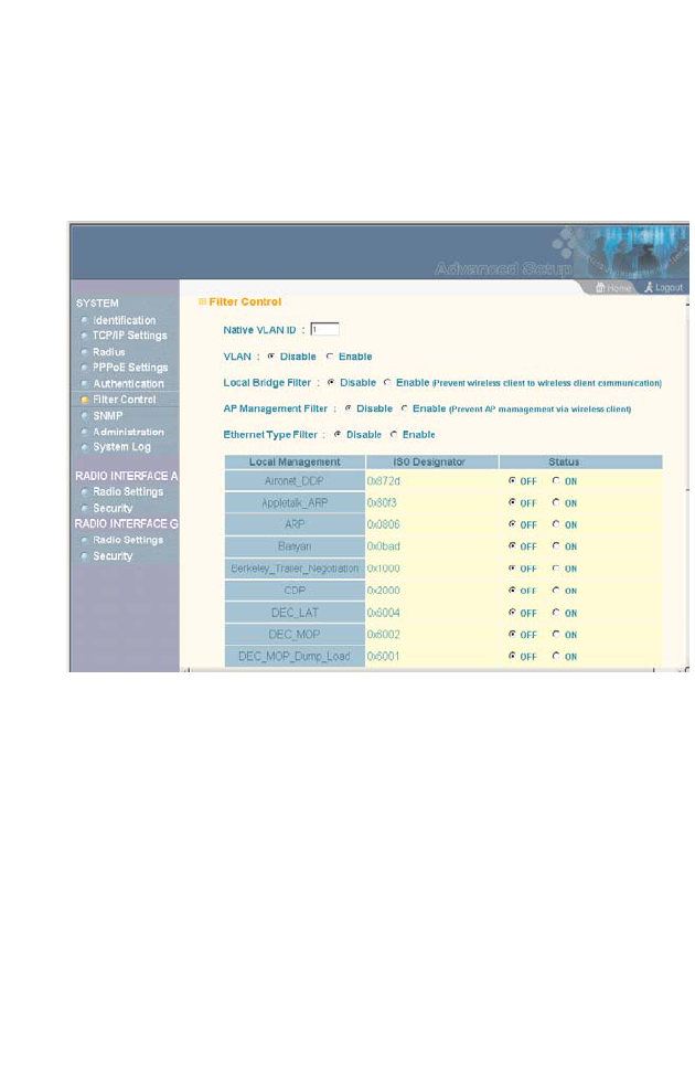
Filter Control
The access point can employ VLAN ID and network traffic frame
filtering to control access to network resources and increase
security.
Native VLAN ID – The VLAN ID assigned to wireless clients that
are not assigned to a specific VLAN by RADIUS server
configuration.
VLAN – Enables or disables VLAN tagging support on the access
point. If enabled, the access point will tag traffic passing from
wireless clients to the wired network with the VLAN ID associated
with each client on the RADIUS server. Up to 64 VLAN IDs can
be mapped to specific wireless clients, allowing users to remain
within the same VLAN as they move around a campus site. This
feature can also be used to control access to network resources
from wireless clients, thereby improving security.

Advanced Configuration
5-23
A VLAN ID (1-4095) is assigned to a client after successful
authentication using IEEE 802.1x and a central RADIUS server.
The user VLAN IDs must be configured on the RADIUS server for
each user authorized to access the network. If a user does not
have a configured VLAN ID, the access point assigns the user to
its own configured native VLAN ID.
When setting up VLAN IDs for each user on the RADIUS server,
be sure to use the RADIUS attributes and values as indicated in
the following table.
Note: The specific configuration of RADIUS server software is beyond
the scope of this guide. Refer to the documentation provided with
the RADIUS server software.
When VLAN filtering is enabled, the access point must also have
802.1x authentication enabled and a RADIUS server configured.
Wireless clients must also support 802.1x client software to be
assigned to a specific VLAN.
When VLAN filtering is disabled, the access point ignores the
VLAN tags on any received frames.
Local Bridge Filter – Controls wireless-to-wireless
communications between clients through the access point.
However, it does not affect communications between wireless
clients and the wired network.
•Disabled: Allows wireless-to-wireless communications
between clients through the access point.
Number RADIUS Attribute Value
64 Tunnel-Type VLAN (13)
65 Tunnel-Medium-Type 802
81 Tunnel-Private-Group VLANID
(1 to 4095 in
hexadecimal)

System Configuration
5-24
•Enable: Blocks wireless-to-wireless communications between
clients through the access point.
AP Management Filter – Controls management access to the
access point from wireless clients. Management interfaces
include the web, Telnet, or SNMP.
•Disabled: Allows management access from wireless clients.
•Enable: Blocks management access from wireless clients.
Ethernet Type Filter – Controls checks on the Ethernet type of all
incoming and outgoing Ethernet packets against the protocol
filtering table.
•Disabled: Access point does not filter Ethernet protocol types.
•Enable: Access point filters Ethernet protocol types based on
the configuration of protocol types in the filter table. If a
protocol has its status set to “ON,” the protocol is filtered from
the access point.
CLI Commands for VLAN Support – From the global
configuration mode use the native-vlanid command to set the
default VLAN ID for the Ethernet interface, then enable VLANs
using the vlan enable command. When you change the access
point’s VLAN support setting, you must reboot the access point to
implement the change.
AP(config)#native-vlanid 3 6-112
AP(config)#vlan enable 6-111
Reboot system now? <y/n>: y
AP#

Advanced Configuration
5-25
To view the current VLAN settings, use the show system
command.
AP#show system
System Information
===========================================================
Serial Number : A252014354
System Up time : 0 days, 1 hours, 28 minutes, 9
seconds
System Name : MEAP
System Location :
System Contact : Contact
System Country Code : 99 - NO_COUNTRY_SET
MAC Address : 00-30-F1-71-D6-40
IP Address : 192.168.1.1
Subnet Mask : 255.255.255.0
Default Gateway : 0.0.0.0
VLAN State : DISABLED
IAPP State : ENABLED
DHCP Client : ENABLED
HTTP Server : ENABLED
HTTP Server Port : 80
Slot Status : Dual band(b/g)
Software Version : v0.0.0.2
===========================================================
AP#

System Configuration
5-26
CLI Commands for Bridge Filtering – Use the filter local-bridge
command from the global configuration mode to prevent
wireless-to-wireless communications through the access point.
Use the filter ap-manage command to restrict management
access from wireless clients. To configure Ethernet protocol
filtering, use the filter ethernet-type enable command to enable
filtering and the filter ethernet-type protocol command to define
the protocols that you want to filter. To remove an entry from the
table, use the address filter delete command. To display the
current settings, use the show filters command from the Exec
mode.
AP(config)#filter local-bridge 6-61
AP(config)#filter ap-manage 6-62
AP(config)#filter ethernet-type enable 6-63
AP(config)#filter ethernet-type protocol ARP 6-64
AP(config)#exit
AP#show filters 6-65
Protocol Filter Information
=========================================================
Local Bridge :ENABLED
AP Management :ENABLED
Ethernet Type Filter :ENABLED
Enabled Protocol Filters
---------------------------------------------------------
Protocol: ARP ISO: 0x0806
=========================================================
AP#
Advanced Configuration
5-27
SNMP
You can use a network management application such as HP’s
OpenView to manage the access point via the Simple Network
Management Protocol (SNMP) from a network management
station. To implement SNMP management, the access point must
have an IP address and subnet mask, configured either manually
or dynamically. Once an IP address has been configured,
appropriate SNMP communities and trap receivers should be
configured.
Community names are used to control management access to
SNMP stations, as well as to authorize SNMP stations to receive
trap messages from the access point. To communicate with the
access point, a management station must first submit a valid
community name for authentication. You therefore need to assign
community names to specified users or user groups and set the
access level.
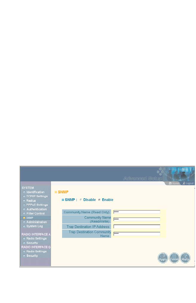
SNMP – Enables or disables SNMP management access and
also enables the access point to send SNMP traps (notifications).
SNMP management is enabled by default.

System Configuration
5-28
Location – A text string that describes the system location.
(Maximum length: 20 characters)
Contact – A text string that describes the system contact.
(Maximum length: 255 characters)
Community Name (Read Only) – Defines the SNMP community
access string that has read-only access. Authorized management
stations are only able to retrieve MIB objects. (Maximum length:
23 characters, case sensitive; Default: public)
Community Name (Read/Write) – Defines the SNMP community
access string that has read/write access. Authorized
management stations are able to both retrieve and modify MIB
objects. (Maximum length: 23 characters, case sensitive; Default:
private)
Trap Destination IP Address – Specifies the recipient of SNMP
notifications. Enter the IP address or the host name. (Host Name:
1 to 20 characters, case sensitive)
Trap Destination Community Name – The community string sent
with the notification operation. (Maximum length: 23 characters,
case sensitive; Default: public)

Advanced Configuration
5-29
CLI Commands for SNMP – Use the snmp-server enable
server command from the global configuration mode. To set
read/write and read-only community names, use the
snmp-server community command. Use the snmp-server
location and snmp-server contact commands to indicate the
physical location of the access point and define a system contact.
The snmp-server host command defines a trap receiver host. To
view the current SNMP settings, use the show snmp command.
AP(config)#snmp-server enable server 6-37
AP(config)#snmp-server community alpha rw 6-35
AP(config)#snmp-server community beta ro
AP(config)#snmp-server location WC-19 6-39
AP(config)#snmp-server contact Paul 6-36
AP(config)#snmp-server host 10.1.19.23 alpha 6-38
AP(config)#exit
AP#show snmp 6-40
SNMP Information
============================================
Service State : Enabled
Community (ro) : ****
Community (rw) : *****
Location : WC-19
Contact : Paul
Traps : Enabled
Host Name/IP : 10.1.19.23
Trap Community : *****
=============================================
AP#
System Configuration
5-30
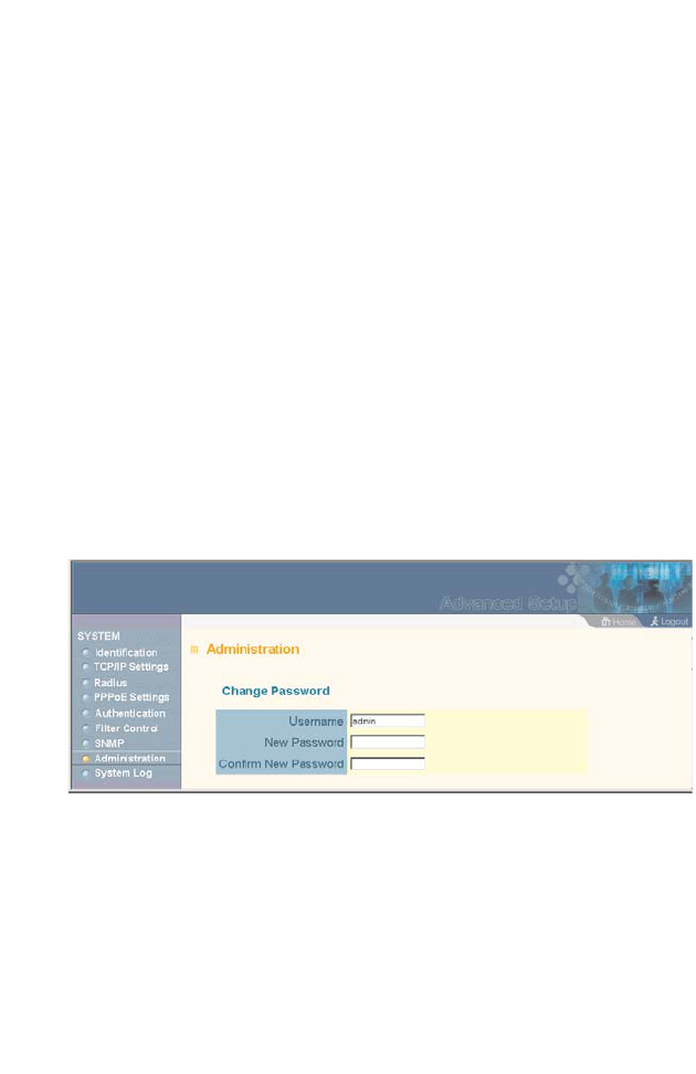
Administration
Changing the Password
Management access to the web and CLI interface on the access
point is controlled through a single user name and password. You
can also gain additional access security by using control filters
(see “Filter Control” on page 5-22).
To protect access to the management interface, you need to
configure an Administrator’s user name and password as soon as
possible. If the user name and password are not configured, then
anyone having access to the access point may be able to
compromise access point and network security.
Note: Pressing the Reset button on the back of the access point for
more than five seconds resets the user name and password to the
factory defaults. For this reason, we recommend that you protect
the access point from physical access by unauthorized persons.
Username – The name of the user. The default name is “admin.”
(Length: 3-16 characters, case sensitive.)
New Password – The password for management access.
(Length: 3-16 characters, case sensitive)
Confirm New Password – Enter the password again for
verification.

Advanced Configuration
5-31
CLI Commands for the User Name and Password – Use the
username and password commands from the CLI configuration
mode.
AP(config)#username bob 6-21
AP(config)#password admin 6-22
AP#
System Configuration
5-32
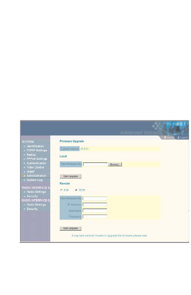
Upgrading Firmware
You can upgrade new access point software from a local file on
the management workstation, or from an FTP or TFTP server.
New software may be provided periodically from your distributor.
After upgrading new software, you must reboot the access point
to implement the new code. Until a reboot occurs, the access
point will continue to run the software it was using before the
upgrade started. Also note that new software that is incompatible
with the current configuration automatically restores the access
point to the factory default settings when first activated after a
reboot.
Before upgrading new software, verify that the access point is
connected to the network and has been configured with a
compatible IP address and subnet mask.

Advanced Configuration
5-33
If you need to download from an FTP or TFTP server, take the
following additional steps:
•Obtain the IP address of the FTP or TFTP server where the
access point software is stored.
•If upgrading from an FTP server, be sure that you have an
account configured on the server with a user name and
password.
•If VLANs are configured on the access point, determine the
VLAN ID with which the FTP or TFTP server is associated,
and then configure the management station, or the network
port to which it is attached, with the same VLAN ID. If you are
managing the access point from a wireless client, the VLAN ID
for the wireless client must be configured on a RADIUS server.
Current version – Version number of runtime code.
Firmware Upgrade Local – Downloads an operation code image
file from the web management station to the access point using
HTTP. Use the Browse button to locate the image file locally on
the management station and click Start Upgrade to proceed.
•New firmware file: Specifies the name of the code file on the
server. The new firmware file name should not contain slashes
(\ or /), the leading letter of the file name should not be a period
(.), and the maximum length for file names is 32 characters for
files on the access point. (Valid characters: A-Z, a-z, 0-9, “.”,
“-”, “_”)

System Configuration
5-34
Firmware Upgrade Remote – Downloads an operation code
image file from a specified remote FTP or TFTP server. After
filling in the following fields, click Start Upgrade to proceed.
•New firmware file: Specifies the name of the code file on the
server.
The new firmware file name should not contain slashes
(\ or /),
the leading letter of the file name should not be a period
(.), and the maximum length for file names on the FTP/TFTP
server is 255 characters or 32 characters for files on the
access point. (Valid characters: A-Z, a-z, 0-9, “.”, “-”, “_”)
•IP Address: IP address or host name of FTP or TFTP server.
•Username: The user ID used for login on an FTP server.
•Password: The password used for login on an FTP server.
Restore Factory Settings – Click the Restore button to reset the
configuration settings for the access point to the factory defaults
and reboot the system. Note that all user configured information
will be lost. You will have to re-enter the default user name
(admin) to re-gain management access to this device.
Reset Access Point – Click the Reset button to reboot the system.
Note: If you have upgraded system software, then you must reboot the
access point to implement the new operation code. New software
that is incompatible with the current configuration automatically
restores the access point to default values when first activated
after a reboot.

Advanced Configuration
5-35
CLI Commands for Downloading Software from a TFTP Server –
Use the copy tftp file command from the Exec mode and then
specify the file type, name, and IP address of the TFTP server.
When the download is complete, the dir command can be used
to check that the new file is present in the access point file
system. To run the new software, use the reset board command
to reboot the access point.
AP#copy config tftp 6-42
TFTP Source file name:syscfg
TFTP Server IP:192.168.1.19
AP#
AP#copy tftp file 6-42
1. Application image
2. Config file
3. Boot block image
Select the type of download<1,2,3>: [1]:2
TFTP Source file name:syscfg
TFTP Server IP:10.1.1.9
AP#dir 6-44
zz-img.bin 1109148
dflt-img.bin 1101452
ap3xartl.sys 637364
syscfg_bak 16972
syscfg 16972
581632 bytes free
AP#reset board 6-14
Reboot system now? <y/n>: y
AP#
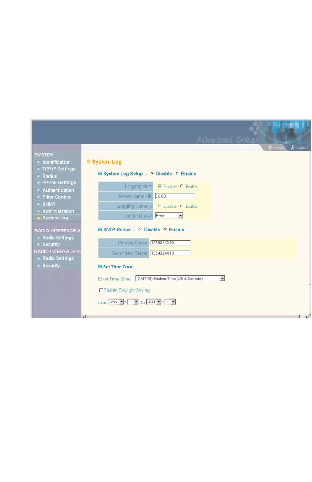
System Configuration
5-36
System Log
The access point can be configured to send event and error
messages to a System Log Server. The system clock can also be
synchronized with a time server, so that all the messages sent to
the Syslog server are stamped with the correct time and date.
Enabling System Logging
The access point supports a logging process that can control
error messages saved to memory or sent to a Syslog server. The
logged messages serve as a valuable tool for isolating access
point and network problems.
System Log Setup – Enables the logging of error messages.
Logging Host – Enables the sending of log messages to a Syslog
server host.
Server Name/IP – The IP address or name of a Syslog server.

Advanced Configuration
5-37
Logging Console – Enables the logging of error messages to the
console.
Logging Level – Sets the minimum severity level for event
logging.
The system allows you to limit the messages that are logged by
specifying a minimum severity level. The following table lists the
error message levels from the most severe (Emergency) to least
severe (Debug). The message levels that are logged include the
specified minimum level up to the Emergency level.
Note: The access point error log can be viewed using the Event Logs
window in the Status section (page 5-71).The Event Logs window
displays the last 128 messages logged in chronological order,
from the newest to the oldest. Log messages saved in the access
point’s memory are erased when the device is rebooted.
Error Level Description
Emergency System unusable
Alert Immediate action needed
Critical Critical conditions (e.g., memory allocation, or free
memory error - resource exhausted)
Error Error conditions (e.g., invalid input, default used)
Warning Warning conditions (e.g., return false, unexpected
return)
Notice Normal but significant condition, such as cold start
Informational Informational messages only
Debug Debugging messages

System Configuration
5-38
CLI Commands for System Logging – To enable logging on the
access point, use the logging on command from the global
configuration mode. The logging level command sets the
minimum level of message to log. Use the logging console
command to enable logging to the console. Use the logging host
command to specify up to four Syslog servers. The CLI also
allows the logging facility-type command to set the facility-type
number to use on the Syslog server. To view the current logging
settings, use the show logging command.
AP(config)#logging on 6-24
AP(config)#logging level alert 6-26
AP(config)#logging console 6-25
AP(config)#logging host 1 10.1.0.3 514 6-24
AP(config)#logging facility-type 19 6-27
AP(config)#exit
AP#show logging 6-28
Logging Information
============================================
Syslog State : Enabled
Logging Host State : Enabled
Logging Console State : Enabled
Server Domain name/IP : 1 10.1.0.3
Logging Level : Error
Logging Facility Type : 16
=============================================
AP#

Advanced Configuration
5-39
Configuring SNTP
Simple Network Time Protocol (SNTP) allows the access point to
set its internal clock based on periodic updates from a time server
(SNTP or NTP). Maintaining an accurate time on the access point
enables the system log to record meaningful dates and times for
event entries. If the clock is not set, the access point will only
record the time from the factory default set at the last bootup.
The access point acts as an SNTP client, periodically sending
time synchronization requests to specific time servers. You can
configure up to two time server IP addresses. The access point
will attempt to poll each server in the configured sequence.
SNTP Server – Configures the access point to operate as an
SNTP client. When enabled, at least one time server IP address
must be specified.
•Primary Server: The IP address of an SNTP or NTP time
server that the access point attempts to poll for a time update.
•Secondary Server: The IP address of a secondary SNTP or
NTP time server. The access point first attempts to update the
time from the primary server; if this fails it attempts an update
from the secondary server.
Note: The access point also allows you to disable SNTP and set the
system clock manually.
Set Time Zone – SNTP uses Coordinated Universal Time (or
UTC, formerly Greenwich Mean Time, or GMT) based on the time
at the Earth’s prime meridian, zero degrees longitude. To display
a time corresponding to your local time, you must indicate the
number of hours your time zone is located before (east) or after
(west) UTC.

System Configuration
5-40
Enable Daylight Saving – The access point provides a way to
automatically adjust the system clock for Daylight Savings Time
changes. To use this feature you must define the month and date
to begin and to end the change from standard time. During this
period the system clock is set back by one hour.
CLI Commands for SNTP – To enable SNTP support on the
access point, from the global configuration mode specify SNTP
server IP addresses using the sntp-server ip command, then
use the sntp-server enable command to enable the service. Use
the sntp-server timezone command to set the time zone for your
location, and the sntp-server daylight-saving command to set
daylight savings. To view the current SNTP settings, use the
show sntp command.
AP(config)#sntp-server ip 10.1.0.19 6-28
AP(config)#sntp-server enable 6-29
AP(config)#sntp-server timezone +8 6-32
AP(config)#sntp-server daylight-saving 6-31
Enter Daylight saving from which month<1-12>: 3
and which day<1-31>: 31
Enter Daylight saving end to which month<1-12>: 10
and which day<1-31>: 31
AP(config)#exit
AP#show sntp 6-32
SNTP Information
=========================================================
Service State : Enabled
SNTP (server 1) IP : 137.92.140.80
SNTP (server 2) IP : 192.43.244.18
Current Time : 19 : 35, Oct 10th, 2003
Time Zone : +8 (TAIPEI, BEIJING)
Daylight Saving : Enabled, from Mar, 31th to Oct,
31th
=========================================================
AP#

Advanced Configuration
5-41
CLI Commands for the System Clock – The following example
shows how to manually set the system time when SNTP server
support is disabled on the access point.
AP(config)#no sntp-server enable 6-29
AP(config)#sntp-server date-time 6-30
Enter Year<1970-2100>: 2003
Enter Month<1-12>: 10
Enter Day<1-31>: 10
Enter Hour<0-23>: 18
Enter Min<0-59>: 35
AP(config)#

System Configuration
5-42
Radio Interface
The IEEE 802.11a and 802.11g interfaces include configuration
options for radio signal characteristics and wireless security
features. The configuration options are nearly identical, and are
therefore both covered in this section of the manual.
The access point can operate in four modes, IEEE 802.11a only,
802.11b & g, 802.11g only and 802.11b only. Also note that
802.11g is backward compatible with 802.11b. These interfaces
are configured independently under the following web pages:
•Radio Interface 1: 802.11a
•Radio Interface 2: 802.11b/g
Note: The radio channel settings for the access point are limited by local
regulations, which determine the number of channels that are
available.
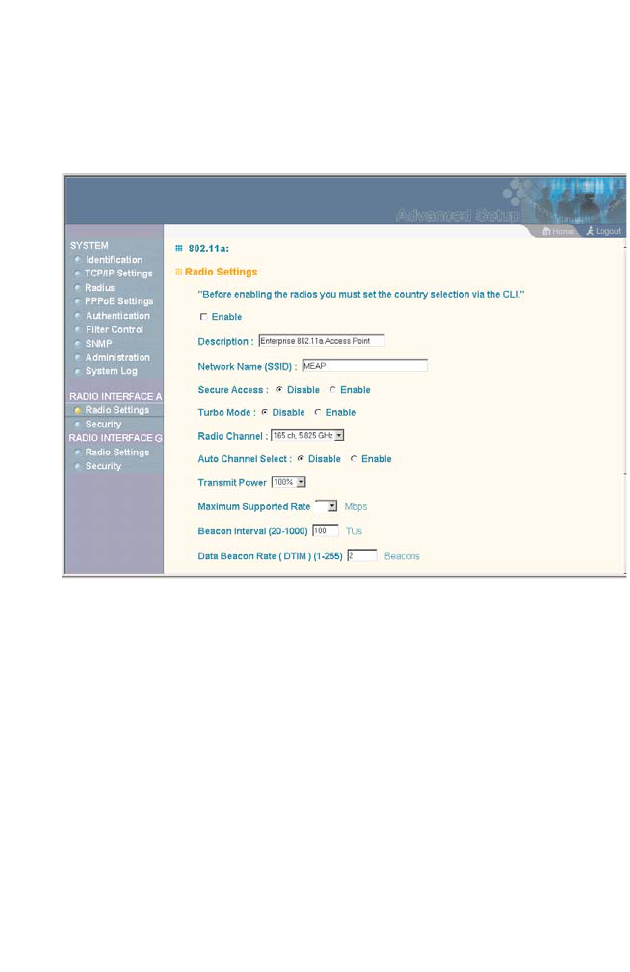
Radio Interface
5-43
Radio Settings (802.11a)
The IEEE 802.11a interface operates within the 5 GHz band, at
up to 54 Mbps in normal mode or up to 108 Mbps in Turbo mode.
Enable – Enables radio communications on the access point.
(Default: Enabled)
Turbo Mode – The normal 802.11a wireless operation mode
provides connections up to 54 Mbps. Turbo Mode is an enhanced
mode (not regulated in IEEE 802.11a) that provides a higher data
rate of up to 108 Mbps. Enabling Turbo Mode allows the access
point to provide connections up to 108 Mbps. (Default: Disabled)
Note: In normal mode, the access point provides a channel bandwidth
of 20 MHz, and supports the maximum number of channels
permitted by local regulations (e.g., 11 channels for the United
States). In Turbo Mode, the channel bandwidth is increased to
40 MHz to support the increased data rate. However, this reduces
the number of channels supported (e.g., 5 channels for the United
States).
108

System Configuration
5-44
Radio Channel – The radio channel that the
access point uses to communicate with
wireless clients. When multiple access points
are deployed in the same area, set the channel
on neighboring access points at least four
channels apart to avoid interference with each
other. For example, in the United States you
can deploy up to four access points in the
same area .
Also note that the channel for wireless clients
is automatically set to the same as that used by
the access point to which it is linked.
Auto Channel Select – Enables the access
point to automatically select an unoccupied
radio channel. (Default: Enabled)
Transmit Power – Adjusts the power of the radio signals
transmitted from the access point. The higher the transmission
power, the farther the transmission range. Power selection is not
just a trade off between coverage area and maximum supported
clients. You also have to ensure that high-power signals do not
interfere with the operation of other radio devices in the service
area. (Options: 100%, 50%, 25%, 12%, minimum; Default: 100%)
Maximum Supported Rate – The maximum data rate at which a
client can connect to the access point. The maximum
transmission distance is affected by the data rate. The lower the
data rate, the longer the transmission distance.
Normal Mode
Turbo Mode

Radio Interface
5-45
Beacon Interval – The rate at which beacon signals are
transmitted from the access point. The beacon signals allow
wireless clients to maintain contact with the access point. They
may also carry power-management information.
(Range: 20-1000 TUs; Default: 100 TUs)
Data Beacon Rate – The rate at which stations in sleep mode
must wake up to receive broadcast/multicast transmissions.
Known also as the Delivery Traffic Indication Map (DTIM) interval,
it indicates how often the MAC layer forwards broadcast/multicast
traffic, which is necessary to wake up stations that are using
Power Save mode. The default value of 2 indicates that the
access point will save all broadcast/multicast frames for the Basic
Service Set (BSS) and forward them after every second beacon.
Using smaller DTIM intervals delivers broadcast/multicast frames
in a more timely manner, causing stations in Power Save mode to
wake up more often and drain power faster. Using higher DTIM
values reduces the power used by stations in Power Save mode,
but delays the transmission of broadcast/multicast frames.
(Range: 1-255 beacons; Default: 2 beacons)
RTS Threshold – Sets the packet size threshold at which a
Request to Send (RTS) signal must be sent to a receiving station
prior to the sending station starting communications. The access
point sends RTS frames to a receiving station to negotiate the
sending of a data frame. After receiving an RTS frame, the station
sends a CTS (clear to send) frame to notify the sending station
that it can start sending data.
If the RTS threshold is set to 0, the access point never sends RTS
signals. If set to 2347, the access point always sends RTS
signals. If set to any other value, and the packet size equals or
exceeds the RTS threshold, the RTS/CTS (Request to Send /
Clear to Send) mechanism will be enabled.

System Configuration
5-46
The access points contending for the medium may not be aware
of each other. The RTS/CTS mechanism can solve this “Hidden
Node Problem.” (Range: 0-2347 bytes: Default: 2347 bytes)
CLI Commands for the 802.11a Wireless Interface – From the
global configuration mode, enter the interface wireless a
command to access the 802.11a radio interface. Set the interface
SSID using the ssid command and, if required, configure a name
for the interface using the description command. You can also
use the closed-system command to stop sending the SSID in
beacon messages. Use the turbo command to enable this
feature before setting the radio channel with the channel
command. Set any other parameters as required. To view the
current 802.11a radio settings, use the show interface wireless
a command.
AP(config)#interface wireless a 6-70
Enter Wireless configuration commands, one per line.
AP(if-wireless a)#description RD-AP 6-85
AP(if-wireless a)#ssid r&d 6-90
AP(if-wireless a)#turbo 6-89
AP(if-wireless a)#channel 42 6-88
AP(if-wireless a)#closed-system 6-86
AP(if-wireless a)#transmit-power full 6-99
AP(if-wireless a)#speed 9 6-87
AP(if-wireless a)#max-association 32 6-100
AP(if-wireless a)#beacon-interval 150 6-90
AP(if-wireless a)#dtim-period 5 6-91
AP(if-wireless a)#fragmentation-length 512 6-92
AP(if-wireless a)#rts-threshold 256 6-93
AP(if-wireless a)#end

Radio Interface
5-47
AP#show interface wireless a 6-107
Wireless Interface 802.11a Information
==========================================================
----------------Identification----------------------------
Description : Enterprise 802.11a Access Point
SSID : r&d
Turbo Mode : ON
Channel : 42 (AUTO)
Status : Enabled
----------------802.11 Parameters-------------------------
Transmit Power : FULL (17 dBm)
Max Station Data Rate : 9Mbps
Fragmentation Threshold : 512 bytes
RTS Threshold : 256 bytes
Beacon Interval : 150 TUs
DTIM Interval : 5 beacons
Maximum Association : 32 stations
----------------Security----------------------------------
Closed System : DISABLED
Multicast cipher : WEP
Unicast cipher : TKIP
WPA clients : SUPPORTED
WPA Key Mgmt Mode : DYNAMIC
WPA PSK Key Type : HEX
Encryption : DISABLED
Default Transmit Key : 1
Static Keys :
Key 1: EMPTY Key 2: EMPTY Key 3: EMPTY Key 4: EMPTY
Authentication Type : OPEN
==========================================================
AP#
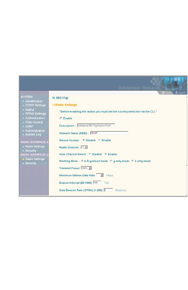
System Configuration
5-48
Radio Settings (802.11g)
The IEEE 802.11g standard operates within the 2.4 GHz band at
up to 108 Mbps (include turbo mode) . Also note that because the IEEE 802.11g
standard is an extension of the IEEE 802.11b standard, it allows
clients with 802.11b wireless network cards to associate to an
802.11g access point.
Enable – Enables radio communications on the access point.
(Default: Enabled)
Radio Channel – The radio channel that the access point uses to
communicate with wireless clients. When multiple access points
are deployed in the same area, set the channel on neighboring
access points at least five channels apart to avoid interference
with each other. For example, in the United States you can deploy
up to three access points in the same area (e.g., channels 1, 6,
11). Also note that the channel for wireless clients is automatically
108
The operating frequency channel will be restricted to the
country user located by software before importing.

Radio Interface
5-49
set to the same as that used by the access point to which it is
linked. (Range: 1-11; Default: 1)
Auto Channel Select – Enables the access point to automatically
select an unoccupied radio channel. (Default: Enabled)
Maximum Supported Rate – The maximum data rate at
which a client can connect to the access point. The
maximum transmission distance is affected by the data
rate. The lower the data rate, the longer the transmission
distance. (Default: 108 Mbps)
For a description of the remaining configuration items, see
“Radio Settings (802.11a)” on page 5-43.
The operating frequency channel will be restricted to the country user
located by software before importing.
Note:

System Configuration
5-50
CLI Commands for the 802.11g Wireless Interface – From the
global configuration mode, enter the interface wireless g
command to access the 802.11g radio interface. Set the interface
SSID using the ssid command and, if required, configure a name
for the interface using the description command. You can also
use the closed-system command to stop sending the SSID in
beacon messages. Select a radio channel or set selection to Auto
using the channel command. Set any other parameters as
required. To view the current 802.11g radio settings, use the
show interface wireless g command.
AP(config)#interface wireless g 6-70
Enter Wireless configuration commands, one per line.
AP(if-wireless g)#description RD-AP 6-85
AP(if-wireless g)#ssid r&d 6-90
AP(if-wireless g)#channel auto 6-88
AP(if-wireless a)#closed-system 6-86
AP(if-wireless a)#transmit-power full 6-99
AP(if-wireless g)#speed 6 6-87
AP(if-wireless g)#max-association 32 6-100
AP(if-wireless g)#beacon-interval 150 6-90
AP(if-wireless g)#dtim-period 5 6-91
AP(if-wireless g)#fragmentation-length 512 6-92
AP(if-wireless g)#rts-threshold 256 6-93
AP(if-wireless g)#exit

Radio Interface
5-51
AP#show interface wireless g 6-107
Wireless Interface Information
===========================================================
----------------Identification-----------------------------
Description : Enterprise 802.11g Access Point
SSID : r&d
Channel : 11 (AUTO)
Status : Enabled
----------------802.11 Parameters--------------------------
Transmit Power : FULL (14 dBm)
Max Station Data Rate : 6Mbps
Fragmentation Threshold : 512 bytes
RTS Threshold : 256 bytes
Beacon Interval : 150 TUs
DTIM Interval : 5 beacons
Maximum Association : 32 stations
----------------Security-----------------------------------
Closed System : DISABLED
Multicast cipher : WEP
Unicast cipher : TKIP
WPA clients : SUPPORTED
WPA Key Mgmt Mode : DYNAMIC
WPA PSK Key Type : HEX
Encryption : DISABLED
Default Transmit Key : 1
Static Keys :
Key 1: EMPTY Key 2: EMPTY Key 3: EMPTY Key 4: EMPTY
Authentication Type : OPEN
===========================================================
AP#

System Configuration
5-52
Security
The access point is configured by default as an “open system,”
which broadcasts a beacon signal including the configured SSID.
Wireless clients can read the SSID from the beacon, and
automatically reset their SSID to allow immediate connection to
the nearest access point.
To improve wireless network security, you have to implement two
main functions:
•Authentication: It must be verified that clients attempting to
connect to the network are authorized users.
•Traffic Encryption: Data passing between the access point and
clients must be protected from interception and evesdropping.
For a more secure network, the access point can implement one
or a combination of the following security mechanisms:
•Wired Equivalent Privacy (WEP) page 5-53
•IEEE 802.1x page 5-16
•Wireless MAC address filtering page 5-14
•Wi-Fi Protected Access (WPA) page 5-59

Radio Interface
5-53
The security mechanisms that may be employed depend on the
level of security required, the network and management
resources available, and the software support provided on
wireless clients. A summary of wireless security considerations is
listed in the following table.
Note: Although a WEP static key is not needed for WEP over 802.1x,
WPA over 802.1x, and WPA PSK modes, you must enable WEP
encryption through the web or CLI in order to enable all types of
encryption in the access point.
Security
Mechanism Client
Support Implementation Considerations
WEP Built-in support on all
802.11a and 802.11g
devices
• Provides only weak security
• Requires manual key management
WEP over
802.1x Requires 802.1x client
support in system or by
add-in software
(support provided in
Windows 2000 SP3 or
later and Windows XP)
• Provides dynamic key rotation for
improved WEP security
• Requires configured RADIUS server
• 802.1x EAP type may require
management of digital certificates for
clients and server
MAC Address
Filtering Uses the MAC address
of client network card • Provides only weak user
authentication
• Management of authorized MAC
addresses
• Can be combined with other methods
for improved security
• Optionally configured RADIUS server
WPA over
802.1x Mode Requires WPA-enabled
system and network
card driver
(native support provided
in Windows XP)
• Provides robust security in WPA-only
mode (i.e., WPA clients only)
• Offers support for legacy WEP clients,
but with increased security risk (i.e.,
WEP authentication keys disabled)
• Requires configured RADIUS server
• 802.1x EAP type may require
management of digital certificates for
clients and server
WPA PSK
Mode Requires WPA-enabled
system and network
card driver
(native support provided
in Windows XP)
• Provides good security in small
networks
• Requires manual management of
pre-shared key
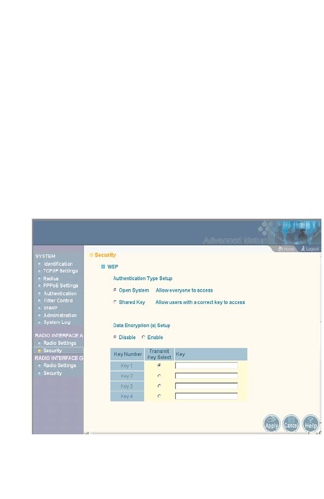
System Configuration
5-54
Wired Equivalent Privacy (WEP)
WEP provides a basic level of security, preventing unauthorized
access to the network and encrypting data transmitted between
wireless clients and the access point. WEP uses static shared
keys (fixed-length hexadecimal or alphanumeric strings) that are
manually distributed to all clients that want to use the network.
WEP is the security protocol initially specified in the IEEE 802.11
standard for wireless communications. Unfortunately, WEP has
been found to be seriously flawed and cannot be recommended
for a high level of network security. For more robust wireless
security, the access point provides Wi-Fi Protected Access (WPA)
for improved data encryption and user authentication.
Setting up shared keys enables the basic IEEE 802.11 Wired
Equivalent Privacy (WEP) on the access point to prevent
unauthorized access to the network.

Radio Interface
5-55
If you choose to use WEP shared keys instead of an open
system, be sure to define at least one static WEP key for user
authentication and data encryption. Also, be sure that the WEP
shared keys are the same for each client in the wireless network.
Authentication Type Setup – Sets the access point to
communicate as an open system that accepts network access
attempts from any client, or with clients using pre-configured
static shared keys.
•Open System: Select this option if you plan to use WPA or
802.1x as a security mechanism. If you don’t set up any other
security mechanism on the access point, the network has no
protection and is open to all users. This is the default setting.
•Shared Key: Sets the access point to use WEP shared keys.
If this option is selected, you must configure at least one key
on the access point and all clients.
Note: To use 802.1x on wireless clients requires a network card driver
and 802.1x client software that supports the EAP authentication
type that you want to use. Windows 2000 SP3 or later and
Windows XP provide 802.1x client support. Windows XP also
provides native WPA support. Other systems require additional
client software to support 802.1x and WPA.
Wired Equivalent Privacy (WEP) Setup – Enable or disable the
access point to use WEP shared keys for data encryption. If this
option is selected, you must configure at
least one key on the
access point and all clients. (Default: Disabled)
Note: Although WEP keys are not needed for WPA, you must enable
WEP encryption through the web or CLI in order to enable all
types of encryption in the access point.

System Configuration
5-56
Shared Key Setup – Select 64 Bit, 128 Bit, or 152 Bit key length.
Note that the same size of encryption key must be supported on
all wireless clients. 152 Bit key length is only supported on
802.11a radio. (Default: 128 Bit)
Key Type – Select the preferred method of entering WEP
encryption keys on the access point and enter up to four keys:
•Hexadecimal: Enter keys as 10 hexadecimal digits (0 to 9 and
A to F) for 64 bit keys, 26 hexadecimal digits for 128 bit keys,
or 32 hexadecimal digits for 152 bit keys (802.11a radio only).
•Alphanumeric: Enter keys as 5 alphanumeric characters for 64
bit keys, 13 alphanumeric characters for 128 bit keys, or 16
alphanumeric characters for 152 bit keys (802.11a radio only).
•Transmit Key Select: Selects the key number to use for
encryption. If the clients have all four keys configured to the
same values, you can change the encryption key to any of the
four settings without having to update the client keys.
Note: Key index and type must match that configured on the clients.
The configuration settings for WEP are summarized below:
WEP only WEP over 802.1x
Authentication Type: Shared Key
WEP (encryption): Enabled
WPA clients only: Disabled
Multicast Cipher: WEP
Shared Key: 64/128/152
Key Type -
Hex: 10/26/32 characters
ASCII: 5/13/16 characters
Transmit Key: 1/2/3/4 (set index)
802.1x = Disabled1
MAC Authentication: Any setting2
Authentication Type: Open System
WEP (encryption): Enabled
WPA clients only: Disabled
Multicast Cipher: WEP
Shared Key: 64/128
802.1x = Required1
MAC Authentication: Disabled/Local2
1: See Authentication (page 5-14)
2: See Radius (page 5-9)

Radio Interface
5-57
CLI Commands for WEP Shared Key Security – From the 802.11a
or 802.11g interface configuration mode, use the
authentication
command to enable WEP shared-key authentication and the
encryption
command to enable WEP encryption. Use the
multicast-cipher
command to select WEP cipher type. To enter
WEP keys, use the
key
command, and then set one key as the
transmit key using the
transmit-key
command. Then disable
802.1x port authentication with the
802.1x
command. To view the
current security settings, use the
show interface wireless a
or
show interface wireless g
command.
AP(config)#interface wireless g 6-70
Enter Wireless configuration commands, one per line.
AP(if-wireless g)#authentication shared 6-94
AP(if-wireless g)#encryption 128 6-95
AP(if-wireless g)#multicast-cipher wep 6-101
AP(if-wireless g)#key 1 128 ascii abcdeabcdeabc 6-97
AP(if-wireless g)#transmit-key 1 6-98
AP(if-wireless g)#end
AP(config)#no 802.1x 6-52
AP(config)#end
AP#show interface wireless g 6-107
Wireless Interface 802.11g Information
==========================================================
----------------Identification----------------------------
Description : Enterprise 802.11g Access Point
SSID : r&d
Channel : 11 (AUTO)
Status : Enabled
----------------802.11 Parameters-------------------------
Transmit Power : FULL (13 dBm)
Max Station Data Rate : 54Mbps
Fragmentation Threshold : 2346 bytes
RTS Threshold : 2347 bytes
Beacon Interval : 100 TUs
DTIM Interval : 2 beacons
Maximum Association : 64 stations

System Configuration
5-58
Note: The index and length values used in the key command must be
the same values used in the encryption and transmit-key
commands.
CLI Commands for WEP over 802.1x Security – From the
802.11a or 802.11g interface configuration mode, use the
authentication command to select open system authentication.
Use the multicast-cipher command to select WEP cipher type.
Then set 802.1x to required with 802.1x command, and disable
MAC authentication with the mac-authentication command. To
view the current 802.11g security settings, use the show
interface wireless g command (not shown in example).
----------------Security----------------------------------
Closed System : DISABLED
Multicast cipher : WEP
Unicast cipher : TKIP
WPA clients : SUPPORTED
WPA Key Mgmt Mode : PRE SHARED KEY
WPA PSK Key Type : HEX
Encryption : 128-BIT ENCRYPTION
Default Transmit Key : 1
Static Keys :
Key 1: ***** Key 2: EMPTY Key 3: EMPTY Key 4: EMPTY
Authentication Type : SHARED
==========================================================
AP#
AP(config)#interface wireless g 6-70
Enter Wireless configuration commands, one per line.
AP(if-wireless g)#authentication open 6-94
AP(if-wireless g)#encryption 128 6-95
AP(if-wireless g)#multicast-cipher wep 6-101
AP(if-wireless g)#end
AP(config)#802.1x required 6-52
AP(config)#no mac-authentication 6-58
AP(config)#
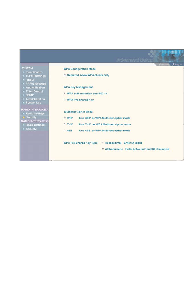
Radio Interface
5-59
Wi-Fi Protected Access (WPA)
WPA employs a combination of several technologies to provide
an enhanced security solution for 802.11 wireless networks.
The access point supports the following WPA components and
features:
IEEE 802.1x and the Extensible Authentication Protocol
(EAP):
WPA employs 802.1x as its basic framework for user
authentication and dynamic key management. The 802.1x client
and RADIUS server should use an appropriate EAP type—such
as EAP-TLS (Transport Layer Security), EAP-TTLS (Tunneled
TLS), or PEAP (Protected EAP)—for strongest authentication.
Working together, these protocols provide “mutual authentication”
between a client, the access point, and a RADIUS server that
prevents users from accidentally joining a rogue network. Only
when a RADIUS server has authenticated a user’s credentials will
encryption keys be sent to the access point and client.

System Configuration
5-60
Note: To implement WPA on wireless clients requires a WPA-enabled
network card driver and 802.1x client software that supports the
EAP authentication type that you want to use. Windows XP
provides native WPA support, other systems require additional
software.
Temporal Key Integrity Protocol (TKIP): WPA specifies TKIP as
the data encryption method to replace WEP. TKIP avoids the
problems of WEP static keys by dynamically changing data
encryption keys. Basically, TKIP starts with a master (temporal)
key for each user session and then mathematically generates
other keys to encrypt each data packet. TKIP provides further
data encryption enhancements by including a message integrity
check for each packet and a re-keying mechanism, which
periodically changes the master key.
WPA Pre-Shared Key (PSK) Mode: For enterprise deployment,
WPA requires a RADIUS authentication server to be configured
on the wired network. However, for small office networks that may
not have the resources to configure and maintain a RADIUS
server, WPA provides a simple operating mode that uses just a
pre-shared password for network access. The Pre-Shared Key
mode uses a common password for user authentication that is
manually entered on the access point and all wireless clients. The
PSK mode uses the same TKIP packet encryption and key
management as WPA in the enterprise, providing a robust and
manageable alternative for small networks.
Mixed WPA and WEP Client Support: WPA enables the access
point to indicate its supported encryption and authentication
mechanisms to clients using its beacon signal. WPA-compatible
clients can likewise respond to indicate their WPA support. This
enables the access point to determine which clients are using
WPA security and which are using legacy WEP. The access point
uses TKIP unicast data encryption keys for WPA clients and WEP
unicast keys for WEP clients. The global encryption key for

Radio Interface
5-61
multicast and broadcast traffic must be the same for all clients,
therefore it restricts encryption to a WEP key.
When access is opened to both WPA and WEP clients, no
authentication is provided for the WEP clients through shared
keys. To support authentication for WEP clients in this mixed
mode configuration, you can use either MAC authentication or
802.1x authentication.
Advanced Encryption Standard (AES) Support: WPA specifies
AES encryption as an optional alternative to TKIP and WEP. AES
provides very strong encryption using a completely different
ciphering algorithm to TKIP and WEP. The developing IEEE
802.11i wireless security standard has specified AES as an
eventual replacement for TKIP and WEP. However, because of
the difference in ciphering algorithms, AES requires new
hardware support in client network cards that is currently not
widely available. The access point includes AES support as a
future security enhancement.
The WPA configuration parameters are described below:
Authentication Type Setup – When using WPA, set the access
point to communicate as an open system to disable WEP keys.
Note: Although WEP keys are not needed for WPA, you must enable
WEP encryption through the web or CLI in order to enable all
types of encryption in the access point. For example, set Wired
Equivalent Privacy (WEP) Setup to “Enable” on the Security page.
WPA Configuration Mode – The access point can be configured
to allow only WPA-enabled clients to access the network, or also
allow clients only capable of supporting WEP.

System Configuration
5-62
WPA Key Management – WPA can be configured to work in an
enterprise environment using IEEE 802.1x and a RADIUS server
for user authentication. For smaller networks, WPA can be
enabled using a common pre-shared key for client authentication
with the access point.
•WPA authentication over 802.1x: The WPA enterprise mode
that uses IEEE 802.1x to authenticate users and to
dynamically distribute encryption keys to clients.
•WPA Pre-shared Key: The WPA mode for small networks that
uses a common password string that is manually distributed.
If this mode is selected, be sure to also specify the key string.
Multicast Cipher Mode – Selects an encryption method for the
global key used for multicast and broadcast traffic, which is
supported by all wireless clients.
•WEP: WEP is the first generation security protocol used to
encrypt data crossing the wireless medium using a fairly short
key. Communicating devices must use the same WEP key to
encrypt and decrypt radio signals. WEP has many security
flaws, and is not recommended for transmitting
highly-sensitive data.
•TKIP: TKIP provides data encryption enhancements including
per-packet key hashing (that is, changing the encryption key
on each packet), a message integrity check, an extended
initialization vector with sequencing rules, and a re-keying
mechanism.
•AES: AES has been designated by the National Institute of
Standards and Technology as the successor to the Data
Encryption Standard (DES) encryption algorithm, and will be
used by the U.S. government for encrypting all sensitive,
nonclassified information. Because of its strength, and
resistance to attack, AES is also being incorporated as part of
the 802.11 standard.

Radio Interface
5-63
WPA Pre-Shared Key Type – If the WPA pre-shared-key mode is
used, all wireless clients must be configured with the same key to
communicate with the access point.
•Hexadecimal: Enter a key as a string of 64 hexadecimal
numbers.
•Alphanumeric: Enter a key as an easy-to-remember form of
letters and numbers. The string must be from 8 to 63
characters, which can include spaces.
The configuration settings for WPA are summarized below:
WPA pre-shared key only WPA over 802.1x
Authentication Type: Open System
WEP (encryption): Enabled1
WPA clients only: Enabled
WPA Mode: Pre-shared-key
Multicast Cipher: WEP/TKIP/AES2
WPA PSK Type -
Hex: 64 characters
ASCII: 8-63 characters
Shared Key: 64/128/152
802.1x = Disabled3
MAC Authentication: Disabled/Local4
Authentication Type: Open System
WEP (encryption): Enabled1
WPA clients only: Enabled
WPA Mode: WPA over 802.1x
Multicast Cipher: WEP/TKIP/AES2
Shared Key: 64/128/152
802.1x = Required3
MAC Authentication: Disabled/Local4
1: Although WEP keys are not needed for WPA, you must enable WEP encryption
through the web or CLI in order to enable all types of encryption in the access point.
For example, use the CLI encryption command to set Encryption = 64, 128 or 152,
thus enabling encryption (i.e., all types of encryption) in the access point.
2: Do not use WEP unless the access point must support both WPA and WEP clients.
3: See Authentication (page 5-14)
4: See Radius (page 5-9)

System Configuration
5-64
CLI Commands for WPA Pre-shared Key Security – From the
802.11a or 802.11g interface configuration mode, use the
authentication command to set the access point to “Open
System.” Use the WEP encryption command to enable all types
of encryption. To enable WPA to be required for all clients, use the
wpa-clients command. Use the wpa-mode command to enable
the Pre-shared Key mode. To enter a key value, use the
wpa-psk-type command to specify a hexadecimal or
alphanumeric key, and then use the wpa-preshared-key
command to define the key. Then disable 802.1x and MAC
authentication. To view the current 802.11g security settings, use
the show interface wireless a or show interface wireless g
command (not shown in example).
AP(config)#interface wireless g 6-70
Enter Wireless configuration commands, one per line.
AP(if-wireless g)#authentication open 6-94
AP(if-wireless g)#encryption 128 6-95
AP(if-wireless g)#wpa-clients required 6-102
AP(if-wireless g)#wpa-mode pre-shared-key 6-104
AP(if-wireless g)#wpa-psk-type alphanumeric 6-106
AP(if-wireless g)#wpa-preshared-key ASCII asecret 6-105
AP(if-wireless g)#end
AP(config)#no 802.1x 6-52
AP(config)#no mac-authentication 6-58

Radio Interface
5-65
CLI Commands for WPA over 802.1x Security – From the
802.11a or 802.11g interface configuration mode, use the
authentication command to set the access point to “Open
System.” Use the WEP encryption command to enable all types
of encryption. Use the wpa-clients command to set WPA to be
required or supported for clients. Use the wpa-mode command
to enable WPA dynamic keys over 802.1x. Set the broadcast and
multicast key encryption using the multicast-cipher command.
Then set 802.1x to required, and disable MAC authentication. To
view the current 802.11g security settings, use the show
interface wireless g command (not shown in example).
AP(config)#interface wireless g 6-70
Enter Wireless configuration commands, one per line.
AP(if-wireless g)#authentication open 6-94
AP(if-wireless g)#encryption 128 6-95
AP(if-wireless g)#wpa-clients required 6-102
AP(if-wireless g)#wpa-mode dynamic 6-104
AP(if-wireless g)#multicast-cipher TKIP 6-101
AP(if-wireless g)#end
AP(config)#802.required 6-52
AP(config)#no mac-authentication 6-58
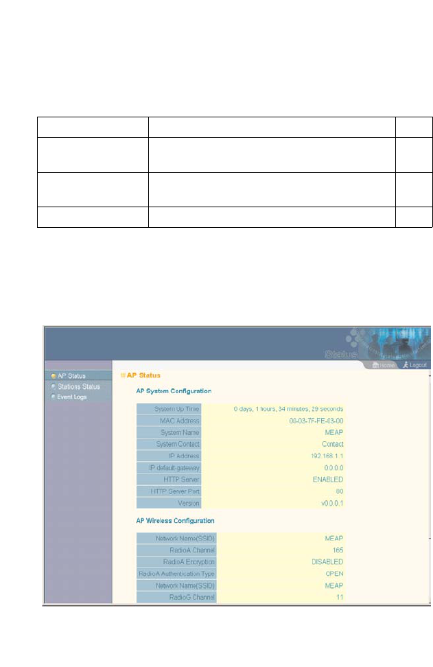
System Configuration
5-66
Status Information
The Status page includes information on the following items:
Access Point Status
The AP Status window displays basic system configuration
settings, as well as the settings for the wireless interface.
Menu Description Page
AP Status Displays configuration settings for the basic
system and the wireless interface 5-66
Station Status Shows the wireless clients currently
associated with the access point 5-69
Event Logs Shows log messages stored in memory 5-71

Status Information
5-67
AP System Configuration – The AP System Configuration table
displays the basic system configuration settings:
•System Up Time: Length of time the management agent has
been up.
•MAC Address: The physical layer address for this device.
•System Name: Name assigned to this system.
•System Contact: Administrator responsible for the system.
•IP Address: IP address of the management interface for this
device.
•IP Default Gateway: IP address of the gateway router between
this device and management stations that exist on other
network segments.
•HTTP Server: Shows if management access via HTTP is
enabled.
•HTTP Server Port: Shows the TCP port used by the HTTP
interface.
•Firmware Version: Shows the version number for the runtime
code.
AP Wireless Configuration – The AP Wireless Configuration table
displays the wireless interface settings listed below. Note that
Radio 1 refers to the 802.11a interface and Radio 2 refers the
802.11b/g interface.
•SSID: The service set identifier for this wireless group.
•Radio Channel: The radio channel through which the access
point communicates with wireless clients.
•Radio Encryption: The key size used for data encryption.
•Radio Authentication Type: Shows if open system or shared
key authentication is used.

System Configuration
5-68
•802.1x: Shows if IEEE 802.1x access control for wireless
clients is enabled.
CLI Commands for Displaying System Settings – To view the
current access point system settings, use the show system
command from the Exec mode. To view the current radio interface
settings, use the show interface wireless a or show interface
wireless g command (see page 6-107).
AP#show system 6-33
System Information
==========================================================
Serial Number : A324003220
System Up time : 0 days, 4 hours, 39 minutes, 46
seconds
System Name : MEAP
System Location :
System Contact : Contact
System Country Code : US - UNITED STATES
MAC Address : 00-30-F1-91-91-5B
IP Address : 192.168.2.51
Subnet Mask : 255.255.255.0
Default Gateway : 192.168.2.250
VLAN State : DISABLED
Native VLAN ID : 1
IAPP State : ENABLED
DHCP Client : ENABLED
HTTP Server : ENABLED
HTTP Server Port : 80
Slot Status : Dual band(b/g)
Software Version : v0.0.0.2
==========================================================
AP#
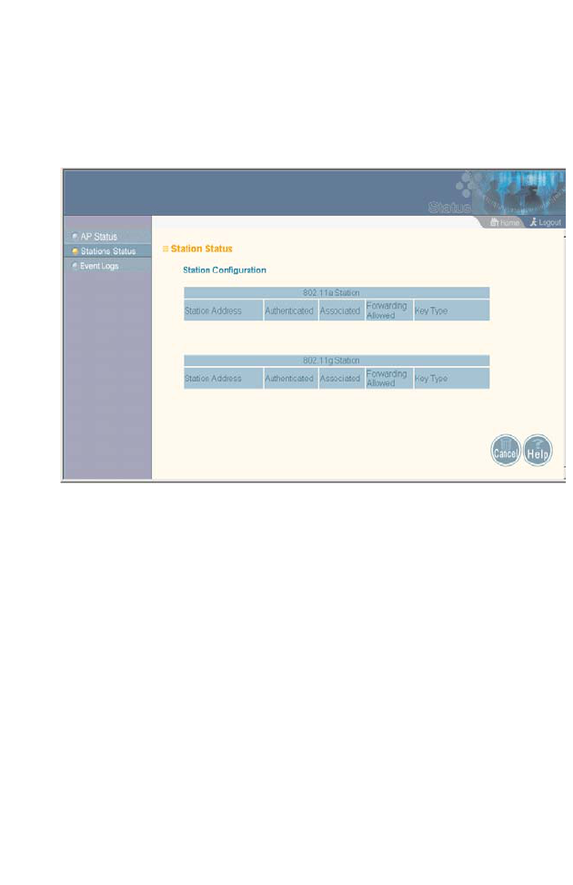
Status Information
5-69
Station Status
The Station Status window shows the wireless clients currently
associated with the access point.
The Station Configuration page displays basic connection
information for all associated stations as described below. Note
that this page is automatically refreshed every five seconds.
•Station Address: The MAC address of the wireless client.
•Authenticated: Shows if the station has been authenticated.
The two basic methods of authentication supported for 802.11
wireless networks are “open system” and “shared key.”
Open-system authentication accepts any client attempting to
connect to the access point without verifying its identity. The
shared-key approach uses Wired Equivalent Privacy (WEP) to
verify client identity by distributing a shared key to stations
before attempting authentication.

System Configuration
5-70
•Associated: Shows if the station has been successfully
associated with the access point. Once authentication is
completed, stations can associate with the current access
point, or reassociate with a new access point. The association
procedure allows the wireless system to track the location of
each mobile client, and ensure that frames destined for each
client are forwarded to the appropriate access point.
•Forwarding Allowed: Shows if the station has passed 802.1x
authentication and is now allowed to forward traffic to the
access point.
Key Type: Displays one of the following:
•Disabled: The client is not using Wired Equivalent Privacy
(WEP) encryption keys.
•Dynamic: The client is using Wi-Fi Protected Access (802.1x
or pre-shared key mode) or using 802.1x authentication with
dynamic keying.
•Static: The client is using static WEP keys for encryption.
CLI Commands for Displaying Station Status – To view status of
clients currently associated with the access point, use the show
station command from the Exec mode.
AP#show station 6-109
No 802.11a Stations.
802.11g Channel : 11
802.11g Channel Station Table
Station Address : 00-04-E2-41-C2-9D
Authenticated Associated Forwarding KeyType
TRUE TRUE TRUE DISABLED
Counters:pkts Tx / Rx bytes Tx / Rx
4/ 0 1440/ 0
==========================================================
AP#
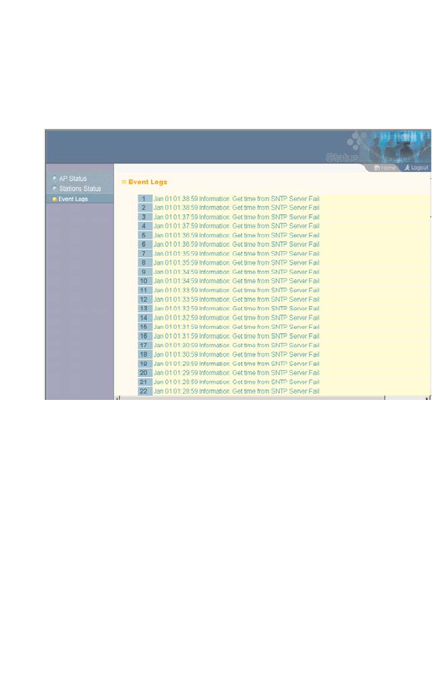
Status Information
5-71
Event Logs
The Event Logs window shows the log messages generated by
the access point and stored in memory.
The Event Logs table displays the following information:
•Log Time: The time the log message was generated.
•Event Level: The logging level associated with this message.
For a description of the various levels, see “logging level” on
page 5-36.
•Event Message: The content of the log message.
Error Messages – An example of a logged error message is:
“Station Failed to authenticate (unsupported algorithm).”
This message may be caused by any of the following conditions:
•Access point was set to “Open Authentication,” but a client
sent an authentication request frame with a “Shared key.”

System Configuration
5-72
•Access point was set to “Shared Key Authentication,” but a
client sent an authentication frame for “Open System.”
•WEP keys do not match: When the access point uses “Shared
Key Authentication,” but the key used by client and access
point are not the same, the frame will be decrypted incorrectly,
using the wrong algorithm and sequence number.
CLI Commands for Displaying the Event Logs – From the global
configuration mode, use the show logging command.
Note: Log messages are not displayed in the CLI.
AP#show loggging 6-28
Logging Information
============================================
Syslog State : Enabled
Logging Host State : Enabled
Logging Console State : Enabled
Server Domain name/IP : 192.168.1.19
Logging Level : Alert
Logging Facility Type : 16
=============================================
AP#