Accton Technology WG3004A-17 Mozart User Manual SMC7004AWBR
Accton Technology Corp Mozart SMC7004AWBR
UserManual.wiki
>
Accton Technology
>
WG3004A 17 User Manual
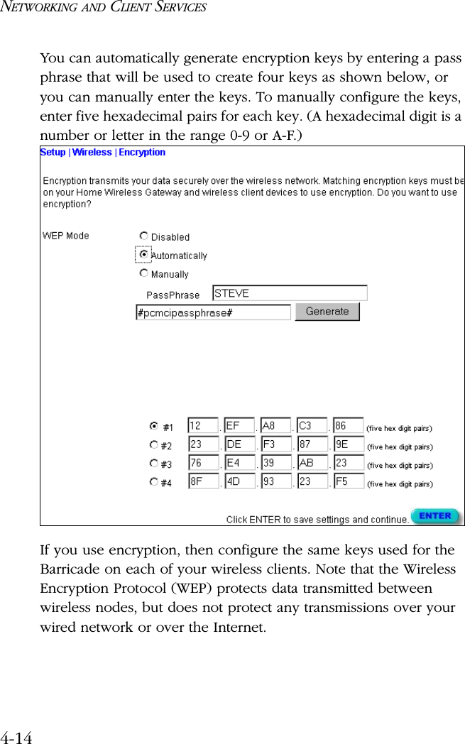
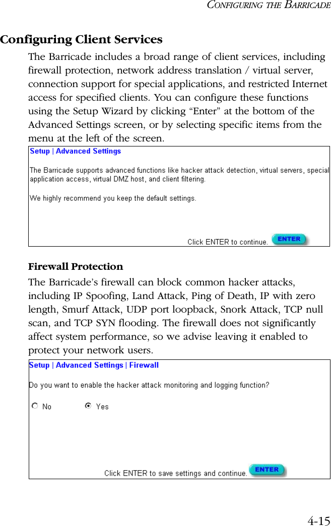
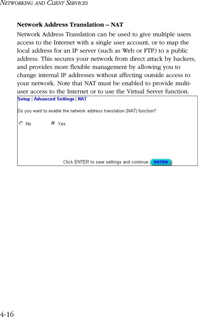
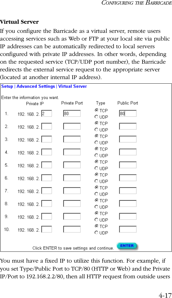
users manual
Navigation menu
Upload a User Manual
Namespaces
Wiki Guide
HTML
PDF
Info
Views
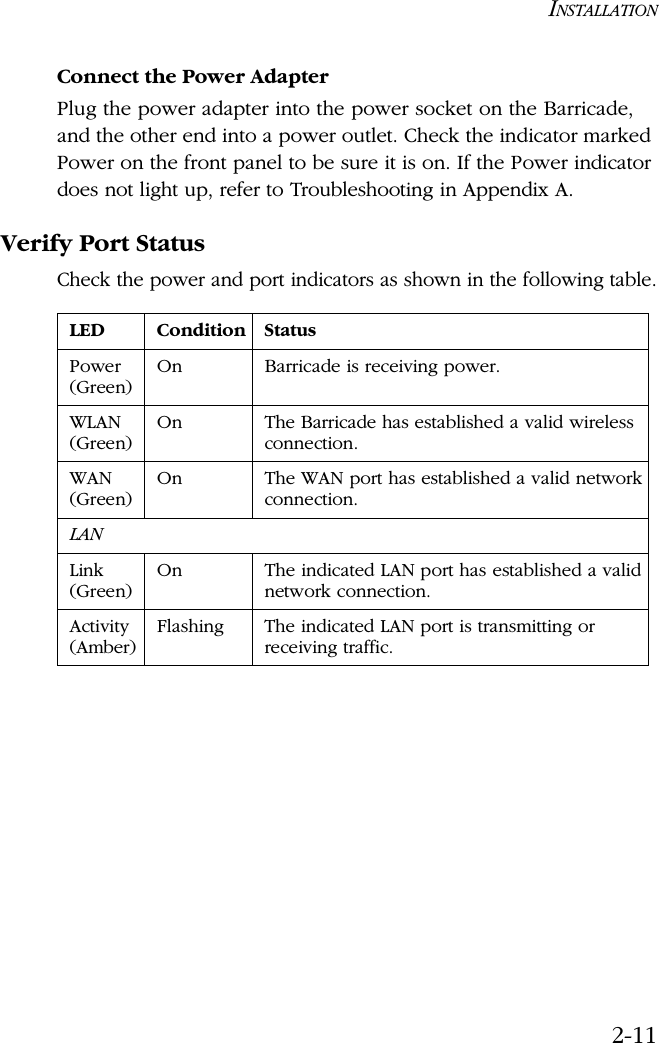
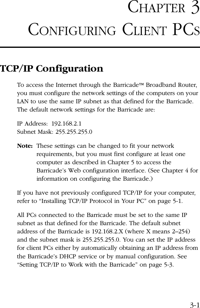
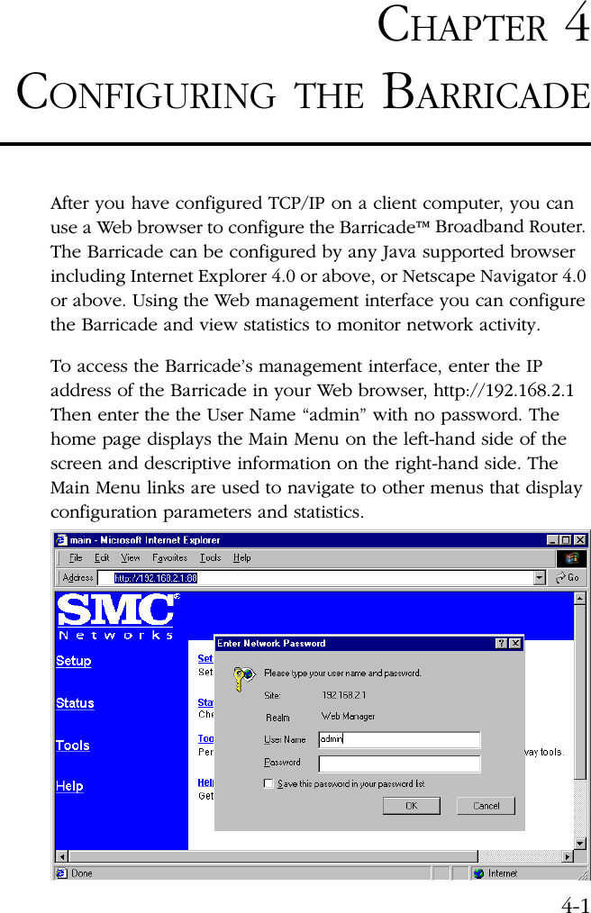
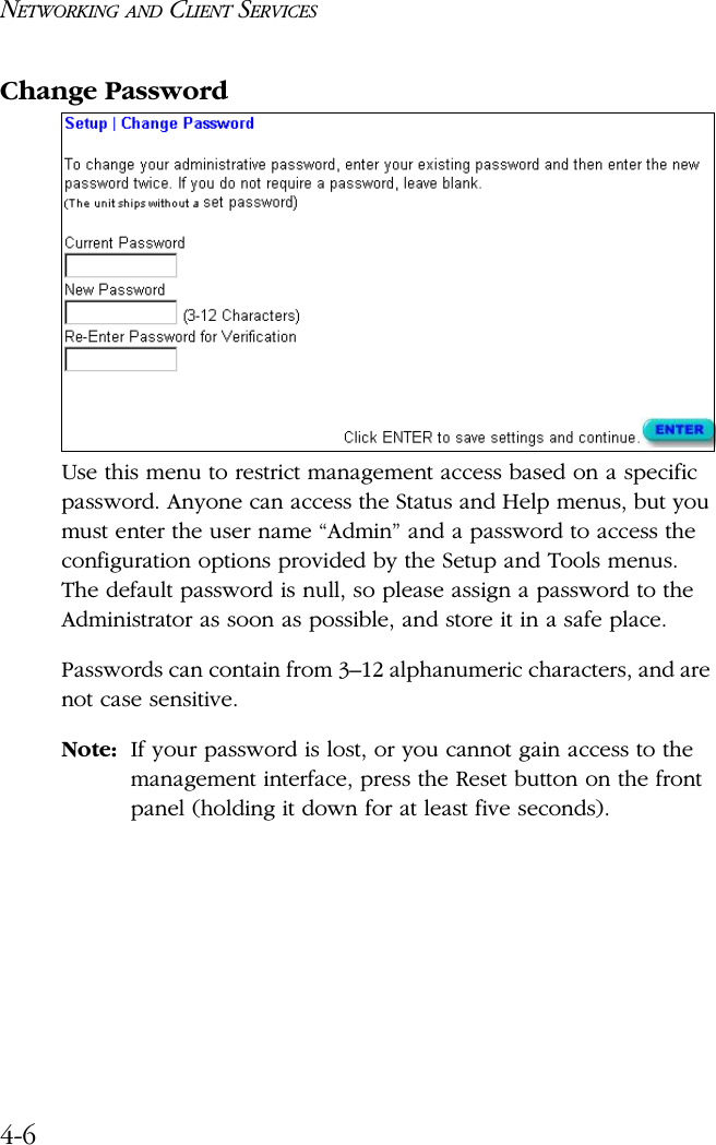
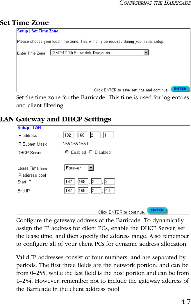
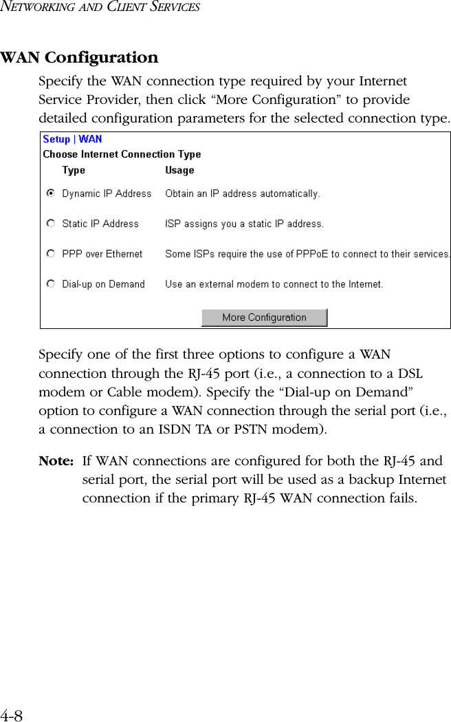
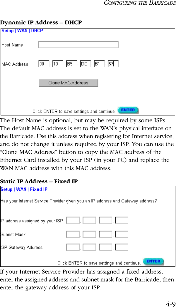
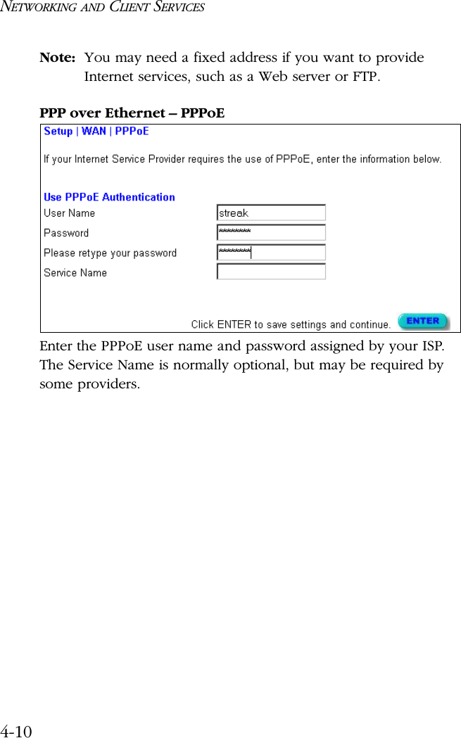
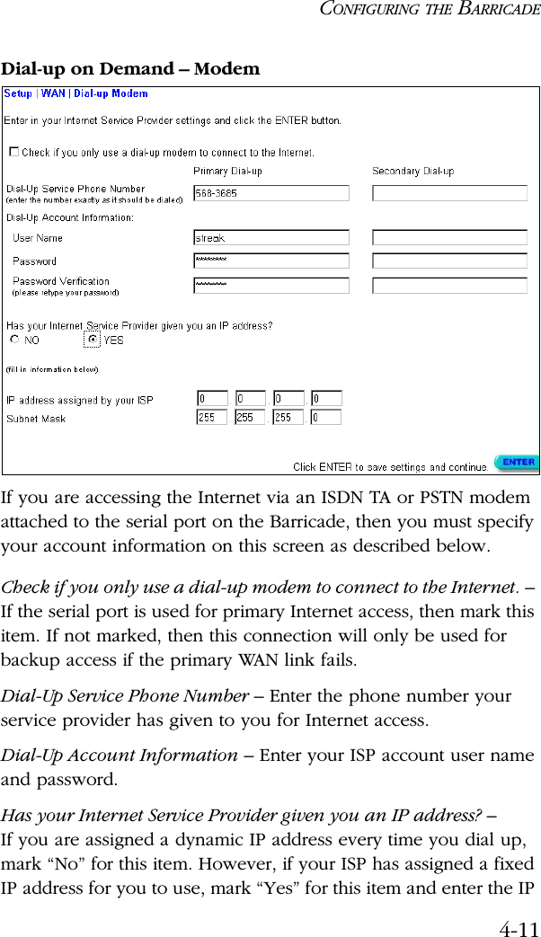
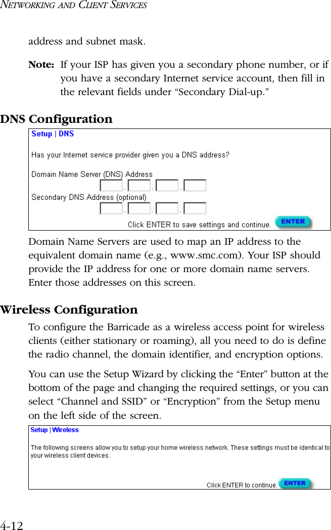
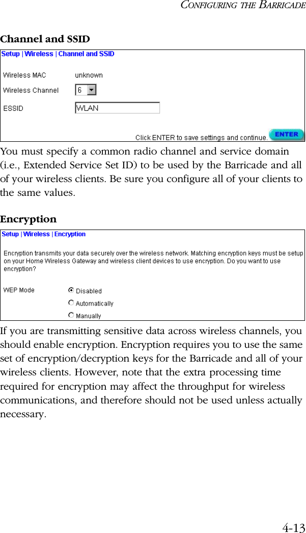
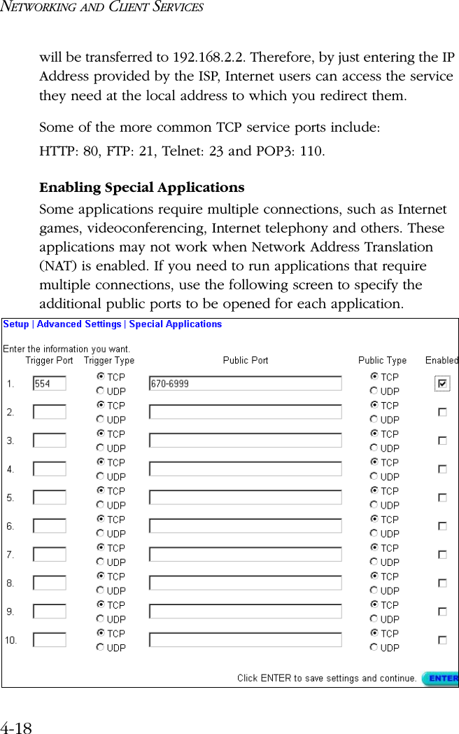
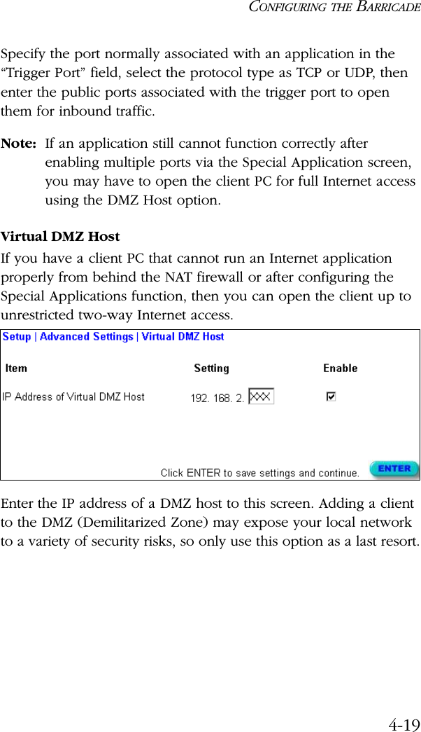
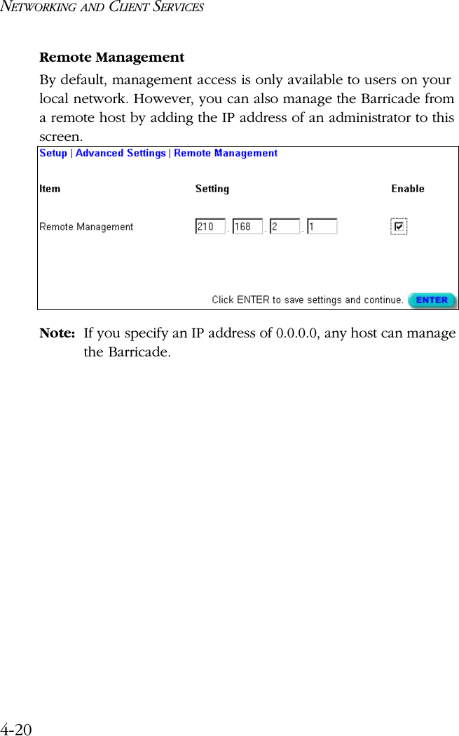
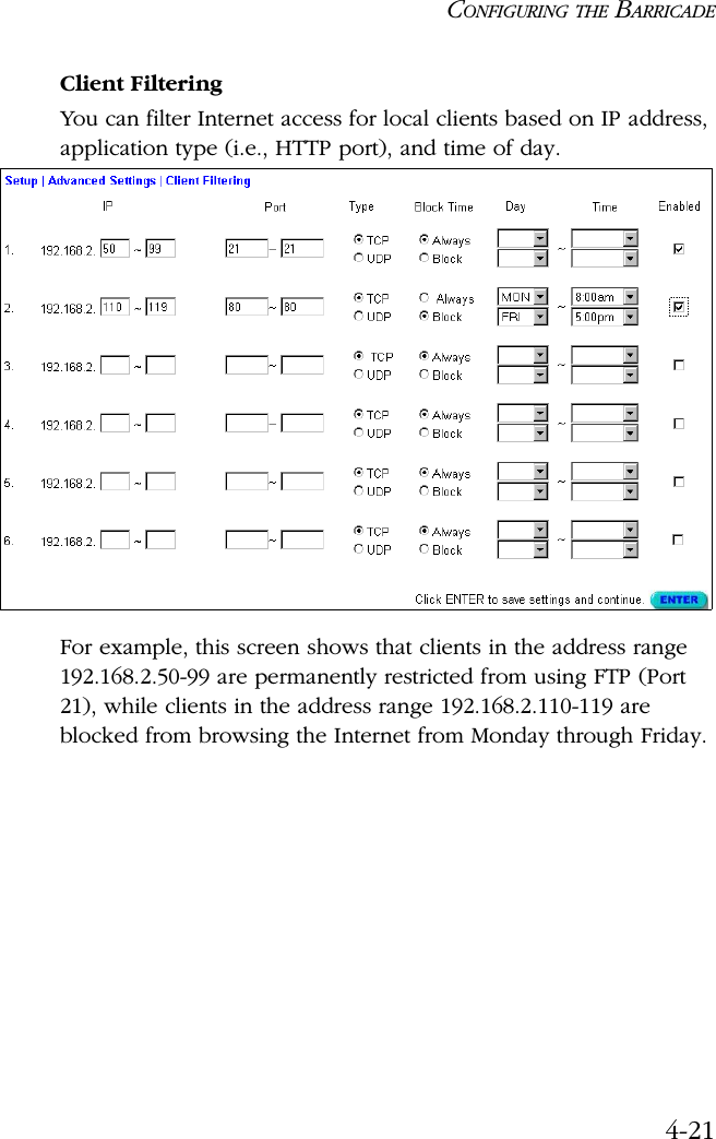
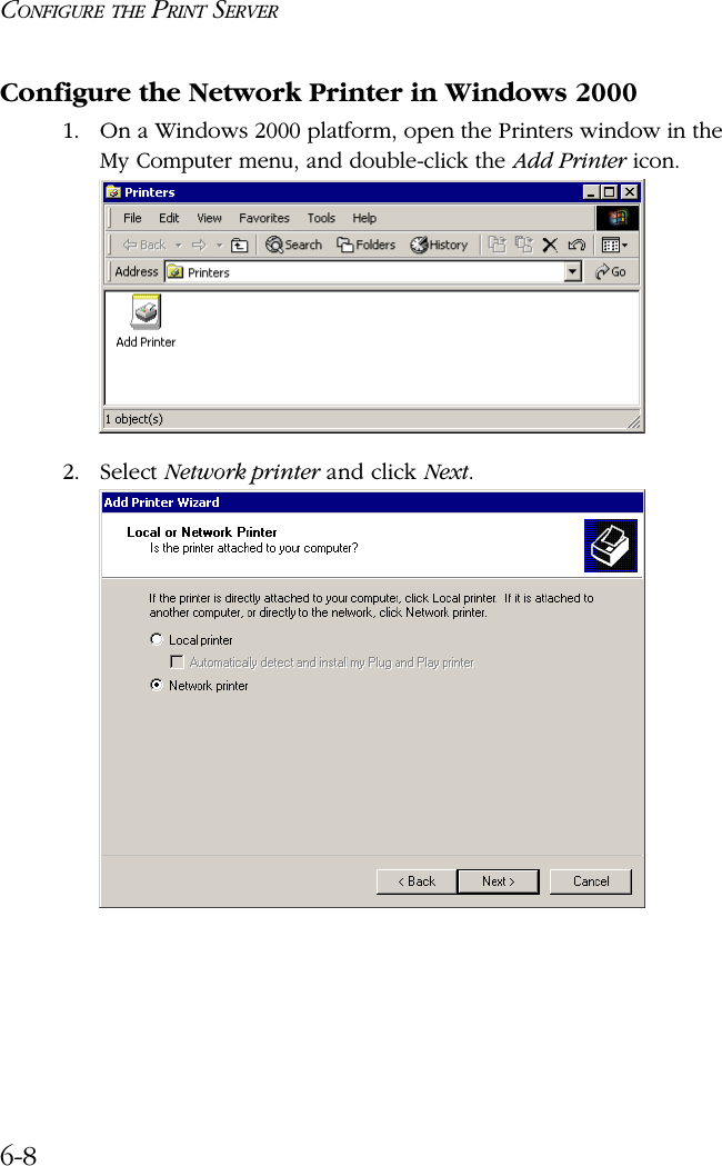
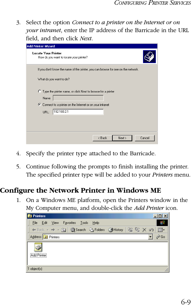
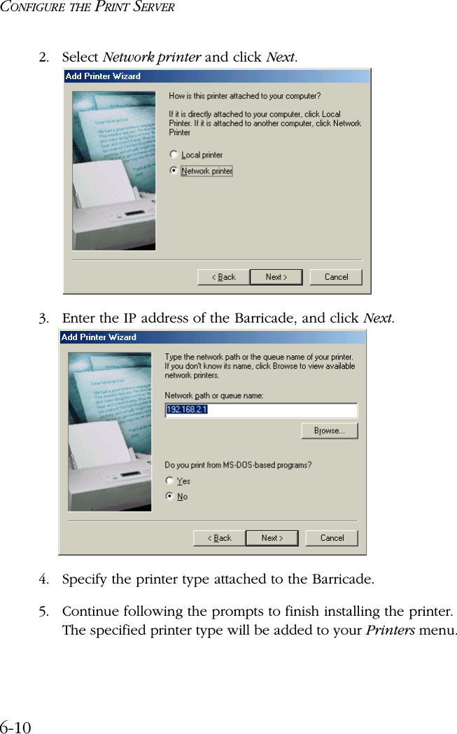
User Manual
Discussion / Help
Navigation