Accton Technology WG3004A-17 Mozart User Manual SMC7004AWBR
Accton Technology Corp Mozart SMC7004AWBR
users manual

Barricade
™
Broadband Router
Wireless Broadband Router
◆ Internet access via –
◆ 10 Mbps WAN port connection to xDSL/Cable modem, or
◆ RS232 console port connection to ISDN/PSTN modem
◆ Home networking via –
◆ Three 10/100 Mbps Ethernet switch ports, or
◆ 11 Mbps wireless interface
◆ Built-in Printer Server
◆ Automatic IP address configuration with DHCP, DNS
◆ Firewall – client privileges, hacker prevention, NAT
◆ Multi-user access (up to 253), single-user account
◆ Virtual server with network address translation
◆ Virtual Private Network using PPTP, L2TP, IPSec
User Guide
SMC7004AWBR


6 Hughes
Irvine, CA 92618
Phone: (949) 707-2400
Barricade™
Wireless Broadband Router
User Guide
From SMC’s Barricade line of Broadband Routers
May 2001
Revision Number: R01
Firmware Version 0.01

Copyright
Information furnished by SMC Networks, Inc. (SMC) is believed to be accurate and reliable.
However, no responsibility is assumed by SMC for its use, nor for any infringements of patents
or other rights of third parties which may result from its use. No license is granted by
implication or otherwise under any patent or patent rights of SMC. SMC reserves the right to
change specifications at any time without notice.
Copyright © 2001 by
SMC Networks, Inc.
6 Hughes
Irvine, CA 92618
All rights reserved. Printed in Taiwan
Trademarks:
SMC is a registered trademark; and Barricade is a trademark of SMC Networks, Inc. Other
product and company names are trademarks or registered trademarks of their respective
holders.

L
IMITED
W
ARRANTY
Limited Warranty
Limited Warranty Statement: SMC Networks, Inc. (“SMC”) warrants its products
to be free from defects in workmanship and materials, under normal use and
service, for the applicable warranty term. All SMC products carry a standard 90-day
limited warranty from the date of purchase from SMC or its Authorized Reseller.
SMC may, at its own discretion, repair or replace any product not operating as
warranted with a similar or functionally equivalent product, during the applicable
warranty term. SMC will endeavor to repair or replace any product returned under
warranty within 30 days of receipt of the product.
The standard limited warranty can be upgraded to a Limited Lifetime* warranty by
registering new products within 30 days of purchase from SMC or its Authorized
Reseller. Registration can be accomplished via the enclosed product registration
card or online via the SMC web site. Failure to register will not affect the standard
limited warranty. The Limited Lifetime warranty covers a product during the Life of
that Product, which is defined as the period of time during which the product is an
‘Active’ SMC product. A product is considered to be ‘Active’ while it is listed on the
current SMC price list. As new technologies emerge, older technologies become
obsolete and SMC will, at its discretion, replace an older product in its product line
with one that incorporates these newer technologies. At that point, the obsolete
product is discontinued and is no longer an ‘Active’ SMC product. A list of
discontinued products with their respective dates of discontinuance can be found at
http://www.smc.com/smc/pages_html/support.html
All products that are replaced become the property of SMC. Replacement products
may be either new or reconditioned. Any replaced or repaired product carries
either a 30-day limited warranty or the remainder of the initial warranty, whichever
is longer. SMC is not responsible for any custom software or firmware,
configuration information, or memory data of Customer contained in, stored on, or
integrated with any products returned to SMC pursuant to any warranty. Products
returned to SMC should have any customer-installed accessory or add-on
components, such as expansion modules, removed prior to returning the product
for replacement. SMC is not responsible for these items if they are returned with the
product.
Customers must contact SMC for a Return Material Authorization number prior to
returning any product to SMC. Proof of purchase may be required. Any product
returned to SMC without a valid Return Material Authorization (RMA) number
clearly marked on the outside of the package will be returned to customer at
customer's expense. For warranty claims within North America, please call our
toll-free customer support number at (800) 762-4968. Customers are responsible for
all shipping charges from their facility to SMC. SMC is responsible for return
shipping charges from SMC to customer.


L
IMITED
W
ARRANTY
C
OMPLIANCES
FCC - Class B
This equipment has been tested and found to comply with the limits for a Class B digital
device, pursuant to Part 15 of the FCC Rules. These limits are designed to provide rea-
sonable protection against harmful interference in a residential installation. This equip-
ment generates, uses and can radiate radio frequency energy and, if not installed and
used in accordance with instructions, may cause harmful interference to radio communi-
cations. However, there is no guarantee that the interference will not occur in a particu-
lar installation. If this equipment does cause harmful interference to radio or television
reception, which can be determined by turning the equipment off and on, the user is
encouraged to try to correct the interference by one or more of the following measures:
• Reorient the receiving antenna
• Increase the separation between the equipment and receiver
• Connect the equipment into an outlet on a circuit different from that to which the
receiver is connected
• Consult the dealer or an experienced radio/TV technician for help
EC Conformance Declaration - Class B
SMC contact for these products in Europe is:
SMC (Europe) Limited
1st Floor, Pyramid House, Easthampstead Road,
Bracknell, Berkshire RG12 1NS, United Kingdom
This information technology equipment complies with the requirements of the Low
Voltage Directive 73/23/EEC and the EMC Directive 89/336/EEC, and carries the CE
Mark accordingly. It conforms to the following specifications:
EMC: EN55022 (1988)/CISPR-22 (1995) Class B
IEC 1000-4-2 4 kV CD, 8 kV AD
IEC 1000-4-3 (1995) 3 V/m
IEC 1000-4-4 (1995) 1.0 kV - (power line)
0.5 kV - (signal line)
IEC 1000-4-6 (1995) 3 Vrms
Industry Canada - Class B
This digital apparatus does not exceed the Class B limits for radio noise emissions from
digital apparatus as set out in the interference-causing equipment standard entitled “Dig-
ital Apparatus,” ICES-003 of the Department of Communications.
Cet appareil numérique respecte les limites de bruits radioélectriques applicables aux
appareils numériques de Classe B prescrites dans la norme sur le matériel brouilleur:
“Appareils Numériques,” NMB-003 édictée par le ministère des Communications.

L
IMITED
W
ARRANTY
Japan VCCI Class B
Australia AS/NZS 3548 (1995) - Class B
SMC contact for products in Australia is:
SMC Communications Pty. Ltd.
Suite 18, 12 Tryon Road,
Lindfield NSW2070,
Phone: 61-2-94160437
Fax: 61-2-94160474
Safety Compliance
Underwriters Laboratories Compliance Statement
Important!
Before making connections, make sure you have the correct cord set.
Check it (read the label on the cable) against the following:
The unit automatically matches the connected input voltage. Therefore, no additional
adjustments are necessary when connecting it to any input voltage within the range
marked on the rear panel.
Operating Voltage Cord Set Specifications
120 Volts UL Listed/CSA Certified Cord Set
Minimum 18 AWG
Type SVT or SJT three conductor cord
Maximum length of 15 feet
Parallel blade, grounding type attachment plug
rated 15A, 125V
240 Volts (Europe only) Cord Set with H05VV-F cord having three
conductors with minimum diameter of 0.75
mm2
IEC-320 receptacle
Male plug rated 10A, 250V

L
IMITED
W
ARRANTY
Wichtige Sicherheitshinweise (Germany)
1. Bitte lesen Sie diese Hinweise sorgfältig durch.
2. Heben Sie diese Anleitung für den späteren Gebrauch auf.
3. Vor jedem Reinigen ist das Gerät vom Stromnetz zu trennen. Verwenden Sie keine
Flüssigoder Aerosolreiniger. Am besten eignet sich ein angefeuchtetes Tuch zur
Reinigung.
4. Die Netzanschlu ßsteckdose soll nahe dem Gerät angebracht und leicht zugänglich
sein.
5. Das Gerät ist vor Feuchtigkeit zu schützen.
6. Bei der Aufstellung des Gerätes ist auf sicheren Stand zu achten. Ein Kippen oder
Fallen könnte Beschädigungen hervorrufen.
7. Die Belüftungsöffnungen dienen der Luftzirkulation, die das Gerät vor Überhitzung
schützt. Sorgen Sie dafür, daß diese Öffnungen nicht abgedeckt werden.
8. Beachten Sie beim Anschluß an das Stromnetz die Anschlußwerte.
9. Verlegen Sie die Netzanschlußleitung so, daß niemand darüber fallen kann. Es sollte
auch nichts auf der Leitung abgestellt werden.
10. Alle Hinweise und Warnungen, die sich am Gerät befinden, sind zu beachten.
11. Wird das Gerät über einen längeren Zeitraum nicht benutzt, sollten Sie es vom
Stromnetz trennen. Somit wird im Falle einer Überspannung eine Beschädigung ver-
mieden.
12. Durch die Lüftungsöffnungen dürfen niemals Gegenstände oder Flüssigkeiten in das
Gerät gelangen. Dies könnte einen Brand bzw. elektrischen Schlag auslösen.
13. Öffnen sie niemals das Gerät. Das Gerät darf aus Gründen der elektrischen Sicher-
heit nur von authorisiertem Servicepersonal geöffnet werden.
14. Wenn folgende Situationen auftreten ist das Gerät vom Stromnetz zu trennen und
von einer qualifizierten Servicestelle zu überprüfen:
a. Netzkabel oder Netzstecker sind beschädigt.
b. Flüssigkeit ist in das Gerät eingedrungen.
c. Das Gerät war Feuchtigkeit ausgesetzt.
d. Wenn das Gerät nicht der Bedienungsanleitung entsprechend funktioniert oder
Sie mit Hilfe dieser Anleitung keine Verbesserung erzielen.
e. Das Gerät ist gefallen und/oder das Gehäuse ist beschädigt.
f. Wenn das Gerät deutliche Anzeichen eines Defektes aufweist.
15. Stellen Sie sicher, da? die Stromversorgung dieses Ger‰tes nach der EN 60950
gepr¸ft ist. Ausgangswerte der Stromversorgung sollten die Werte von AC 7,5-8V,
50-60Hz nicht ¸ber oder unterschreiten sowie den minimalen Strom von 1A nicht
unterschreiten..
Der arbeitsplatzbezogene Schalldruckpegel nach DIN 45 635 Teil 1000 beträgt 70dB(A)
oder weniger.

L
IMITED
W
ARRANTY

xi
T
ABLE
OF
C
ONTENTS
1 Introduction . . . . . . . . . . . . . . . . . . . . . . . . . . . . 1-1
About the Barricade . . . . . . . . . . . . . . . . . . . . . . . . . . . . . . . . 1-1
Features and Benefits . . . . . . . . . . . . . . . . . . . . . . . . . . . . . . . 1-2
Applications . . . . . . . . . . . . . . . . . . . . . . . . . . . . . . . . . . . . . 1-3
2 Installation . . . . . . . . . . . . . . . . . . . . . . . . . . . . . . 2-1
Package Contents . . . . . . . . . . . . . . . . . . . . . . . . . . . . . . . . . 2-1
Description of Hardware . . . . . . . . . . . . . . . . . . . . . . . . . . . . 2-2
System Requirements . . . . . . . . . . . . . . . . . . . . . . . . . . . . . . . 2-5
Connect the System . . . . . . . . . . . . . . . . . . . . . . . . . . . . . . . . 2-6
Basic Installation Procedure . . . . . . . . . . . . . . . . . . . . . 2-6
Attach to Your Network Using Ethernet Cabling . . . 2-7
Attach to Your Network Using Radio Signals . . . . . . 2-8
Attach the Barricade to the Internet . . . . . . . . . . . . 2-10
Connect a Printer . . . . . . . . . . . . . . . . . . . . . . . . . 2-10
Connect the Power Adapter . . . . . . . . . . . . . . . . . 2-11
Verify Port Status . . . . . . . . . . . . . . . . . . . . . . . . . . . . 2-11
3 Configuring Client PCs . . . . . . . . . . . . . . . . . . . . 3-1
TCP/IP Configuration . . . . . . . . . . . . . . . . . . . . . . . . . . . . . . . 3-1
Printer Client Installation . . . . . . . . . . . . . . . . . . . . . . . . . . . . 3-2
4 Configuring the Barricade . . . . . . . . . . . . . . . . . 4-1
Navigating the Web Browser Interface . . . . . . . . . . . . . . . . . . 4-2
Setting a Password . . . . . . . . . . . . . . . . . . . . . . . . . . . . 4-2
Making Configuration Changes . . . . . . . . . . . . . . . . . . . 4-2
Main Menu . . . . . . . . . . . . . . . . . . . . . . . . . . . . . . . . . . . . . . 4-3
Networking and Client Services . . . . . . . . . . . . . . . . . . . . . . . 4-5
Change Password . . . . . . . . . . . . . . . . . . . . . . . . . . . . . 4-6
Set Time Zone . . . . . . . . . . . . . . . . . . . . . . . . . . . . . . . 4-7
LAN Gateway and DHCP Settings . . . . . . . . . . . . . . . . . 4-7
WAN Configuration . . . . . . . . . . . . . . . . . . . . . . . . . . . 4-8
Dynamic IP Address – DHCP . . . . . . . . . . . . . . . . . 4-9
Static IP Address – Fixed IP . . . . . . . . . . . . . . . . . . 4-9
PPP over Ethernet – PPPoE . . . . . . . . . . . . . . . . . . 4-10
Dial-up on Demand – Modem . . . . . . . . . . . . . . . 4-11

T
ABLE
OF
C
ONTENTS
xii
DNS Configuration . . . . . . . . . . . . . . . . . . . . . . . . . . 4-12
Wireless Configuration . . . . . . . . . . . . . . . . . . . . . . . . 4-12
Channel and SSID . . . . . . . . . . . . . . . . . . . . . . . . 4-13
Encryption . . . . . . . . . . . . . . . . . . . . . . . . . . . . . 4-13
Configuring Client Services . . . . . . . . . . . . . . . . . . . . 4-15
Firewall Protection . . . . . . . . . . . . . . . . . . . . . . . 4-15
Network Address Translation – NAT . . . . . . . . . . 4-16
Virtual Server . . . . . . . . . . . . . . . . . . . . . . . . . . . 4-17
Enabling Special Applications . . . . . . . . . . . . . . . 4-18
Virtual DMZ Host . . . . . . . . . . . . . . . . . . . . . . . . 4-19
Remote Management . . . . . . . . . . . . . . . . . . . . . . 4-20
Client Filtering . . . . . . . . . . . . . . . . . . . . . . . . . . 4-21
Viewing Network and Device Status . . . . . . . . . . . . . . . . . . 4-22
Using System Tools . . . . . . . . . . . . . . . . . . . . . . . . . . . . . . . 4-23
5 Configuring Client TCP/IP . . . . . . . . . . . . . . . . . . 5-1
Installing TCP/IP Protocol in Your PC . . . . . . . . . . . . . . . . . . 5-1
Setting TCP/IP to Work with the Barricade . . . . . . . . . . . . . . 5-3
Dynamic IP Allocation via a DHCP Server . . . . . . . . . . 5-4
Manual IP Configuration . . . . . . . . . . . . . . . . . . . . . . . 5-5
Verifying Your TCP/IP Connection . . . . . . . . . . . . . . . . 5-6
6 Configuring Printer Services . . . . . . . . . . . . . . . . 6-1
Install the Printer Port Monitor . . . . . . . . . . . . . . . . . . . . . . . 6-1
Configure the Print Server . . . . . . . . . . . . . . . . . . . . . . . . . . . 6-4
Configure the Network Printer in Windows 95/98 . . . . . 6-4
Configure the Network Printer in Windows NT . . . . . . . 6-6
Configure the Network Printer in Windows 2000 . . . . . 6-8
Configure the Network Printer in Windows ME . . . . . . . 6-9
Configure the Network Printer in Unix Systems . . . . . 6-11

T
ABLE
OF
C
ONTENTS
xiii
APPENDICES:
A Troubleshooting . . . . . . . . . . . . . . . . . . . . . . . . . .A-1
Diagnosing Gateway Indicators . . . . . . . . . . . . . . . . . . . . . . . A-1
B Cables . . . . . . . . . . . . . . . . . . . . . . . . . . . . . . . . . .B-1
Ethernet Cable . . . . . . . . . . . . . . . . . . . . . . . . . . . . . . . . . . . B-1
Specifications . . . . . . . . . . . . . . . . . . . . . . . . . . . . . . . B-1
Twisted-Pair Cable and Pin Assignments . . . . . . . . . . . . B-1
10BASE-T/100BASE-TX Pin Assignments . . . . . . . . . . . . B-2
Straight-Through Wiring . . . . . . . . . . . . . . . . . . . . B-3
Crossover Wiring . . . . . . . . . . . . . . . . . . . . . . . . . . B-3
Serial Port Pin Assignments . . . . . . . . . . . . . . . . . . . . . . . . . . B-4
DB-9 Port Pin Assignments . . . . . . . . . . . . . . . . . . . . . B-4
Serial Port to 9-Pin COM Port on PC . . . . . . . . . . . . . . . B-5
Serial Port to 25-Pin DCE Port on Modem . . . . . . . . . . . B-5
Serial Port to 25-Pin DTE Port on PC . . . . . . . . . . . . . . B-5
Printer Port Pin Assignments . . . . . . . . . . . . . . . . . . . . . . . . . B-6
DB-25 Printer Port Pin Assignments . . . . . . . . . . . . . . . B-6
C Specifications . . . . . . . . . . . . . . . . . . . . . . . . . . . .C-1
D Ordering Information . . . . . . . . . . . . . . . . . . . . D-1

T
ABLE
OF
C
ONTENTS
xiv

1-1
C
HAPTER
1
I
NTRODUCTION
Congratulations on your purchase of the Barricade™ Wireless
Broadband Router. SMC is proud to provide you with a powerful
yet simple communication device for connecting your local area
network (wired or wireless LAN) to the Internet. For those who
want to surf on the Internet at the lowest possible cost, this
Broadband Router provides a convenient and powerful solution.
About the Barricade
The Barricade provides Internet access to multiple users by sharing
a single-user account. The Barricade’s most outstanding features
include wireless LAN connectivity, as well as the
dual-port WAN
interface which allows you to connect to an xDSL or Cable
modem,
ISDN TA or PSTN analog modem. The
Barricade
provides
extensive
firewall protection and Virtual Private Network (VPN) services. It
also provides print services for any client attached to a LAN port.
The Barricade supports dial-on-demand for ISDN/PSTN service,
automatically connecting to the Internet when there are requests
and terminating the connection if no further requests occur. This
dual-port design also supports fail-over Internet access through the
secondary WAN port (i.e., the serial port can be used for primary
or backup Internet access).
This new Barricade technology provides many cost-effective
functions and management benefits. It is simple to configure and
can be up and running in minutes.

F
EATURES
AND
B
ENEFITS
1-2
Features and Benefits
•Internet connection to xDSL or Cable modem via 10 Mbps WAN
port
•Internet connection to ISDN TA or PSTN modem via RS232
console port
•Local network connection via 10/100 Mbps Ethernet ports or
11 Mbps wireless interface (supporting up to 20 mobile users)
•Print services for any client attached to the LAN
•DHCP for dynamic IP configuration, and DNS for domain name
mapping
•Firewall with client privileges, hacker prevention, and NAT
•NAT also enables multi-user access with a single-user account,
and virtual server functionality (providing protected access to
Internet services such as Web, FTP, mail and Telnet)
•Virtual Private Network using PPTP, L2TP or IPSec
•User-definable application sensing tunnel supports applications
requiring multiple connections
•Supports CHAP authentication protocol for dial-up
identification
•Supports PPP dial-in connection using standard dial-up
program
•Easy setup through a Web browser on any operating system
that supports TCP/IP
•Compatible with all popular Internet applications

I
NTRODUCTION
1-3
Applications
Many advanced applications are provided by the Barricade, such as:
•Flexible LAN Access
The Barricade provides connectivity to 10/100 Mbps wired
devices as well as 11 Mbps wireless mobile users. The wireless
interface makes it easy to create a network in difficult-to-wire
environments, or to provide quick access to databases for
mobile workers.
• Internet Access
This device supports Internet access through an xDSL, Cable,
ISDN or PSTN connection. Since many DSL providers use
PPPoE to establish communications with end users, the
Barricade includes a built-in client for this protocol,
eliminating the need to install this service on your computer.
• Shared IP Address
The Barricade provides Internet access for up to 253 users
with a shared IP address. Using only one ISP account, multiple
users on your network can browse the Web at the same time.
• Virtual Server
If you have a fixed IP address, you can set up the Barricade to
act as a virtual host for network address translation. Remote
users access various services at your site using a constant IP
address. Then, depending on the requested service (or port
number), the Barricade can route the request to the
appropriate server (at another internal IP address). This
secures your network from direct attack by hackers, and
provides more flexible management by allowing you to
change internal IP addresses without affecting outside access
to your network.

A
PPLICATIONS
1-4
• User-Definable Application Sensing Tunnel
You can define special applications that require multiple
connections such as Internet gaming, video conferencing, and
Internet telephony. The Barricade can then sense the
application type and open a multi-port tunnel for it.
• DMZ Host Support
Allows a networked computer to be fully exposed to the
Internet. This function is used when the special application
sensing tunnel feature is insufficient to allow an application to
function correctly.
• Security
The Barricade supports security features that can deny Internet
access to specified users, or filter all requests for specific
services the administrator does not want to serve. The
Barricade’s firewall can also block common hacker attacks,
including IP Spoofing, Land Attack, Ping of Death, IP with
zero length, Smurf Attack, UDP port loopback, Snork Attack,
TCP null scan, and TCP SYN flooding.
• Virtual Private Network
The Barricade supports three of the most commonly used VPN
protocols – PPTP, L2TP and IPSec. These protocols allow
remote users to establish a secure connection to their
corporate network. If your service provider supports VPNs,
then any of these protocols can be used to create an
authenticated and encrypted tunnel for passing secure data
over the Internet (i.e., a traditionally shared data network).
The VPN protocols supported by the Barricade are briefly
described below.

I
NTRODUCTION
1-5
•Point-to-Point Tunneling Protocol – Provides a secure
tunnel for remote client access to a PPTP security gateway.
PPTP includes provisions for call origination and flow
control required by ISPs.
•Layer Two Tunneling Protocol – Includes most of the
features provided by PPTP, but has less overhead and is
more suited for managed networks.
•IP Security – Provides IP network-layer encryption. IPSec
can support large encryption networks (such as the
Internet) by using digital certificates for device
authentication.

A
PPLICATIONS
1-6

2-1
C
HAPTER
2
I
NSTALLATION
Before installing the Barricade™ Wireless Broadband Router, verify
that you have all the items listed under “Package Contents.” If any
of the items are missing or damaged, contact your local SMC
distributor. Also be sure you have all the necessary cabling before
installing the gateway. After installing the Barricade, refer to the
Web-based configuration program in Chapter 3 for information on
configuring the router.
Package Contents
After unpacking the Barricade broadband router, check the
contents of the box to be sure you’ve received the following
components:
•Barricade 10/100 Mbps Wireless Broadband Router
•Power Adapter (5V,2.4A)
•One CAT-5 Ethernet Cable
•Four rubber feet
•Installation CD
•Quick Installation Guide
•SMC Warranty Registration Card
Immediately inform your dealer in the event of any incorrect,
missing or damaged parts. If possible, please retain the carton and
original packing materials in case there is a need to return the
product.

I
NSTALLATION
2-2
Please fill out and return the Warranty Registration Card to SMC or
register on SMC’s Web site. The Barricade Broadband Router is
covered by a limited lifetime warranty.
Description of Hardware
The Barricade Wireless Broadband Router can be connected to the
Internet or to a remote site using its RJ-45 WAN port or RS232
console port. It can be connected directly to your PC or to a local
area network using any of the three Fast Ethernet LAN ports or
through the wireless interface. It can even function as a print server.
Access speed to the Internet depends on your service type.
Full-rate ADSL can provide up to 8 Mbps downstream and 640
Mbps upstream. G.lite (or splitterless) ADSL provides up to 1.5
Mbps downstream and 512 Kbps upstream. Cable modems can
provide up to 36 Mbps downstream and 2 Mbps upstream. ISDN
can provide up to 128 Kbps when using two bearer channels. And
PSTN analog connections can now run up to 56 Kbps. However,
you should note that the actual rate provided by specific service
providers may vary dramatically from these upper limits.
Although access speed to the Internet is determined by the modem
type connected to your Barricade, data passing between devices
connected to your local area network can run up to 100 Mbps over
the Fast Ethernet ports.
The Barricade includes an LED display on the front panel for
system power and port indications that simplifies installation and
network troubleshooting. It also provides three RJ-45 LAN ports on
the front panel; as well as one RJ-45 WAN port, one RS-232 serial
port, one parallel printer port, and two antennas on the rear panel.

I
NSTALLATION
2-3
•Three RJ-45 ports for connection to a 10BASE-T/100BASE-TX
Ethernet Local Area Network (LAN). These ports can auto-
negotiate operating speed to 10/100 Mbps, the mode to half/
full duplex, and the wiring type to MDI/MDI-X (i.e., crossover
or straight-through cable). These ports can be connected
directly to a PC or to a server equipped with an Ethernet
network interface card, or to a networking device such as an
Ethernet hub or switch.
•One RJ-45 port for connection to an xDSL or Cable modem.
This port is fixed at 10 Mbps, full duplex.
•One RS-232 serial port to connect to an ISDN Terminal Adapter
(TA) or to a PSTN analog modem.
•One parallel printer port that can be connected to a printer.
This printer can then be shared by any LAN/WLAN users.
•Two antennas (dipole, omni-directional) that support
connections for up to 20 mobile users.
I
NSTALLATION
2-4
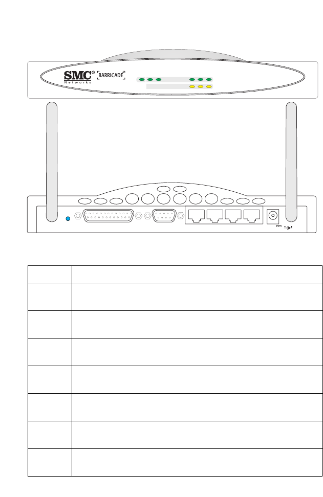
The following figure shows the components of the Barricade:
Figure 2-1. Front and Rear Panels
Item Description
LEDs Power, WLAN, WAN and LAN port status indicators.
(See Verify Port Status on page 2-11.)
Wireless
Antennas
Dual antennas provide optimal reception by dynamically
choosing the best antenna for each client.
Reset
Button
Use this button to reset the power and restore the default
factory settings.
Printer
Port
Parallel port (25-pins, D-type, female). Connect the shared
printer to this port.
COM
Port
Serial port (9-pins, D-type, male). Connect your ISDN TA or
56K analog modem to this port.
WAN
Port
WAN port (RJ-45). Connect your Cable modem, xDSL modem,
or an Ethernet router to this port.
LAN
Ports
Fast Ethernet ports (RJ-45). Connect devices on your local area
network to these ports (such as a PC, hub or switch).
SMC7004AWBR
LAN 1PWR WLAN WAN 23
Link
Activity
RESET PRINTER COM WAN 123
5V
2A MAX

I
NSTALLATION
2-5
System Requirements
You must have access to an xDSL network that meets the
following minimum requirements:
•Internet access from your local telephone company or Internet
Service Provider (ISP) using an xDSL modem, Cable modem,
ISDN TA, or PSTN analog modem. You may also have access
over the telephone system to an analog modem at another site.
•A PC using a fixed IP address or dynamic IP address assignment
via DHCP, as well as a Gateway server address and DNS server
address from your service provider.
•For wired LAN connection, you need a computer equipped
with a 10Mbps, 100Mbps, or 10/100Mbps Fast Ethernet card, or
a USB-to-Ethernet converter. For wireless LAN connections,
each computer must have an 11 Mbps wireless adapter.
•TCP/IP network protocol installed on each PC that needs to
access the Internet Gateway.
•A Java-enabled Web browser, such as Microsoft Internet
Explorer 5.0 or above or Netscape Communicator 4.0 or above
installed on one PC at your site for configuring the Barricade.
Power
Inlet
Connect the included power adapter to this inlet.
Warning: The included power adapter is DC 5V/2.4A. Using
the wrong type of power adapter may cause damage.
Item Description

I
NSTALLATION
2-6
Connect the System
The Barricade can be positioned at any convenient location in
your office or home. No special wiring or cooling requirements are
needed. You should, however comply with the following
guidelines:
•Keep the Barricade away from any heating devices.
•Do not place the Barricade in a dusty or wet environment.
You should also remember to turn off the power, remove the
power cord from the outlet, and keep your hands dry when you
install the Barricade.
Basic Installation Procedure
1. Connect the LAN: You can connect the Barricade to your PC,
or to a hub or switch. Run Ethernet cable
from one of the LAN
ports on the rear of the Barricade to
your computer’s
network
adapter or to another network device.
You can also connect the Barricade to your PC or to a wireless
access point via radio signals. Twist both antennas on the back
of the Barricade into the desired positions. For more effective
coverage, you may want to position one antenna along the
vertical axis and the other antenna along the horizontal axis.
2. Connect the WAN: Prepare an Ethernet cable for connecting
the
Barricade to a Cable/xDSL modem or Ethernet router.
Prepare a serial
cable for connecting the Barricade to an ISDN
TA or PSTN modem.
3. Connect your printer: Use standard parallel printer cable to
connect your printer to the printer port on the Barricade.
I
NSTALLATION
2-7
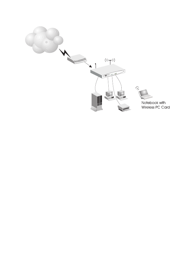
4. Power on: Connect the power adapter to the Barricade.
Figure 2-2. Connecting the Barricade
Attach to Your Network Using Ethernet Cabling
The three LAN ports on the Barricade can auto-negotiate the
connection speed to 10 Mbps Ethernet or 100 Mbps Fast Ethernet,
as well as the transmission mode to half-duplex or full-duplex.
These LAN ports also support auto-configuration for cable wiring
(auto-MDI/MDI-X) that allows you to use either straight-through
cable for connecting the gateway to any network device. (See
Appendix B for details on wiring.)
Use twisted-pair cable to connect any of the three LAN ports on
the Barricade to an Ethernet adapter on your PC. Otherwise, you
can cascade any of LAN ports on the Barricade to an Ethernet hub
or switch, and then connect your PC or other network equipment
to the hub or switch. When inserting an RJ-45 plug, be sure the tab
on the plug clicks into position to ensure that it is properly seated.
Internet
Internet
Access
Device
SMC7004AWBR
Broadband Router
SOHO Office or Residence
SMC7004AWBR
LAN1PWRWLAN WAN 23
Link
Activity
I
NSTALLATION
2-8
Warning: Do not plug a phone jack connector into any RJ-45
port. This may damage the gateway. Instead, use only
twisted-pair cables with RJ-45 connectors that conform
with FCC standards.
Notes: 1. Use 100-ohm shielded or unshielded twisted-pair cable
with RJ-45 connectors for all connections. Use Category
3, 4 or 5 for connections that operate at 10 Mbps, and
Category 5 for connections that operate at 100 Mbps.
2. Make sure each twisted-pair cable does not exceed 100
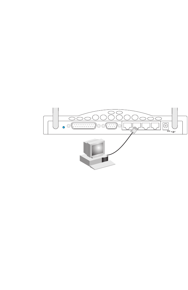
meters (328 feet).
Figure 2-3. Making LAN Connections
Attach to Your Network Using Radio Signals
Install a wireless network adapter in each computer that will be
connected to the Internet or your local network via radio signals.
SMC currently offers several wireless network cards, including the
SMC2602W PCI card and the SMC2652W PC card.
Rotate both antennas on the back of the Barricade to an upright
position. Try to place the Barricade in a position that is located in
the center of your wireless network. Normally, the higher you
place the antenna, the better the performance. Ensure that the
Barricade’s location provides optimal reception throughout your
home or office.
RESET PRINTER COM WAN 123
5V
2A MAX
I
NSTALLATION
2-9
Computers equipped with a wireless adapter can communicate
with each other as an independent wireless LAN by configuring
each computer to the same radio channel. However, the Barricade
can provide access to your wired/wireless LAN or to the Internet
for all wireless workstations. Each wireless PC in this network
infrastructure can talk to any computer in the wireless group via a
radio link, or access other computers or network resources in the
wired LAN infrastructure or over the Internet via the Barricade.
The wireless infrastructure configuration not only extends the
accessibility of wireless PCs to the wired LAN, but also doubles the
effective wireless transmission range for wireless PCs by
retransmitting incoming signals through the Barricade.
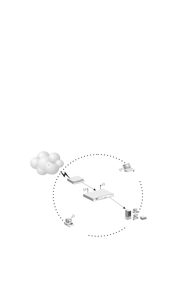
A wireless infrastructure can be used for access to a central
database, or for connection between mobile workers, as shown in
the following figure:
Figure 2-4. Making WLAN Connections
Internet
Internet
Access
Device
SMC7004AWBR
Broadband Router
Notebook with Wireless
PC Card Adapter
PC with Wireless
PCI Adapter
Wired LAN
Wired to Wireless
Network Extension
SMC7004AWBR
LAN1
PWRWLAN WAN 23
Link
Activity
I
NSTALLATION
2-10
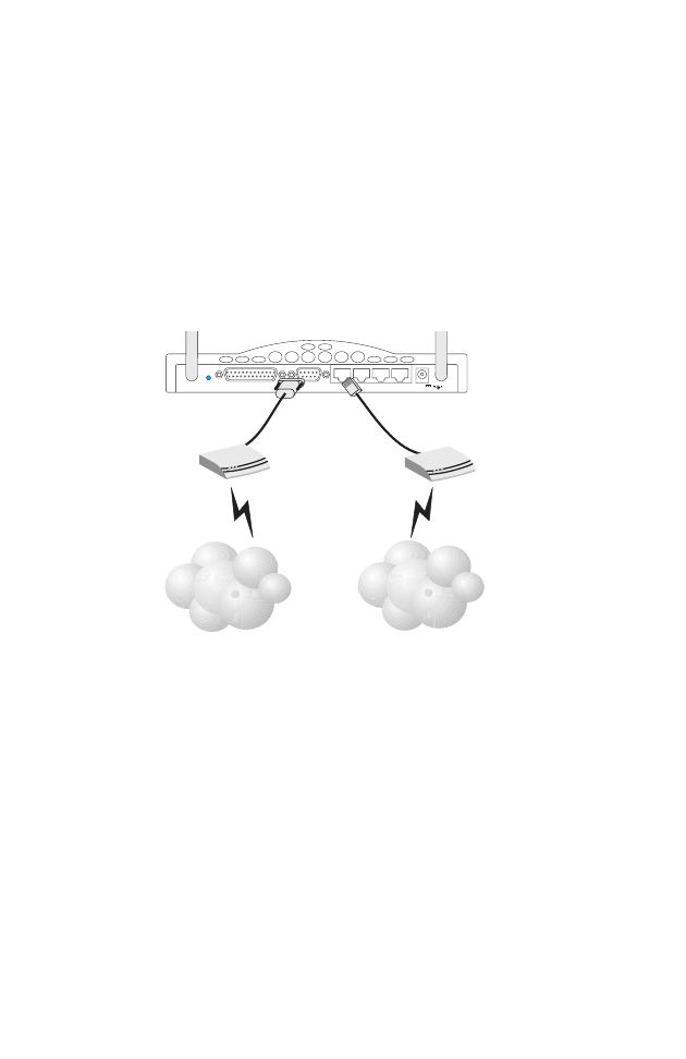
Attach the Barricade to the Internet
If Internet services are provided through an xDSL or Cable
modem, use unshielded or shielded twisted-pair Ethernet cable
(Category 3 or greater) with RJ-45 plugs to connect the broadband
modem directly to the WAN port on the Internet gateway. Use
either straight-through or crossover cable depending on the port
type provided by the modem (see Appendix B).
For ISDN
or PSTN
service, attach the access device to the RS232 serial port on the
Barricade.
Figure 2-5. Making WAN Connections
Note: When connecting to the WAN port, use 100-ohm Category
3, 4 or 5 shielded or unshielded twisted-pair cable with
RJ-45 connectors at both ends for all connections.
Connect a Printer
If you connect a printer to the Barricade, all the computer users
connected to your LAN can access print services. Connect standard
parallel printer cable to the Printer port on the Barricade, and
configure printer services as described on page 6-1.
RESET PRINTER COM WAN 123
5V
2A MAX
ISP
(Primary)
DSL/Cable
Modem
ISP
(Primary or
Backup)
ISDN TA/
PSTN Modem

I
NSTALLATION
2-11
Connect the Power Adapter
Plug the power adapter into the power socket on the Barricade,
and the other end into a power outlet. Check the indicator marked
Power on the front panel to be sure it is on. If the Power i
ndicator
does not light up, refer to Troubleshooting in Appendix A
.
Verify Port Status
Check the power and port indicators as shown in the following table
.
LED Condition Status
Power
(Green)
On Barricade is receiving power.
WLAN
(Green)
On The Barricade has established a valid wireless
connection.
WAN
(Green)
On The WAN port has established a valid network
connection.
LAN
Link
(Green)
On The indicated LAN port has established a valid
network connection.
Activity
(Amber)
Flashing The indicated LAN port is transmitting or
receiving traffic.

I
NSTALLATION
2-12

3-1
C
HAPTER
3
C
ONFIGURING
C
LIENT
PC
S
TCP/IP Configuration
To access the Internet through the Barricade™ Broadband Router,
you must configure the network settings of the computers on your
LAN to use the same IP subnet as that defined for the Barricade.
The default network settings for the Barricade are:
IP Address: 192.168.2.1
Subnet Mask: 255.255.255.0
Note: These settings can be changed to fit your network
requirements, but you must first configure at least one
computer as described in Chapter 5 to access the
Barricade’s Web configuration interface. (See Chapter 4 for
information on configuring the Barricade.)
If you have not previously configured TCP/IP for your computer,
refer to “Installing TCP/IP Protocol in Your PC” on page 5-1.
All PCs connected to the Barricade must be set to the same IP
subnet as that defined for the Barricade. The default subnet
address of the Barricade is 192.168.2.X (where X means 2–254)
and the subnet mask is 255.255.255.0. You can set the IP address
for client PCs either by automatically obtaining an IP address from
the Barricade’s DHCP service or by manual configuration. See
“Setting TCP/IP to Work with the Barricade” on page 5-3.

P
RINTER
C
LIENT
I
NSTALLATION
3-2
Printer Client Installation
If you need to provide print services for devices attached to the
Barricade, then install the Port Monitor program from the Barricade
CD (for Windows 95/98/NT), and configure
the Barricade’s print
server in your operating system. The Barricade
printer server
supports Windows 95/98/ME/NT/2000 and Unix platforms. Refer
to Chapter 6: “Configuring Printer Services.”
4-1
C
HAPTER
4
C
ONFIGURING
THE
B
ARRICADE
After you have configured TCP/IP on a client computer, you can
use a Web browser to configure the Barricade™ Broadband Router.
The Barricade can be configured by any Java supported browser
including Internet Explorer 4.0 or above, or Netscape Navigator 4.0
or above. Using the Web management interface you can configure
the Barricade and view statistics to monitor network activity.
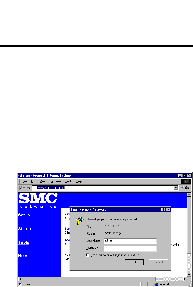
To access the Barricade’s management interface, enter the IP
address of the Barricade in your Web browser, http://192.168.2.1
Then enter the the User Name “admin” with no password. The
home page displays the Main Menu on the left-hand side of the
screen and descriptive information on the right-hand side. The
Main Menu links are used to navigate to other menus that display
configuration parameters and statistics.

N
AVIGATING
THE
W
EB
B
ROWSER
I
NTERFACE
4-2
Navigating the Web Browser Interface
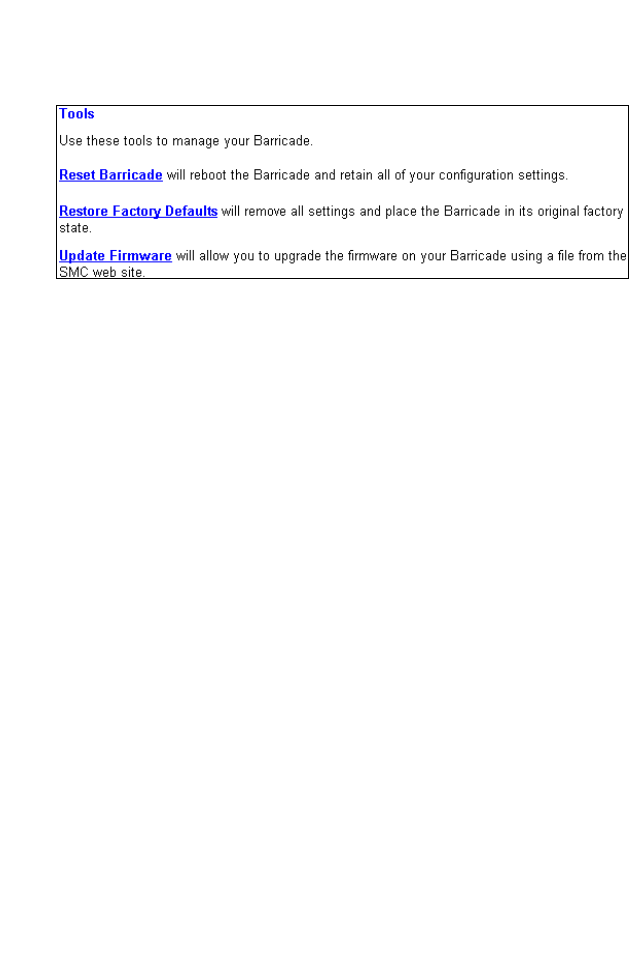
The Barricade’s management interface includes four key menus –
Status, Help, Tools, and Setup. The Status and Help menus provide
general information on the current settings and how to configure
the Barricade. The Setup menu is used to configure the LAN, WAN
and wireless interface, as well as other advanced functions. While
the Tools menu is used to reset the Barricade, restore the factory
settings, or upgrade on-board firmware.
Setting a Password
If this is your first time to access the Barricade, you should define a
new Administrator password, record it and put it in a safe place.
From the Main Menu, select “Setup” and enter the default
password for the Administrator (i.e., “admin”). Then select
“Change Password” and follow the instructions on the screen (see
page 4-6). Note that passwords can consist of 3 to 12 alphanumeric
characters and are not case sensitive.
Making Configuration Changes
Configurable parameters have a dialog box or a drop-down list.
Once a configuration change has been made on a page, be sure to
click on the “Enter” button at the bottom of the page to confirm
the new setting.
Note: To ensure proper screen refresh after a command entry, be
sure that Internet Explorer 5.0 is configured as follows:
Under the menu “Tools / Internet Options / General /
Temporary Internet Files / Settings,” the setting for “Check
for newer versions of stored pages” should be “Every visit
to the page.”

C
ONFIGURING
THE
B
ARRICADE
4-3
Main Menu
Using the management interface, you can define system
parameters, manage and control the Barricade and its ports, or
monitor network conditions. The following table briefly describes
the selections available from this program.
Menu Description
Setup Menu Configures TCP/IP settings and client services.
Change Password Sets the password for administrator access.
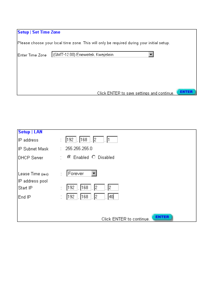
Set Time Zone Sets the local time zone.
LAN Sets the TCP/IP configuration for the
Barricade LAN interface and all DHCP clients.
WAN Specifies the Internet connection type: (1)
DHCP host configuration, (2) fixed IP and
gateway address, (3) PPPoE configuration, or
(4) dial-up modem.
DNS Specifies DNS servers to use for domain name
resolution.
Wireless Configures the radio frequency, domain, and
encryption for wireless communications.
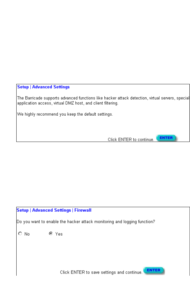
Advanced Settings Configures a variety of packet filtering and
specialized functions, including:
Firewall
NAT
Virtual Server
Special Application
Virtual DMZ Host
Remote Management
Client Filtering

M
AIN
M
ENU
4-4
Status Menu Displays connection status, key interface
settings, as well as the firmware and hardware
version numbers.
INTERNET Displays WAN connection type and status.
GATEWAY Displays system IP settings, the status for
DHCP, NAT and Firewall services, as well as
the wireless interface settings.
INFORMATION Displays the number of attached clients, the
firmware versions, the physical MAC address
for each media interface, as well as the
hardware version and serial number.
Security Log Displays any illegal attempts to access your
network.
DHCP Client Log Displays information on all DHCP clients
attached to your network.
Tools Menu Contains options to reset the system, restore
configuration settings, or update system
firmware.
Reset Barricade Reboots the system and retains all of your
configuration settings.
Restore Factory Defaults Restores all configuration settings to the
factory defaults
Update Firmware Upgrades the system with firmware obtained
from your distributor’s Web support site.
Help Menu Contains information for product support,
troubleshooting, and network terminology.
Menu Description
C
ONFIGURING
THE
B
ARRICADE
4-5
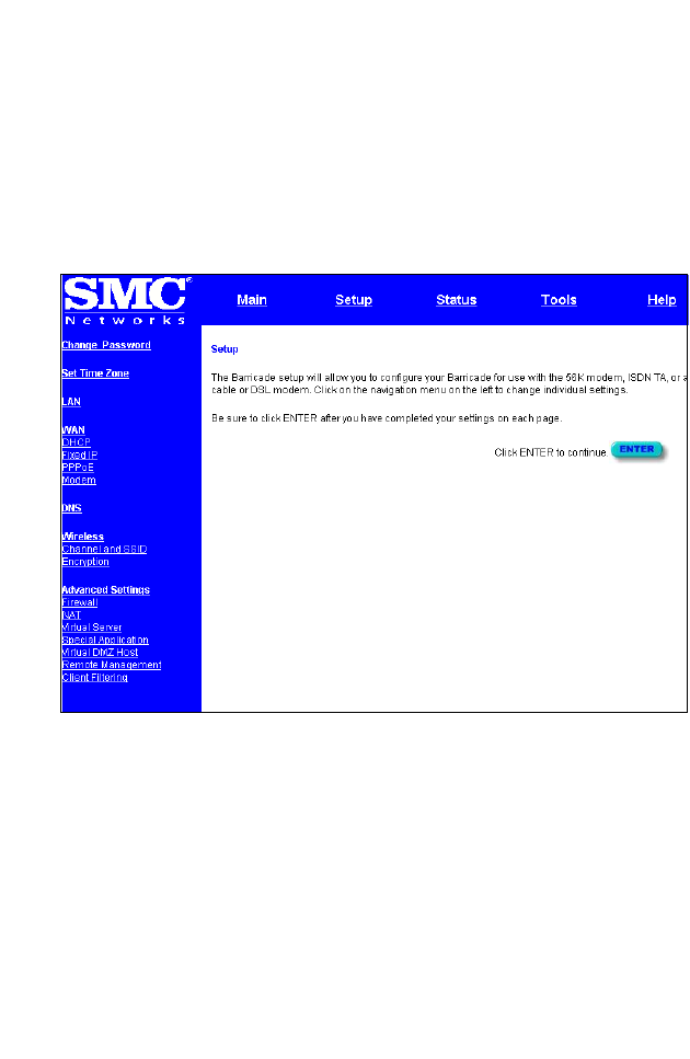
Networking and Client Services
Use the Setup menu to configure the LAN interface (including
TCP/IP parameters for the Barricade’s gateway address, DHCP
address pool for dynamic client address allocation), the WAN
connection options, DNS domain name mapping, the wireless
interface, and other advanced services.
You can use the Setup Wizard by clicking the “Enter” button at the
bottom of the page and changing the required settings, or you can
select the specific items you need to change from the Setup menu
on the left side of the screen.
N
ETWORKING
AND
C
LIENT
S
ERVICES
4-6
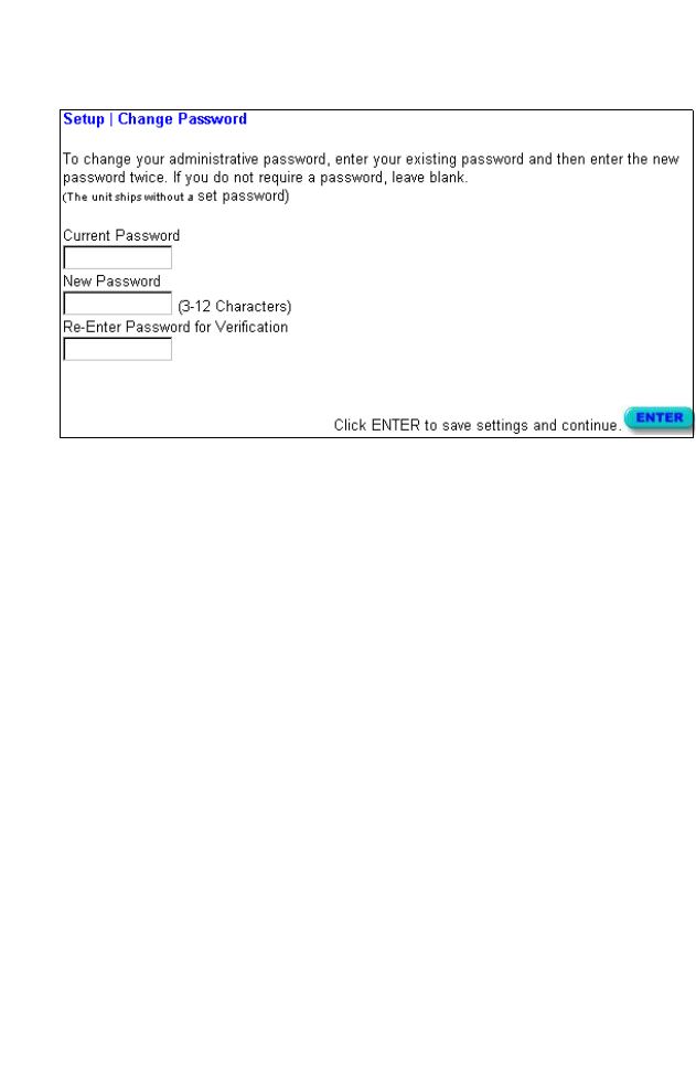
Change Password
Use this menu to restrict management access based on a specific
password. Anyone can access the Status and Help menus, but you
must enter the user name “Admin” and a password to access the
configuration options provided by the Setup and Tools menus.
The default password is null, so please assign a password to the
Administrator as soon as possible, and store it in a safe place.
Passwords can contain from 3–12 alphanumeric characters, and are
not case sensitive.
Note: If your password is lost, or you cannot gain access to the
management interface, press the Reset button on the front
panel (holding it down for at least five seconds).
C
ONFIGURING
THE
B
ARRICADE
4-7
Set Time Zone
Set the time zone for the Barricade. This time is used for log entries
and client filtering.
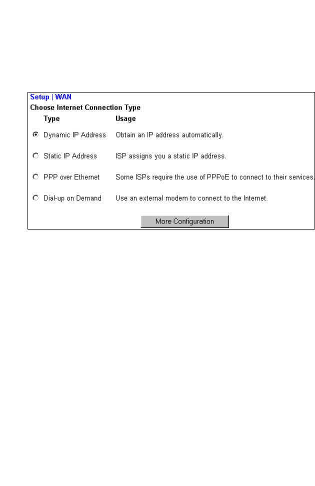
LAN Gateway and DHCP Settings
Configure the gateway address of the Barricade. To dynamically
assign the IP address for client PCs, enable the DHCP Server, set
the lease time, and then specify the address range. Also remember
to configure all of your client PCs for dynamic address allocation.
Valid IP addresses consist of four numbers, and are separated by
periods. The first three fields are the network portion, and can be
from 0–255, while the last field is the host portion and can be from
1–254. However, remember not to include the gateway address of
the Barricade in the client address pool.
N
ETWORKING
AND
C
LIENT
S
ERVICES
4-8
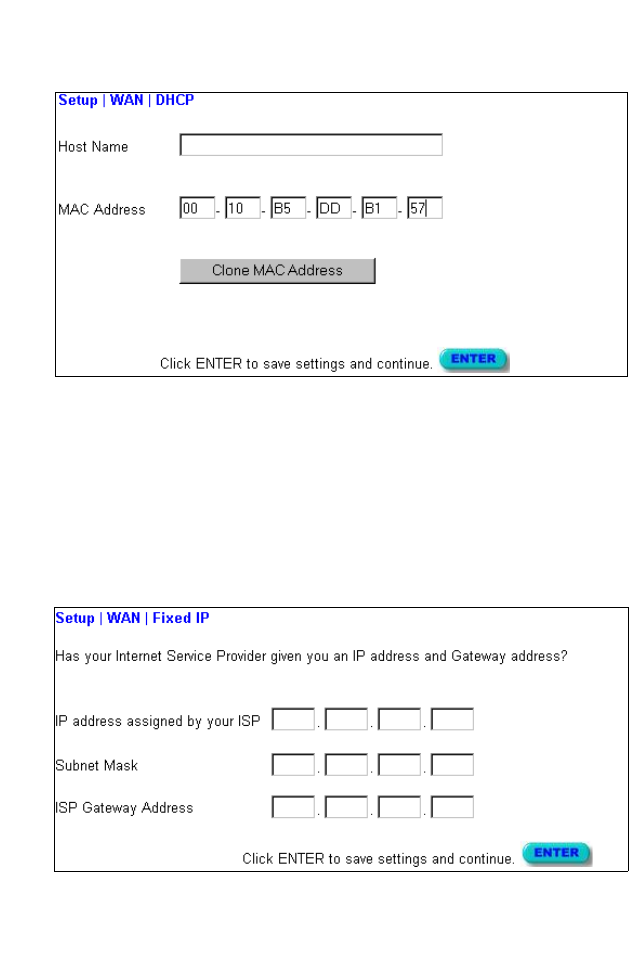
WAN Configuration
Specify the WAN connection type required by your Internet
Service Provider, then click “More Configuration” to provide
detailed configuration parameters for the selected connection type.
Specify one of the first three options to configure a WAN
connection through the RJ-45 port (i.e., a connection to a DSL
modem or Cable modem). Specify the “Dial-up on Demand”
option to configure a WAN connection through the serial port (i.e.,
a connection to an ISDN TA or PSTN modem).
Note: If WAN connections are configured for both the RJ-45 and
serial port, the serial port will be used as a backup Internet
connection if the primary RJ-45 WAN connection fails.
C
ONFIGURING
THE
B
ARRICADE
4-9
Dynamic IP Address – DHCP
The Host Name is optional, but may be required by some ISPs.
The default MAC address is set to the WAN’s
physical interface on
the Barricade. Use this address when registering
for Internet service,
and do not change it unless required by your ISP. You can use the
“Clone MAC Address” button to copy the MAC address of the
Ethernet Card installed by your ISP (in your PC) and replace the
WAN MAC address with this MAC address.
Static IP Address – Fixed IP
If your Internet Service Provider has assigned a fixed address,
enter the assigned address and subnet mask for the Barricade, then
enter the gateway address of your ISP.
N
ETWORKING
AND
C
LIENT
S
ERVICES
4-10
Note: You may need a fixed address if you want to provide
Internet services, such as a Web server or FTP.
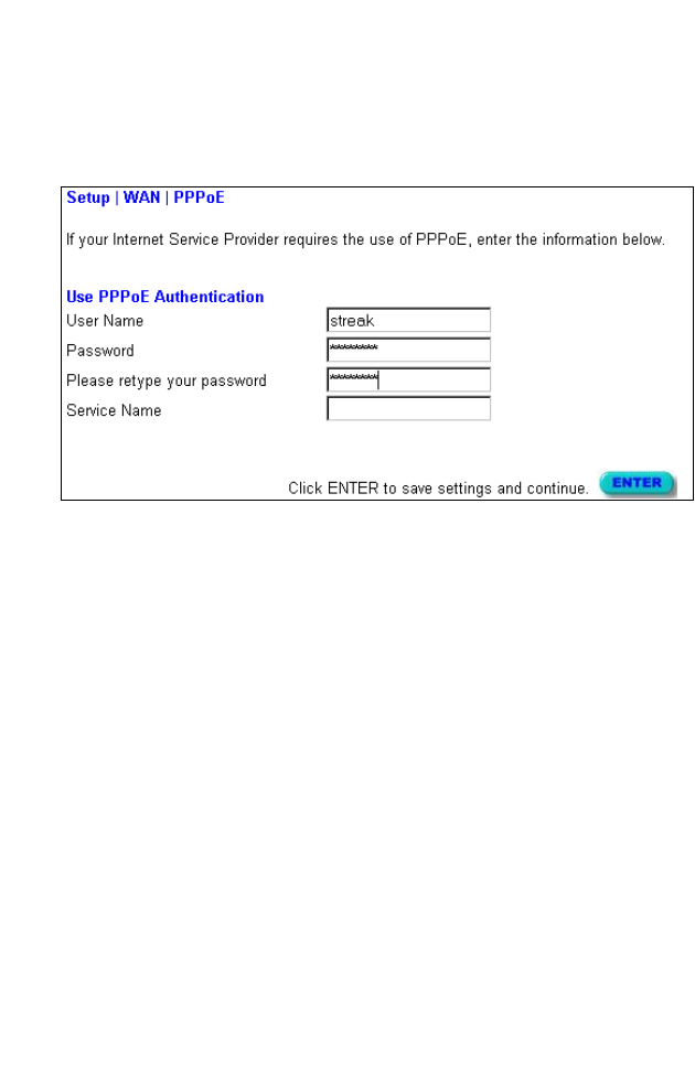
PPP over Ethernet – PPPoE
Enter the PPPoE user name and password assigned by your ISP.
The Service Name is normally optional, but may be required by
some providers.
C
ONFIGURING
THE
B
ARRICADE
4-11
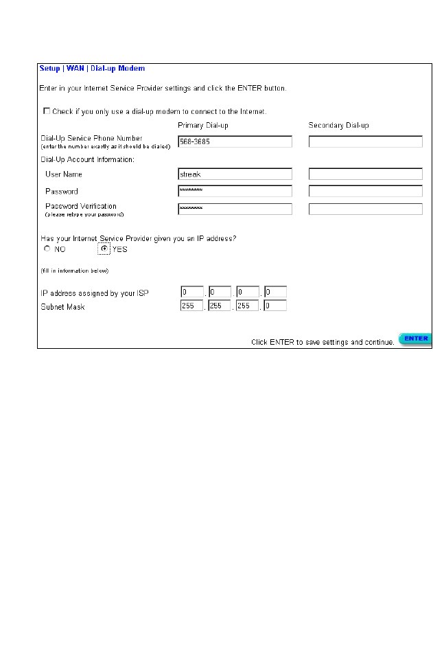
Dial-up on Demand – Modem
If you are accessing the Internet via an ISDN TA or PSTN modem
attached to the serial port on the Barricade, then you must specify
your account information on this screen as described below.
Check if you only use a dial-up modem to connect to the Internet. –
If the serial port is used for primary Internet access, then mark this
item. If not marked, then this connection will only be used for
backup access if the primary WAN link fails.
Dial-Up Service Phone Number – Enter the phone number your
service provider has given to you for Internet access.
Dial-Up Account Information – Enter your ISP account user name
and password.
Has your Internet Service Provider given you an IP address? –
If you are assigned a dynamic IP address every time you dial up,
mark “No” for this item. However, if your ISP has assigned a fixed
IP address for you to use, mark “Yes” for this item and enter the IP
N
ETWORKING
AND
C
LIENT
S
ERVICES
4-12
address and subnet mask.
Note: If your ISP has given you a secondary phone number, or if
you have a secondary Internet service account, then fill in
the relevant fields under “Secondary Dial-up.”
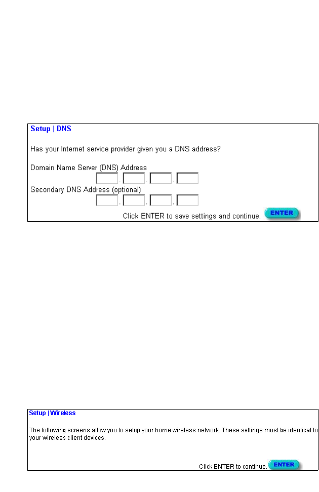
DNS Configuration
Domain Name Servers are used to map an IP address to the
equivalent domain name (e.g., www.smc.com). Your ISP should
provide the IP address for one or more domain name servers.
Enter those addresses on this screen.
Wireless Configuration
To configure the Barricade as a wireless access point for wireless
clients (either stationary or roaming), all you need to do is define
the radio channel, the domain identifier, and encryption options.
You can use the Setup Wizard by clicking the “Enter” button at the
bottom of the page and changing the required settings, or you can
select “Channel and SSID” or “Encryption” from the Setup menu
on the left side of the screen.
C
ONFIGURING
THE
B
ARRICADE
4-13
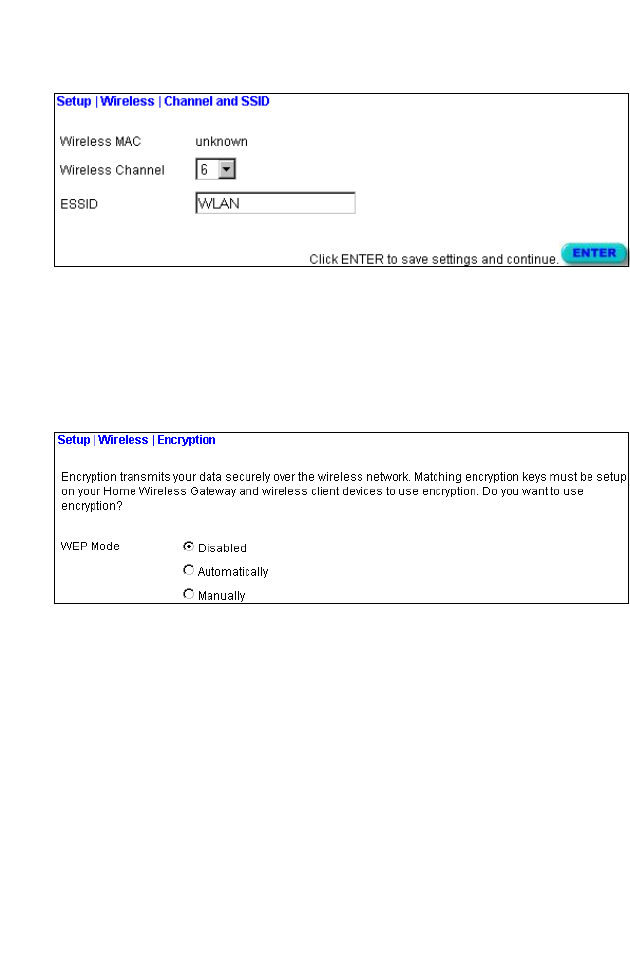
Channel and SSID
You must specify a common radio channel and service domain
(i.e., Extended Service Set ID) to be used by the Barricade and all
of your wireless clients. Be sure you configure all of your clients to
the same values.
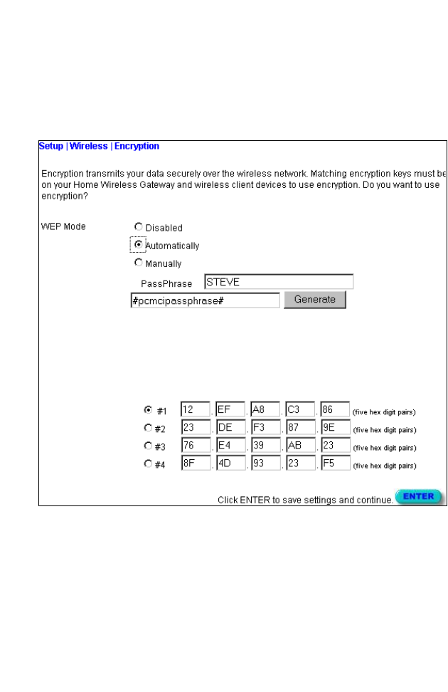
Encryption
If you are transmitting sensitive data across wireless channels, you
should enable encryption. Encryption requires you to use the same
set of encryption/decryption keys for the Barricade and all of your
wireless clients. However, note that the extra processing time
required for encryption may affect the throughput for wireless
communications, and therefore should not be used unless actually
necessary.
N
ETWORKING
AND
C
LIENT
S
ERVICES
4-14
You can automatically generate encryption keys by entering a pass
phrase that will be used to create four keys as shown below, or
you can manually enter the keys. To manually configure the keys,
enter five hexadecimal pairs for each key. (A hexadecimal digit is a
number or letter in the range 0-9 or A-F.)
If you use encryption, then configure the same keys used for the
Barricade on each of your wireless clients. Note that the Wireless
Encryption Protocol (WEP) protects data transmitted between
wireless nodes, but does not protect any transmissions over your
wired network or over the Internet.
C
ONFIGURING
THE
B
ARRICADE
4-15
Configuring Client Services
The Barricade includes a broad range of client services, including
firewall protection, network address translation / virtual server,
connection support for special applications, and restricted Internet
access for specified clients. You can configure these functions
using the Setup Wizard by clicking “Enter” at the bottom of the
Advanced Settings screen, or by selecting specific items from the
menu at the left of the screen.
Firewall Protection
The Barricade’s firewall can block common hacker attacks,
including IP Spoofing, Land Attack, Ping of Death, IP with zero
length, Smurf Attack, UDP port loopback, Snork Attack, TCP null
scan, and TCP SYN flooding. The firewall does not significantly
affect system performance, so we advise leaving it enabled to
protect your network users.
N
ETWORKING
AND
C
LIENT
S
ERVICES
4-16
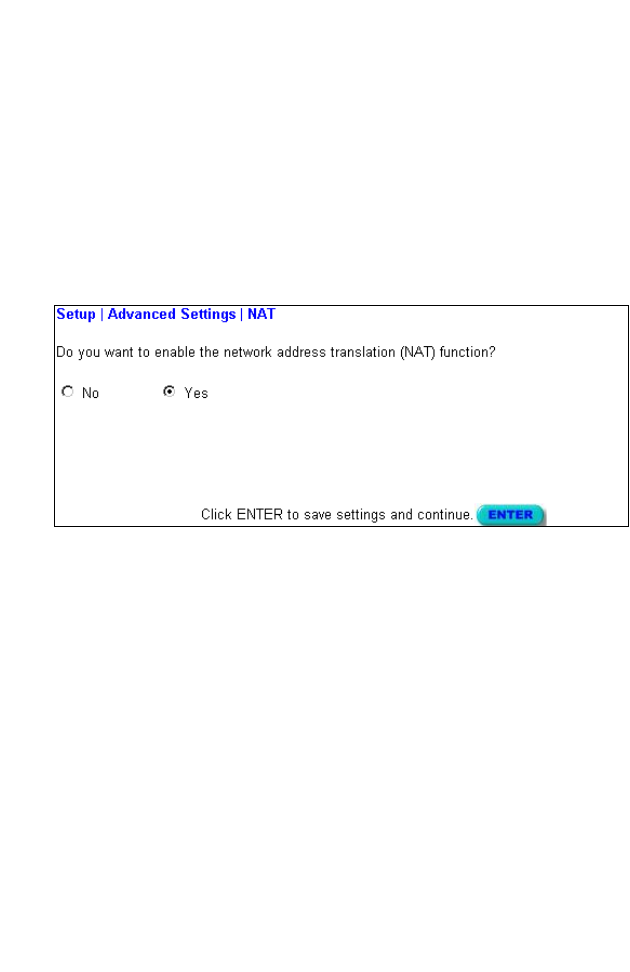
Network Address Translation – NAT
Network Address Translation can be used to give multiple users
access to the Internet with a single user account, or to map the
local address for an IP server (such as Web or FTP) to a public
address. This secures your network from direct attack by hackers,
and provides more flexible management by allowing you to
change internal IP addresses without affecting outside access to
your network. Note that NAT must be enabled to provide multi-
user access to the Internet or to use the Virtual Server function.
C
ONFIGURING
THE
B
ARRICADE
4-17
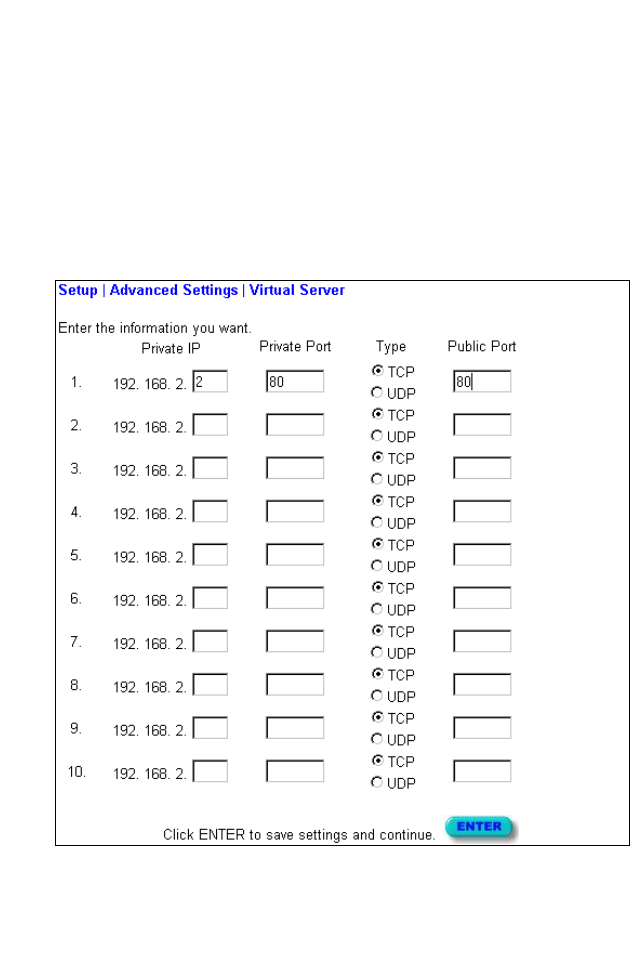
Virtual Server
If you configure the Barricade as a virtual server, remote users
accessing services such as Web or FTP at your local site via public
IP addresses can be automatically redirected to local servers
configured with private IP addresses. In other words, depending
on the requested service (TCP/UDP port number), the Barricade
redirects the external service request to the appropriate server
(located at another internal IP address).
You must have a fixed IP to utilize this function. For example, if
you set Type/Public Port to TCP/80 (HTTP or Web) and the Private
IP/Port to 192.168.2.2/80, then all HTTP request from outside users
N
ETWORKING
AND
C
LIENT
S
ERVICES
4-18
will be transferred to 192.168.2.2. Therefore, by just entering the IP
Address provided by the ISP, Internet users can access the service
they need at the local address to which you redirect them.
Some of the more common TCP service ports include:
HTTP: 80, FTP: 21, Telnet: 23 and POP3: 110.
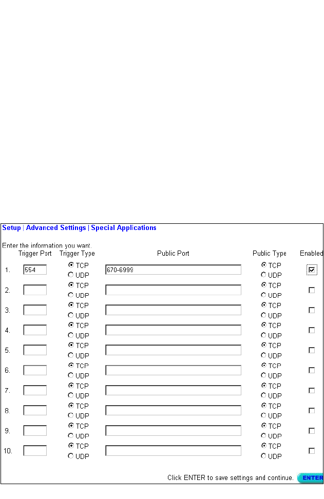
Enabling Special Applications
Some applications require multiple connections, such as Internet
games, videoconferencing, Internet telephony and others. These
applications may not work when Network Address Translation
(NAT) is enabled. If you need to run applications that require
multiple connections, use the following screen to specify the
additional public ports to be opened for each application.
C
ONFIGURING
THE
B
ARRICADE
4-19
Specify the port normally associated with an application in the
“Trigger Port” field, select the protocol type as TCP or UDP, then
enter the public ports associated with the trigger port to open
them for inbound traffic.
Note: If an application still cannot function correctly after
enabling multiple ports via the Special Application screen,
you may have to open the client PC for full Internet access
using the DMZ Host option.
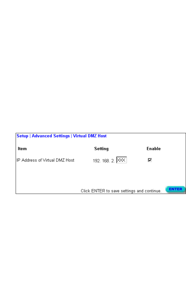
Virtual DMZ Host
If you have a client PC that cannot run an Internet application
properly from behind the NAT firewall or after configuring the
Special Applications function, then you can open the client up to
unrestricted two-way Internet access.
Enter the IP address of a DMZ host to this screen. Adding a client
to the DMZ (Demilitarized Zone) may expose your local network
to a variety of security risks, so only use this option as a last resort.
N
ETWORKING
AND
C
LIENT
S
ERVICES
4-20
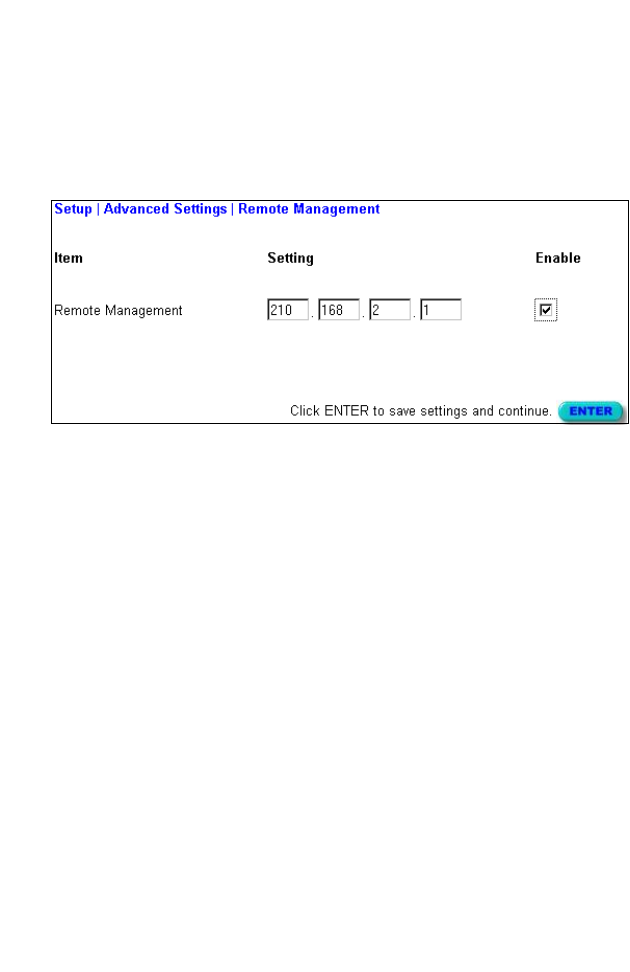
Remote Management
By default, management access is only available to users on your
local network. However, you can also manage the Barricade from
a remote host by adding the IP address of an administrator to this
screen.
Note: If you specify an IP address of 0.0.0.0, any host can manage
the Barricade.
C
ONFIGURING
THE
B
ARRICADE
4-21
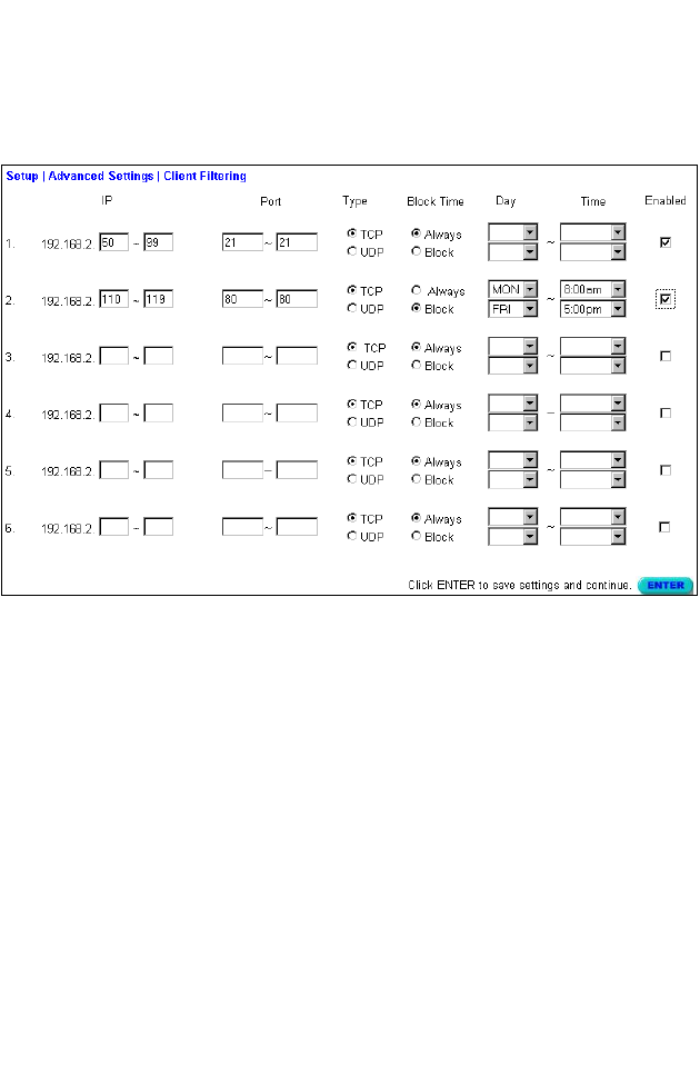
Client Filtering
You can filter Internet access for local clients based on IP address,
application type (i.e., HTTP port), and time of day.
For example, this screen shows that clients in the address range
192.168.2.50-99 are permanently restricted from using FTP (Port
21), while clients in the address range 192.168.2.110-119 are
blocked from browsing the Internet from Monday through Friday.
V
IEWING
N
ETWORK
AND
D
EVICE
S
TATUS
4-22
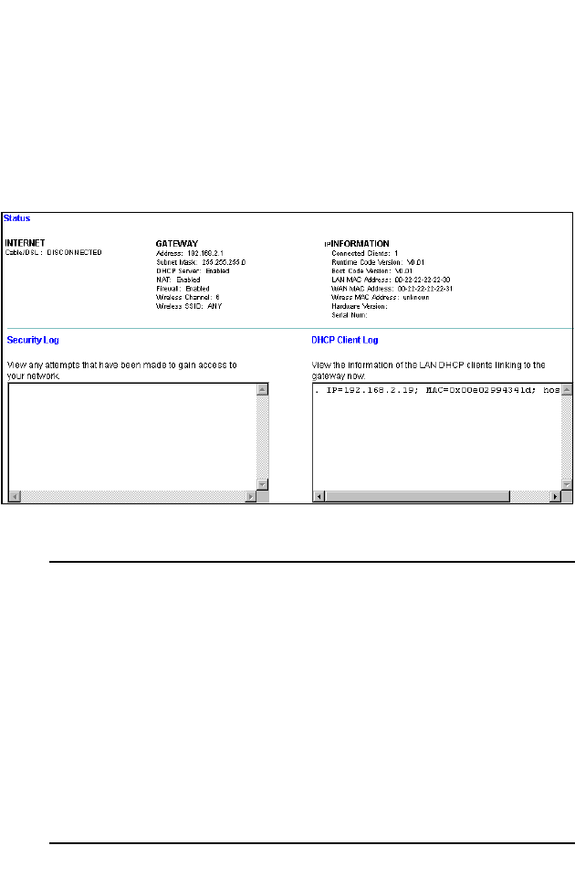
Viewing Network and Device Status
You can use the following screen to display the connection status for
the WAN/WLAN/LAN interfaces, firmware and hardware version
numbers, any illegal attempts to access your network, as well as
information on all DHCP clients connected to your network.
The following items are included in this screen:
Field Description
INTERNET Displays WAN connection type and status.
GATEWAY Displays system IP settings, the status for
DHCP, NAT and Firewall services, as well as
the wireless interface settings.
INFORMATION Displays the number of attached clients, the
firmware versions, the physical MAC address
for each media interface, as well as the
hardware version and serial number.
Security Log Displays any illegal attempts to access your
network.
DHCP Client Log Displays information on all DHCP clients on
your network.
C
ONFIGURING
THE
B
ARRICADE
4-23
Using System Tools
You can use the “Tools” menu to reboot the Barricade, restore
factory settings, or update firmware.
Note: If you use the Reset button on the front panel, the
Barricade performs a power reset and restores the factory
settings.

U
SING
S
YSTEM
T
OOLS
4-24
5-1
C
HAPTER
5
C
ONFIGURING
C
LIENT
TCP/IP
If you have previously installed the TCP/IP protocol on your client
PCs, refer to the following section. If you need information on
how to configure a TCP/IP address on a PC, refer to “Setting TCP/
IP to Work with the Barricade” on page 5-3.
Installing TCP/IP Protocol in Your PC
1. Click the Start button and choose Settings, then click Control
Panel.
2. Double click the Network icon and select the Configuration tab
in the Network window.
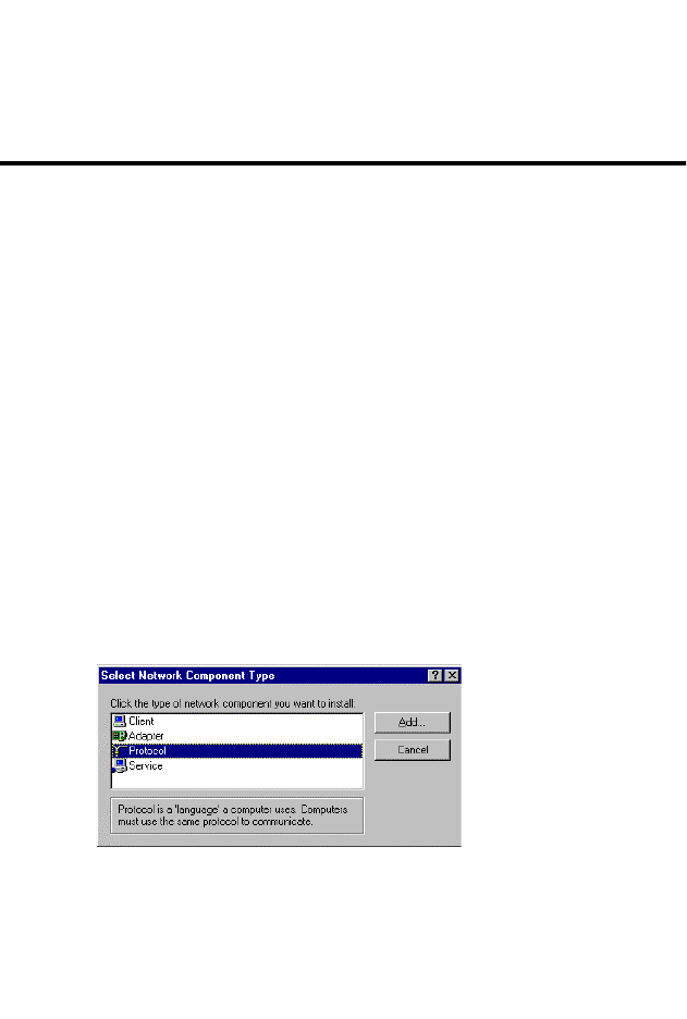
3. Click the
Add
button to add the network component to your PC.
4. Double click Protocol to add the TCP/IP protocol.
I
NSTALLING
TCP/IP P
ROTOCOL
IN
Y
OUR
PC
5-2
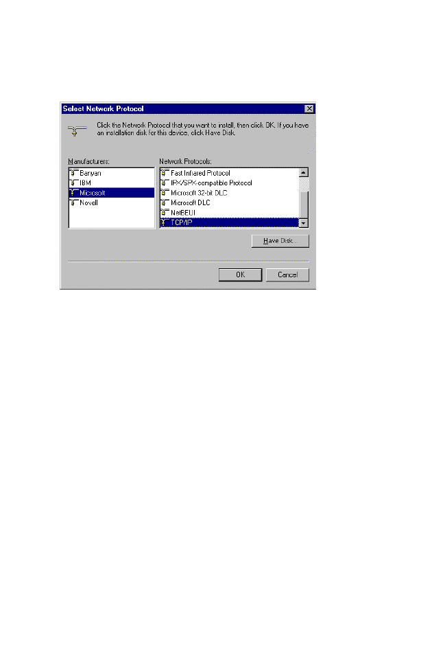
5. Select the Microsoft item in the manufacturers list. And choose
TCP/IP in the Network Protocols. Click the OK button to return
to the Network window.
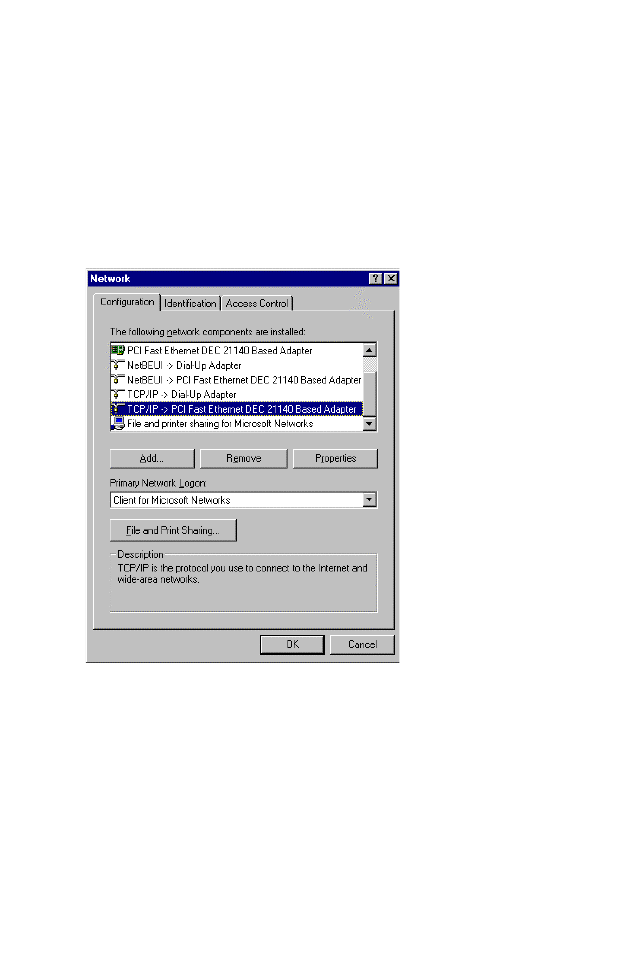
6. The TCP/IP protocol will be listed in the Network window.
Click OK to complete the install procedure and restart your PC
to enable the TCP/IP protocol.
C
ONFIGURING
C
LIENT
TCP/IP
5-3
Setting TCP/IP to Work with the Barricade
1. Click the Start button and choose Settings, then click Control
Panel.
2. Double click the Network icon. Select the TCP/IP line that has
been assigned to your network card in the Configuration tab
of the Network window.
3. Click the Properties button to set the TCP/IP protocol for the
Barricade.
4. You can dynamically assign TCP/IP address settings to a client,
or you can manually configure a client with address settings to
meet your specific network requirements. (Note that the
default IP address of the Barricade is 192.168.2.1.)
S
ETTING
TCP/IP
TO
W
ORK
WITH
THE
B
ARRICADE
5-4
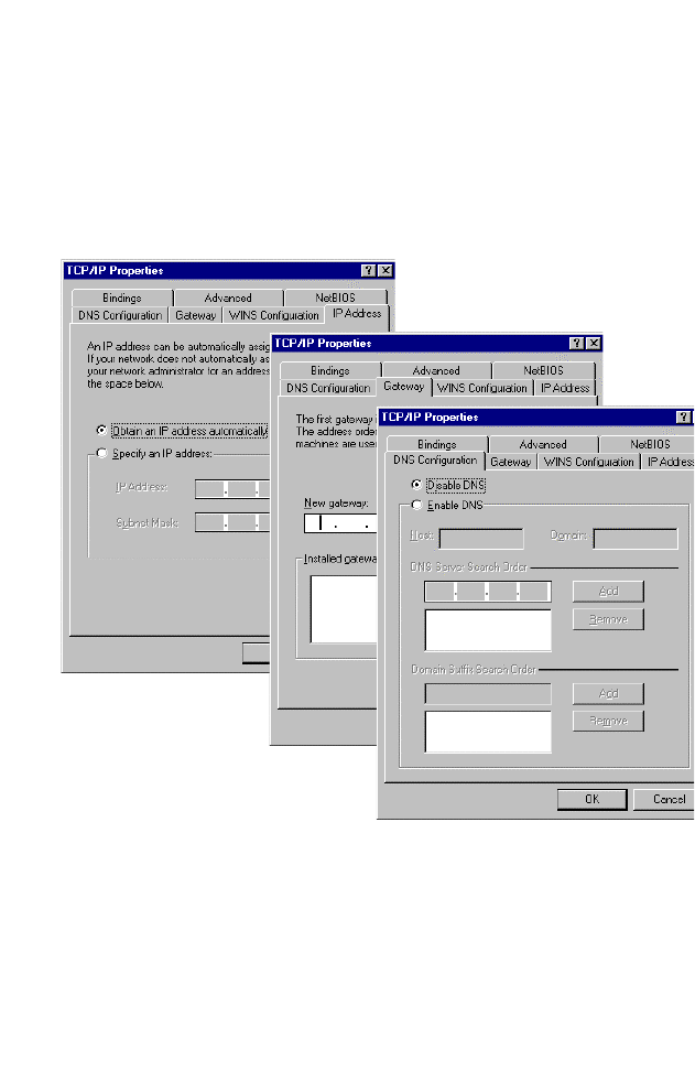
Dynamic IP Allocation via a DHCP Server
Select Obtain an IP address automatically in the IP Address tab.
Do not input any values under the Gateway tab, and choose
Disable DNS in the DNS Configuration tab. These settings will be
automatically configured by the DHCP server. Click OK and reboot
your system to implement the changes.
C
ONFIGURING
C
LIENT
TCP/IP
5-5
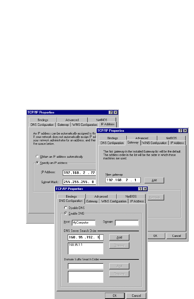
Manual IP Configuration
1. Select Specify an IP address in the IP Address tab. Select an IP
address based on the default network 192.168.2.X (where X is
between 1 and 253), and use 255.255.255.0 for the subnet mask.
2. In the Gateway tab, add the IP address of the Barricade
(default: 192.168.2.1) in the New gateway field and click Add.
3.
In the
DNS Configuration
tab, add the IP address for the Barricade
and click Add. This automatically relays DNS requests to the
DNS server(s) provided by your ISP. Otherwise, add specific
DNS servers into the
DNS Server Search Order
field and click
Add
.

S
ETTING
TCP/IP
TO
W
ORK
WITH
THE
B
ARRICADE
5-6
4. After finishing TCP/IP setup, click OK, and then reboot the
computer. After that, set up other PCs on the LAN according to
the procedures described above.
Verifying Your TCP/IP Connection
After installing the TCP/IP communication protocol and
configuring an IP address in the same network with the Barricade,
you can use the ping command to check if your computer is
successfully connected to the Barricade. The following example
shows how the ping procedure can be executed in an MS-DOS
window. First, execute the ping command:
ping 192.168.2.1
If the following messages appear:
Pinging 192.168.2.1 with 32 bytes of data:
Reply from 192.168.2.1: bytes=32 time=2ms TTL=64
a communication link between your computer and the Barricade
has been successfully established. Otherwise, if you get the
following messages,
Pinging 192.168.2.1 with 32 bytes of data:
Request timed out.
there may be something wrong in your installation procedure.
Check the following items in sequence:
1. Is the Ethernet cable correctly connected between the
Barricade and your computer?
The LAN LED on the Barricade and the Link LED of the
network card on your computer must be on.
2. Is TCP/IP properly configured on your computer?
If the IP address of the Barricade is 192.168.2.1, the IP address
of your PC must be from 192.168.2.2 - 192.168.2.254 and the
default gateway must be 192.168.2.1.

C
ONFIGURING
C
LIENT
TCP/IP
5-7
If you can successfully ping the Barricade, then you are now ready
to connect to the Internet!

S
ETTING
TCP/IP
TO
W
ORK
WITH
THE
B
ARRICADE
5-8

6-1
C
HAPTER
6
C
ONFIGURING
P
RINTER
S
ERVICES
If you want to use the print server built into the Barricade, then
you must first install the Port Monitor program as described in the
following section for Windows 95/98/NT.
To configure the Barricade Print Server for Windows 95/98/ME/
NT/2000 or Unix, see “Configure the Print Server” on page 6-4.
Install the Printer Port Monitor
Skip this section if you do not want to use the Barricade print server
or if you are using Windows ME/2000 or Unix.
For Windows 95/98/NT clients, you need to install the port
monitor program as described in this section.
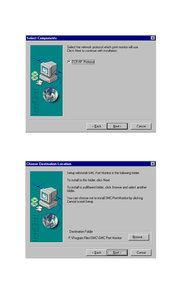
1. Insert the installation CD-ROM into your CD-ROM drive. Under
the PrintSvr directory, run the “setup.exe” program. The SMC
Port Monitor installation program advises you to close all other
Windows programs currently running on your computer. Click
Next to continue.
I
NSTALL
THE
P
RINTER
P
ORT
M
ONITOR
6-2
2. The next screen indicates that the print client uses TCP/IP
network protocol to monitor print requests. Click Next.
3. Select the destination folder and click on the Next button. The
setup program will then begin to install the programs into the
destination folder.
C
ONFIGURING
P
RINTER
S
ERVICES
6-3
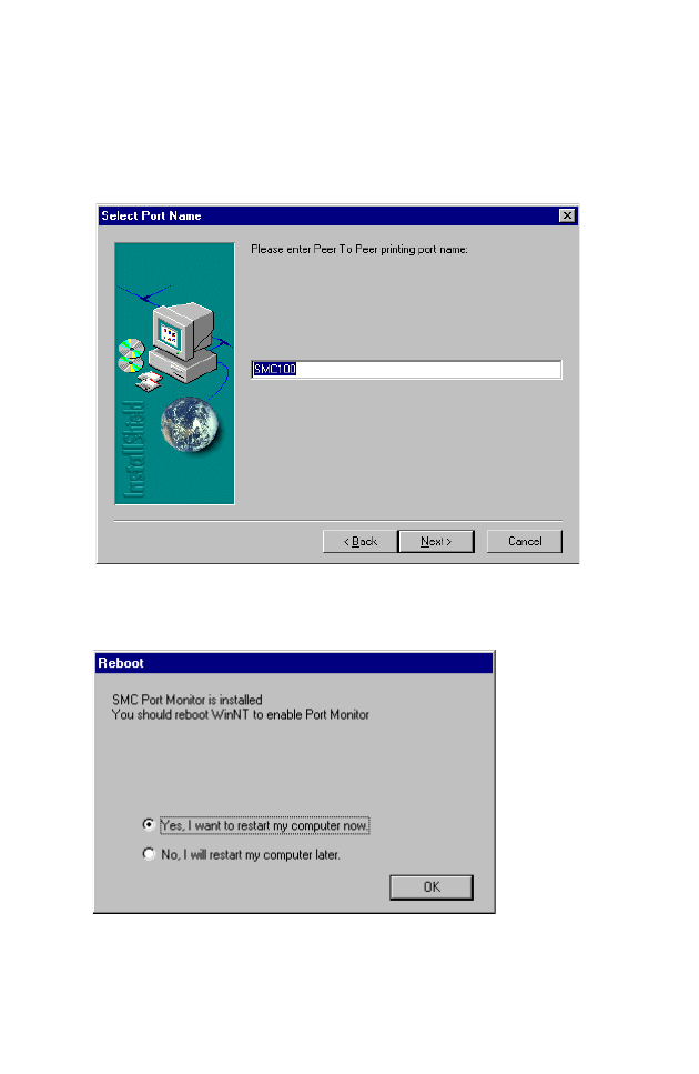
4. Select the Program Folder that will contain the program icon
for uninstalling the port monitor, and then click Next.
5. Enter the printer port name that will be used to identify the
port monitor in your system, and press Next.
6. When the setup program finishes installing the port monitor,
select the item to restart the computer and then click OK.
7. After rebooting your computer, add the Barricade print server
to your system as described in the following section.
C
ONFIGURE
THE
P
RINT
S
ERVER
6-4
Configure the Print Server
After you install the port monitor as described in the previous
section, add the Barricade’s print server to your operating system.
The Barricade’s print server supports MS Windows 95/98/ME/NT/
2000 and Unix based platforms.
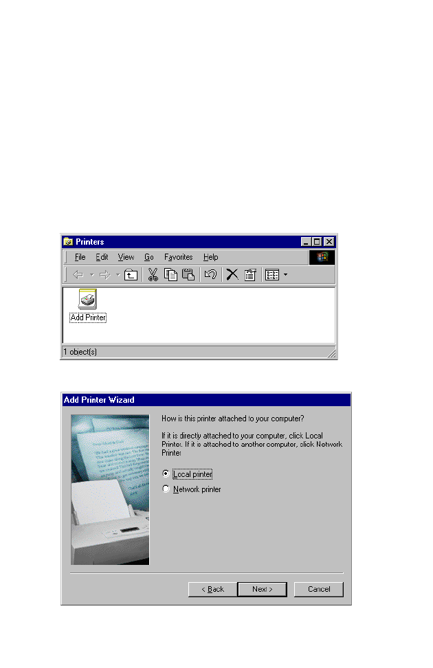
Configure the Network Printer in Windows 95/98
1. On a Windows 95/98 platform, open the Printers window in
the
My Computer
menu, and double-click the
Add Printer
icon.
2. Follow the prompts to add a Local printer to your system.
3. Specify the printer type attached to the Barricade.
C
ONFIGURING
P
RINTER
S
ERVICES
6-5
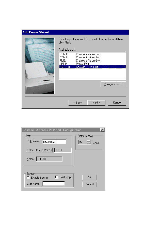
4. Select the monitored port. The default port name is “SMC100”
and then click the Configure Port button.
5. Enter the IP address of the Barricade and click OK, and then
click Next in the Add Printer Wizard dialog box.
6. Continue following the prompts to finish installing the
Barricade print server. The printer type you specified will now
be added to your Printers menu.
C
ONFIGURE
THE
P
RINT
S
ERVER
6-6
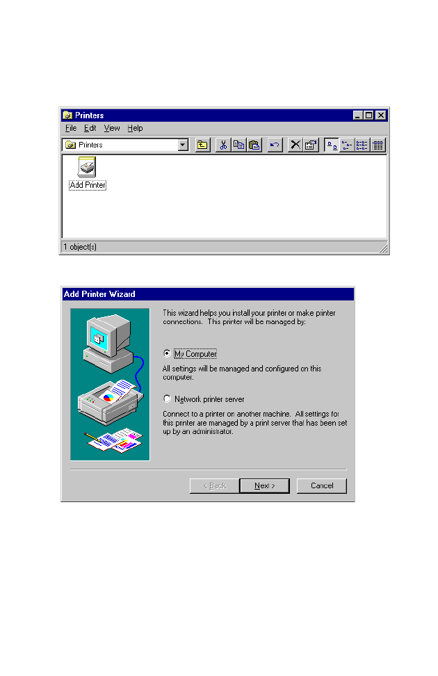
Configure the Network Printer in Windows NT
1. On a Windows NT platform, open the Printers window in
the
My Computer menu, and double-click the
Add Printer
icon.
2. Follow the prompts to add a local printer to your system.
C
ONFIGURING
P
RINTER
S
ERVICES
6-7
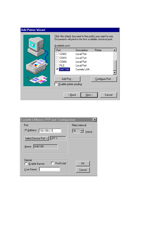
3. Select the monitored port. The default port name is “SMC100.”
Then click the Configure Port button.
4. Enter the IP address of the Barricade and click OK, and then
click Next in the Add Printer Wizard dialog box.
5. Specify the printer type attached to the Barricade.
6. Continue following the prompts to finish installing the
Barricade print server. The printer type you specified will now
be added to your Printers menu.
C
ONFIGURE
THE
P
RINT
S
ERVER
6-8
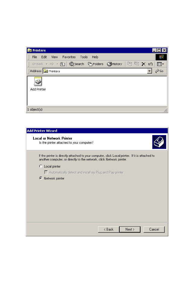
Configure the Network Printer in Windows 2000
1. On a Windows 2000 platform, open the Printers window in
the
My Computer menu, and double-click the
Add Printer
icon.
2. Select Network printer and click Next.
C
ONFIGURING
P
RINTER
S
ERVICES
6-9
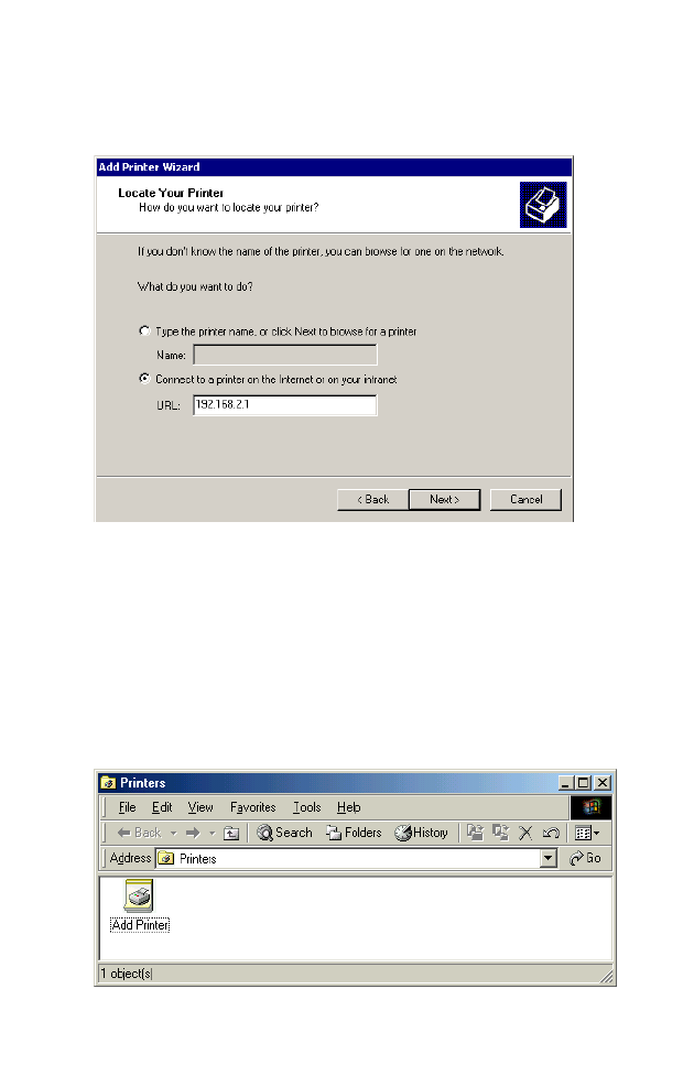
3. Select the option Connect to a printer on the Internet or on
your intranet, enter the IP address of the Barricade in the URL
field, and then click Next.
4. Specify the printer type attached to the Barricade.
5. Continue following the prompts to finish installing the printer.
The specified printer type will be added to your Printers menu.
Configure the Network Printer in Windows ME
1. On a Windows ME platform, open the Printers window in
the
My Computer menu, and double-click the
Add Printer
icon.

C
ONFIGURE
THE
P
RINT
S
ERVER
6-10
2. Select Network printer and click Next.
3. Enter the IP address of the Barricade, and click Next.
4. Specify the printer type attached to the Barricade.
5. Continue following the prompts to finish installing the printer.
The specified printer type will be added to your Printers menu.

C
ONFIGURING
P
RINTER
S
ERVICES
6-11
Configure the Network Printer in Unix Systems
Follow the traditional configuration procedure on Unix platforms
to set up the Barricade print server. The printer name is “lp.”

C
ONFIGURE
THE
P
RINT
S
ERVER
6-12

A-1
A
PPENDIX
A
T
ROUBLESHOOTING
Diagnosing Gateway Indicators
The gateway can be easily monitored through panel indicators to
identify problems. This section describes common problems you
may encounter and possible solutions.
Troubleshooting Chart
Symptom Action
LED Indicators
Power LED is Off •External power supply has failed or is
disconnected.
•Check connections between the Barricade, the
external power supply, and the wall outlet.
•If the power indicator does not turn on when the
power cord is plugged in, you may have a
problem with the power outlet, power cord, or
external power supply.
However, if the unit powers off after running for
a while, check for loose power connections,
power losses or surges at the power outlet.
If you still cannot isolate the problem, then the
external power supply may be defective. In this
case, contact SMC Technical Support for
assistance.

T
ROUBLESHOOTING
A-2
LED Indicators
Link LED is Off •Verify that the Barricade and attached device are
powered on.
•Be sure the cable is plugged into both the
Barricade and the corresponding device.
•Verify that the proper cable type is used and its
length does not exceed specified limits.
•Be sure that the network interface on the
attached device is configured for the proper
communication speed and duplex mode.
•Check the adapter on the attached device and
cable connections for possible defects. Replace
any defective adapter or cable if necessary.
Network Connection Problems
Cannot Ping the
Barricade from the
attached LAN, or the
Barricade cannot Ping
any device on the
attached LAN
•Verify that IP addresses are properly configured.
For most applications, you should use the
Barricade’s DHCP function to dynamically assign
IP addresses to any host on the attached LAN.
However, if you manually configure any IP
addresses on the LAN, verify that the same
network address (network component of the IP
address) and subnet mask are used for both the
Barricade and attached LAN devices.
•Be sure the device you want to ping (or from
which you are pinging) has been configured for
TCP/IP.
Mobile users cannot
access the Barricade
•Make sure that the Barricade and all mobile users
are configured to use the same radio channel,
wireless domain (ESSID), and encryption keys.
•Ensure that all mobile users are within range of
the Barricade as specified in Appendix C.
Troubleshooting Chart
Symptom Action

T
ROUBLESHOOTING
A-3
Management Problems
Cannot connect using
the Web browser
•Be sure to have configured the Barricade with a
valid IP address, subnet mask and default
gateway.
•Check that you have a valid network connection
to the Barricade and that the port you are using
has not been disabled.
•Check network cabling between the
management station and the Barricade.
Forgot or lost the
password
•Press the RESET button on the rear panel to
restore the factory defaults.
Printer Server
The printer cannot print
or prints garbage
•Make sure the parallel cable between the
Barricade and printer is connected and is in good
condition
Troubleshooting Chart
Symptom Action

T
ROUBLESHOOTING
A-4

B-1
A
PPENDIX
B
C
ABLES
Ethernet Cable
Specifications
Straight-through Cable
Caution: DO-NOT plug a phone jack connector into any RJ-45
port. Use only twisted-pair cables with RJ-45 connectors
that conform with FCC standards.
For 10BASE-T/100BASE-TX connections, a twisted-pair cable must
have two pairs of wires. Each wire pair is identified by two
different colors. For example, one wire might be red and the other,
red with white stripes. Also, an RJ-45 connector must be attached
to both ends of the cable. All the RJ-45 ports on the Barricade
support automatic MDI/MDI-X configuration. This means that you
can use straight-through cable to attach to any network device.
The Ethernet cable you use on the Barricade can be wired straight
through for Pins 1, 2, 3 and 6, matching the same pins at the both
ends of the cable. Pins 4, 5, 7 and 8 are not used.
Cable Types and Specifications
Cable Type Max. Length Connector
10BASE-T Cat. 3, 4, 5 100-ohm UTP 100 m (328 ft) RJ-45
100BASE-TX Cat. 5 100-ohm UTP 100 m (328 ft) RJ-45
C
ABLES
B-2
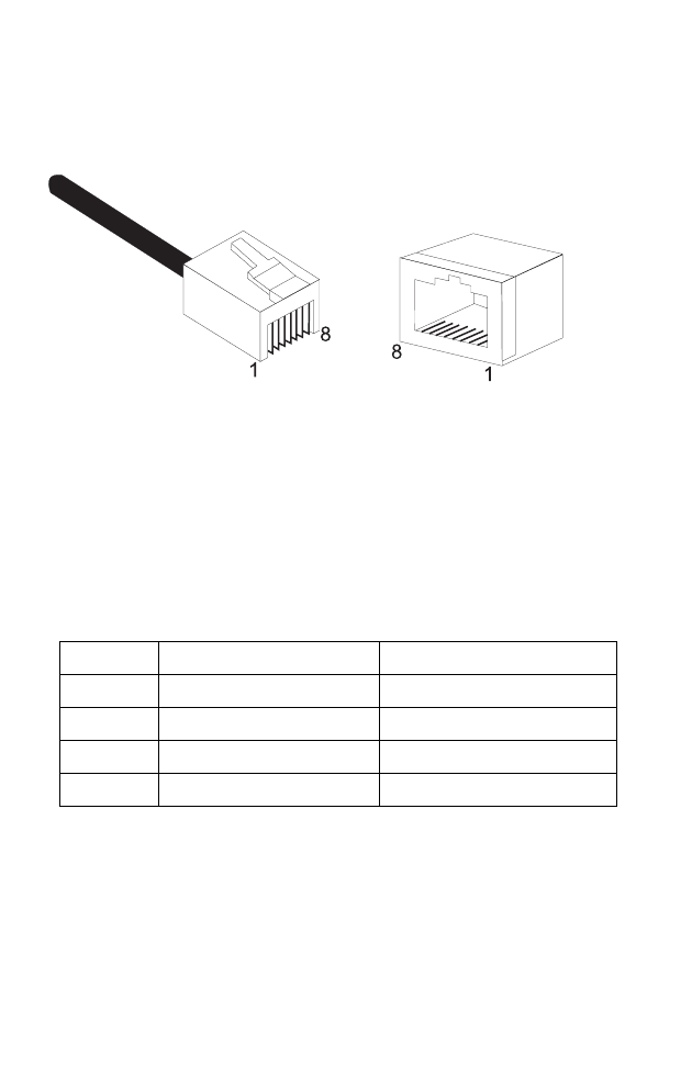
Figure B-1 illustrates how the pins on the RJ-45 connector are
numbered. Be sure to hold the connectors in the same orientation
when attaching the wires to the pins.
Figure B-1. RJ-45 Connector Pin Numbers
RJ-45 Port Pin Assignments
All RJ-45 ports on the Barricade support automatic MDI/MDI-X
configuration. This means that the pin signals in use will depend
on whether the port is operating in MDI or MDI-X mode.
Pin MDI Signal Name* MDI-X Signal Name*
1 Transmit Data (TD+) Receive Data (RD+)
2 Transmit Data (TD-) Receive Data (RD-)
3 Receive Data (RD+) Transmit Data (TD+)
6 Receive Data (RD-) Transmit Data (RD1-)
Pins 4, 5, 7 and 8 are not connected.
* The “+” and “-” signs represent the polarity of the wires that make
up each wire pair.
C
ABLES
B-3
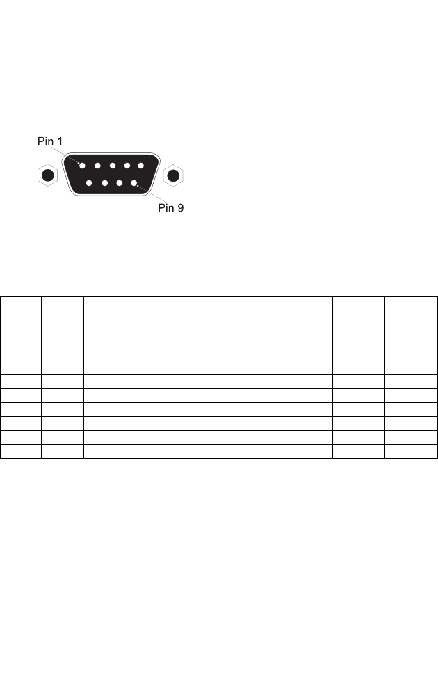
Serial Port Pin Assignments
The DB-9 serial port on the rear panel is used to connect to the
Barricade to an ISDN TA or PSTN modem. The pin assignments
used to connect to this port are provided in the following tables.
Figure B-2. DB-9 Serial Port Pin Numbers
DB-9 Port Pin Assignments
EIA
Circuit
CCITT
Signal
Description Gateway’s
DB9 DTE
Pin #
PC DB9
DTE
Pin #
Modem
DB25
DCE Pin #
Signal
Direction
DTE-DCE
CF 109 DCD (Data Carrier Detected) 1 1 8 <------
BB 104 RxD (Received Data) 2 2 3 <------
BA 103 TxD (Transmitted Data) 3 3 2 ------>
CD 108.2 DTR (Data Terminal Ready) 4 4 20 ------>
AB 102 SG (Signal Ground) 5 5 7 -------
CC 107 DSR (Data Set Ready) 6 6 6 <------
CA 105 RTS (Request-to-Send) 7 7 4 ------>
CB 106 CTS (Clear-to-Send) 8 8 5 <------
CE 125 RI (Ring Indicator) 9 9 22 <------

C
ABLES
B-4
Serial Port to 9-Pin COM Port on PC
Serial Port to 25-Pin DCE Port on Modem
Serial Port to 25-Pin DTE Port on PC
Gateway’s 9-Pin
Serial Port
CCITT Signal PC’s 9-Pin
COM Port
1 DCD ----------- DCD ------------ 1
2 RXD <--------- TXD ------------ 3
3 TXD ----------- RXD ----------> 2
4 DTR ----------- DSR ----------> 6
5 SGND ----------- SGND ---------- 5
6 DSR ----------- DTR ------------ 4
7 RTS ----------- CTS -----------> 8
8 CTS <--------- RTS ------------- 7
9 RI ----------- RI --------------- 9
Gateway’s 9-Pin
Serial Port
CCITT Signal Modem’s 25-Pin
DCE Port
1 <--------- DCD ------------ 8
2 <--------- RXD ------------ 3
3 ----------- TXD ----------> 2
4 ----------- DTR ----------> 20
5 ----------- SGND ---------- 7
6 <--------- DSR ------------ 6
7 ----------- RTS -----------> 4
8 <--------- CTS ------------- 5
9 <--------- RI --------------- 22
Gateway’s 9-Pin
Serial Port
Null Modem PC’s 25-Pin
DTE Port
1 DCD 8 DCD
2 RXD 3 TXD
3 TXD 2 RXD
4 DTR 20 DTR
5 SGND 7 SGND
6 DSR 6 DSR
7 RTS 4 RTS
8 CTS 5 CTS
9 RI 22 RI
11
23
32
48
520
67
74
95
20 6
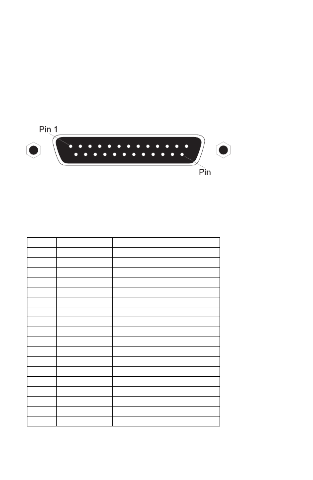
C
ABLES
B-5
Printer Port Pin Assignments
The DB-25 parallel port on the gateway’s rear panel is used to
connect the gateway to a printer. When a printer is attached to this
port, any PCs attached to the Barricade’s LAN ports can pass files
to the printer. The pin assignments used to connect to the printer
port are provided in the following table.
Figure B-3. DB-25 Printer Port Pin Numbers
DB-25 Printer Port Pin Assignments
Pin Signal Name Direction
1-Strobe To printer
2+Data 0 To printer
3+Data 1 To printer
4+Data 2 To printer
5+Data 3 To printer
6+Data 4 To printer
7+Data 5 To printer
8+Data 6 To printer
9+Data 7 To printer
10 - ACK To print server
11 + Busy To print server
12 + Paper End To print server
13 + Select To print server
14 - Auto Feed No connection
15 - Error To print server
16 - Init To printer
17 - Select No connection
18-25 GND Ground
25

C
ABLES
B-6

C-1
A
PPENDIX
C
S
PECIFICATIONS
WAN Interface
10BASE-T, 1 RJ-45 port
Serial, 1 RS232 DB-9 connector
LAN Interface
10BASE-T/100BASE-TX
3 RJ-45 ports
WLAN Interface
Standard: IEEE 802.11b, Direct Sequence Spread Spectrum (DSSS)
Transmission Rate: 11 Mbps, with fallback to 5, 2 or 1 Mbps
Maximum Channels: US/Canada: 11, Europe (ETSI): 13, Japan: 14
Range: 100 ft (30m) at 11 Mbps, 300 ft (100m) at 5.5 Mbps or lower
Frequency: US/Canada/ETSI: 2.400-2.4835 GHz, Japan: 2.471-2.497 GHz
Sensitivity: 1, 2, 5.5 Mbps: -80 dBm; 11 Mbps: -76 dBm typical
Modulation: CCK, BPSK, QPSK
Encryption: 64-bit WEP
Maximum Clients: 20
Printer Interface
Parallel
1 DB-25 printer port

S
PECIFICATIONS
C-2
Management
Web management
Advanced Features
Dynamic IP Address Configuration – DHCP, DNS
Firewall – Client privileges, hacker prevention and logging, NAT
Virtual Private Network – PPTP, L2TP, IPSec
Backup Internet Connection –
Dial-on-demand via secondary WAN port
Print server
Internet Standards
ARP (RFC 826), IP (RFC 791), ICMP (RFC 792), UDP (RFC 768),
TCP (RFC 793), Telnet (RFC 854-859), MD5 (RFC 1321), BOOTP
Extension (RFC 1497), PPP LCP Extension (RFC 1570), PPPoE
(RFC 2516), NAT (RFC 1631), PPP (RFC 1661), HTML (RFC 1866),
HTTP (RFC 1945), CHAP (RFC 1944), DHCP (RFC 2131), PPTP
(RFC 2637)
Indicator Panel
WAN, WLAN, LAN (Link, Activity), Power
Dimensions
22.0 x 18.1 x 4.3 cm (8.7 x 7.15 x 1.6 in)
Weight
2.26 lbs (1.023 kg)
Input Power
5V DC (2.0A)
Maximum Current
0.40A RMS max.@110V, 0.87A RMS max.@240V
Power Consumption
10 Watts max. @ 100-240 VAC
Heat Dissipation
34.1 BTU/hr max. @ 100-240 VAC

S
PECIFICATIONS
C-3
Temperature
Operating 32 to 104°F (0 to 40°C)
Storage -40 to 158°F (-40 to 70°C)
Humidity
5% to 95% (noncondensing)
Compliances
CE Mark
Emissions
FCC Class B
VCCI Class B
Industry Canada Class B
EN55022 (CISPR 22) Class B
C-Tick - AS/NZS 3548 (1995) Class B
ETS 300 328
MPT RCR STD-33
Immunity
IEC 1000-4-2/3/4/6
Safety
UL 1950
EN60950 (TÜV)
CSA 22.2 No. 950
Warranty
Limited Lifetime

S
PECIFICATIONS
C-4

D-1
A
PPENDIX
D
O
RDERING
I
NFORMATION
Barricade Broadband Router Products
SMC7004ABR Residential Gateway - WAN/LAN/Print Server
SMC7004AWBR Residential Gateway - WAN/LAN/Print Server
(with wireless)

O
RDERING
I
NFORMATION
D-2

6 Hughes
Irvine, CA 92618
Phone: (949) 707-2400
FOR TECHNICAL SUPPORT, CALL:
From U.S.A. and Canada (24 hours, 7 days a week)
(800) SMC-4-YOU; (949) 707-2400; (949) 707-2460 (Fax)
From Europe (8:00 AM - 5:30 PM UK Greenwich Mean Time)
44 (0) 1188 748740; 44 (0) 1189 748741 (Fax)
INTERNET
E-mail addresses:
techsupport@smc.com
european.techsupport@smc-europe.com
Driver updates:
http://www.smc.com/support.html
World Wide Web:
http://www.smc.com/
FTP Site:
ftp.smc.com
FOR LITERATURE OR ADVERTISING RESPONSE, CALL:
U.S.A. and Canada: (800) SMC-4-YOU; Fax (949) 707-2460
Spain: 34-93-477-4920; Fax 34-93-477-3774
UK: 44 (0) 1188 748700; Fax 44 (0) 1189 748701
Southern Europe: 33 (1) 41.18.68.68; Fax 33 (1) 41.18.68.69
Central/Eastern Europe: 49 (0) 89 92861-200; Fax 49 (0) 89 92861-230
Nordic: 46 (8) 564 33145; Fax 46 (8) 87 62 62
Middle East: 971-48818410; Fax 971-48817993
South Africa: 27 (0) 11-3936491; Fax 27 (0) 11-3936491
PRC: 86-10-6235-4958; Fax 86-10-6235-4962
Taiwan: 886-2-2747-4780; Fax 886-2-2747-9220
Asia Pacific: (65) 238 6556; Fax (65) 238 6466
Korea: 82-2-553-0860; Fax 82-2-553-7202
Japan: 81-45-224-2332; Fax 81-45-224-2331
Australia: 61-2-9416-0437; Fax 61-2-9416-0474
India: 91-22-8204437; Fax 91-22-8204443
Model Number: SMC7004AWBR
Revision Number: E052001-R01
Firmware Version 0.01