Accton Technology WG3005BACC Wireless Cable/DSL Gateway 3CRWE51196 User Manual 3c51196 ug
Accton Technology Corp Wireless Cable/DSL Gateway 3CRWE51196 3c51196 ug
Contents
Users manual 2

5GATEWAY CONFIGURATION
Navigating Through
the Gateway
Configuration Pages
This chapter describes all the screens available through the Gateway configuration
pages, and is provided as a reference. To get to the configuration pages, browse
to the Gateway by entering the URL in the location bar of your browser. The
default URL is http://192.168.1.1, but if you changed the Gateway LAN IP
address during initial configuration, use the new IP address instead. When you
have browsed to the Gateway, login using your system password (default admin).
Main Menu At the left side of all screens is a main menu, as shown in Figure 24 on page 32.
When you click on a topic from the main menu, that page will appear in the main
part of the screen.
■Welcome - displays the firmware version of the Gateway, allows you to change
your password, and launch the Wizard
■LAN Settings - allows you to configure IP address and subnet mask information,
setup DHCP server parameters, and display the DHCP client list.
■Wireless Settings - enables / disables access from wireless computers, and
provides facilities for improving the security of the wireless network.
■Internet Settings - sets up Internet addressing modes such as PPPoE
connection, dynamic IP address allocation and static IP address settings
■Firewall - allows configuration of the Gateway’s firewall features: Virtual
Servers, Special Applications, PCs Privileges and security options
■System Tools - allows the administrator to perform maintenance activities on
the Gateway.
■Status and Logs - displays the current status and activity logs of the Gateway.
■Support - contains a comprehensive online help system
Option Tabs Each corresponding menu page may also provide sub-sections which are accessed
through the use of tabs (see Figure 24 for example). To access a sub-section,
simply click on the required tab.
Getting Help
On every screen, a Help button is available that provides access to the
context-sensitive online help system. Click this button for further assistance and
guidance relating to the current screen.
32 CHAPTER 5: GATEWAY CONFIGURATION
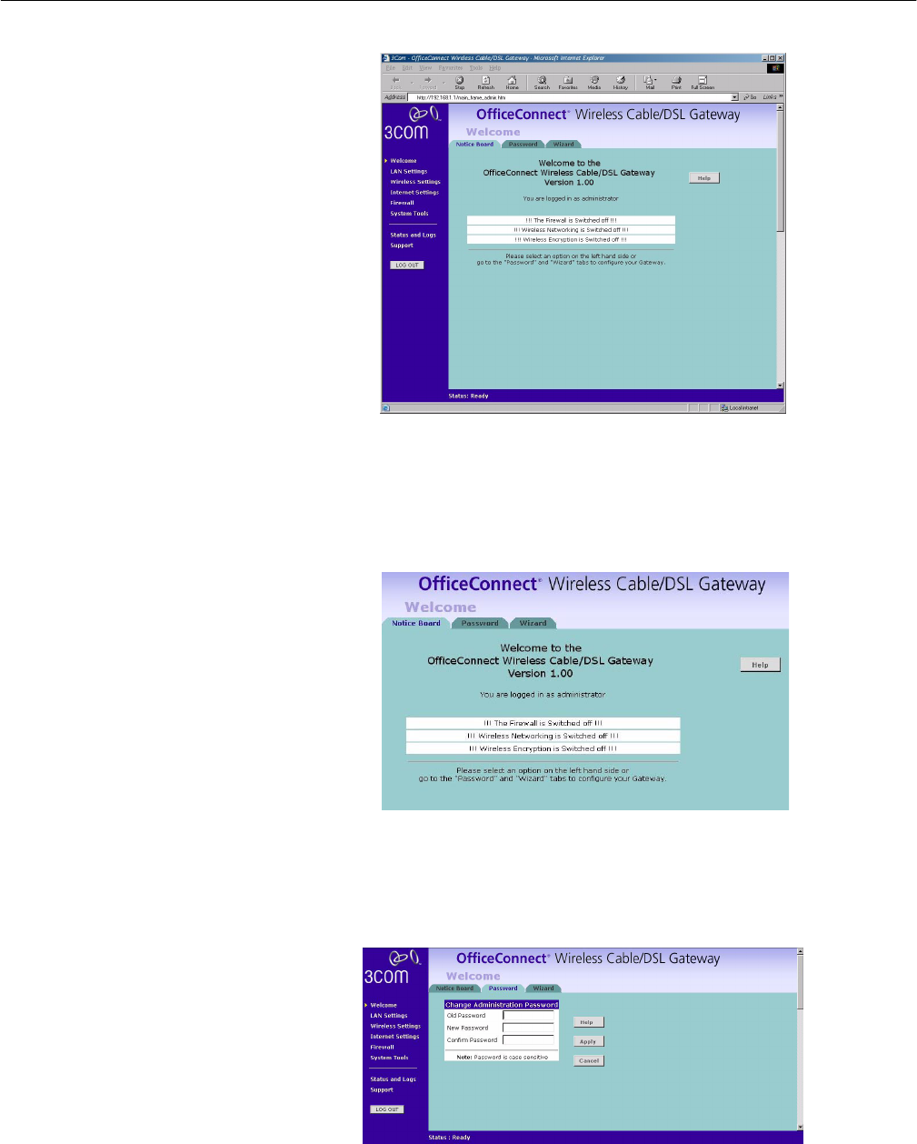
Welcome Screen Figure 24 OfficeConnect Wireless Cable/DSL Gateway Welcome Screen
The Welcome section allows you to view the Notice board and to change your
Password. You can also gain access to the Configuration Wizard. (See "Accessing
the Wizard" on page 23 for details.)
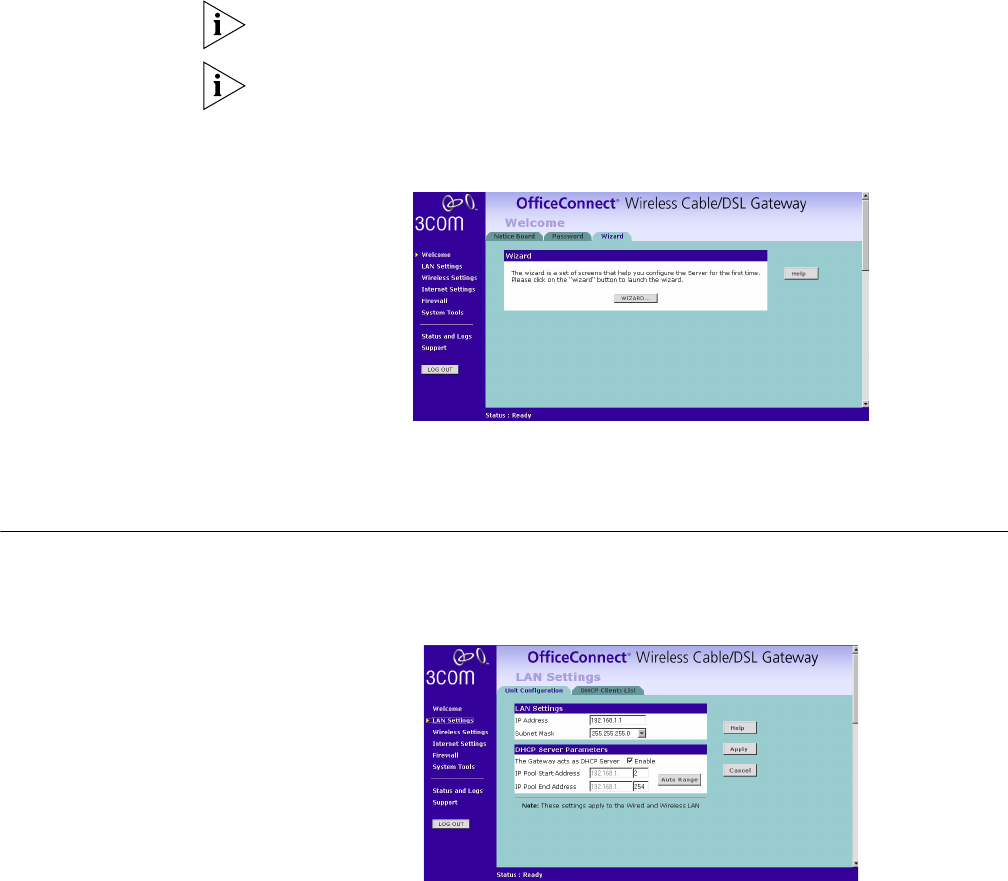
Notice Board Figure 25 Notice Board Screen
The Notice Board is used to display configuration warning messages. For example,
you would be warned if you had disabled the Firewall.
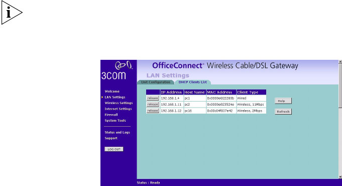
Password Figure 26 Password Screen
LAN Settings 33
Changing the Administration Password
You can change the password to prevent unauthorized access to the
Administration System. To do this:
1Enter the current password in the Old Password field
2Enter the new password in the New Password field
3Enter the new password again in the Confirm Password field
4Click Apply to save the new password
The password is case sensitive.
If you have forgotten your password you can reset the Gateway. See "Forgotten
Password" on page 56.
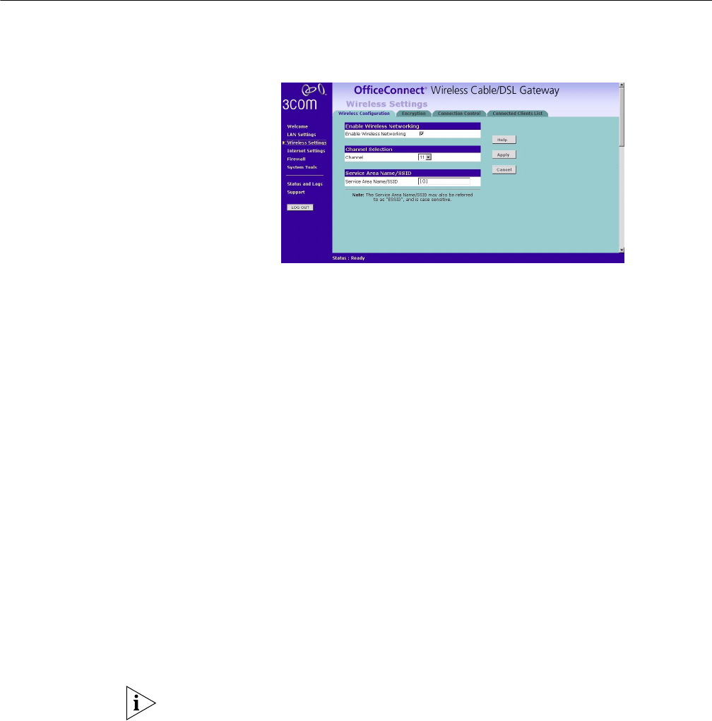
Wizard Figure 27 Wizard Screen
Click the WIZARD... button to launch the configuration wizard. Refer to Chapter 4
for information on how to run the wizard.
LAN Settings
Unit Configuration Figure 28 Unit Configuration Screen
34 CHAPTER 5: GATEWAY CONFIGURATION
The LAN Settings screen is used to specify the LAN IP address of your Gateway,
and to configure the DHCP server.
1Select Unit Configuration and then specify the Gateway IP Address and Subnet
Mask in the LAN Settings field. The default IP address of the Gateway is
192.168.1.1.
2If you want to use the OfficeConnect Wireless Cable/DSL Gateway as a DHCP
Server, click in the Enable check box.
3Clicking on Auto Range button will generate the IP pool address from 192.168.1.2
to 192.168.1.254 for the DHCP Server Parameters field. Auto Range will
automatically choose the largest available range of addresses.
4Check all of your settings, and then click Apply.
The DHCP server will give out addresses to both wired and wireless clients.
DHCP Clients List Figure 29 DHCP Clients List Screen
The DHCP Clients List provides details on the devices that are connected to the
LAN. The list is only created when the Gateway is setup as a DHCP server. For each
device that is connected to the LAN, the IP address, Host Name and MAC address
of that device is displayed. As you connect more devices to the LAN, the client list
will grow to a maximum number of clients, which is determined by the IP address
range.
The Release button allows the lease time for the IP address that has been issued to
a device to be cleared. The lease time is set at 12 hours. If a PC has been switched
off, using the Release Button would allow the 12 hour lease time to be cleared.
The IP address would then be available for another device if there were no other IP
addresses available.
As the IP address is fixed to a MAC address, then each particular computer will
normally be issued with the same IP address. The only time that a PC will get a
different IP address is if the unit is reset to factory defaults or the DHCP server has
run out of IP addresses.
Wireless Settings 35
Wireless Settings
Wireless Configuration Figure 30 Wireless Configuration Screen
Enable Wireless Networking
Allows you to enable/disable the wireless section of your LAN. When disabled, no
wireless PCs can gain access to either the Internet or other PCs on your Wired or
Wireless LAN.
Channel Selection
The Channel Selector allows you to specify which Channel the Gateway will
transmit and receive on. If someone else nearby is using the same Channel as you,
there will be a reduction in the performance of your network. If this seems to be
the case, you should select a different channel number. Valid Channels are 1- 13.
Usually the Wireless computers will scan to find the correct channel, but if they
don't you must configure them to use the same Channel number as the Gateway.
Service Area Name/SSID
This allows you to name your Wireless network. The field will accept any
alphanumeric string and has a maximum length of 32 characters. Your Wireless
computers must be configured with exactly the same name or you will not
establish a connection. The Service Area Name may also be referred to as "ESSID"
depending on your networking vendor. By default 3Com uses the name "101".
3Com recommends that you change the default name.
In order that your Wireless computers can connect to the Gateway, you must
configure them so that they :
■Use Infrastructure Mode not Adhoc Mode.
■Have the same Service Area Name as the Gateway.
■Have the same Channel number as the Gateway.
■Use the same encryption type and keys as the Gateway.
■All Wireless computers can connect to the Gateway via their MAC addresses.
See "Wireless Configuration Screen" on page 35)
36 CHAPTER 5: GATEWAY CONFIGURATION
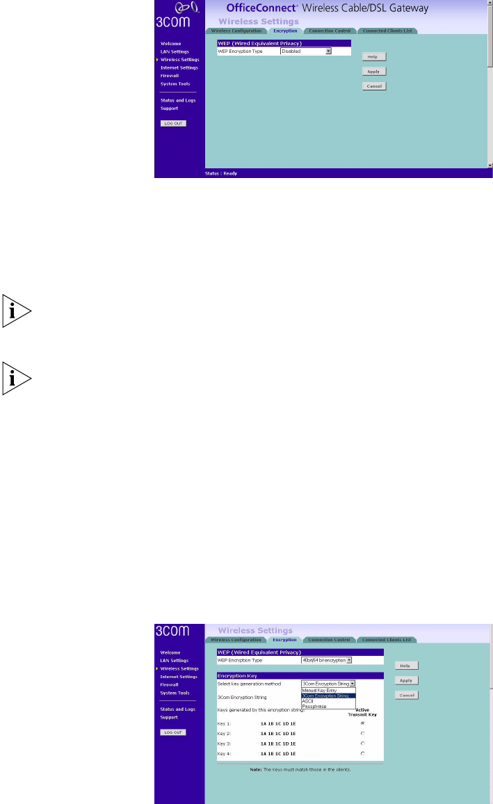
Encryption Figure 31 Encryption Screen
Wired Equivalent Privacy or WEP allows you to encrypt the traffic between your
Wireless PC and the Gateway. It is important to remember that with WEP disabled
anyone with a Wireless PC can eavesdrop on your network. 3Com recommends
that you get the network working with WEP disabled first and then enable it as
the last step. This will simplify setting up your network.
If you enable WEP on the Gateway, you must reconfigure your wireless PCs to use
exactly the same Encryption Type and Keys otherwise the devices will not
understand each other.
WEP is for securing data transmitted through wireless communications between
the Gateway and it's wireless clients. Enabling WEP has no security effect on data
transmitted through wired (Ethernet) connections or through your connections to
the Internet.
Wireless Encryption Type
There are two levels of encryption available, 64 bit (sometimes referred to as 40
bit) and 128 bit. 128 bit will result in a higher level of security, but may cause a
slight decrease in performance. Use the "Wireless Encryption Type" box to select
the desired level.
Encryption Keys
Figure 32 Encryption Keys Screen
A Key is a hexadecimal (0-9, A-F) number used to encrypt and decrypt the data.
There can be up to 4 keys and each key can be as long as 26 digits. The Gateway
also offers a number of methods for converting plain text into hex keys. The text is
much easier to remember than hex keys but it relies on your wireless adapters also

Wireless Settings 37
supporting this feature. Different manufacturers have developed different ways of
converting plain text and so interoperability is not guaranteed. If you are
experiencing difficulty, the Manual Hex Key method is supported by most vendors.
There are four methods available to generate the encryption keys:
■Manual Key Entry - This method allows you to manually enter hex keys.
Virtually all manufacturers support this scheme. Enter a two digit hexadecimal
number in every box. Hexadecimal numbers are formed from 0-9 and A-F.
■3Com Encryption String- This method is supported by 3Com Wireless products.
The string can contain any alpha numeric characters and must be between 6
and 30 characters long. A single string will automatically generate 4 unique
keys for 64 or 128 bit WEP.
■ASCII - This method is supported by some adapter cards running under
Windows XP. The string must be exactly 5 characters for 64 bit WEP and 13
characters for 128 bit WEP. You must enter a separate string for each of the 4
Keys. You can leave a string blank provided this Key is not selected as the
Active Transmit Key.
■Passphrase - This is another common method and similar to the 3Com
Encryption string. In 64 bit WEP, the Passphrase will generate 4 different keys.
However, in 128 bit WEP, this method only generates 1 key which is replicated
for all 4 keys. The passphrase can be up to 31 characters long and may contain
any alpha numeric or symbol characters.
Select from the drop down list the key generation method you wish to use. If you
have other wireless products choose the scheme that is compatible with these,
then enter the appropriate information.
If you encounter any difficulty when you enable WEP ensure that you check that
each Key on your wireless computer is exactly the same as each key on your
Gateway. In other words, Key number 1 on the Wireless computer must have the
same Hex number as Key number 1 on the Gateway, Key 2 on the Wireless
computer must match Key 2 on the Gateway and so on.
The "Active Transmit Key" selects which of the 4 Keys the Gateway uses when it
transmits. You can change the selected key periodically to increase the security of
your network. Your wireless computers do not need to use the same Active
Transmit Key number as your Gateway - so you could for example select Key 2 on
the Gateway and Key 4 on your computers.
Some wireless adapters have only one key available on their WEP configuration
page. If this is the case ensure it is the same as Key 1 on the Gateway and that it is
selected as the active transmit key.
38 CHAPTER 5: GATEWAY CONFIGURATION
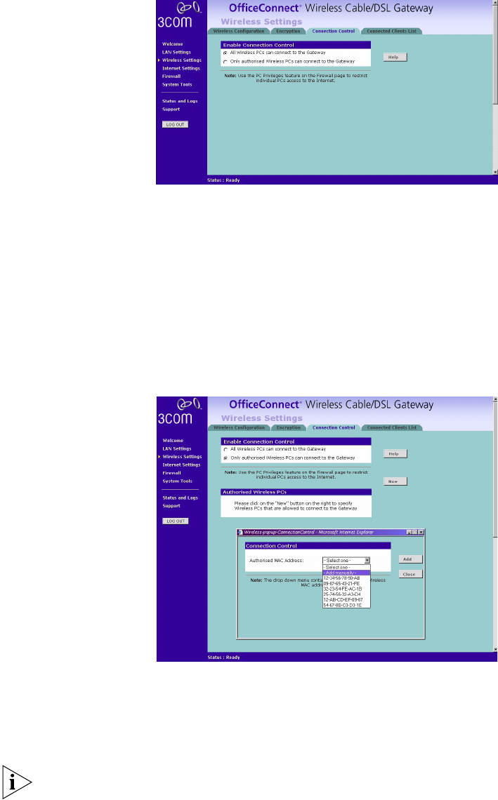
Connection Control Figure 33 Connection Control Screen
A higher level of security can be achieved for your wireless network if you use
both encryption and you specify only certain wireless computers can connect to
the Gateway. By default, any wireless computer that has the same Service Area
Name/SSID, channel and encryption settings as the Gateway can connect to it.
Select Only Authorised Wireless PC's can connect to the Gateway to configure this
feature.
Connected Client List
Figure 34 Connections Control Detail Screen
To create a list of Wireless computers that can access the Gateway:
1Press the New button.
2Specify the MAC address of the Wireless PC that is to be allowed to connect.
The drop down list on the "Add" window will contain the MAC addresses of all
Wireless PCs that are in range, currently operating, and have the same Service
Area Name/SSID, channel and encryption settings as the Gateway. You will find
this screen easier to use if you set up and make a note of all of your wireless PC's
on your network first. You may also add the entries manually if you know the
MAC address.

Wireless Settings 39
To add a MAC address that is not in the list, select "- Add Manually -" from the
list, and enter the MAC address in the appropriate fields. A MAC address consists
of 12 characters. Valid characters are '0-9', and 'A-F'.
3Press the Add button.
By pressing the Close button all changes will be discarded.
Modifying a MAC Address
1Click on the MAC address to be modified in the table.
2Modify the MAC address. The MAC address can be edited manually, or a different
MAC address may be selected from the drop down list of detected addresses.
3Press the Apply button to accept the changes.
By pressing the Close button all changes will be discarded.
40 CHAPTER 5: GATEWAY CONFIGURATION
Deleting a MAC Address
The connection rights for a Wireless PC listed in the table can be removed by
pressing the Delete button for that entry in the table.
Once an entry has been deleted it cannot be undone. Please wait 30 seconds
before changes take effect.
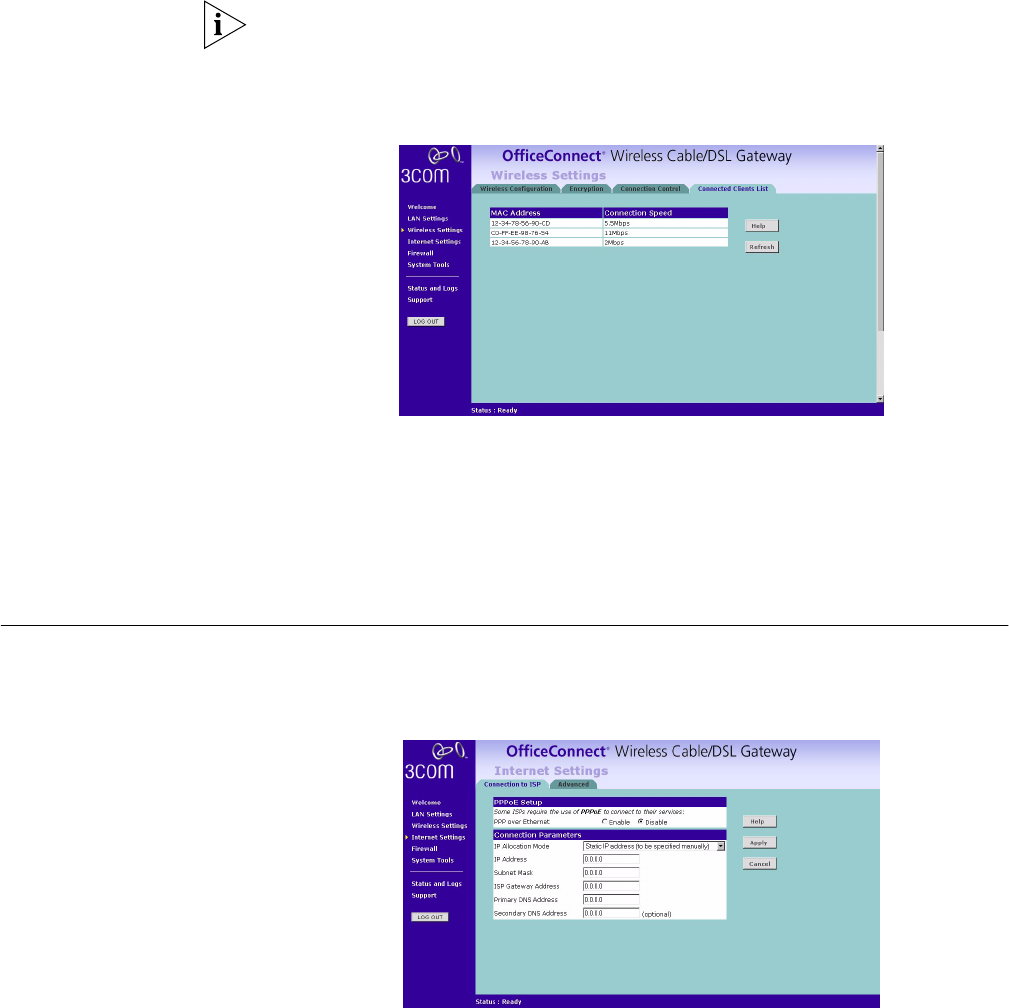
Connected Clients List Figure 35 Connected Clients List Screen
The Wireless Clients List provides details on the devices that are connected to the
Wireless LAN. The list is only created when Wireless Networking is enabled. For
each device that is connected to the Wireless LAN, the MAC address and
Connection Speed of that device is displayed. As you connect more devices to the
Wireless LAN, the client list will grow to a maximum of 32 (the maximum number
of wireless devices that the Gateway can support).
Internet Settings
Connection to ISP Figure 36 Connection to ISP Screen
Select Internet Settings from the main menu. Before beginning this section, ensure
you have the required information from your ISP. (See "Before you Install your
Gateway" on page 16.)
IP Allocation Mode If you enabled PPPoE, this field is automatically set to
Dynamic IP address (automatically allocated). If PPPoE is disabled, you will also be
able to select Static IP address (to be specified manually). If you are unsure which
setting you require, your ISP should be able to advise you.
Internet Settings 41
When the Cable/DSL Internet Settings > Connection to ISP page appears
(Figure 36), you will be asked to enter the information you received from your ISP.
If you have the information and your ISP has given you an IP address, enter the IP
address, subnet mask address, and ISP Gateway address in the appropriate text
boxes.
If your ISP has given you a DNS (Domain Name Server) address, fill in those
addresses.
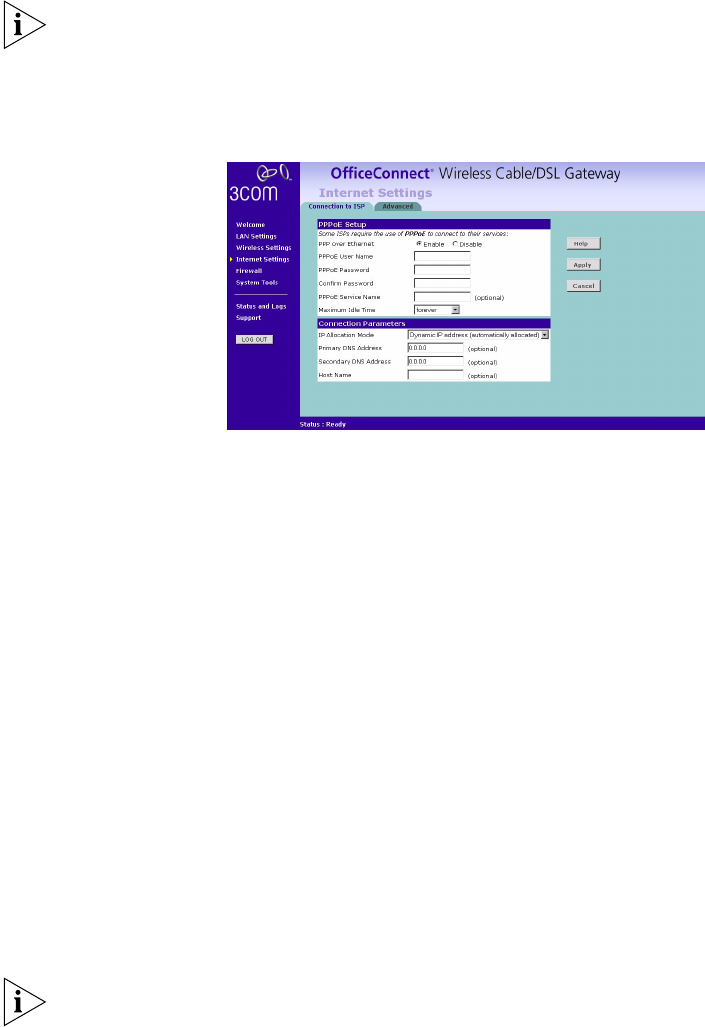
PPP over Ethernet connection
Figure 37 PPPoE Setup Screen
Some ISPs require the use of PPPoE in order to establish connections with their
networks. If you are unsure, you should ask your ISP whether you need to use
PPPoE.
Your ISP may need you to enter host name or PPPoE (Point-to-Point Protocol over
Ethernet) settings. To setup the Gateway for use with a PPP over Ethernet
connection, use the following procedure:
1Select Enable on the PPP over Ethernet option to display the PPPoE Setup screen.
(Figure 37)
2Enter your PPP over Ethernet user name in the PPPoE User Name text box.
3Enter a password in the PPPoE Password and Confirm Password text boxes.
4Enter your PPP over Ethernet service name in the PPPoE Service Name text box.
Not all ISPs require a PPPoE service name. Only enter a service name if your ISP
requires this.
5Select an idle time from the Maximum Idle Time drop-down list.
This value will correspond to the amount of idle time (no Internet activity), in
seconds, that will pass before the Gateway automatically ends your PPP over
Ethernet session.
Since the Gateway firmware contains its own PPPoE client proxy, you no longer
need to run PPPoE client software on your computer to access the Internet. You
can simply start your browser and connect to the Internet immediately after
setting up your cable or DSL modem.
42 CHAPTER 5: GATEWAY CONFIGURATION
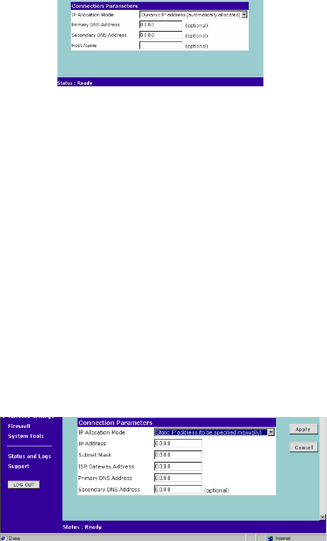
Dynamic IP Address
Figure 38 Connection Parameters Screen - Dynamic IP
If this mode is selected, your IP Address, Subnet Mask, and DNS Address will be
obtained automatically from your ISP. They are not displayed on this screen, but
may be viewed on the Status screen (click on Status and Logs on the left hand
menu bar).
To setup the Gateway for use with a dynamic IP address connection:
1Select Dynamic IP Address (automatically allocated) in the IP Allocation Mode field.
(Figure 38)
2Enter your primary and secondary DNS addresses.
Your ISP should provide your primary and (optional) secondary DNS addresses.
Enter the addresses in the appropriate text boxes. If you are using the DHCP
option (which automatically assigns your IP address), the value
0.0.0.0
will already by entered in the text box.
3Enter the Host Name (optional).
Some ISPs require a host name. If your ISP has this requirement, enter the host
name in the Host Name text box.
4When you are finished, click Apply.
Static IP Address
Figure 39 Connection Parameters Screen - Static IP
To setup the Gateway for use with a Static IP address connection:
1Select Static IP Address (to be specified manually) in the IP Allocation Mode field
(Figure 39).
2Enter your IP Address in the IP Address text box.
Firewall 43
This information, along with the rest of the information in this screen, should be
provided to you by your ISP. If the information is already entered, your ISP has
provided it to you automatically, and you should go to step 7.
3Enter your subnet mask address in the Subnet Mask text box.
4Enter your ISP Gateway address in the ISP Gateway Address text box.
5Enter your primary DNS address in the Primary DNS Address text box.
6Enter your secondary DNS address in the Secondary DNS Address text box.
This step is optional. Not all ISPs require a secondary DNS address.
7Check all of your settings, and then click Apply.
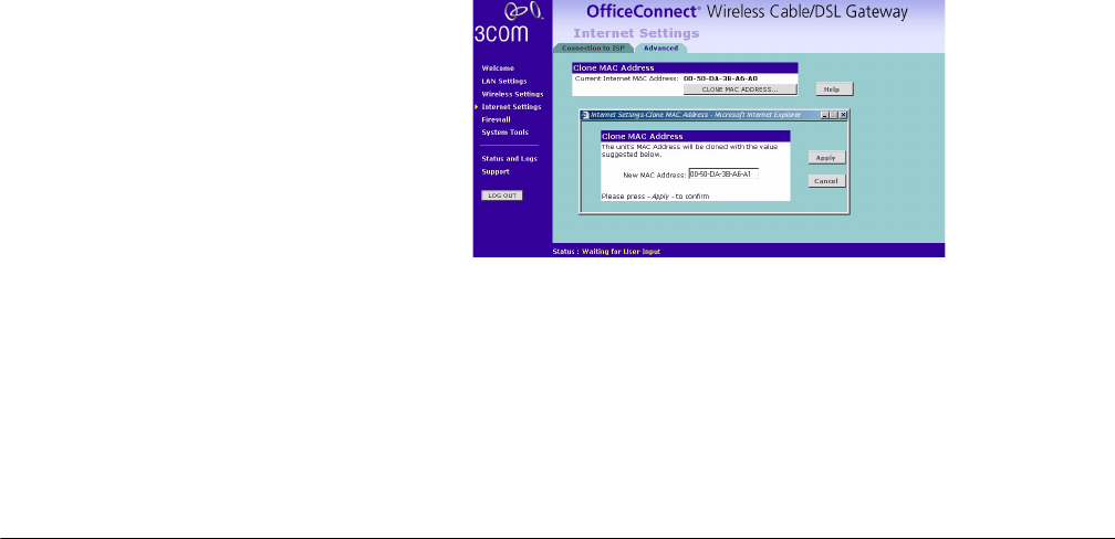
Advanced Clone MAC
Figure 40 Clone MAC Address Screen
If your ISP requires an assigned MAC address, click Internet Settings > Advanced
to display the Clone MAC Address screen. The New MAC Address field is
automatically filled in with the MAC address of the computer you are using to
configure the Gateway. You should use this address only if you were previously
using this computer to connect directly to your modem.
If you want to specify a new MAC Address, click on the CLONE MAC ADDRESS
button, enter a new MAC Address and then click Apply. (Figure 40)
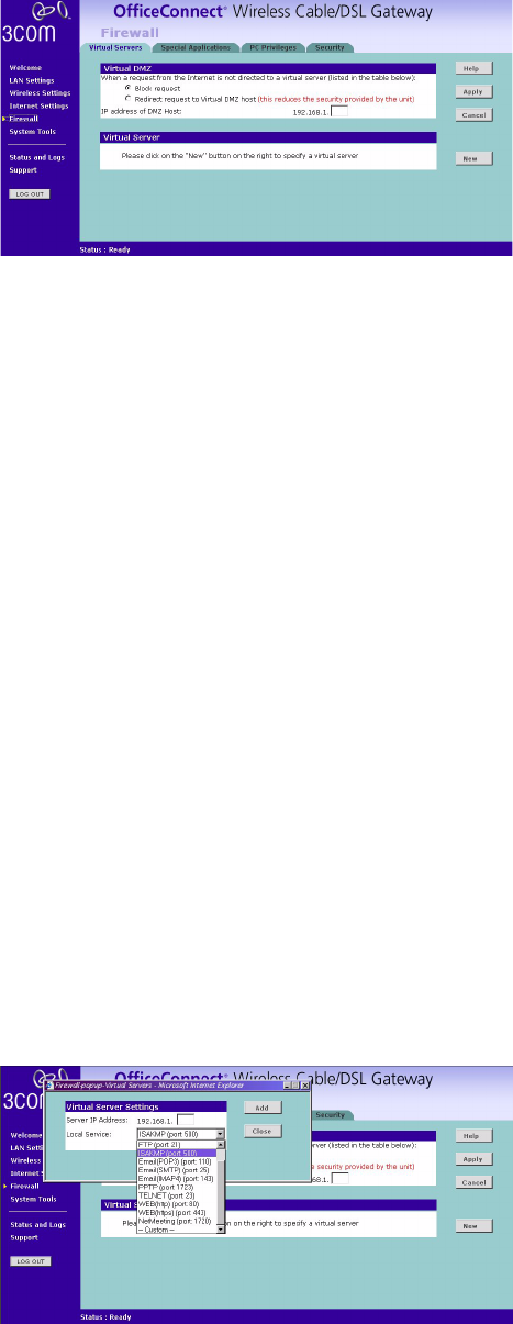
Firewall On the main frame of the Firewall setup screen is a menu with four tabs: Virtual
Servers, Special Applications, PCs Privileges, and Security.
Virtual Servers Selecting the Firewall option on the main menu displays the Virtual Servers setup
screen. (Figure 41)
44 CHAPTER 5: GATEWAY CONFIGURATION
Virtual DMZ
Figure 41 Virtual Servers Screen
DMZ (De-Militarized Zone) Host is a computer without the protection of the
firewall. This feature allows a single computer to be exposed to unrestricted 2-way
communication from outside of your network. This feature should be used only if
the Virtual Server or Special Applications options do not provide the level of access
needed for certain applications.
To configure one of your computers as a DMZ host, enter the last digit(s) of the IP
address of the computer in the IP Address of DMZ Host text box, and then click
the SAVE button.
Virtual Server
Activating and configuring a virtual server allows one or more of the computers on
your network to function as an Internet service host. For example, one of your
computers could be configured as an FTP host, allowing others outside of your
office network to download files of your choosing. Or, if you have created a Web
site, you can configure one of your computers as a Web server, so that others can
view your Web site.
To configure a virtual server:
1Click on the New button on the right side of the screen to open the Virtual Server
Settings dialogue box. (Figure 42)
2Enter the last digit(s) of the IP address of the computer in the Server IP Address
text box.
3Select the Service from the pull-down list. (Figure 42)
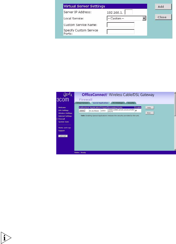
Figure 42 Virtual Servers Settings Screen
Firewall 45
Or Select Custom to specify a suitable name for the service and then enter the port
numbers required for that service. (Figure 43)
Figure 43 Custom Setup Screen
4Click Add button to save the settings.
The port numbers are specified using a comma-separated list, with hyphens to
denote port number ranges. So for example, entering 2, 3, 5-7 would cause ports
2, 3, 5, 6, and 7 to be activated.
Special Applications Figure 44 Special Applications Screen
Select Special Applications tab to display Authorized Application setup screen.
(Figure 44)
Some software applications require special or multiple connections to the Internet
and these would normally be blocked by the Firewall. For example Internet
Telephony or Video conferences require multiple connections.
So that these special applications can work properly and are not blocked, the
firewall needs to be told about them. In each instance there will be a trigger port
and incoming port(s), where traffic on the trigger port tells the Firewall to open
the incoming ports.
Each defined Special Application only supports a single computer user, and up to
10 Special Applications can be defined. Any incoming ports opened by a Special
Application trigger will be closed after five minutes of inactivity.
To configure special applications:
1Click on the New button.
2Select the applications from the pull-down list. (Figure 45)