Accton Wireless Broand FIU176205T01W 150 Mbps 4-Port Wireless Broadband Router User Manual user guide
Accton Wireless Broadband Corp. 150 Mbps 4-Port Wireless Broadband Router user guide
UserManual.wiki
>
Accton Wireless Broand
>
FIU176205T01W User Manual
Manual
Navigation menu
Upload a User Manual
Namespaces
Wiki Guide
HTML
PDF
Info
Views
User Manual
Discussion / Help
Navigation


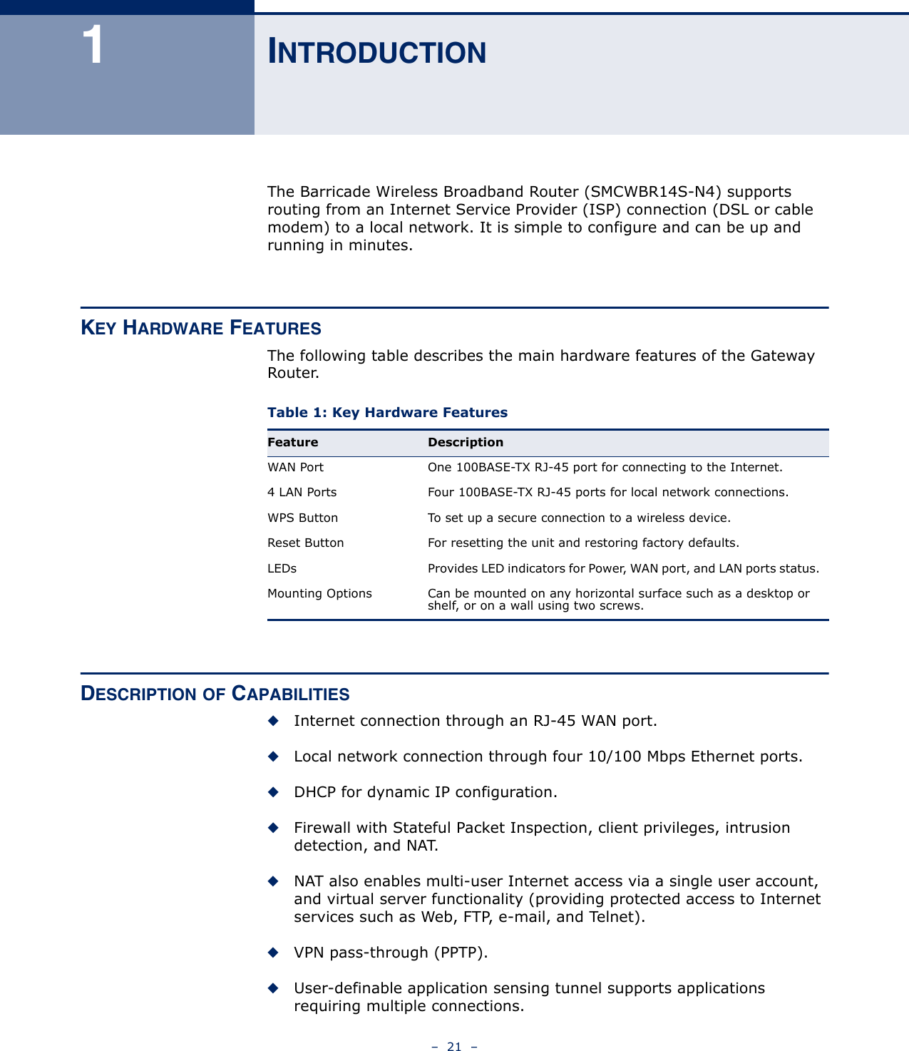


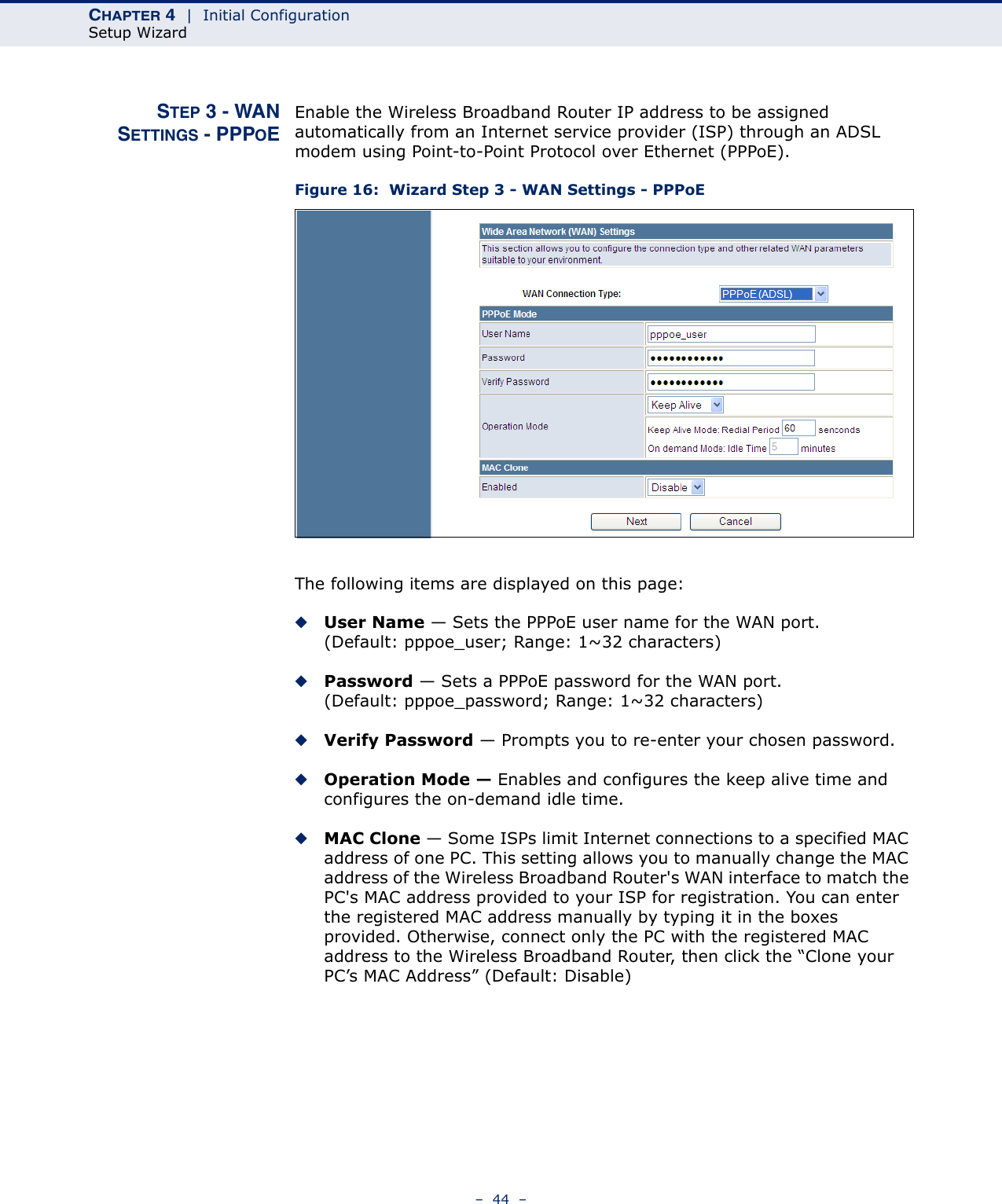
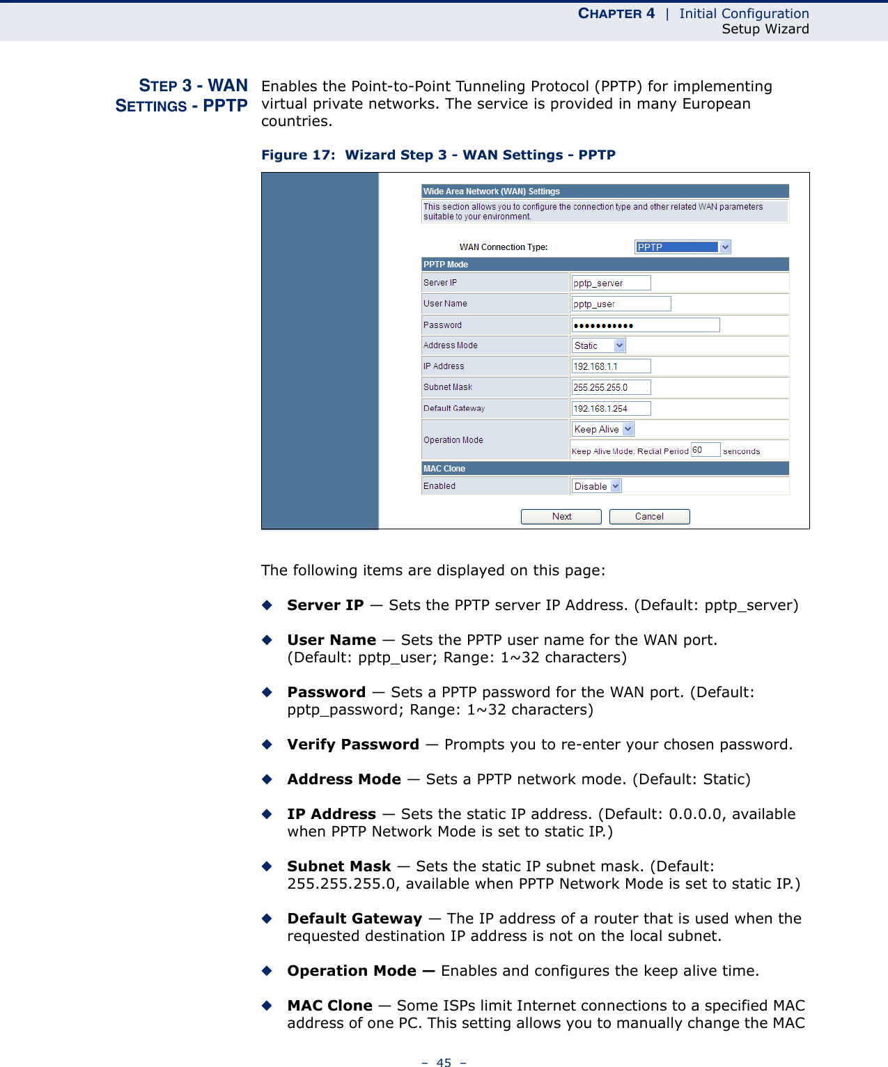
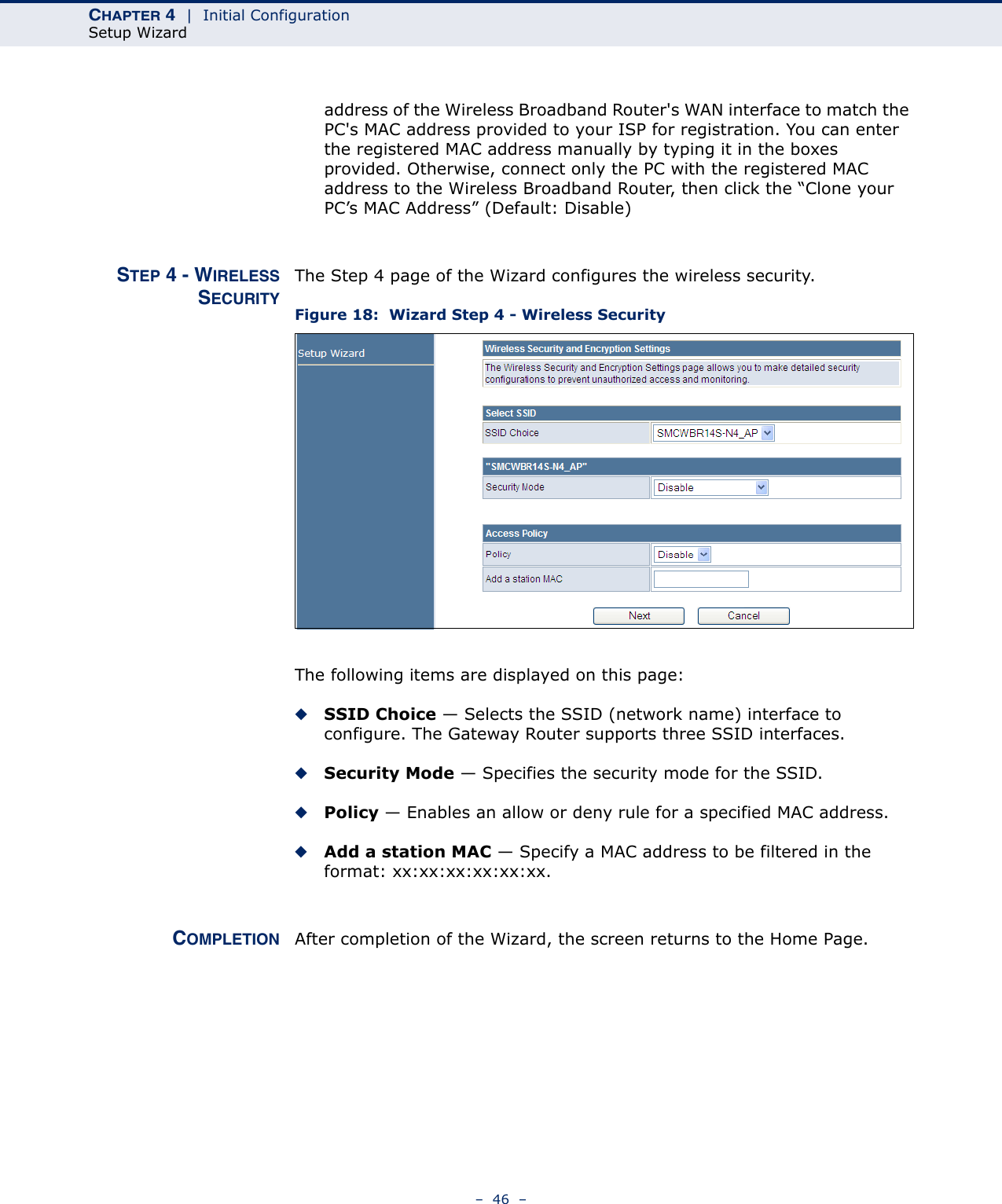

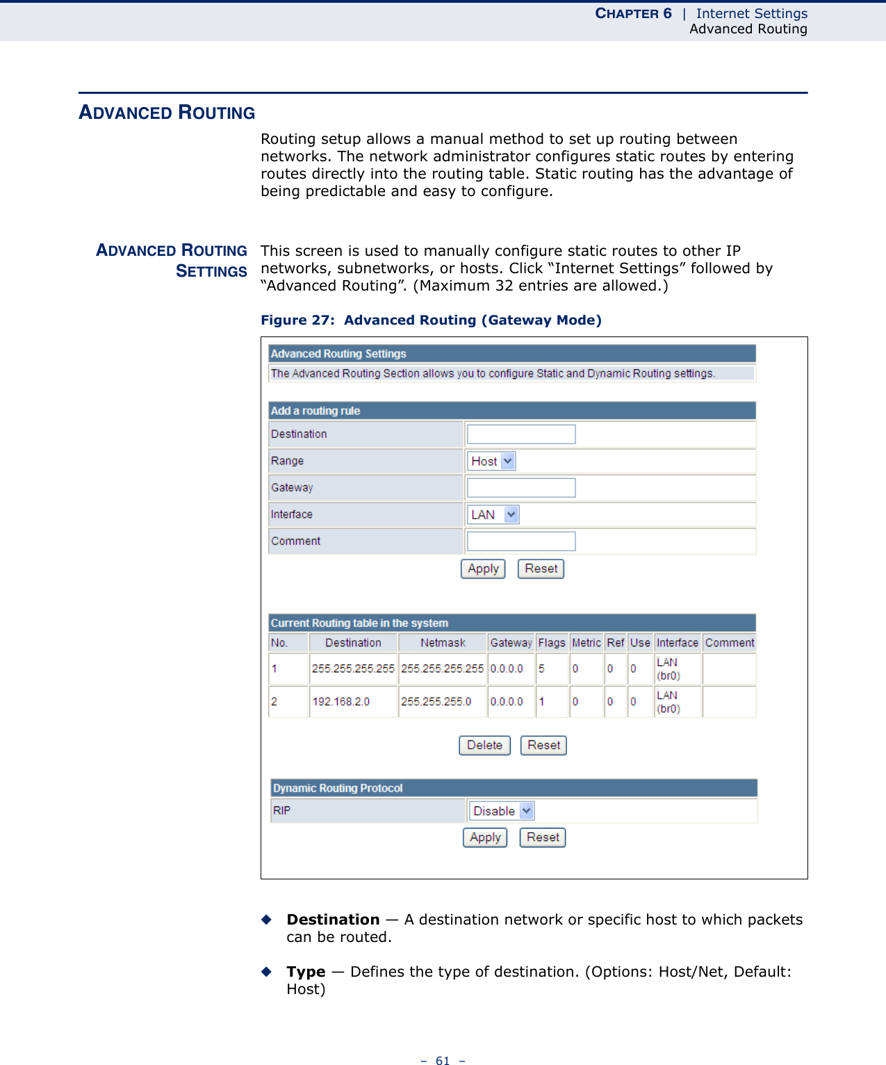

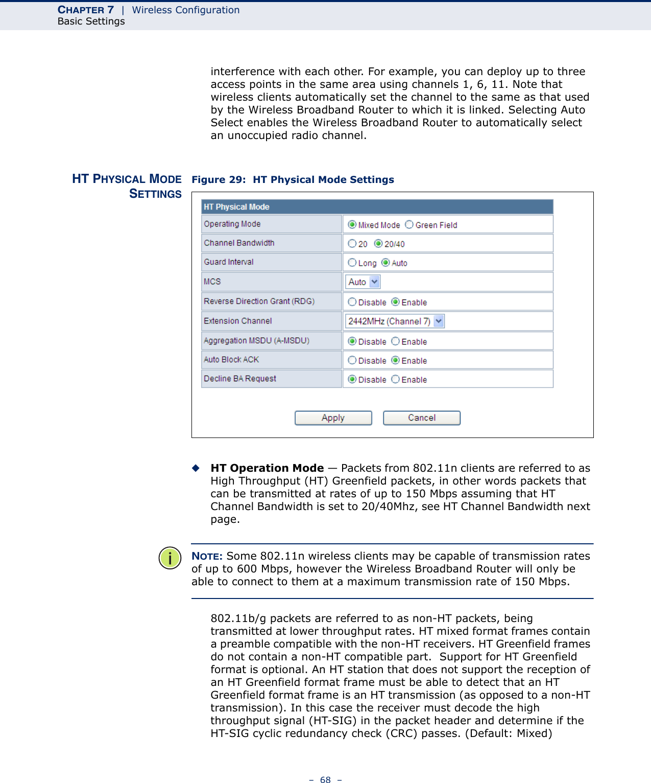
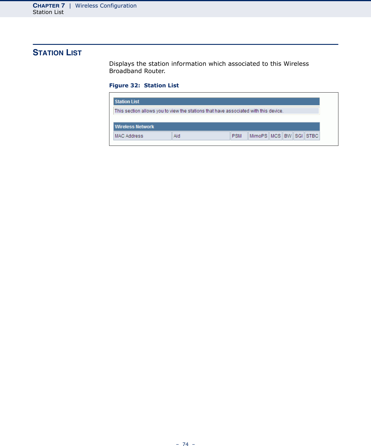
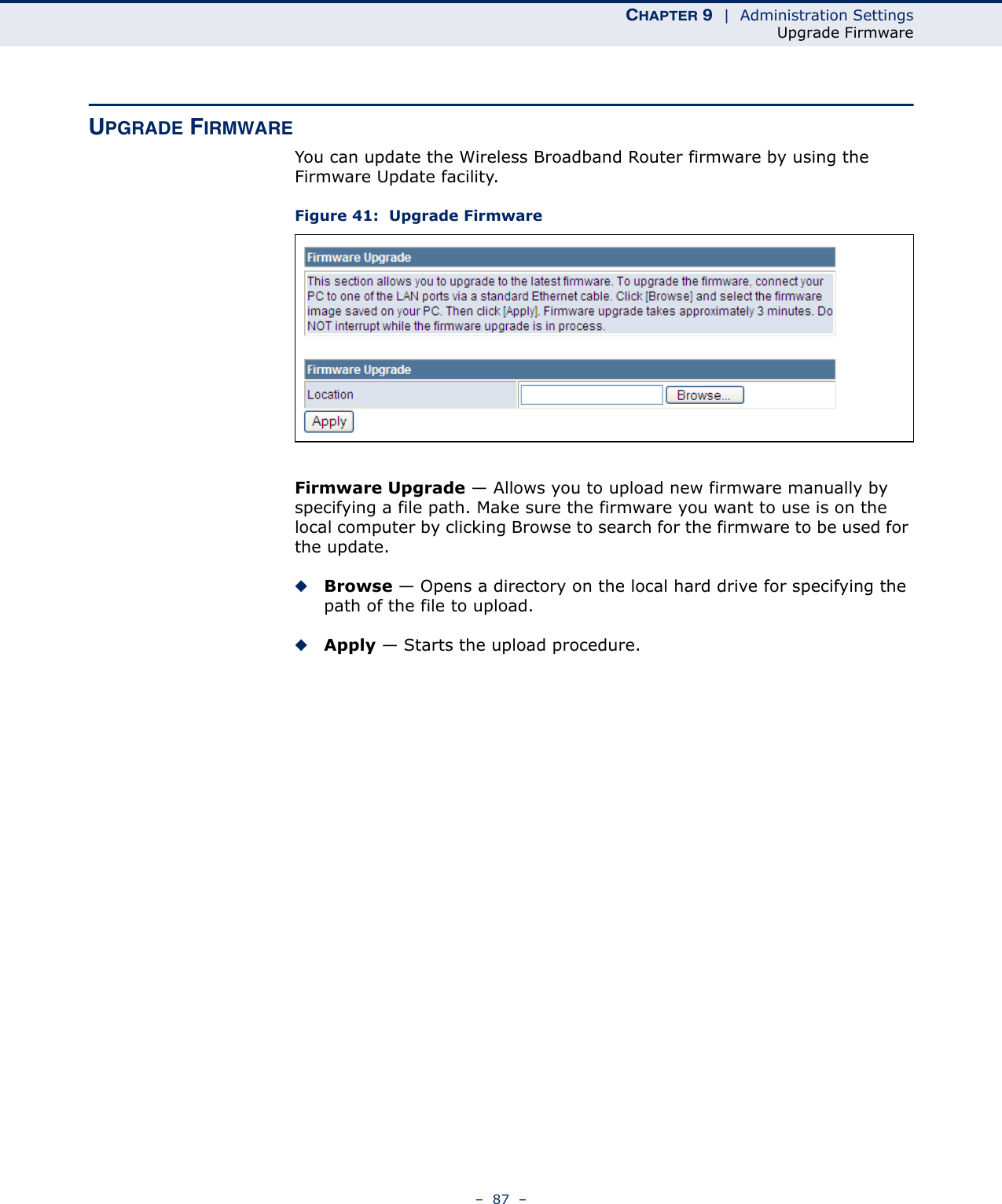
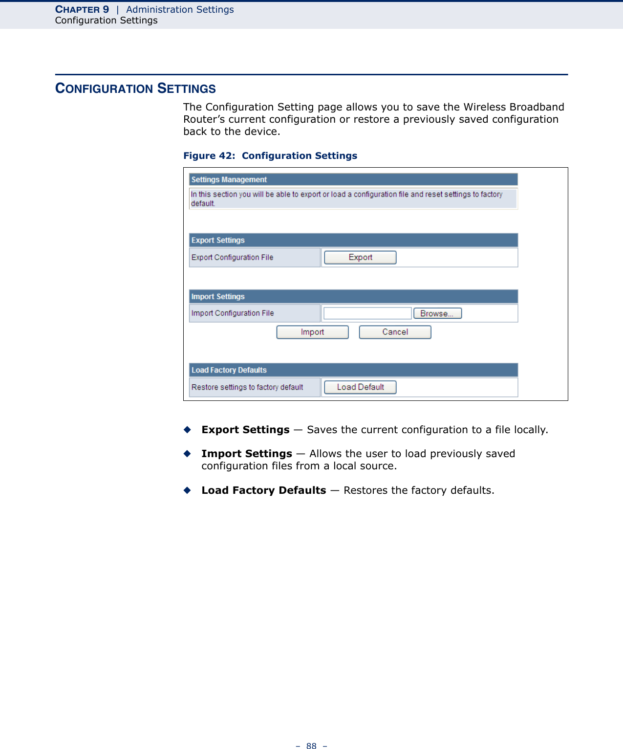
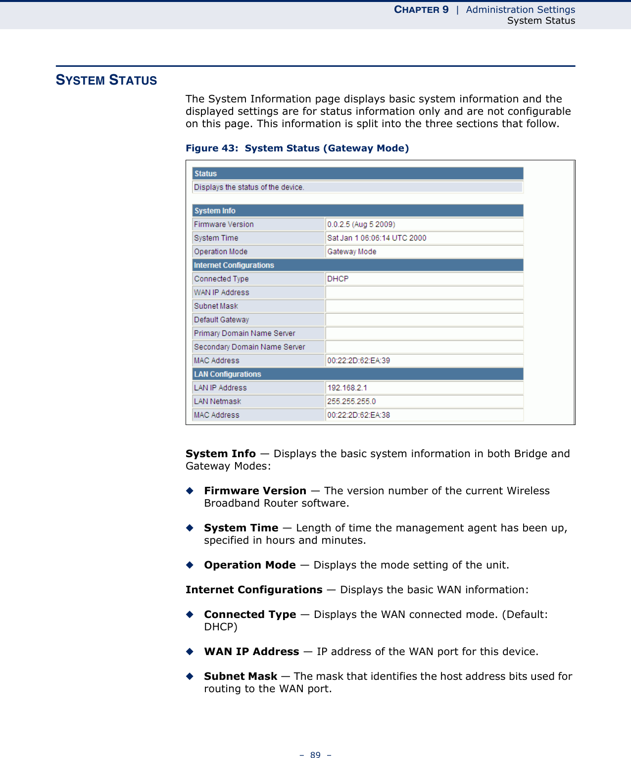
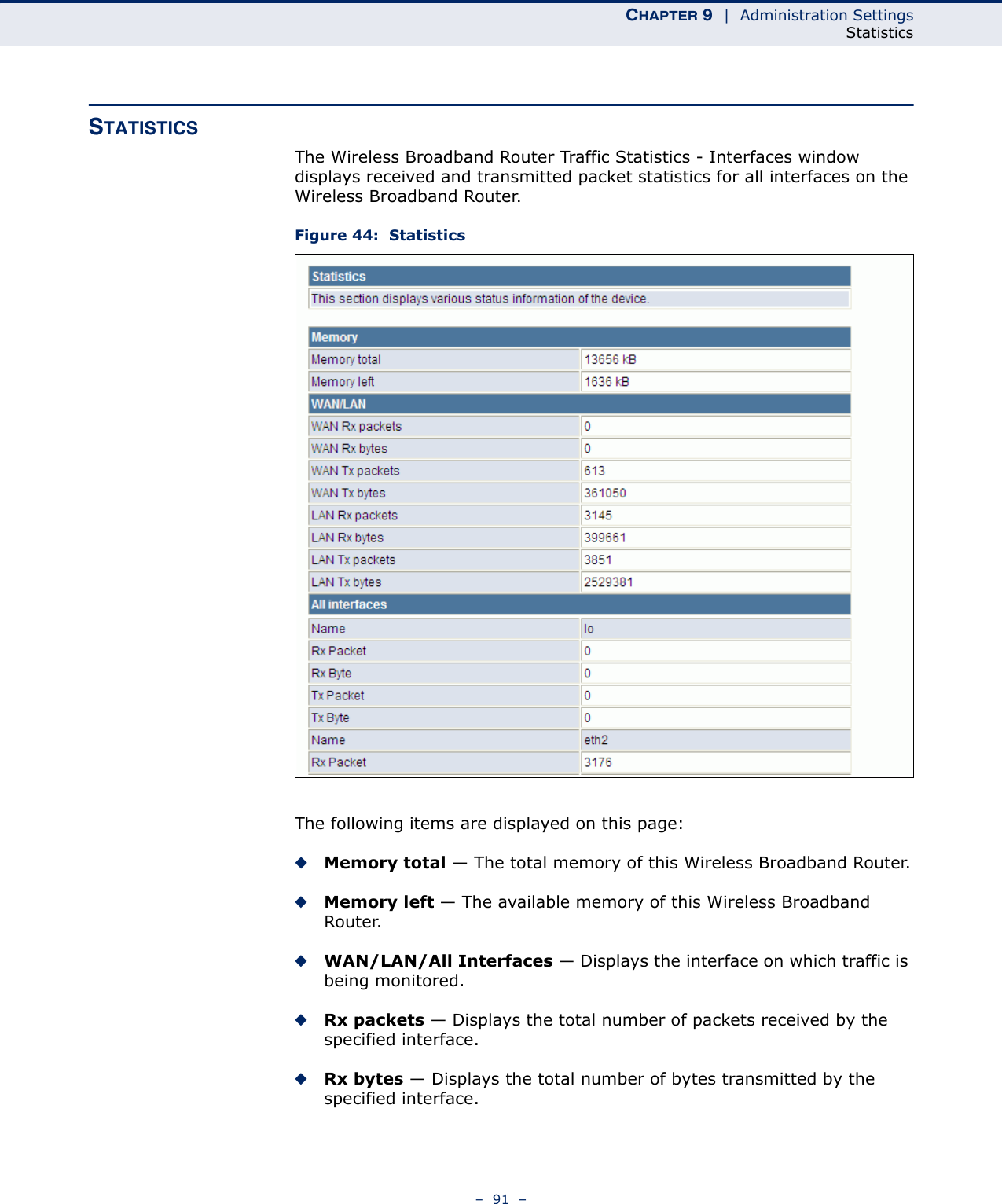
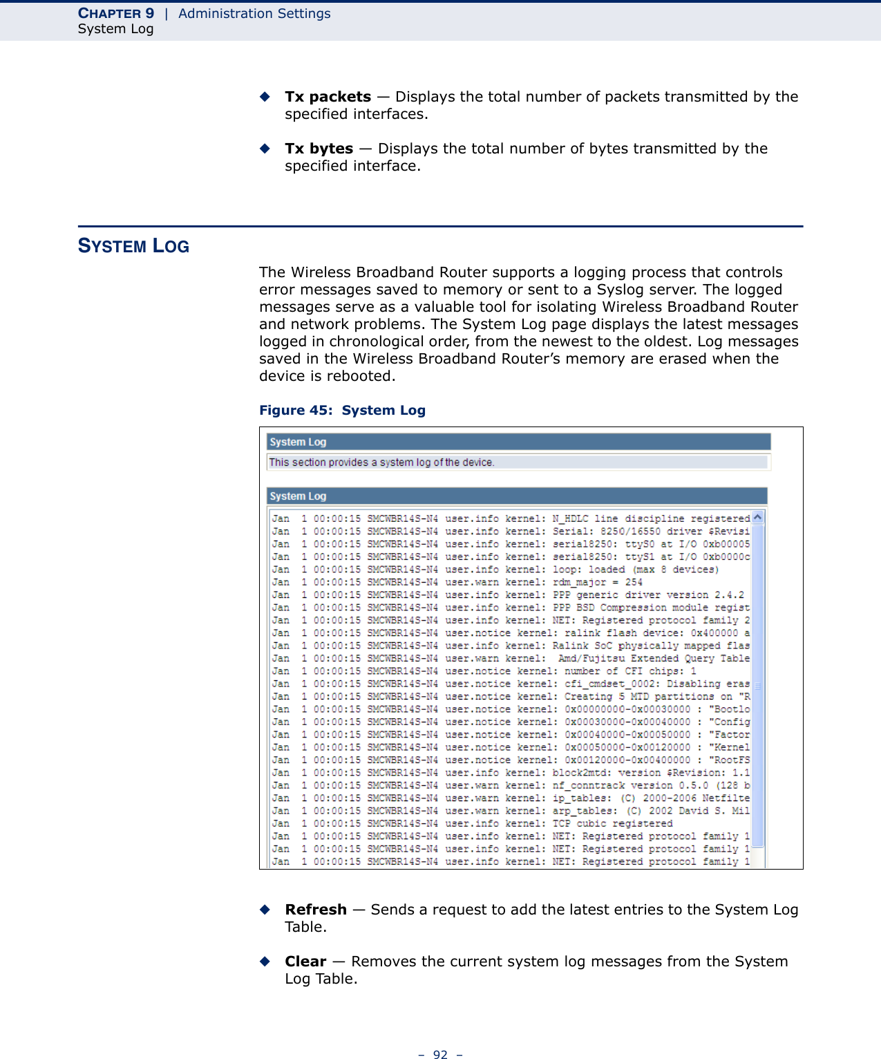
![CHAPTER 7 | Wireless ConfigurationWireless Distribution System (WDS)– 69 –◆HT Channel Bandwidth — The Wireless Broadband Router provides a channel bandwidth of 40 MHz by default giving an 802.11g connection speed of 108 Mbps (sometimes referred to as Turbo Mode) and a 802.11n connection speed of up to 150 Mbps. Setting the HT Channel Bandwidth to 20 MHz slows connection speed for 802.11g and 802.11n to 54 Mbps and 74 Mbps respectively and ensures backward compliance for slower 802.11b devices. (Default: 20/40MHz)◆Guard Interval — The guard interval between symbols helps receivers overcome the effects of multipath delays. When you add a guard time, the back portion of useful signal time is copied and appended to the front. (Default: Auto)◆MCS — The Modulation and Coding Scheme (MCS) is a value that determines the modulation, coding and number of spatial channels. (Options: value [range] = 0~7 (1 Tx Stream), 8~15 (2 TxStream), 32 and auto (33). Default: auto)◆Reverse Direction Grant (RDG) — When enables Reverse Direction Grant, the Wireless Broadband Router can reduce the transmitted data packet collision by using the reverse direction protocol. During TXOP (Transmission Opportunity) period, the receiver could use remaining transmission time to transmit data to a sender. The RDG improves transmission performance and scalability in a wireless environment. ◆Extension Channel — When 20/40MHz channel bandwidth has been set, the extension channel option will be enabled. The extension channel will allow you to get extra bandwidth. (Options: 2417MHz/Channel 2, 2457MHz/Channel 10. Default: 2457MHz/Channel 10.)◆Aggregate MSDU (A-MSDU) — This option enables Mac Service Data Unit (MSDU) aggregation. (Default: Disable)◆Auto Block ACK — Select to block ACK (Acknowledge Number) or not during data transferring.◆Decline BA Request — Select to reject peer BA-Request or not.WIRELESS DISTRIBUTION SYSTEM (WDS)The radio interface can be configured to operate in a mode that allows it to forward traffic directly to other Wireless Gateway Router units. To set up links between units, you must configure the Wireless Distribution System (WDS) forwarding table by specifying the wireless MAC address of all units to which you want to forward traffic.Traffic forwarded to WDS links is automatically converted to 802.11 four-address format frame. This uses the MAC addresses of the station and that of the AP connected to it on the transmitting LAN, and the MAC addresses of the AP functioning as a wireless repeater/bridge and that of the station connected to it on a neighboring LAN in the 802.11 frame header. Ethernet traffic follows a three-address format that is reconstructed for WDS](https://usermanual.wiki/Accton-Wireless-Broand/FIU176205T01W/User-Guide-1160306-Page-69.png)