Accton Wireless Broand FW181RG25020W WiMAX 802.16e Indoor CPE User Manual user guide
Accton Wireless Broadband Corp. WiMAX 802.16e Indoor CPE user guide
UserManual.wiki
>
Accton Wireless Broand
>
FW181RG25020W User Manual
User manual
Navigation menu
Upload a User Manual
Namespaces
Wiki Guide
HTML
PDF
Info
Views
User Manual
Discussion / Help
Navigation

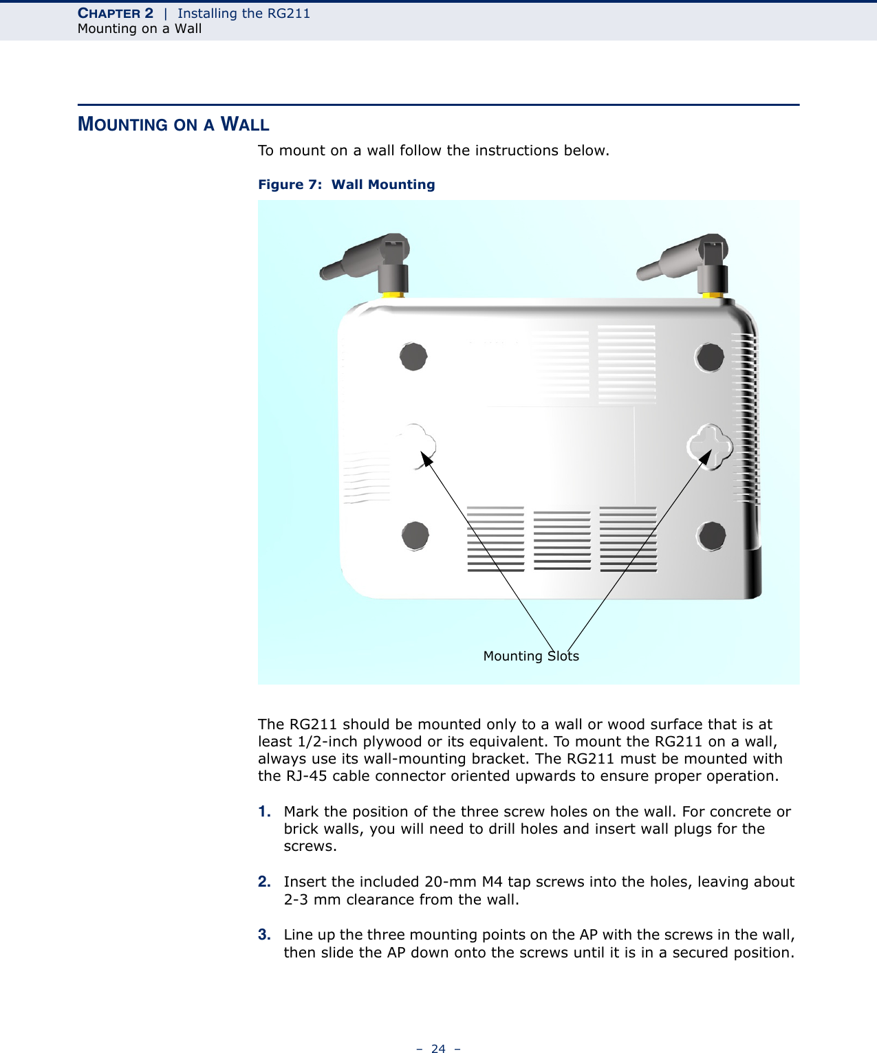


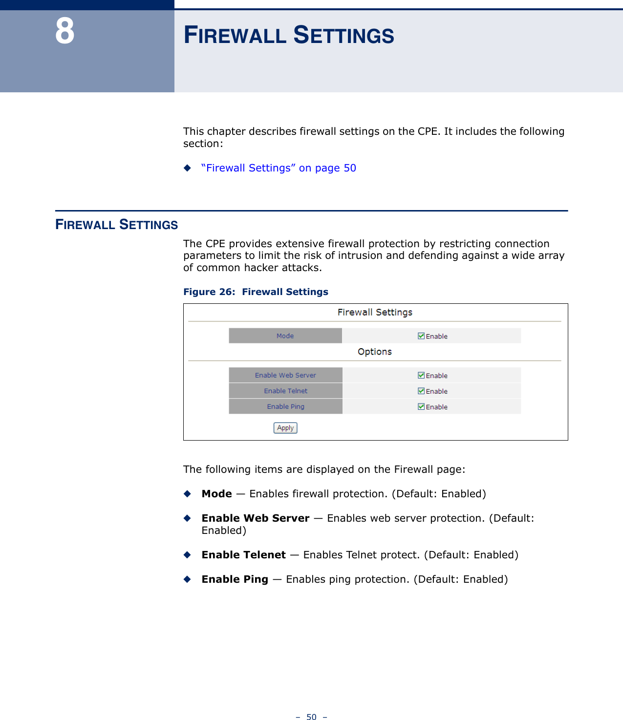

![CHAPTER 9 | Management SettingsChanging the Access Password– 53 –CHANGING THE ACCESS PASSWORDThe Change Password page enables you to create a new password for access to the CPE. It is advisable to change the factory default password upon receipt of your CPE device.Figure 28: Change PasswordThe following items are displayed on the Change Password page:◆Old Password — Prompts you to enter your current password.◆New Password — Prompts you to enter a new password. (Length: 1-20 characters, cannot include the characters ‘<>?:;,.’”{[}]/\|,’ and is case sentivitive.◆Confirm New Password — Prompts you to re-enter the new password.◆Save New Password — Clicking ‘Save New Password’ saves the new password and deletes the old password.◆Refresh — Clicking ‘Refresh’ clears all information boxes.](https://usermanual.wiki/Accton-Wireless-Broand/FW181RG25020W/User-Guide-1218159-Page-53.png)