Accton Wireless Broand FW181RG25020W WiMAX 802.16e Indoor CPE User Manual user guide
Accton Wireless Broadband Corp. WiMAX 802.16e Indoor CPE user guide
User manual

U
SER
G
UIDE
WIMAX 802.16E INDOOR CPE
RG211-2.3/2.5/3.5/3.8G

U
SER
G
UIDE
RG211-2.3/2.5/3.5/3.8G
WiMAX IEEE 802.16e Indoor CPE
RG211-81
E122009-DT-R01
149100000033W

– 3 –
COMPLIANCES
FEDERAL COMMUNICATION COMMISSION INTERFERENCE STATEMENT
This equipment has been tested and found to comply with the limits for a
Class B digital device, pursuant to Part 15 of the FCC Rules. These limits
are designed to provide reasonable protection against harmful interference
in a residential installation. This equipment generates, uses and can
radiate radio frequency energy and, if not installed and used in accordance
with the instructions, may cause harmful interference to radio
communications. However, there is no guarantee that interference will not
occur in a particular installation. If this equipment does cause harmful
interference to radio or television reception, which can be determined by
turning the equipment off and on, the user is encouraged to try to correct
the interference by one of the following measures:
◆Reorient or relocate the receiving antenna.
◆Increase the separation between the equipment and receiver.
◆Connect the equipment into an outlet on a circuit different from that to
which the receiver is connected.
◆Consult the dealer or an experienced radio/TV technician for help.
FCC Caution: Any changes or modifications not expressly approved by the
party responsible for compliance could void the user's authority to operate
this equipment.
This device complies with Part 15 of the FCC Rules. Operation is subject to
the following two conditions: (1) This device may not cause harmful
interference, and (2) this device must accept any interference received,
including interference that may cause undesired operation.
IMPORTANT NOTE:
FCC RADIATION
EXPOSURE
STATEMENT
This equipment complies with FCC radiation exposure limits set forth for an
uncontrolled environment. This equipment should be installed and
operated with minimum distance 20cm between the radiator & your body.
This transmitter must not be co-located or operating in conjunction with
any other antenna or transmitter.
Due to the essential high output power natural of WiMAX device, use of this
device with other transmitter at the same time may exceed the FCC RF
exposure limit and such usage must be prohibited (unless such co-
transmission has been approved by FCC in the future).

C
OMPLIANCES
– 4 –
EC CONFORMANCE
DECLARATION
Marking by the above symbol indicates compliance with the Essential
Requirements of the R&TTE Directive of the European Union (1999/5/EC).
This equipment meets the following conformance standards:
EN 60950-1 (IEC 60950-1) - Product Safety
EN 301 489-1, EN 301 489-4 - EMC requirements for radio equipment
EN 302 326-1-2-3
EN 50385 - Country specific SAR requirements
This device is intended for use in all European Community countries.
– 5 –
ABOUT THIS GUIDE
PURPOSE This guide gives specific information on how to install the WiMAX Indoor
CPE (Consumer Premise Equipment, from herein CPE) and its physical and
performance related characteristics. It also gives information on how to
operate and use the management functions of the CPE.
AUDIENCE This guide is intended for use by network administrators who are
responsible for installing, operating, and maintaining network equipment;
consequently, it assumes a basic working knowledge of LANs (Local Area
Networks), the Internet Protocol (IP), and Simple Network Management
Protocol (SNMP).
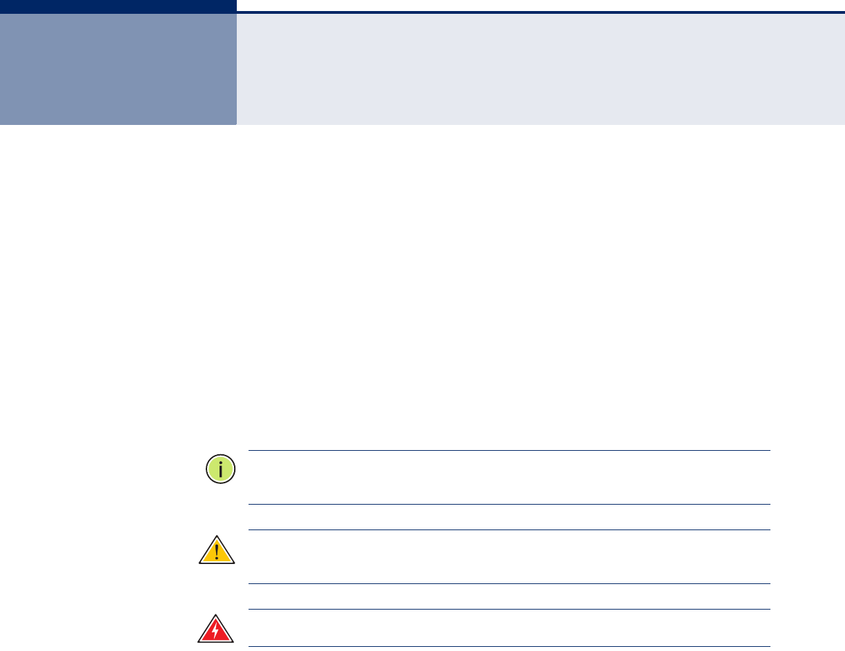
CONVENTIONS The following conventions are used throughout this guide to show
information:
N
OTE
:
Emphasizes important information or calls your attention to related
features or instructions.
C
AUTION
:
Alerts you to a potential hazard that could cause loss of data, or
damage the system or equipment.
W
ARNING
:
Alerts you to a potential hazard that could cause personal injury.
RELATED PUBLICATIONS As part of the CPE’s software, there is an online web-based help that
describes all management related features.
REVISION HISTORY This section summarizes the changes in each revision of this guide.
SEPTEMBER 2009 REVISION
This is the first revision of this guide. It is valid for software version
0.06.01.

– 6 –
CONTENTS
COMPLIANCES 3
IMPORTANT NOTE: FCC Radiation Exposure Statement 3
EC Conformance Declaration 4
ABOUT THIS GUIDE 5
CONTENTS 6
FIGURES 9
TABLES 11
SECTION I GETTING STARTED 12
1INTRODUCTION 13
Key Hardware Features 13
Package Contents 14
Hardware Description 15
Antennas 17
LED Indicators 18
Ethernet Ports 19
VoIP Phone Ports 19
Power Connector 19
Reset Button 19
Cable Connections 19
2INSTALLING THE RG211 22
Location Selection 22
Mounting on a Horizontal Surface 23
Mounting on a Wall 24
Connecting and Powering On 25
3INITIAL CONFIGURATION 26
Connecting to the Login Page 26

C
ONTENTS
– 7 –
Home Page and Main Menu 27
SECTION II WEB CONFIGURATION 28
4SYSTEM SETTINGS 29
System Settings 29
WAN Settings 29
LAN Settings 31
SNTP 32
Ethernet Mode 33
5WIMAX SETTINGS 34
Best BST/AU 34
Frequency Scanning 37
Frequency Scanning Parameters 37
Scanning Table 38
Link Quality Counters 39
Ethernet On-Line Counters 40
Integration Time 42
6SECURITY SETTINGS 44
User Registration 44
CA File 45
7 NAT SETTINGS 46
Network Address Translation 46
Virtual Server 47
Demilitarized Zone (DMZ) 48
8FIREWALL SETTINGS 50
Firewall Settings 50
9MANAGEMENT SETTINGS 52
Resetting the Unit 52
Changing the Access Password 53
Software Versions Control 54
Configuration Control 55
TM and PM Upload Control 56
TR Parameters 57

C
ONTENTS
– 8 –
10 STATUS 60
System Status 60
Show All 60
Licence Type 62
Show Best BS ID 63
Show Radio Parameters 63
Show Registration 64
11 LOGOUT 66
Logging Out 66
SECTION III APPENDICES 68
ATROUBLESHOOTING 69
Diagnosing LED Indicators 69
Before Contacting Technical Support 69
BHARDWARE SPECIFICATIONS 71
CC
ABLES AND PINOUTS 75
Twisted-Pair Cable Assignments 75
10/100BASE-TX Pin Assignments 75
Straight-Through Wiring 76
Crossover Wiring 77
GLOSSARY 78
INDEX 81

– 9 –
FIGURES
Figure 1: Top Panel 15
Figure 2: Rear Panel - RG211 3G 16
Figure 3: Rear Panel - RG211 2.5G 17
Figure 4: LEDs 18
Figure 5: Connecting the RG211 20
Figure 6: Anti-slip Feet 23
Figure 7: Wall Mounting 24
Figure 8: Login Page 26
Figure 9: Home Page 27
Figure 10: WAN Settings - Dynamic 29
Figure 11: WAN Settings - Static 30
Figure 12: LAN Settings 31
Figure 13: SNTP Settings 32
Figure 14: Ethernet Mode 33
Figure 15: Best BST/AU 35
Figure 16: Frequency Scanning Parameters 37
Figure 17: Scanning Table 38
Figure 18: Link Quality Counters 39
Figure 19: Ethernet Counters 40
Figure 20: Integration Time 42
Figure 21: User Registration 44
Figure 22: CA File 45
Figure 23: Network Address Translation 46
Figure 24: Virtual Server 47
Figure 25: DMZ 48
Figure 26: Firewall Settings 50
Figure 27: Reset Unit 52
Figure 28: Change Password 53
Figure 29: SW Version Control 54
Figure 30: Configuration Control 55
Figure 31: TM & PM File Upload Control 56

F
IGURES
– 10 –
Figure 32: TR Parameters 57
Figure 33: Show All 60
Figure 34: License Type 62
Figure 35: Show Best BS ID 63
Figure 36: Show Radio Parameters 63
Figure 37: Show Registration 64
Figure 38: Logout 66
Figure 39: Login 66
Figure 40: RJ-45 Connector 75
Figure 41: Straight Through Wiring 76
Figure 42: Crossover Wiring 77


– 12 –
S
ECTION
I
GETTING STARTED
This section provides an overview of the WiMAX CPE, and introduces some
basic concepts about wireless networking. It also describes the basic
settings required to access the management interface.
This section includes these chapters:
◆“Introduction” on page 13
◆“Installing the RG211” on page 22
◆“Initial Configuration” on page 26

– 13 –
1INTRODUCTION
The RG211 CPE is an indoor WiMAX IEEE 802.16e CPE, that is either
2.3 GHz, 2.5 GHz, 3.5 GHz, or 3.8 GHz, high capacity gateways and WiMAX
Wireless Broadband Access subscriber stations, for a home or small office.
Which CPE you use depends on the frequency band of your service
provider’s WiMAX service. Each system provides network connections that
are always on, supporting immediate access to the Internet and other IP
services at high data rates. The unit provides a gateway function between
a WiMAX service provider and a local Ethernet LAN. The device enables a
service provider to deliver last mile broadband wireless access as an
alternative to wired DSL or cable modems.
Part of an extended and field-proven product portfolio, RG211 CPE is an
integral part of the RG211 family, the latest most technologically advanced
wireless solution for broadband deployment. With capacity of up to 20
Mbps download and 5 Mbps upload speed per unit, the RG211 CPE solution
enables the delivery of powerful wireless broadband services to the
subscriber. RG211 CPE is an out-of-the-box solution with immediate
available local stock enabling virtually instant network expansion and
simplified deployment. RG211 CPE provides a wireless solution for the
subscriber to connect to the internet.
With a range of up to 5 Km and lower equipment and deployment costs,
RG211 CPE enables service providers to wirelessly extend their services to
customers in areas where the cost of cabling is prohibitive to deployment.
Remote residential areas can now benefit from high-speed wireless
Internet access, Web browsing and e-mail, and advanced applications such
as multi-media services.
The RG211 is a plug-and-play device that provides a network interface
through an RJ-45 Ethernet switch port, as well as two RJ-11 Voice over IP
(VoIP) phone ports for telecommunications.
KEY HARDWARE FEATURES
The following table describes the main hardware features of the CPEs.
Table 1: Key Hardware Features
Frequency Band Model Number Description
2.3 RG211-2.3 TBC
2.5 RG211-2.5G-4D2V-2T2R Four 10/100-BASE-TX RJ-45 LAN
ports, and two RJ-11 phone ports.

C
HAPTER
1
| Introduction
Package Contents
– 14 –
The RG211 CPE offers a user-friendly web-based management interface for
the configuration of all the unit’s features. Any PC directly attached to the
unit can access the management interface using a web browser, such as
Internet Explorer (version 6.0 or above) or Firefox (version 1.5 or above).
The initial configuration steps can be made through the web browser
interface using the Setup Wizard. It is recommended to make the initial
changes by connecting a PC directly to one of the RG211’s LAN ports.
PACKAGE CONTENTS
The RG211 package includes:
◆WiMAX RG211 unit with integrated antennas
◆RJ-45 cable
◆AC power adapter
◆Four rubber feet
◆User Guide CD
Inform your dealer if there are any incorrect, missing or damaged parts. If
possible,retain the carton, including the original packing materials. Use
them again to repack the product in case there is a need to return it.
3.5 RG211-3.5G-1D1V One 10/100-BASE-TX RJ45 LAN port,
and one RJ-11 phone port.
3.8 RG211-3.8 TBC
Table 1: Key Hardware Features (Continued)
Frequency Band Model Number Description
C
HAPTER
1
| Introduction
Hardware Description
– 15 –
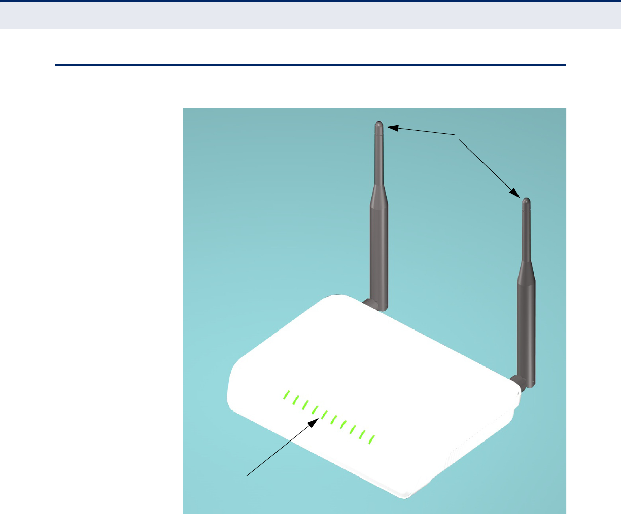
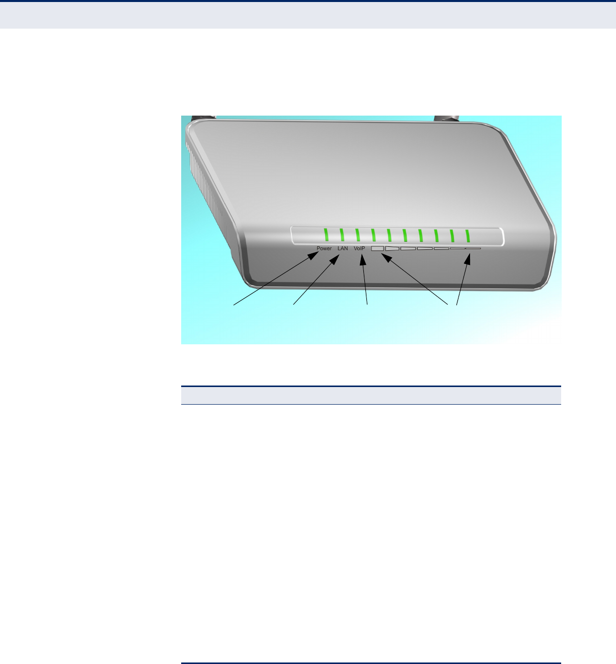
HARDWARE DESCRIPTION
Figure 1: Top Panel
LED Indicators
Antennas
C
HAPTER
1
| Introduction
Hardware Description
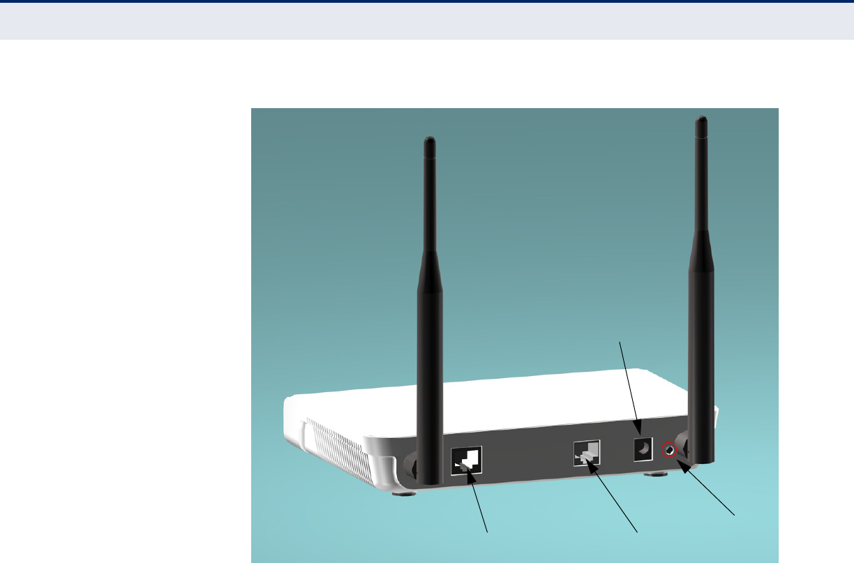
– 16 –
Figure 2: Rear Panel - RG211 3G
DC Power Socket
RJ-45 Port
Reset Button
RJ-11 Phone Port
C
HAPTER
1
| Introduction
Hardware Description
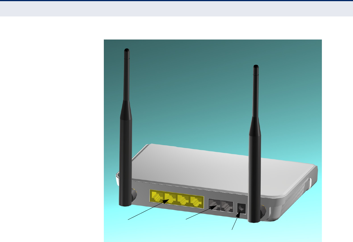
– 17 –
Figure 3: Rear Panel - RG211 2.5G
ANTENNAS Two omnidirectional antennas are included with the RG211 for WiMAX
communications. The omnidirectional antennas transmit and receive
signals in all directions equally.
DC Power Socket
RJ-45 LAN Ports RJ-11 Phone Ports
C
HAPTER
1
| Introduction
Hardware Description
– 18 –
LED INDICATORS The RG211 includes an array of status LED indicators, as described in the
following figure and table.
Figure 4: LEDs
Table 2: LED Behavior
LED Status Description
Power Off The AP has no power.
Yellow The AP is receiving power.
LAN Off Ethernet RJ-45 has no valid link.
Blue Ethernet RJ-45 has a 1000 Mbps link. Blinking indicates
network activity.
Green Ethernet RJ-45 has a 100 Mbps link. Blinking indicates
network activity.
Amber Ethernet RJ-45 has a 10 Mbps link. Blinking indicates
network activity.
VoIP Off The VoIP function is disabled.
Green The VoIP function is enabled.
WiMAX Signal
Strength
(1~7)
All Illuminated The unit is receiving a full WiMAX signal from a
transmitting base station.
Partial
Illumination The unit is receiving a reduced WiMAX signal from a
transmitting base station.
Single
Illumination The unit is receiving a low WiMAX signal from a transmitting
base station.
Power VoIP WiMAX Signal
Strength Indicators
LAN
Link/Activity

C
HAPTER
1
| Introduction
Hardware Description
– 19 –
ETHERNET PORTS The unit has one to four 10/100-BASE-TX RJ-45 ports (depending on
model) that can be attached directly to 10BASE-T/100BASE-TX LAN
segment.
This port supports automatic MDI/MDI-X operation, so you can use
straight-through cables for all network connections to PCs, switches, or
hubs.
The unit appears as an Ethernet node and performs a bridging function by
moving packets from the wired LAN to remote workstations on the wireless
infrastructure.
VOIP PHONE PORTS The RG211 provides a maximum of two RJ-11 telephone ports that connect
directly to a standard (analog) telephone set. This allows a regular
telephone to be used for making VoIP calls over the Internet.
POWER CONNECTOR The unit does not have a power switch. It is powered on when connected to
the AC power adapter, and the power adapter is connected to a power
source. The power adapter automatically adjusts to any voltage between
100~240 volts at 50 or 60 Hz, and supplies 12 volts DC power to the unit.
No voltage range settings are required.
RESET BUTTON This button can be used to restart the RG211.
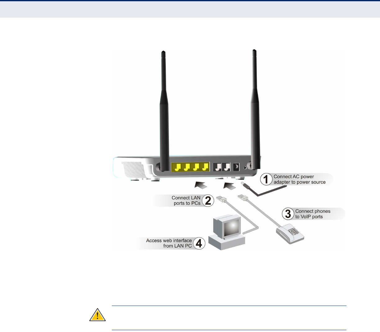
CABLE CONNECTIONS The RG211 is a plug-and-play device, so once it has been connected to
your PC and powered up, it is fully operable.
Functioning as a gateway, the unit routes traffic between a WiMAX network
and PCs or notebooks in the local network.
C
HAPTER
1
| Introduction
Hardware Description
– 20 –
Figure 5: Connecting the RG211
TO CONNECT THE RG211:
1. Power on the RG211 by connecting the AC power adapter and plugging
it into an AC power source.
C
AUTION
:
Use ONLY the power adapter supplied with the RG211. Otherwise,
the product may be damaged.
2. Observe the Indicator LEDs. When you power on the BreezeMAX Si,
verify that the Power LED turns on and that the other LED indicators
start functioning as described under “LED Indicators” on page 18.
3. Connect Category 5 or better Ethernet cables from the RG211’s LAN
ports to the network ports of your PCs. Alternatively, you can connect
the LAN ports to an Ethernet switch or other devices. Make sure the
length of each cable does not exceed 100 meters (328 ft).
4. If your PCs are powered on, the RJ-45 LAN port LED on the RG211
should turn on to indicate valid links.

C
HAPTER
1
| Introduction
Hardware Description
– 21 –
5. Connect one or two standard (analog) telephone sets to the BreezeMAX
Si’s VoIP ports using standard telephone cable with RJ-11 plugs. The
RG211 enables VoIP calls to be made through the unit using a standard
(analog) telephone set connected to a VoIP port, or from PCs or other
network devices connected to the LAN ports. Standard Session
Initiation Protocol (SIP) technology is used to make VoIP calls. You
must access the web interface and configure settings for your SIP
service provider before you can make VoIP calls.
6. Use your PC’s web browser to access the unit’s management interface
and run the Setup Wizard to make any configuration changes.

– 22 –
2INSTALLING THE RG211
This chapter describes how to install the RG211.
LOCATION SELECTION
Choose a proper place for the RG211. In general, the best location is at the
center of your wireless coverage area, within line of sight of all wireless
devices. Try to place the RG211 in a position that can best cover its service
area. For optimum performance, consider these guidelines:
◆Mount the RG211 as high as possible above any obstructions in the
coverage area.
◆Avoid mounting next to or near building support columns or other
obstructions that may cause reduced signal or null zones in parts of the
coverage area.
◆Mount away from any signal absorbing or reflecting structures (such as
those containing metal).
The RG211 can be mounted on any horizontal surface, or a wall.
C
HAPTER
2
| Installing the RG211
Mounting on a Horizontal Surface
– 23 –
MOUNTING ON A HORIZONTAL SURFACE
To keep the RG211 from sliding on the surface, the unit is provided with
four attached rubber feet.
Figure 6: Anti-slip Feet
Rubber Feet
C
HAPTER
2
| Installing the RG211
Mounting on a Wall
– 24 –
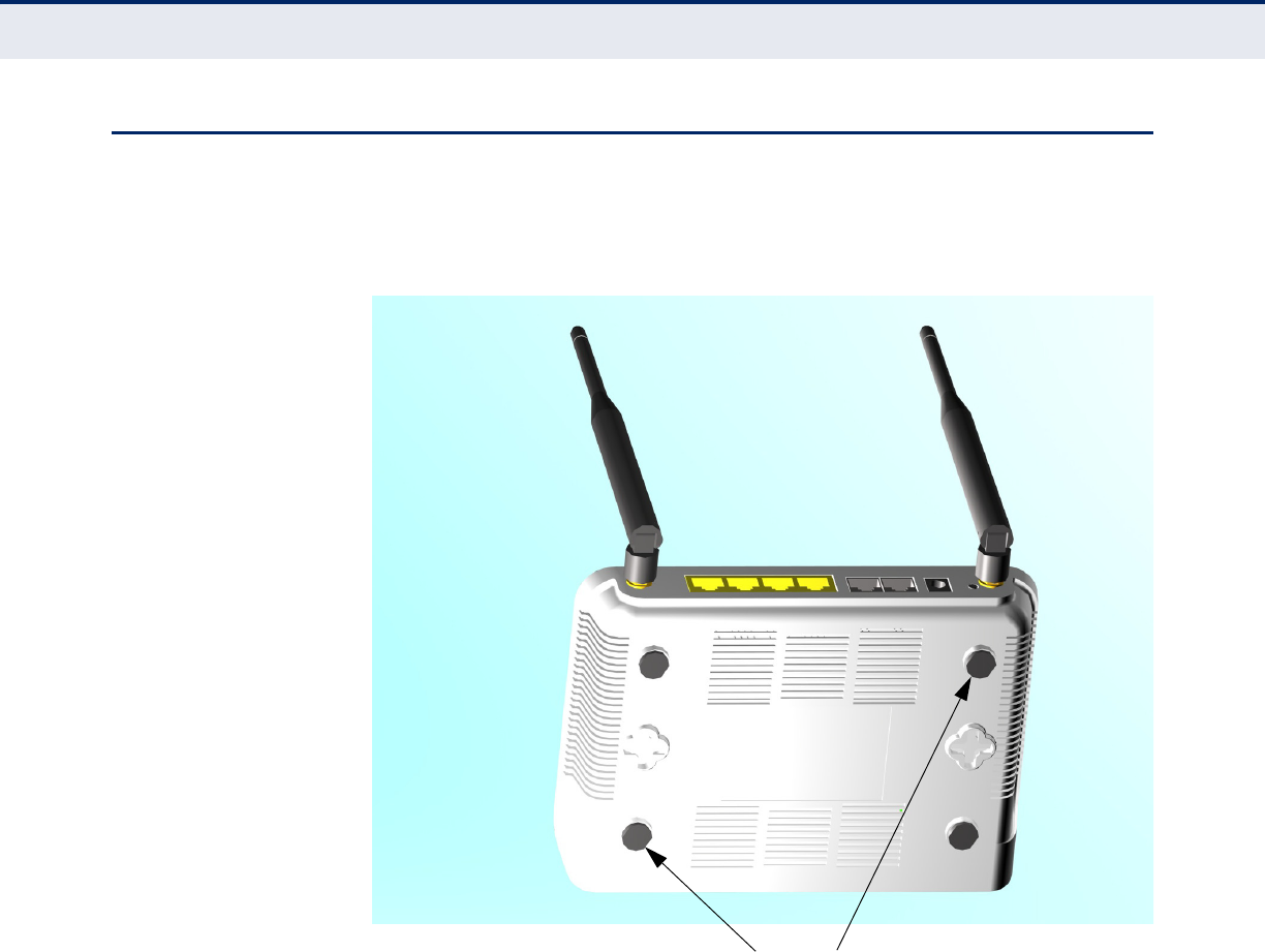
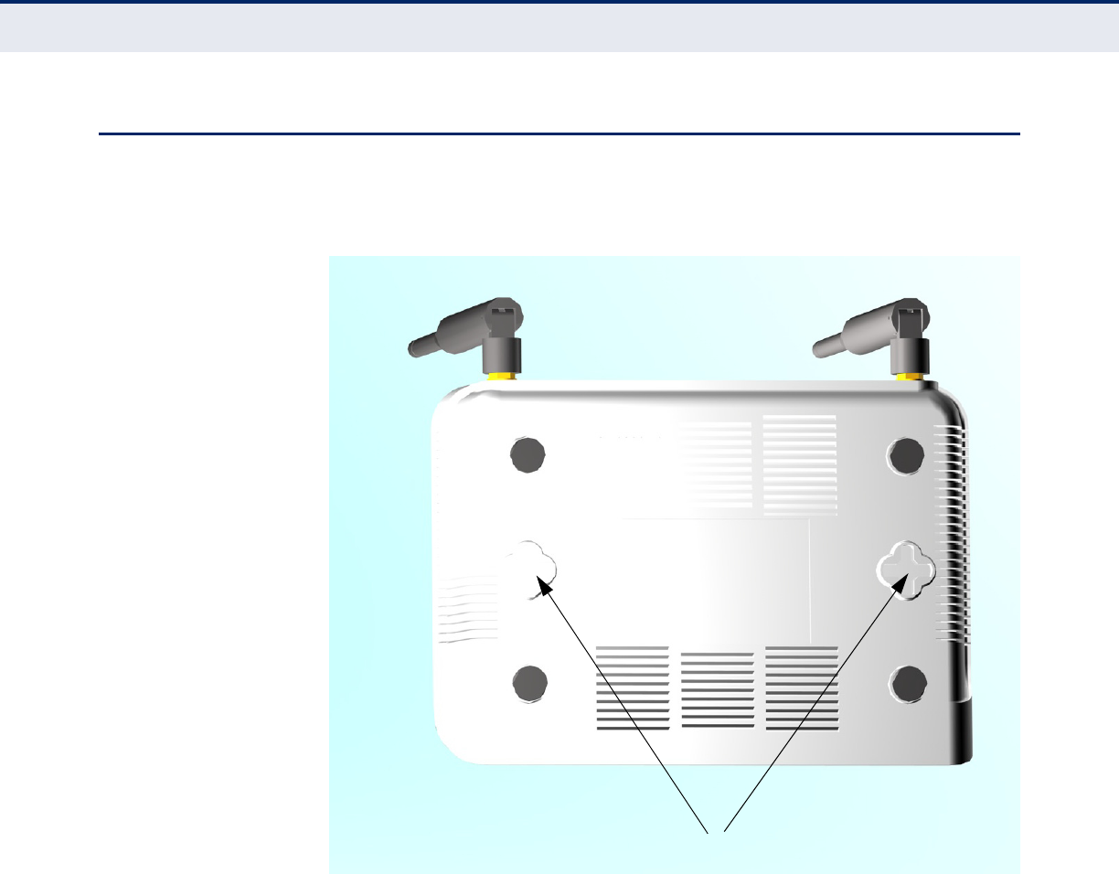
MOUNTING ON A WALL
To mount on a wall follow the instructions below.
Figure 7: Wall Mounting
The RG211 should be mounted only to a wall or wood surface that is at
least 1/2-inch plywood or its equivalent. To mount the RG211 on a wall,
always use its wall-mounting bracket. The RG211 must be mounted with
the RJ-45 cable connector oriented upwards to ensure proper operation.
1. Mark the position of the three screw holes on the wall. For concrete or
brick walls, you will need to drill holes and insert wall plugs for the
screws.
2. Insert the included 20-mm M4 tap screws into the holes, leaving about
2-3 mm clearance from the wall.
3. Line up the three mounting points on the AP with the screws in the wall,
then slide the AP down onto the screws until it is in a secured position.
Mounting Slots
C
HAPTER
2
| Installing the RG211
Connecting and Powering On
– 25 –
CONNECTING AND POWERING ON
Connect the power adapter to the RG211, and the power cord to an AC
power outlet.
C
AUTION
:
Use ONLY the power adapter supplied with this RG211.
Otherwise, the product may be damaged.
1. Observe the Self Test – When you power on the RG211, verify that
the Power indicator turns on, and that the other indicators start
functioning as described under “LED Indicators” on page 18.
2. Connect the Ethernet Cable – The RG211 can be connected to a 10/
100 Mbps Ethernet through a network device such as a hub or a switch.
Connect your network to the RJ-45 port on the back panel with
Category 5E or better UTP Ethernet cable. When the RG211 and the
connected device are powered on, the Ethernet Link LED should turn on
indicating a valid network connection.
N
OTE
:
The RJ-45 ports on the RG211 supports automatic MDI/MDI-X
operation, so you can use straight-through cables for all network
connections to PCs, switches, or hubs.
3. Position the Antennas – Each antenna emits a radiation pattern that
is toroidal (doughnut shaped), with the coverage extending most in the
direction perpendicular to the antenna. Therefore, the antennas should
be oriented so that the radio coverage pattern fills the intended
horizontal space. Also, the antennas should both be positioned along
the same axes, providing the same coverage area. For example, if the
RG211 is mounted on a horizontal surface, all antennas should be
positioned pointing vertically up to provide optimum coverage.
– 26 –
3INITIAL CONFIGURATION
The RG211 offers a user-friendly web-based management interface for the
configuration of all the unit’s features. Any PC directly attached to the unit
can access the management interface using a web browser, such as
Internet Explorer (version 6.0 or above) or Firefox (version 2.0 or above).
CONNECTING TO THE LOGIN PAGE
It is recommended to make initial configuration changes by connecting a
PC directly to the RG211’s LAN port. The RG211 has a default IP address of
192.168.254.251 and a subnet mask of 255.255.255.0. You must set your
PC IP address to be on the same subnet as the RG211 (that is, the PC and
RG211 addresses must both start 192.168.254.x).
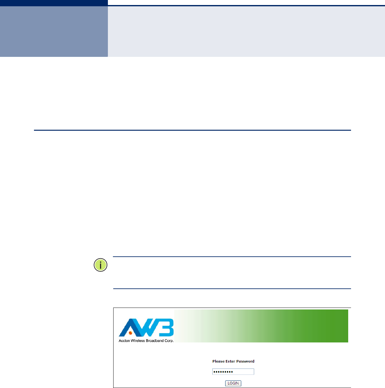
To access the CPE management interface, follow these steps:
1. Use your web browser to connect to the management interface using
the default IP address of 192.168.254.251.
2. Log into the interface by entering the default password “installer,” then
click Login.
N
OTE
:
It is strongly recommended to change the default user name and
password the first time you access the web interface. For information on
changing user names and passwords, See “System Settings” on page 29.
Figure 8: Login Page
C
HAPTER
3
| Initial Configuration
Home Page and Main Menu
– 27 –
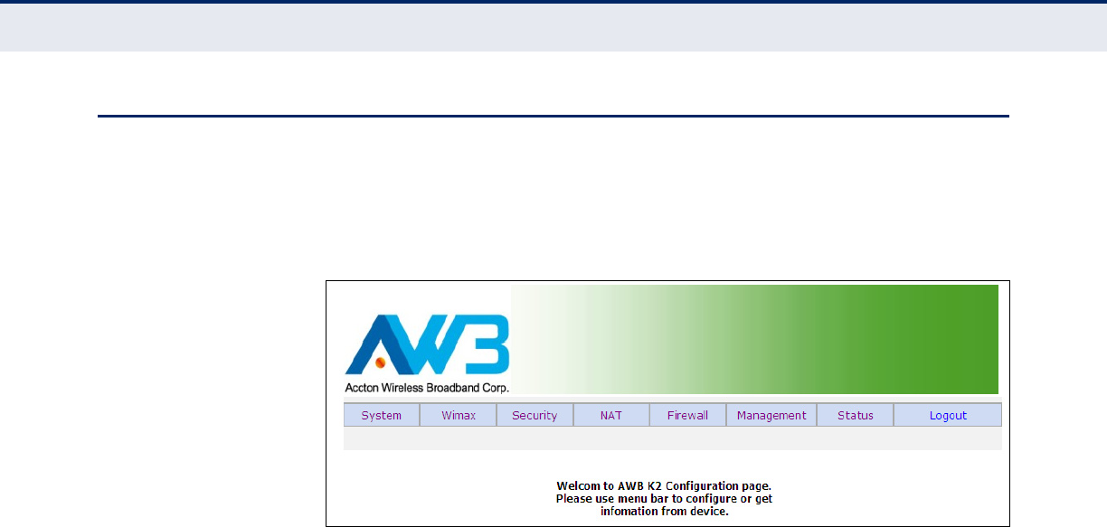
HOME PAGE AND MAIN MENU
After logging in to the web interface, the Home page displays. The Home
page shows some basic settings for the AP, including Country Code and the
management access password.
Figure 9: Home Page
The web interface Main Menu menu provides access to all the configuration
settings available for the CPE.

– 28 –
S
ECTION
II
WEB CONFIGURATION
This section provides details on configuring the CPE using the web browser
interface.
This section includes these chapters:
◆“System Settings” on page 29
◆“WiMAX Settings” on page 34
◆“Security Settings” on page 44
◆“NAT Settings” on page 46
◆“Firewall Settings” on page 50
◆“Management Settings” on page 52
◆“Status” on page 60
◆“Logout” on page 66
– 29 –
4SYSTEM SETTINGS
This chapter describes basic system settings on the CPE. It includes the
following sections:
◆“System Settings” on page 29
■“WAN Settings” on page 29
■“LAN Settings” on page 31
■“SNTP” on page 32
■“Ethernet Mode” on page 33
SYSTEM SETTINGS
The System page configures some basic settings for the CPE, such as the
WAN, LAN SNTP and Ethernet Mode settings.
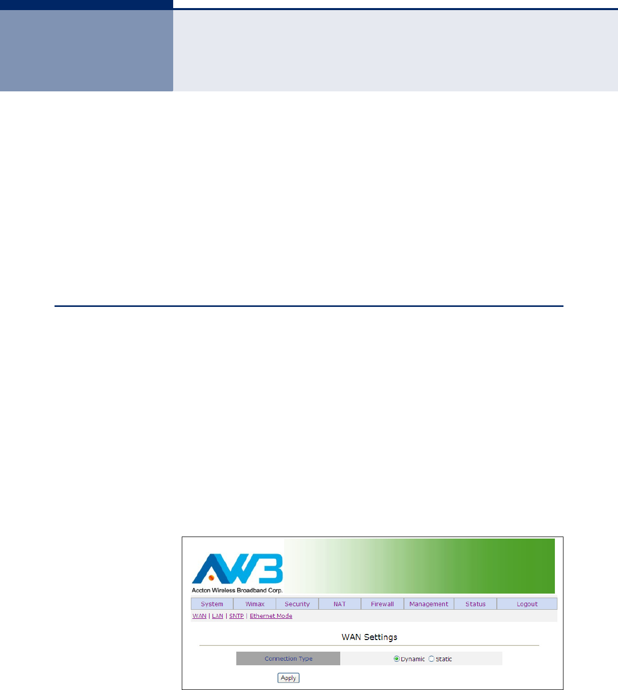
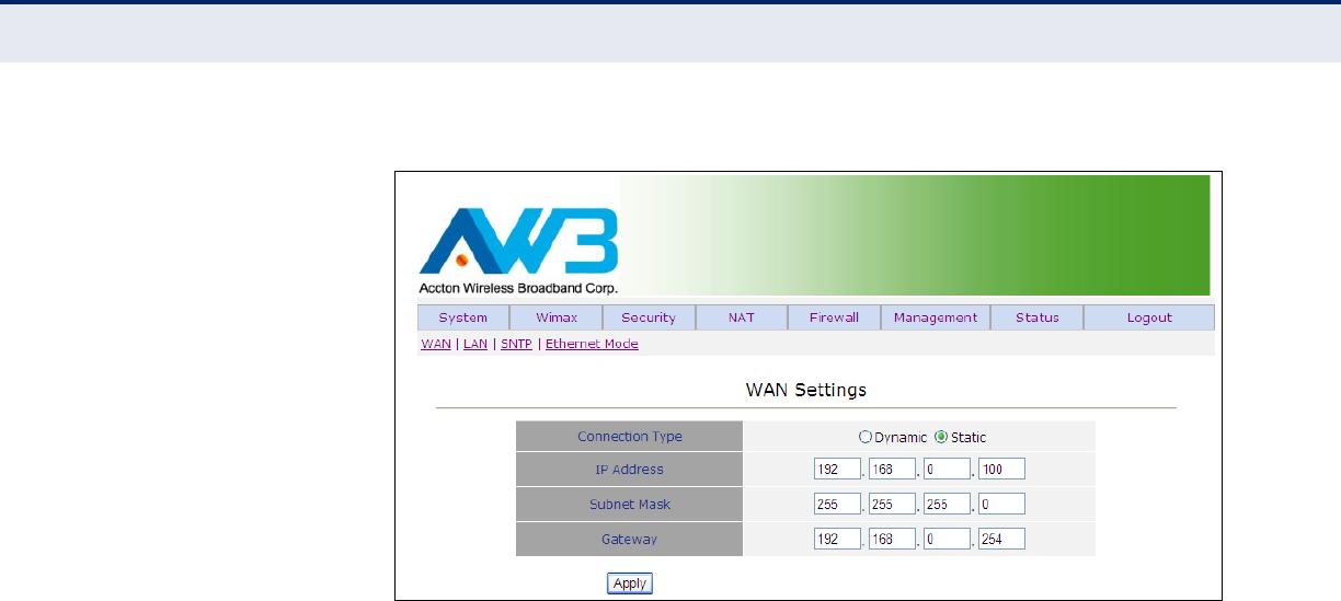
WAN SETTINGS Configuring the CPE with an IP address expands your ability to manage the
CPE. A number of CPE features depend on IP addressing to operate.
You can use the web browser interface to access IP addressing only if the
CPE already has an IP address that is reachable through your network.
By default, the CPE will be not be automatically configured with IP settings
from a Dynamic Host Configuration Protocol (DHCP) server. The default IP
address is 192.168.0.102, subnet mask 255.255.255.0 and a default
gateway of 192.168.0.254.
Figure 10: WAN Settings - Dynamic
C
HAPTER
4
| System Settings
System Settings
– 30 –
Figure 11: WAN Settings - Static
The following items are displayed on these pages:
◆Connection Type — Specifies dynamic or static connection to the
wireless WAN port.
◆IP Address — Specifies an IP address for wireless management of the
CPE. Valid IP addresses consist of four decimal numbers, 0 to 255,
separated by periods. (Default: 192.168.0.102.)
◆Subnet Mask — Indicates the local subnet mask. (Default:
255.255.255.0)
◆Gateway — The default gateway is the IP address of the router for the
CPE, which is used if the requested destination address is not on the
local subnet. (Default: 192.168.0.254)
C
HAPTER
4
| System Settings
System Settings
– 31 –
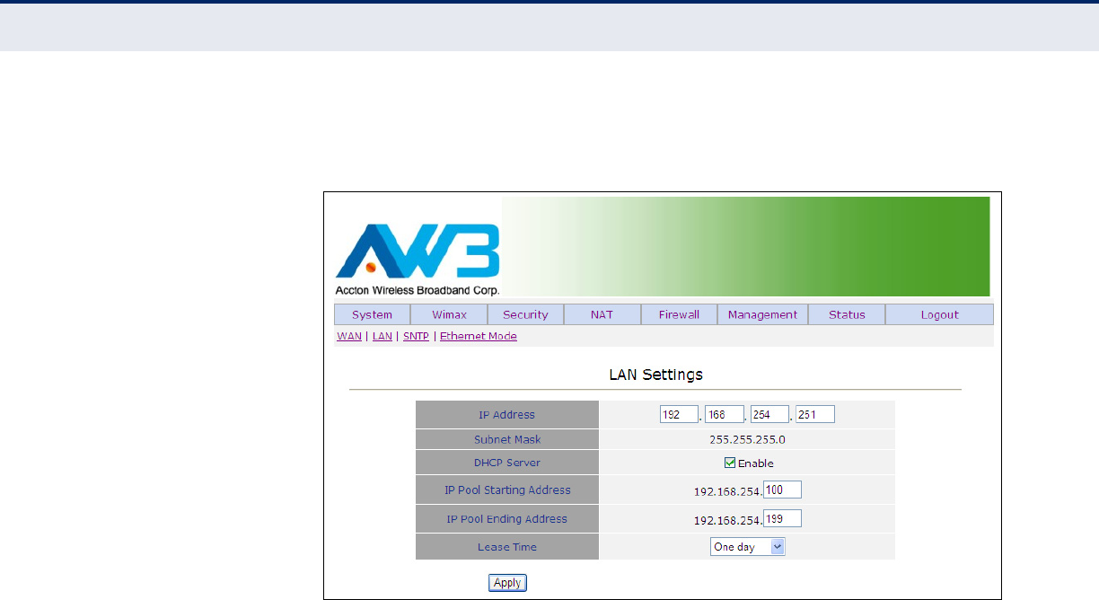
LAN SETTINGS Configuring the CPE with a LAN IP address range enables you to connect
various network devices to the routing capabilities of the RG211.
Figure 12: LAN Settings
The following items are displayed on this page:
◆IP Address — Specifies an IP address for connection to the CPE. Valid
IP addresses consist of four decimal numbers, 0 to 255, separated by
periods. (Default: 192.168.254.251.)
◆Subnet Mask — Indicates the local subnet mask.
(Default: 255.255.255.0)
◆DHCP Server — Enables the DHCP server function.
◆IP Pool Starting Address — Specifies the starting IP address of the
LAN port/s pool.
◆IP Pool Ending Address — Specifies the ending IP address of the LAN
port/s pool.
◆Lease Time — Specifies a lease time for usage of the specified DHCP
Server settings. (Default: One day; Range: Half hour, One hour, Two
hours, Half day, One day, Two days, One week, Two weeks)
C
HAPTER
4
| System Settings
System Settings
– 32 –
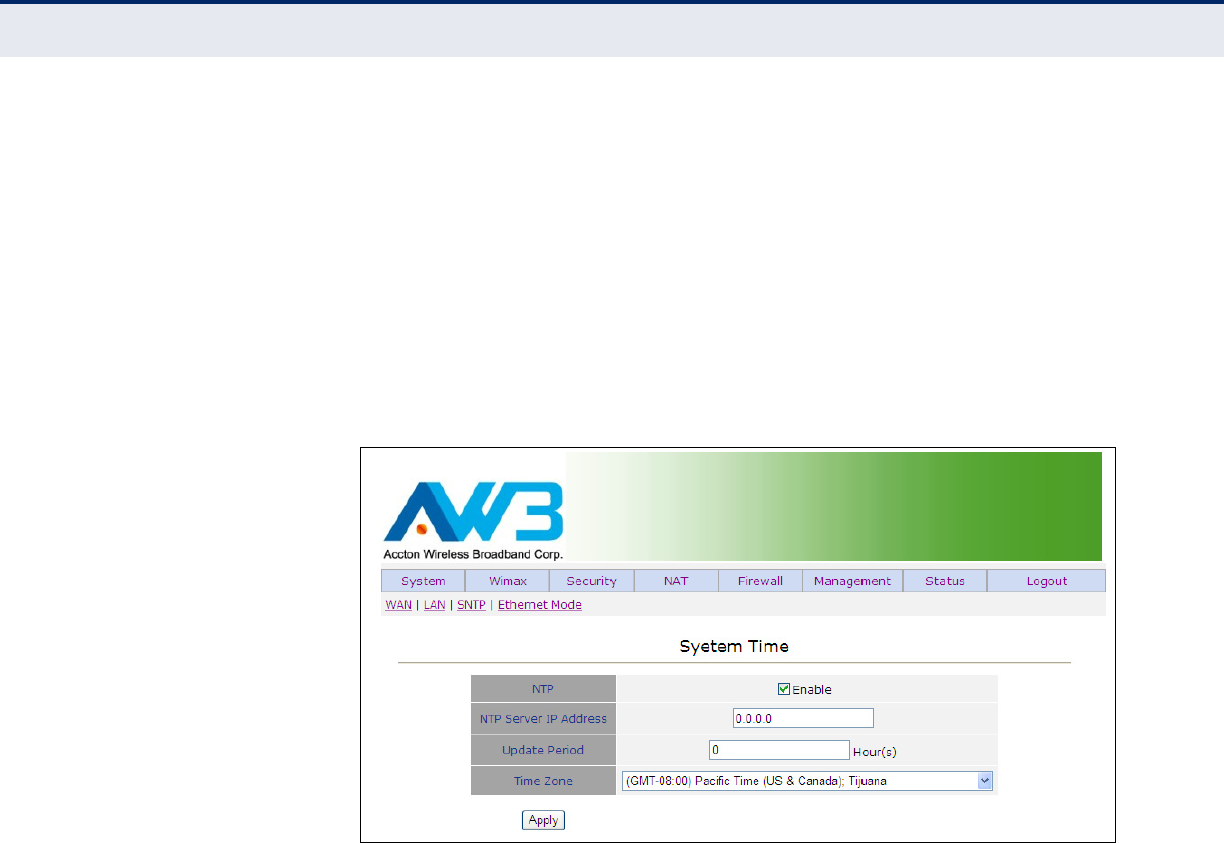
SNTP Simple Network Time Protocol (SNTP) allows the CPE to set its internal
clock based on periodic updates from a time server (SNTP or NTP).
Maintaining an accurate time on the CPE enables the system log to record
meaningful dates and times for event entries. If the clock is not set, the
CPE will only record the time from the factory default set at the last
bootup.
The CPE acts as an SNTP client, periodically sending time synchronization
requests to specific time servers. You can configure up to two time server
IP addresses. The CPE will attempt to poll each server in the configured
sequence.
Figure 13: SNTP Settings
The following items are displayed on this page:
◆NTP — Configures the CPE to operate as an SNTP client.
(Default: Enabled)
◆NTP Server IP Address — The IP address of an SNTP or NTP time
server that the CPE attempts to poll for a time update.
◆Update Period — The interval at which the client sends a time update
request to the SNTP or NTP server.
◆Time Zone — SNTP uses Greenwich Mean Time, or GMT (sometimes
referred to as Coordinated Universal Time, or UTC) based on the time
at the Earth’s prime meridian, zero degrees longitude. To display a time
corresponding to your local time, you must indicate the number of
hours your time zone is located before (east) or after (west) GMT.
Select from the scroll down list the locale you are situated most close
to, for example for New York, select ‘(GMT-05) Eastern Time (US &
Canada)’.
C
HAPTER
4
| System Settings
System Settings
– 33 –
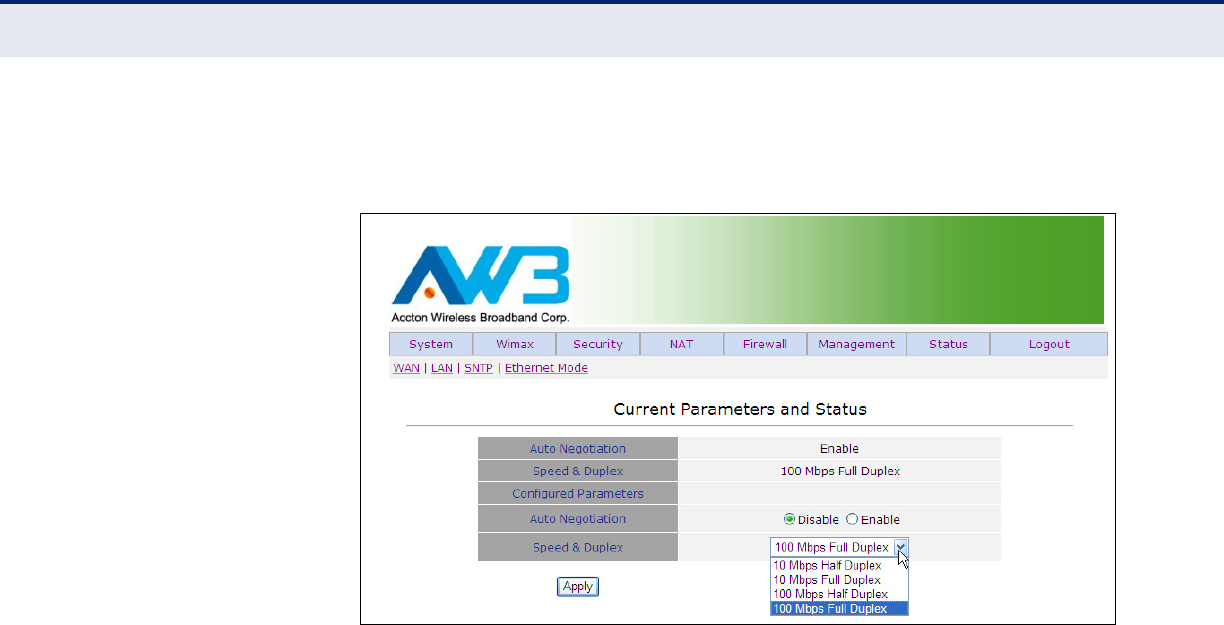
ETHERNET MODE The Ethernet Mode settings displays and configures the mode of the
Ethernet port/s.
Figure 14: Ethernet Mode
The following items are displayed on this page:
◆Auto Negotiation — Displays the auto-negotiation status of the LAN
port/s.
◆Speed & Duplex — Displays the speed and duplex of the LAN port/s.
◆Configured Parameters — this feature is not currently implemented.
◆Auto Negotiation — Enables/disables auto-negotiation. (Default:
Disable)
◆Speed & Duplex — Select from the drop down menu the speed and
duplex of the port/s. (Range: 10 Mbbps Half Duplex, 10 Mbps Full
Duplex, 100 Mbps Half Duplex, 100 Mbps Full Duplex)

– 34 –
5WIMAX SETTINGS
This chapter describes WiMAX management settings on the CPE. It includes
the following sections:
◆“Best BST/AU” on page 34
◆“Frequency Scanning” on page 37
◆“Link Quality Counters” on page 39
◆“Ethernet On-Line Counters” on page 40
◆“Integration Time” on page 42
BEST BST/AU
The BS AU scanning page allows the user to scan for a nearby base station,
specify a frequency, a preferred bandwidth, and frame duration.
The table will display all base stations that match the criteria entered.
N
OTE
:
The access unit will search for the preferred base station first, but
the displayed best base station might not be the preferred base station if it
is unavailable.
C
HAPTER
5
| WiMAX Settings
Best BST/AU
– 35 –
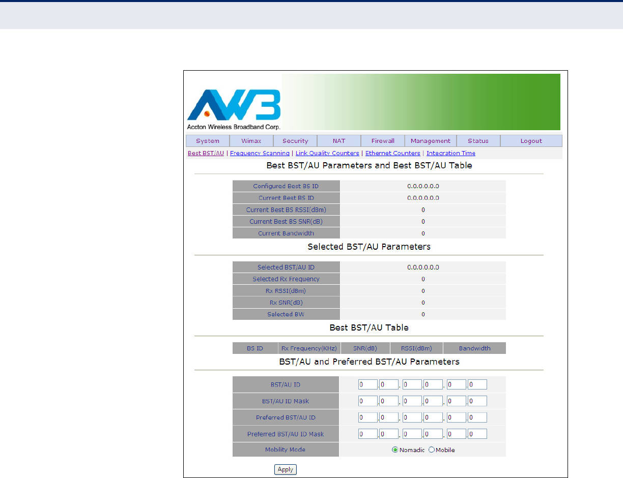
Figure 15: Best BST/AU
BEST BS/AU — The Best BS/AU menu displays information on the base
station identity (BSID), as well as signal strength indication, noise ratio
and bandwidth of the WiMAX connection.
The following items are displayed on Best BST/AU page:
◆Configured Best BS ID — Describes the configured base station
identity, in the form xx.xx.xx.xx.xx.xx.
◆Current Best BS ID — Describes the identity of the best base station,
in the form xx.xx.xx.xx.xx.xx.
◆Current Best BS RSSI (dBm) — Describes the receive signal strength
indicator of the optimal WiMAX link, in decibels per milliwatt.
◆Current Best BS SNR (dB) — Describes the signal to noise ratio of
the optimal WiMAX link, in decibels.

C
HAPTER
5
| WiMAX Settings
Best BST/AU
– 36 –
◆Current Bandwidth — Describes the bandwidth of the optimal WiMAX
link.
SELECTED BST/AU PARAMETERS — The Selected BST/AU Parameters
menu describes the BSID, frequency, signal strength, noise ratio and
identity of the selected base station.
◆Selected BST/AU ID — Describes the configured base station identity,
in the form xx.xx.xx.xx.xx.xx.
◆Frequency — Describes the selected receive signal frequency.
◆Rx RSSI (dBm) — Describes the receive signal strength indicator of
the WiMAX link, in decibels per milliwatt.
◆Rx SNR (dB) — Describes the signal to noise ratio of the WiMAX link,
in decibels.
◆Selected Bandwidth — Describes the bandwidth of the WiMAX link.
BEST BST/AU TABLE — The Best BST/AU Table describes the optimal
base station identity, frequency, signal to noise ratio and bandwidth of the
selected base station.
◆BS ID — Describes the optimal base station identity (BSID).
◆Rx Frequency (MHz) — Describes the optimal base station receive
frequency for the WiMAX link, in megahertz.
◆SNR(dB) — Describes the optimal signal to noise ratio of the WiMAX
link, in decibels.
◆Bandwidth — Describes the optimal bandwidth of the WiMAX link.
BEST BST/AU TABLE – The BST/AU and Preferred BST/AU Parameters
menu describes the user configured base station identity, mask, perferred
base station identity and mask, as well as the mobility mode.
◆BST/AU ID — Allows the user to configure the base station identity.
◆BEST/AU ID MASK — Alllows the user to configure the base station
mask.
◆Preferred BST/AU ID — Allows the user to configure the preferred
base station identity.
◆Preferred BST/AU ID Mask — Allows the user to configure the
preferred base station mask.
◆Mobility Mode — Selects the mobility mode of the WiMAX radio.
(Options: nomadic and mobile)
◆Apply — Applies the specified changes.
C
HAPTER
5
| WiMAX Settings
Frequency Scanning
– 37 –
FREQUENCY SCANNING
Frequency Scanning allows the user to enter frequencies with which to
scan for nearby base stations.
FREQUENCY
SCANNING
PARAMETERS
The Frequency Scanning Parameters menu specifies the frequency,
scanning steps and bandwidth for purposes of scanning for nearby base
stations.
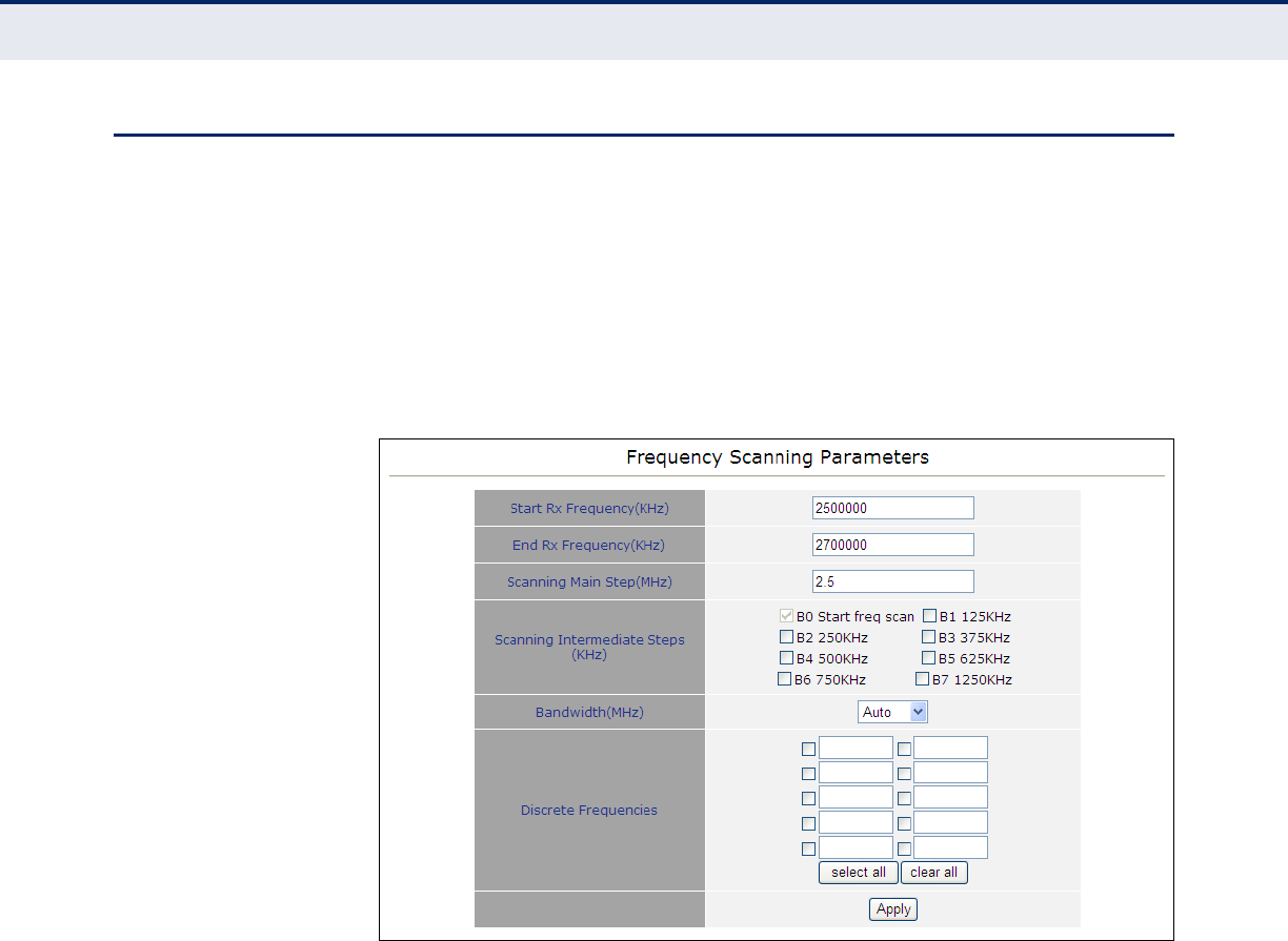
Figure 16: Frequency Scanning Parameters
The following items are displayed on the Frequency Scanning Parameters
page:
◆Start Rx Frequency(MHz) — Specifies the frequency at which to start
scanning, in megahertz.
◆End Rx Frequency(MHz) — Specifies the frequency at which to stop
scanning, in megahertz.
◆Scanning Main Step(KHz) — Specifies the main step in the frequency
scanning process using the formula F(N) = Start Frequency + N*Main
Step, for N = 0,1,2..
◆Scanning Intermediate Steps(KHz) — Specifies the intermediate
step in the scanning process using the formula F(N) = Start Frequency
+ N*(Main Step), Start Frequency + N*(Main Step + Intermediate
Step), for N= 0,1, 2,..
◆Bandwidth(MHz) — Specifies the bandwidth for the scanning process.
C
HAPTER
5
| WiMAX Settings
Frequency Scanning
– 38 –
◆Apply — Saves the specified bandwidth.
◆Discrete Frequencies — Delete a selected discrete frequency.
◆Delete All Discrete Frequencies — Deletes all discrete frequencies.
SCANNING TABLE SCANNING TABLE – The Scanning Table displays all frequencies and
bandwidths scanned by the Extreme CPE.
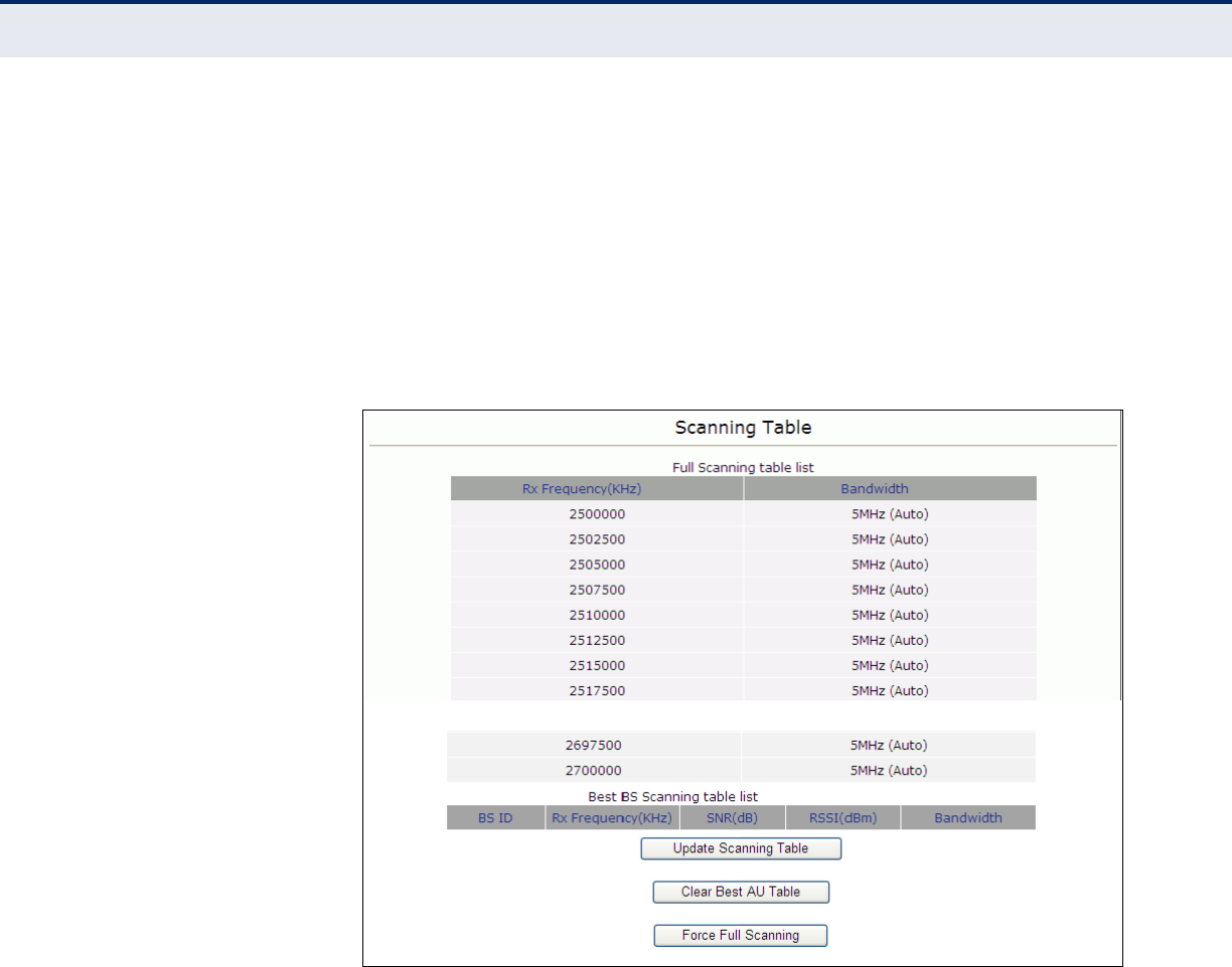
Figure 17: Scanning Table
The following items are displayed on the Scanning Table page:
◆Rx Frequency(MHz) — Describes the receive frequency scanned.
◆Bandwidth — Describes the receive bandwidth scanned.
BEST BS SCANNING TABLE LIST — The Scanning Table List allows the
user to update the scanning table, clear the best AU tabe and force full
scanning.
◆BS ID — Describes the number used to uniquely identify the base
station identity.
◆Rx Frequency(MHz) — Describes the received signal frequency band.
◆SNR(dB) — Describes the signal-to-noise ratio of the received signal.
C
HAPTER
5
| WiMAX Settings
Link Quality Counters
– 39 –
◆Bandwidth — Describes the bandwidth of the received signal.
◆Update Scanning Table — Updates the scanning table.
◆Clear Best AU Table — Clears the table.
◆Force Full Scanning — Forces scanning on all frequencies.
LINK QUALITY COUNTERS
The Link Quality On-Line Display page displays the SNR (signal to noise
ratio), RSSI (receive signal strength indication), and Tx/Rx data levels.
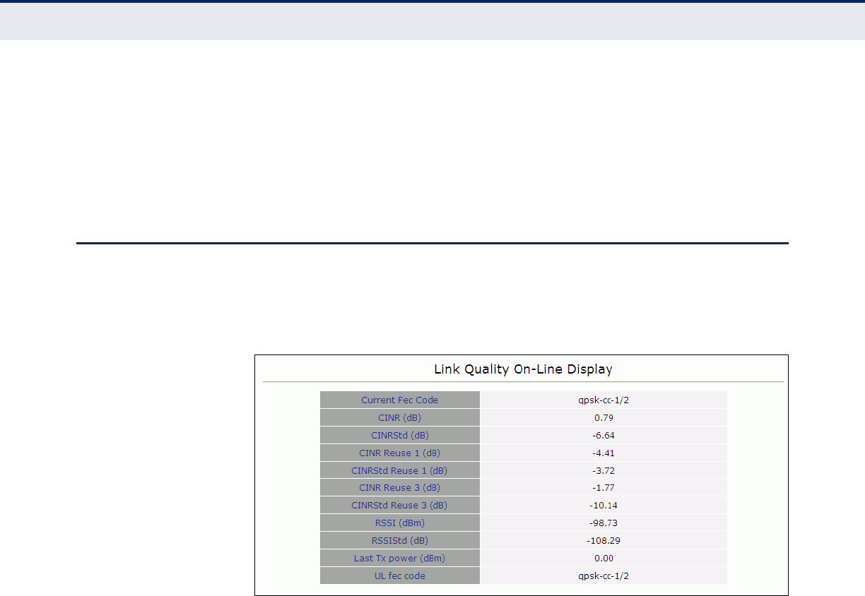
Figure 18: Link Quality Counters
ONLINE LINK QUALITY — The Link Quality On-Line Display table
displays read-only information related to the quality of the link between
the CPE and the base station.
The following items are displayed on the Link Quality On-line Display page:
◆Current Fec Code — Displays the current FEC code.
◆CINR (dB) — Displays the median level of the downlink (DL) Carrier-
to-Interference and Signal-to-Noise (SNR) ratio, measured over a
duration of two seconds. The figure will refresh every two seconds.
◆CINRStd (dB) — Displays the median level of the downlink (DL)
Carrier-to-Interference and Signal-to-Noise (SNR) ratio, measured over
the duration of the link.
◆CINR Reuse 1 (dB) —
◆CINRStd Reuse 1 (dB) —
◆CINR Reuse 3 (dB) —
C
HAPTER
5
| WiMAX Settings
Ethernet On-Line Counters
– 40 –
◆CINRStd Reuse 3 (dB) —
◆RSSI (dBm) — Displays the median level of the downlink Receive
Signal Strength Indicator (RSSI), measured over a duration of two
seconds. The figure will refresh every two seconds.
◆RSSIStd (dB) —
◆Last Tx Power (dBm) — Displays the most recent transmit data rate
of the CPE in Megabits per second, measured over the last two seconds.
The figure will refresh every two seconds.
◆UL FEC Code — Displays the uplink FEC code.
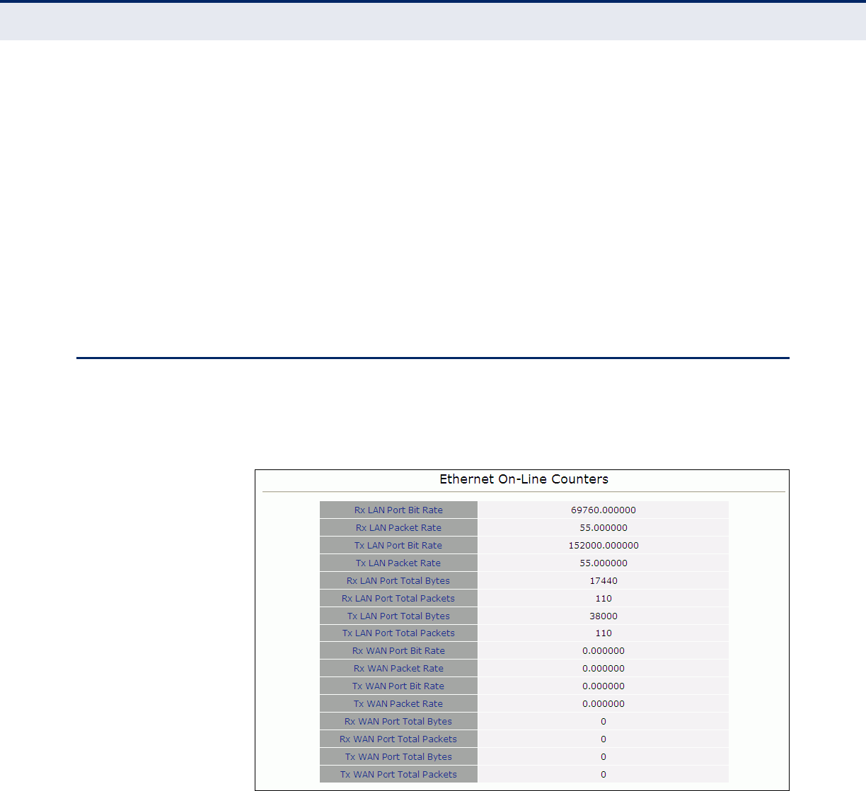
ETHERNET ON-LINE COUNTERS
The Ethernet On-Line Counters page displays RX and Tx levels for the
Ethernet connection.
Figure 19: Ethernet Counters
ETHERNET ON-LINE COUNTERS — The Ethernet On-Line Counters table
describes read-only incremental statistical values of the LAN and WAN
ports.
The following items are displayed on the Ethernet On-Line Counters page:
◆Rx LAN Port Bit Rate — Displays the received bit rate of the Ethernet
LAN port. The figure will refresh every two seconds.

C
HAPTER
5
| WiMAX Settings
Ethernet On-Line Counters
– 41 –
◆Rx LAN Packet Rate — Displays the received packet rate of the
Ethernet LAN port. The figure will refresh every two seconds.
◆Tx LAN Port Bit Rate — Displays the transmitted bit rate of the
Ethernet LAN port. The figure will refresh every two seconds.
◆Tx LAN Packet Rate — Displays the transmitted packet rate of the
Ethernet LAN port. The figure will refresh every two seconds.
◆Rx LAN Port Total Bytes — Displays the received byte rate of the
Ethernet LAN port. The figure will refresh every two seconds.
◆Rx LAN Port Total Packets — Displays the total received packets of
the Ethernet LAN port. The figure will refresh every two seconds.
◆Tx LAN Port Total Bytes — Displays the transmitted byte rate of the
Ethernet LAN port. The figure will refresh every two seconds.
◆Tx LAN Port Total Packets — Displays the total number of packets
transmitted by the Ethernet LAN port. The figure will refresh every two
seconds.
◆Rx WAN Port Bit Rate — Displays the received bit rate of the WiMAX
WAN port. The figure will refresh every two seconds.
◆Rx WAN Packet Rate — Displays the received packet rate of the
WiMAX WAN port. The figure will refresh every two seconds.
◆Tx WAN Port Bit Rate — Displays the transmitted bit rate of the
WiMAX WAN port. The figure will refresh every two seconds.
◆Tx WAN Packet Rate — Displays the transmitted packet rate of the
WiMAX WAN port. The figure will refresh every two seconds.
◆Rx WAN Port Total Bytes — Displays the total bytes received on the
WiMAX WAN port. The figure will refresh every two seconds.
◆Rx WAN Port Total Packets — Displays the total packets received on
the WiMAX WAN port. The figure will refresh every two seconds.
◆Tx WAN Port Total Bytes — Displays the total bytes transmitted by
the WiMAX WAN port. The figure will refresh every two seconds.
◆Tx WAN Port Total Packets — Displays the total number of packets
transmitted by the WiMAX WAN port. The figure will refresh every two
seconds.
C
HAPTER
5
| WiMAX Settings
Integration Time
– 42 –
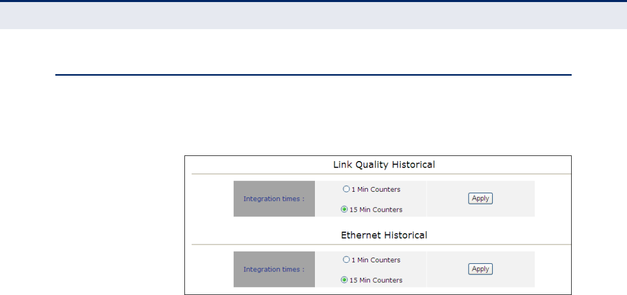
INTEGRATION TIME
The Integration Time page allows you to set the frequency with which the
CPE will monitor traffic statistics on both the WiMAX link and Ethernet link.
Figure 20: Integration Time
The following items are displayed on the Integration Time page:
LINK QUALITY HISTORICAL — The Link Quality Historical menu allows
the user to define a time period for monitoring the WiMAX WAN port link.
◆1 Min Counters — Sets the counter to a duration of one minute.
◆15 Min Counters — Sets the counter to a duration of fifteen minutes.
◆Apply — Applies the chosen setting.
ETHERNET HISTORICAL — The Ethernet Historical menu allows the user
to define a time period for monitoring the Ethernet LAN port link.
◆1 Min Counters — Sets the counter to a duration of one minute.
◆15 Min Counters — Sets the counter to a duration of fifteen minutes.
◆Apply — Applies the chosen setting.

C
HAPTER
5
| WiMAX Settings
Integration Time
– 43 –
– 44 –
6SECURITY SETTINGS
The Security menu enables the user to enter station information about for
the CPE, such as user name, password, country of operation and
organisation. It also enables the user to select the authentication method
used to authenticate the CPE with the base station. It contains the
following sections:
■“User Registration” on page 44
■“CA File” on page 45
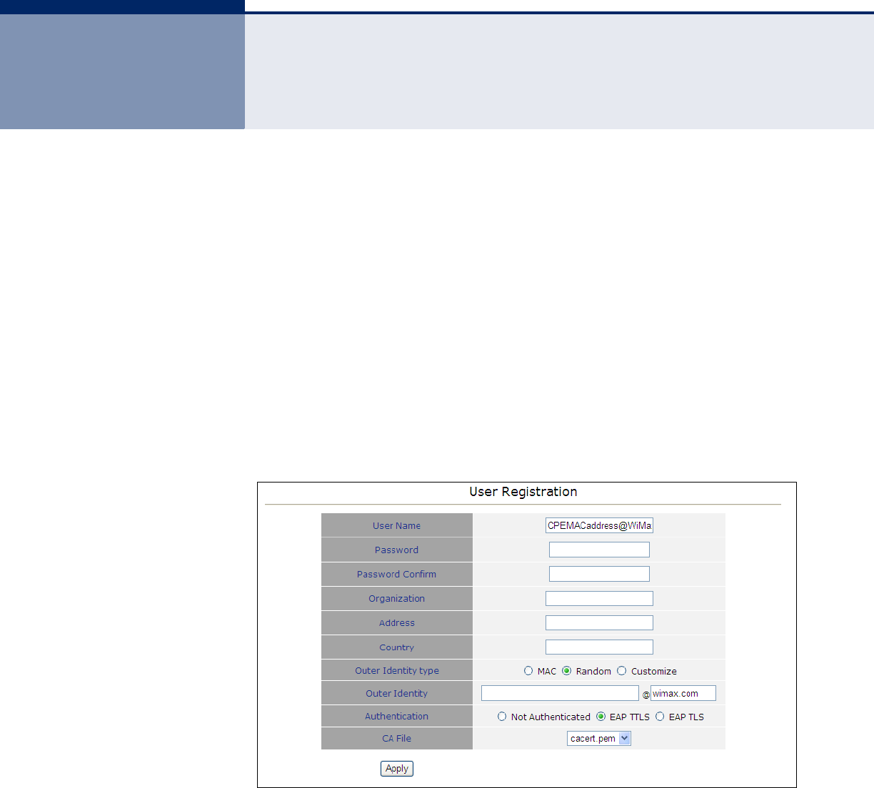
USER REGISTRATION The User Registration page allows the user to define registration
parameters such as configured user name, password, organisation and the
country of operation of the CPE. It also allows the user to select the
authentication method.
Figure 21: User Registration
USER REISTRATION — The User Registration menu allows the user to
enter information on the authentication parameters required to support
provisioning on the unit.
The following items are displayed on the User Registration page:
◆User Name — Allows the user to enter a user name for the unit, in the
form someone@WiMAX.com.
C
HAPTER
6
| Security Settings
– 45 –
◆Password — Allows the user to set a password for registration
purposes.
◆Password Confirm — Prompts the user to re-enter the password.
◆Organization — Enter the WiMAX subscriber name.
◆Address — Enter the contact information for the WiMAX subscriber.
◆Country — Enter the country of operation.
◆Authentication — Allows the user to describe the method of
authentication being used to secure the WiMAX connection. (Options:
none; EAP TTLS; EAP TLS)
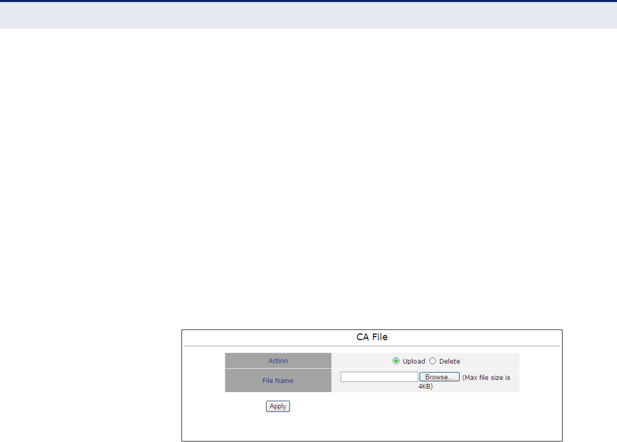
CA FILE The CA File is the root file used in certificate-based authentication. This file
is used by the CPE to identify the ACS. Note that because this
authentication process uses SSL/TLS, the ACS URL attribute on this page
must be specified as an HTTPS URL.
Figure 22: CA File
The following items are displayed on the CA File page:
◆Action — Specifies to upload or delete the current CA file.
◆File Name — Click browse to locate the CA file on the local PC.
– 46 –
7NAT SETTINGS
This chapter describes NAT settings on the CPE. It includes the following
sections:
◆“Network Address Translation” on page 46
◆“Virtual Server” on page 47
◆“Demilitarized Zone (DMZ)” on page 48
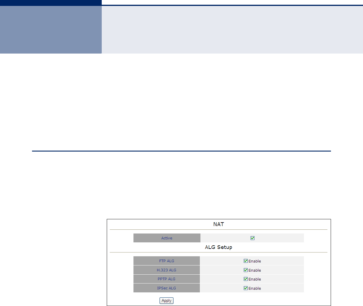
NETWORK ADDRESS TRANSLATION
Network Address Translation (NAT) is a method of mapping between a
single global address on the WAN interface to multiple local addresses on
the LAN interface. For the Gateway, the internal (local) IP addresses are
those assigned to PCs or other network devices by the DHCP server, and
the external IP address is the single address assigned to the WAN port.
Figure 23: Network Address Translation
The following items are displayed on the NAT page:
◆Active — Activates NAT.
ALG Setup — This page is used to enable or disable customized
Application Layer Gateway (ALG) traversal filters for SIP, H323, IRC, PPTP,
SNMP, and TFTP applications.
◆FTP ALG — File Transfer Protocol.
◆H.323 ALG — ITU-T standard that defines protocols used to provide
audio-visual communication sessions on any packet-based network. It
C
HAPTER
7
| NAT Settings
Virtual Server
– 47 –
is widely deployed by service providers to support both voice and video
services over IP networks.
◆PPTP ALG — Point-to-Point Tunneling Protocol is a method for
implementing virtual private networks.
◆IPSec ALG — Internet Protocol Security is a protocol suite for securing
Internet Protocol (IP) communications by authenticating and
encrypting each IP packet of a data stream.
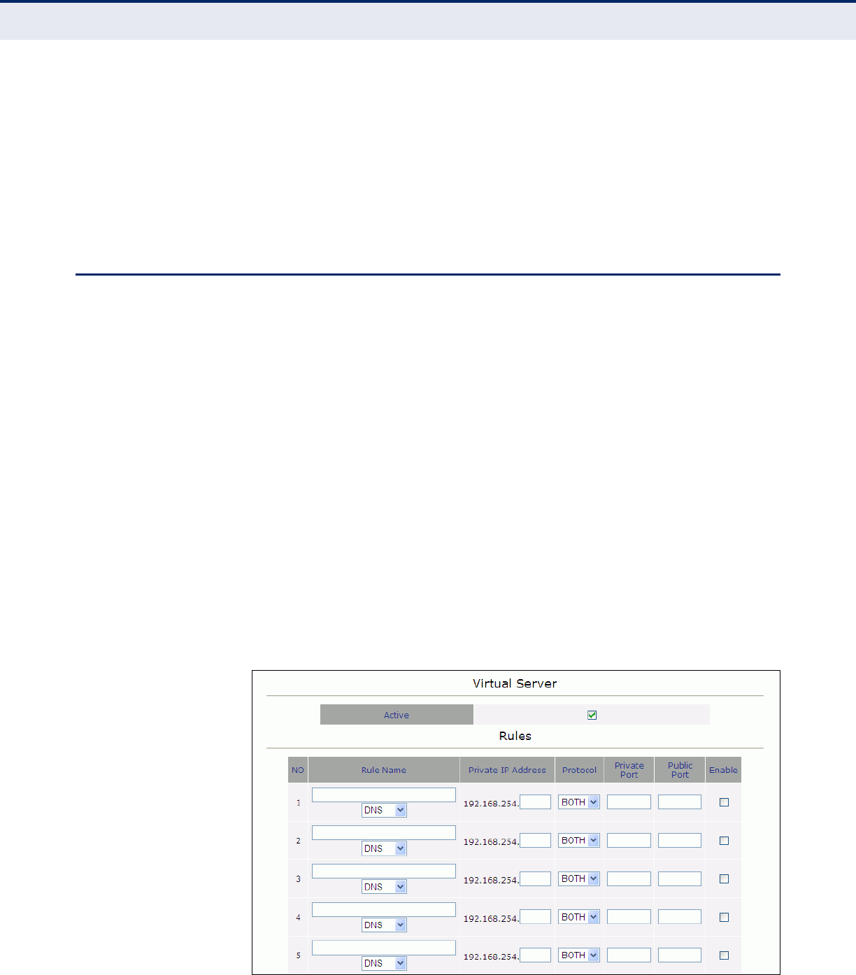
VIRTUAL SERVER
If you configure the CPE as a virtual server, remote users accessing
services such as web sites or FTP servers on your local network through
public IP addresses can be automatically redirected to local servers
configured with private IP addresses. In other words, depending on the
requested service (designated by the TCP/UDP port number), the CPE
redirects the external service request to the appropriate server (located at
an internal IP address). This secures your network from direct attack by
hackers, and provides more flexible management by allowing you to
change internal IP addresses without affecting outside access to local
network services.
For example, if you set Type/Public Port to TCP/80 (HTTP or web) and the
Private IP/Port to 192.168.2.2/80, then all HTTP requests from outside
users will be transferred to 192.168.2.2 on port 80. Therefore, by just
entering the IP address provided by the ISP, Internet users can access the
service they need at the local address to which you redirect them.
The more common TCP service port numbers include: HTTP: 80, FTP: 21,
Telnet: 23, and POP3: 110.
Figure 24: Virtual Server
C
HAPTER
7
| NAT Settings
Demilitarized Zone (DMZ)
– 48 –
The following items are displayed on the Virtual Server page:
◆Active — Activates the virtual server.
◆Rule Name — From the drop down menu select the protocol to use.
◆Private IP Address — The IP address of a server on the local network.
The specified address must be in the same subnet as the CPE and its
DHCP server address pool.
◆Protocol — Specifies the port type, TCP or UDP. (Default: TCP)
◆Private Port — Specifies the local LAN TCP/UDP port number. (Range:
1-65535)
◆Public Port — Specifies the WAN port number.
◆Enable — Enables the rule.
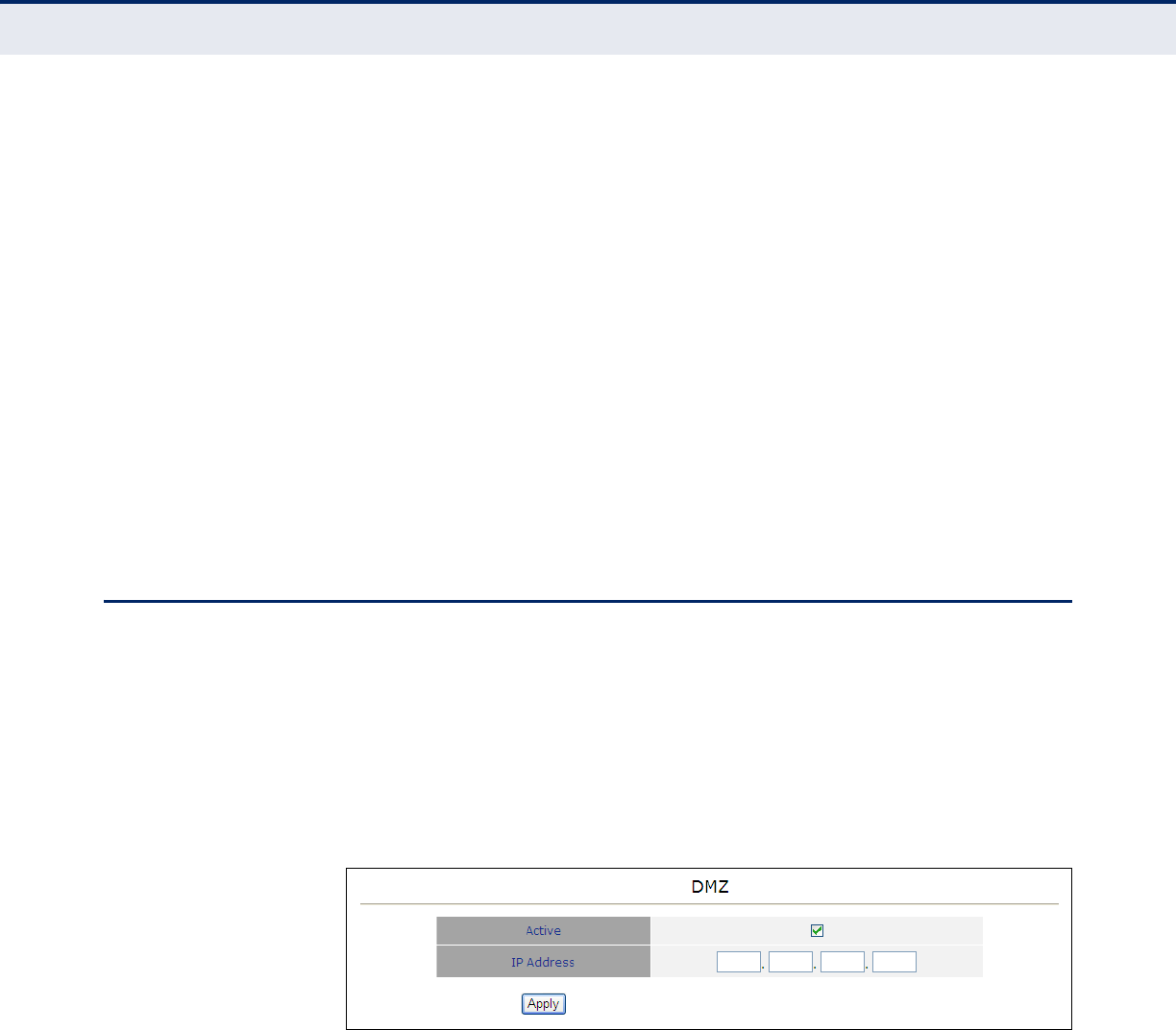
DEMILITARIZED ZONE (DMZ)
This page is used to allow a specified host on the local network to access
the Internet without any firewall protection. Some Internet applications,
such as interactive games or videoconferencing, may not function properly
behind the CPE’s firewall. By specifying a Demilitarized Zone (DMZ) host,
the PC's TCP ports are completely exposed to the Internet, allowing
unrestricted two-way communications. The host PC should be assigned a
static IP address and this address configured as the DMZ host IP.
Figure 25: DMZ
The following items are displayed on the DMZ page:
◆Active — Actives the DMZ service.
◆IP Address — Specify an IP address to allow access to.

C
HAPTER
7
| NAT Settings
Demilitarized Zone (DMZ)
– 49 –
– 50 –
8FIREWALL SETTINGS
This chapter describes firewall settings on the CPE. It includes the following
section:
◆“Firewall Settings” on page 50
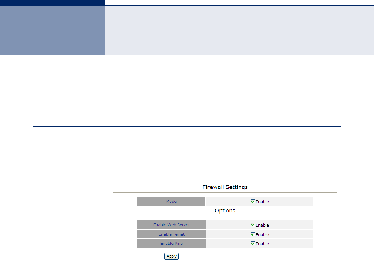
FIREWALL SETTINGS
The CPE provides extensive firewall protection by restricting connection
parameters to limit the risk of intrusion and defending against a wide array
of common hacker attacks.
Figure 26: Firewall Settings
The following items are displayed on the Firewall page:
◆Mode — Enables firewall protection. (Default: Enabled)
◆Enable Web Server — Enables web server protection. (Default:
Enabled)
◆Enable Telenet — Enables Telnet protect. (Default: Enabled)
◆Enable Ping — Enables ping protection. (Default: Enabled)

C
HAPTER
8
| Firewall Settings
Firewall Settings
– 51 –
– 52 –
9MANAGEMENT SETTINGS
This chapter describes Management settings on the CPE. It includes the
following section:
◆“Resetting the Unit” on page 52
◆“Changing the Access Password” on page 53
◆“Software Versions Control” on page 54
◆“Configuration Control” on page 55
◆“TM and PM Upload Control” on page 56
◆“TR Parameters” on page 57
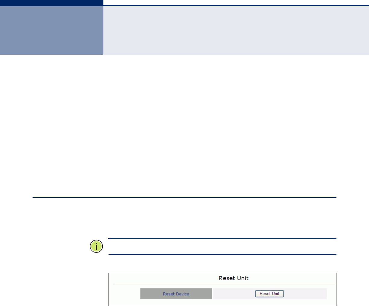
RESETTING THE UNIT
The Reset page allows you to reset the CPE for configuration changes to
take effect.
N
OTE
:
Reseting the unit does not restore factory defaults.
Figure 27: Reset Unit
The following items are displayed on the Reset Unit page:
◆Reset Unit — Click ‘Reset Unit’ to reboot the CPE.
C
HAPTER
9
| Management Settings
Changing the Access Password
– 53 –
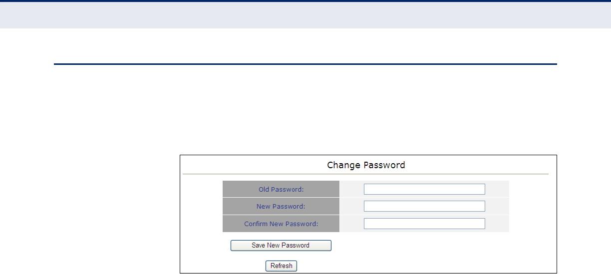
CHANGING THE ACCESS PASSWORD
The Change Password page enables you to create a new password for
access to the CPE. It is advisable to change the factory default password
upon receipt of your CPE device.
Figure 28: Change Password
The following items are displayed on the Change Password page:
◆Old Password — Prompts you to enter your current password.
◆New Password — Prompts you to enter a new password. (Length: 1-
20 characters, cannot include the characters ‘<>?:;,.’”{[}]/\|,’ and is
case sentivitive.
◆Confirm New Password — Prompts you to re-enter the new
password.
◆Save New Password — Clicking ‘Save New Password’ saves the new
password and deletes the old password.
◆Refresh — Clicking ‘Refresh’ clears all information boxes.
C
HAPTER
9
| Management Settings
Software Versions Control
– 54 –
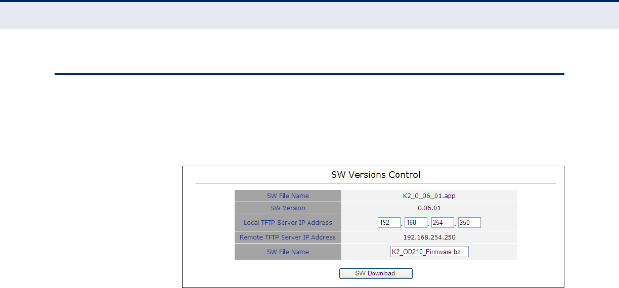
SOFTWARE VERSIONS CONTROL
The Software Version Control page allows you to download new runtime
software for the CPE, run a backup runtime image (or shadow), reset the
device and select the current running configuration file.
Figure 29: SW Version Control
The following items are displayed on the SW Versions Control page:
SW VERSIONS CONTROL — Enables uploading and setting of main
software versions.
◆SW File Name — Describes the file name of the currently loaded
software.
◆SW Version — Describes the version of software currently in use.
◆Local TFTP Server IP Address — Allows the user to enter the IP
address of the TFTP server from which to download code to the unit.
◆Remote TFTP Server IP Address — Non-configurable preset remote
TFTP server address.
◆SW File Name — Allows the user to enter the file name of the software
file to be downloaded to the unit.
◆SW Download — Click ‘SW Download’ to download user specified
software to the unit from the TFTP IP address. The image downloaded
will overwrite the current shadow image.
C
HAPTER
9
| Management Settings
Configuration Control
– 55 –
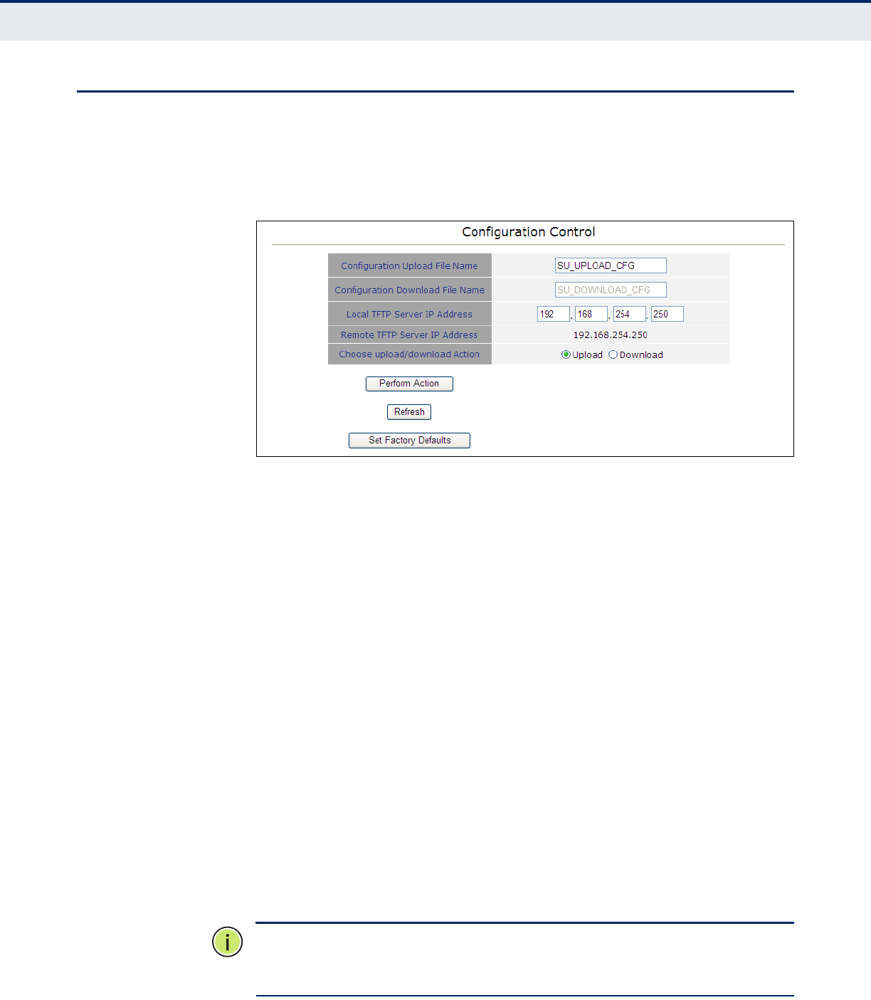
CONFIGURATION CONTROL
The Configuration Control page allows you to specify an IP address from
which to upload or download a running configuration file. It also allows you
to restore the factory default TFTP server address.
Figure 30: Configuration Control
The following items are displayed on the Configuration Control page:
CONFIGURATION CONTROL — Use the configuration control page to
transfer running configuration files.
◆Configuration Upload File Name — Allows the user to specify the
configuration upload file name for copying to the TFTP server.
◆Configuration Download File Name — Allows the user to specify the
configuration download file name for downloading from the TFTP server.
◆Local TFTP Server IP Address — Specifies a TFTP server IP address
for upload/download.
◆Chose upload/download — Selects to either upload to, or download
from the specified TFTP server.
◆Perform Action — Performs the selected upload or download
procedure.
◆Refresh — Reloads the page and the parameters associated with it.
◆Set Factory Defaults — Resets the factory default configuration file
path settings from the TFTP server to the Extreme CPE.
N
OTE
:
Selecting this option does not perform a factory reset. It simply
makes available the TFTP IP path of the default factory configuration file
settings to the unit. Selecting ‘Action’ will implement the file settings.
C
HAPTER
9
| Management Settings
TM and PM Upload Control
– 56 –
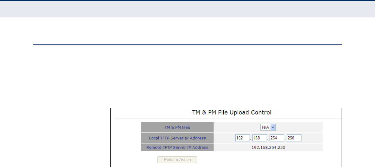
TM AND PM UPLOAD CONTROL
The TM (Traffic Monitoring) & PM (Performance Monitoring) File Upload
Control page enables the user to define parameters related to uploading
the TM & PM files where link quality data is stored, to the TFTP server
directory and to initiate the upload operation.
Figure 31: TM & PM File Upload Control
The following items are displayed on the TM & PM File Upload Control page:
TM & PM FILE UPLOAD CONTROL — Traffic and performance monitoring
allow for a variety of statistical data to be collected about the Extreme CPE
and its WiMAX link.
◆TM & PM Files — Specifies the available TM and PM files from the drop
down menu for uploading to the TFTP server.
◆Local TFTP Server IP Address — Specifies a local TFTP server IP
address from which to upload the TM and PM files.
◆Perform Action — Clicking ‘Perform Action’ initiates the upload
procedure.
C
HAPTER
9
| Management Settings
TR Parameters
– 57 –
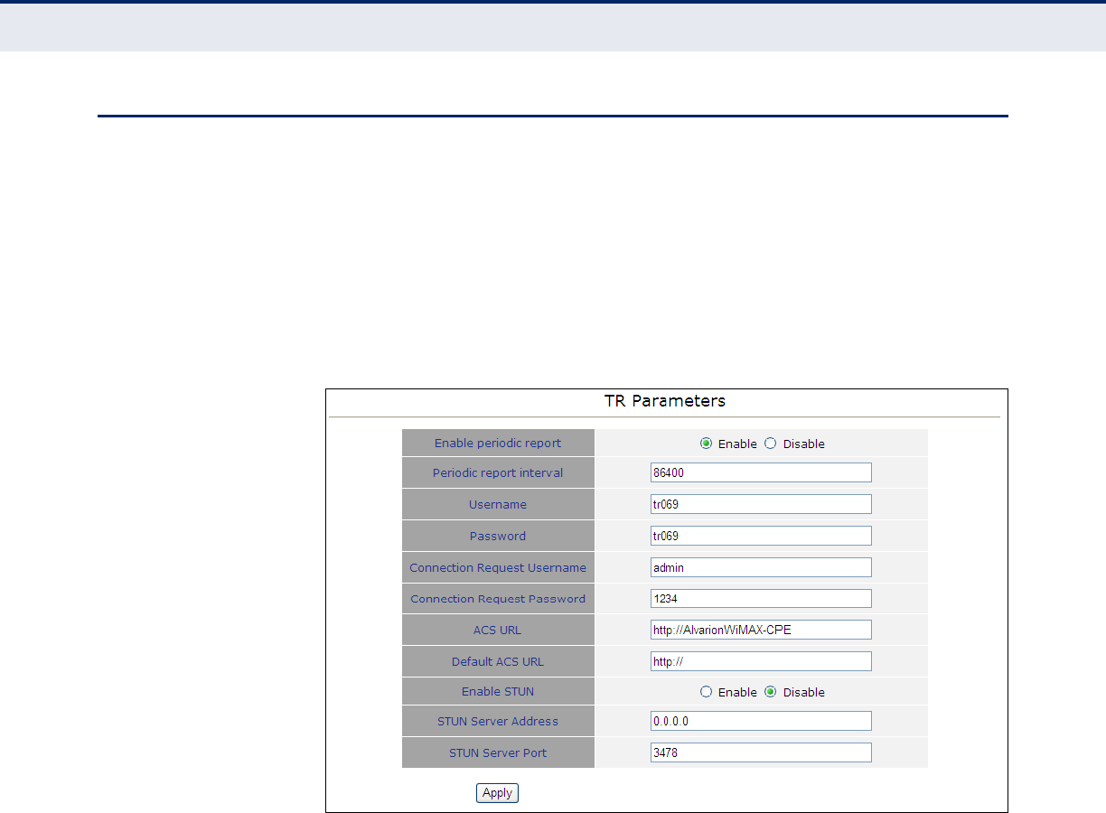
TR PARAMETERS
The Technical Report 069 (TR069) protocol defines a specification for
remote management of CPE devices. The protocol uses HTTP for two-way
communication between the CPE device and an Auto Configuration Server
(ACS), allowing service providers to provide CPE configuration, software
upgrades, and other service functions for end-users.
The CPE’s TR-069 parameters need to be defined to allow communication
with the remote ACS.
Figure 32: TR Parameters
The following items are displayed on the TR Parameters page:
◆TR069 — Enables/disables TR-069 support. (Default: Enabled)
◆Periodic Inform Interval — Time interval in seconds to send Inform
RPC.
◆Username — Enter the user name that the CPE should use when
connecting to the ACS.
◆Password — Enter the password that the ADSL Router should use
when connecting to the ACS.
◆Connection Request Username — The user name the remote ACS
should use when connecting to this device.
◆Connection Request Password — The password the remote ACS
should use when connecting to this device.

C
HAPTER
9
| Management Settings
TR Parameters
– 58 –
◆ACS URL — Specifies the URL required for the CPE to connect to the
ACS.
◆Default ACS URL — The default URL used for the CPE to connect to
the ACS.
◆Enable STUN — Enables the STUN facility. (Default: Disabled)
◆STUN Server Address — Specify the STUN server IP address.
◆STUN Server Port — Specify the port to be used for communication
between the CPE and the STUN server.

C
HAPTER
9
| Management Settings
TR Parameters
– 59 –
– 60 –
10 STATUS
This chapter describes Status settings on the CPE. It includes the following
section:
◆“System Status” on page 60
SYSTEM STATUS
The Status page is a display-only menu of non-configurable parameters for
Unit Control, Registration, Base Station Identification (BSID), Radio, Multi
rate, Adaptative Transmission Power Control (ATPC) and Service. To
configure the parameters associated with each show menu item refer to
the sections listed in the main menu.
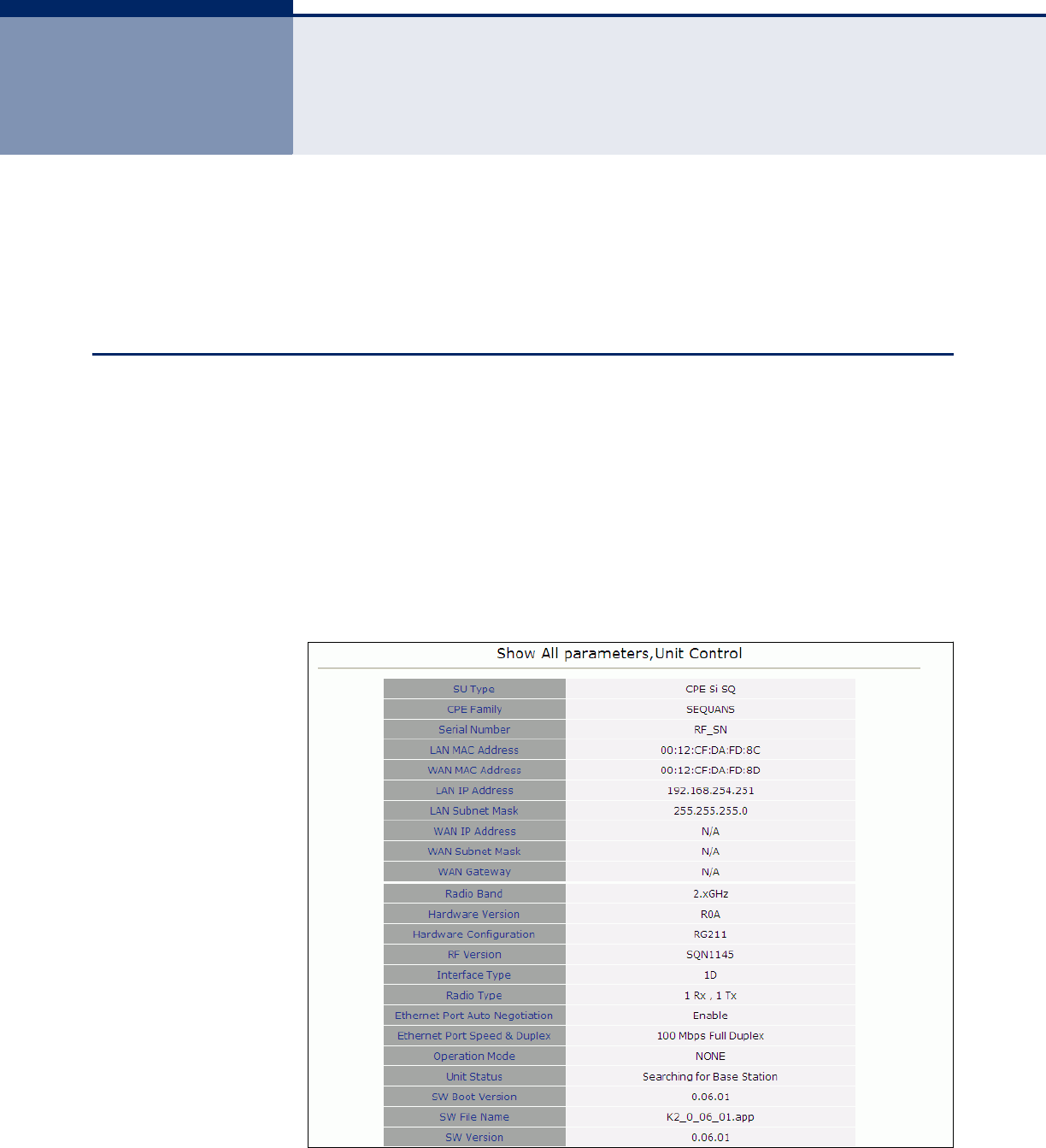
SHOW ALL The Show All parameters, Unit Control menu provides information on
thedefault system configuration and radio type.
Figure 33: Show All

C
HAPTER
10
| Status
System Status
– 61 –
The following items are displayed on the Show All page:
◆SU Type — Describes the service unit (SU) type.
◆CPE Family — Describes the primary chipset of the CPE.
◆Serial Number — Describes the serial number of the CPE unit. This
number can be used to determine the identity of the subscriber unit by
the base station operator.
◆LAN MAC Address — Describes the physical layer address of the LAN
port.
◆WAN MAC Address — The WAN port MAC address can be determined
by adding “1” to the LAN port MAC address.
◆LAN IP Address — The IP address of the LAN port.
◆LAN Subnet Mask — The LAN port subnet mask.
◆WAN IP Address — The IP address of the wireless WAN port.
◆WAN Subnet Mask — The subnet mask of the wireless WAN port.
◆WAN Gateway — The gateway address of the wireless WAN port.
◆Radio Band — Describes the radio band in use. The radio bands for the
CPE are 2.3, 2.5, 3.5 and 5 GHz.
◆Hardware version — Describes the revision of hardware in use.
◆Hardware configuration — Describes the identity of the current
hardware configuration by serial number.
◆RF version — Describes the radio frequency (RF) or rate of oscillation
of the electrical circuit.
◆SU Interface Type — Describes the number of ports available on the
interface. “D” refers to data ports, “V” refers to VoIP ports, with a prefix
number in use as a quantifier.
◆Radio Type — Describes the receive (Rx) and transmit (Tx) capacity of
the radio.
◆Ethernet Port Auto Negotiation — Describes the Ethernet port auto
negotiation enable/disable state.
◆Ethernet Port Speed & Duplex — Describes the speed and duplex
capabilities to which the Ethernet port has been set to.
◆Operation Mode — Describes the operation mode of the Extreme CPE,
either IPCS or ETHCS, where IPCS refers to transparent delivery of IPv4
packets and ETHCS refers to transparent delivery of tagged 802.3
packets over Ethernet.
C
HAPTER
10
| Status
System Status
– 62 –
◆Unit Status — Describes the connectivity status of the Extreme CPE to
the base station.
◆SW Boot Version — Describes the current software boot version file.
◆SW File Name — Describes the name of the current firmware.
◆SW Version — Describes the version of the current firmware.
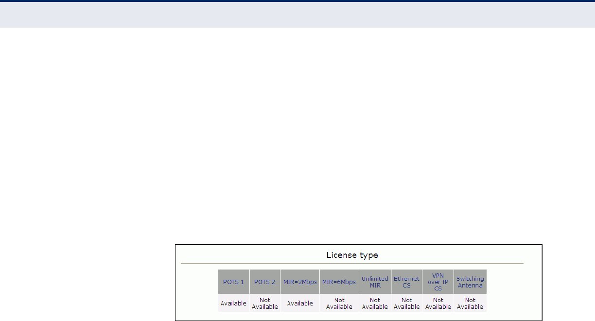
LICENCE TYPE Describes the availability of VoIP ports, operator preset maximum
information rates (MIR), Ethernet status, virtual private networks (VPN)
status and switching antenna status.
Figure 34: License Type
The following items are displayed on the License Type page:
◆POTS1/2 — Describes the availability status of the VoIP plain old
telephone service (POTS) ports. ‘Available’ indicates that the specified
VoIP port is open for use.
◆MIR=2Mbps — Describes the operator preset maximum information
rate (MIR) state per subscriber at 2Mbps upload/download.
◆MIR=6Mbps — Describes the operator preset maximum information
rate (MIR) state per subscriber at 6Mbps upload/download.
◆Unlimited MIR — Describes if the operator preset maximum
information rate (MIR) is unlimited in upload/download bandwidth, or
unavailable to the subscriber.
◆Ethernet CS — Describes the Ethernet convergence sublayer (CS)
status.
◆VPN over IP CS — Describes the status of the virtual private network
(VPN) over internet protocol (IP) convergence sublayer.
◆Switching Antenna — Describes the status of the switching antenna.
C
HAPTER
10
| Status
System Status
– 63 –
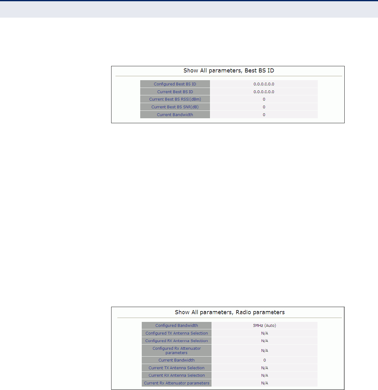
SHOW BEST BS ID Displays information on the base station identity (BSID), as well as signal
strength indication, noise ratio and bandwidth of the WiMAX connection.
Figure 35: Show Best BS ID
The following items are displayed on the Show All parameters, Best BS ID
page:
◆Configured Best BS ID — Describes the configured base station
identity, in the form xx.xx.xx.xx.xx.xx.
◆Current Best BS ID — Describes the identity of the best base station,
in the form xx.xx.xx.xx.xx.xx.
◆Current Best BS RSSI (dBm) — Describes the receive signal strength
indicator of the WiMAX link, in decibels per milliwatt.
◆Current Best BS SNR (dB) — Describes the signal to noise ratio of
the WiMAX link, in decibels.
◆Current Bandwidth — Describes the bandwidth of the WiMAX link.
SHOW RADIO
PARAMETERS
Radio Parameters display information on the bandwidth and antenna
selection of the CPE.
Figure 36: Show Radio Parameters
The following items are displayed on the Show All parameters, Radio
Parameters page:
C
HAPTER
10
| Status
System Status
– 64 –
◆Configured Bandwidth — Describes the configured bandwidth in
megahertz.
◆Configured Tx Antenna Selection — Describes the configured
tranmission antenna selection.
◆Configured Rx Antenna Selection — Describes the configured
receive antenna selection.
◆Configured Rx Attenuator Parameters — Describes the configured
receive signal after attenuation.
◆Current Bandwidth — Describes the current bandwidth of the WiMAX
link.
◆Current Tx Antenna Selection — Describes the current transmission
antenna selection.
◆Current Rx Antenna Selection — Describes the current receive
antenna selection.
◆Current Rx Attentuator Parameters — Describes the current receive
attenuator parameters.
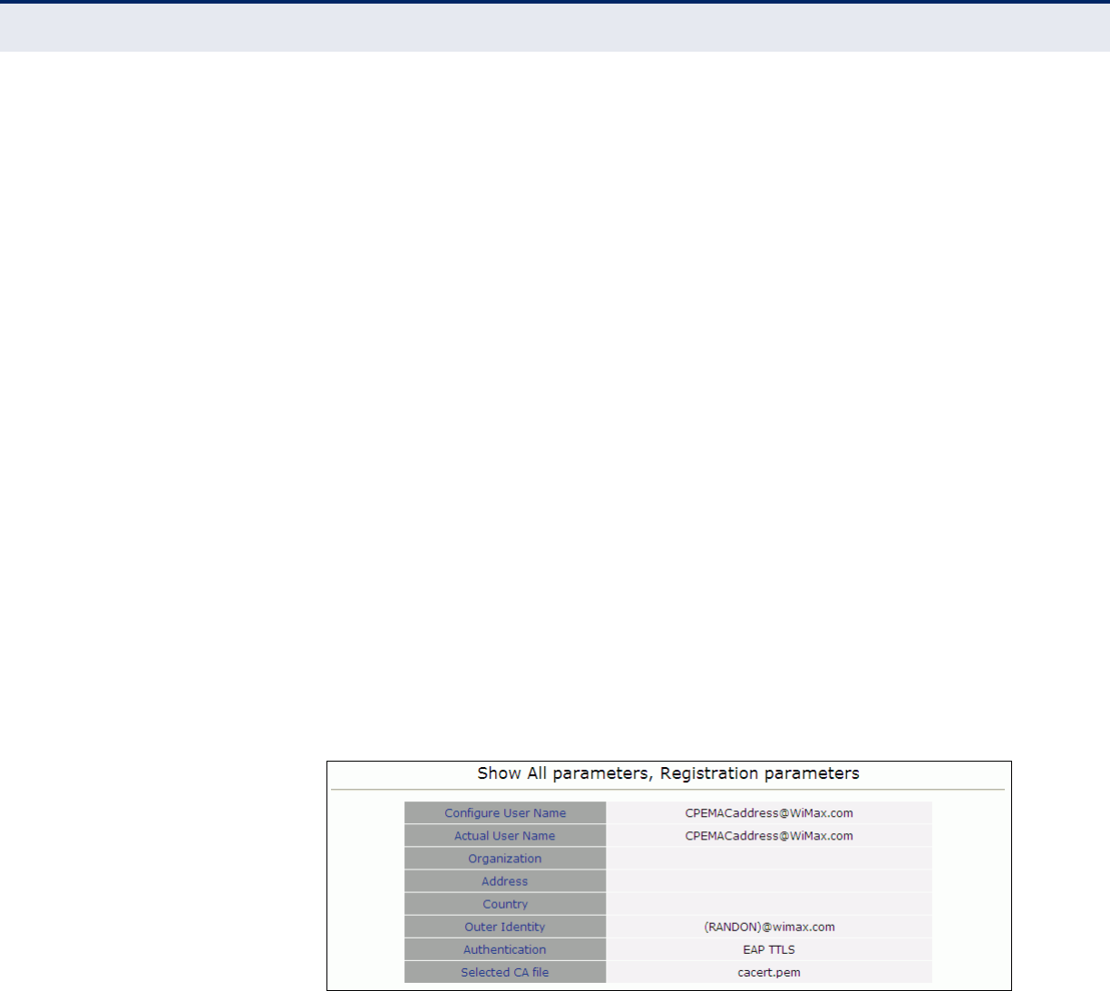
SHOW REGISTRATION Registration parameters displays information on the authentication
parameters required to support provisioning on the unit.
Figure 37: Show Registration
The following items are displayed on the Show All parameters, Registration
Parameters page:
◆Configure User Name — Describes the configured user name for the
unit.
◆Actual User Name — Describes the current name being used to
identify the user of the unit.
◆Organization — Describes the WiMAX subscriber name.

C
HAPTER
10
| Status
System Status
– 65 –
◆Address — Describes the contact information for the WiMAX
subscriber.
◆Country — Describes the country of operation.
◆Authentication — Describes the method of authentication being used
to secure the WiMAX connection.
◆Selected CA file — Describes the CA file in use for authentication.
– 66 –
11 LOGOUT
This chapter describes how to log out of the CPE. It includes the following
section:
◆“Logging Out” on page 66
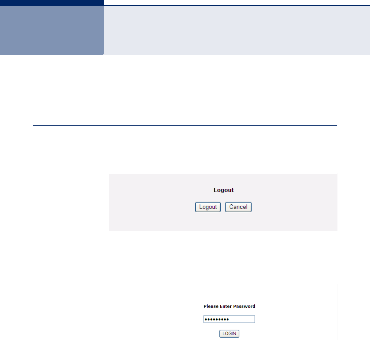
LOGGING OUT
The Logout page enables you to log out of the web interface and terminate
your session. Logging out is proceeded by a prompt to log in again.
Figure 38: Logout
The following items are displayed on the Logout page:
◆Logout — Logs you out of the current session.
Figure 39: Login
◆Login — Logs you into the system. The default password is “installer”.

C
HAPTER
11
| Logout
Logging Out
– 67 –


– 69 –
ATROUBLESHOOTING
DIAGNOSING LED INDICATORS
BEFORE CONTACTING TECHNICAL SUPPORT
Check the following items before you contact local Technical Support.
1. If wireless clients cannot access the network, check the following:
■If authentication or encryption are enabled, ensure that the wireless
clients are properly configured with the appropriate authentication
or encryption keys.
2. If the CPE cannot be configured using a web browser:
■Be sure to have configured the CPE with a valid IP address, subnet
mask and default gateway.
■Check that you have a valid network connection to the CPE and that
the Ethernet port or the wireless interface that you are using has
not been disabled.
■If you are connecting to the CPE through the wired Ethernet
interface, check the network cabling between the management
station and the CPE. If you are connecting to CPE from a wireless
client, ensure that you have a valid connection to the CPE.
Table 3: LED Indicators
Symptom Action
Power LED is off ◆The AC power adapter may be disconnected. Check
connections between the unit, the power adapter, and the
wall outlet.
LAN LED is off
(when port connected)
◆Verify that the unit and attached device are powered on.
◆Be sure the cable is plugged into both the unit and
corresponding device.
◆Verify that the proper cable type is used and its length does
not exceed specified limits.
◆Check the cable connections for possible defects. Replace the
defective cable if necessary.
WiMAX Signal Strength
LEDs are off
◆There is no detected signal from a WiMAX base station.
Check the radio settings in the management interface.

A
PPENDIX
A
| Troubleshooting
Before Contacting Technical Support
– 70 –
3. If you forgot or lost the password, contact technical support for
assistance.
4. If all other recovery measure fail, and the CPE is still not functioning
properly, take any of these steps:
■Reset the CPE’s hardware using the reset button, through the web
interface, or through a power reset. Then use the default password
“installer” to access the management interface.

– 71 –
BHARDWARE SPECIFICATIONS
WIMAX RADIO SPECIFICATIONS
RADIO TYPE IEEE 802.16e WAVE 1 & WAVE 2
FREQUENCY BAND
RANGE
2305~2360 MHz, or
2496~2690 MHz (FCC), 2500~2690 MHz (CE), or
3300~3600 MHz (CE), or
3600~3800 MHz
ANTENNA TYPE External Omni-dipole antenna with MRC function
CHANNEL BANDWIDTH 2.5G: 5.00 and 10.00 MHz
3.5G: 5.00, 7.00 and 10.00 MHz
MAXIMUM THROUGHPUT 5 Mbps Upload, 20 Mbps download
RADIO TECHNOLOGY Maximum-Ratio Combining (MRC)
MODULATION TECHNIQUE Scaleable OFDMA employing Time-Division Duplex (TDD) mechanism
PRBS subcarrier randomization
Contains pilot, preamble, and ranging modulation
FEC CODING RATES Down Link: QPSK, 16 QAM, 64 QAM
Up Link: QPSK, 16 QAM

A
PPENDIX
B
| Hardware Specifications
– 72 –
ANTENNA GAIN 2.3 GHz 5 dBi
2.5 GHz 5 dBi
3.5 GHz 6 dBi
3.8 GHz 6 dBi
TPL (TRANSMIT POWER
LEVEL)
+24~26 dBm maximum (+/- 2dBm)
RECEIVE SENSITIVITY -94 dBm maximum
VOIP SPECIFCATIONS
VOICE SIGNALLING
PROTOCOL
SIP v2 (RFC 3261)
VOICE CODECS G.711 (a-law and u-law)
G.729ab
G.722
G.722.1
VOICE QUALITY G.726 VAD (Voice Activity Detection)
G.723 CNG (Comfortable Noise Generation)
Echo cancellation (G.165/G.168)
Adaptive jitter buffer, up to 200 milliseconds
DTMF tone detection and generation
Configurable Cadence Rings
CALL FEATURES Call transfer
Call waiting/hold/retrieve
3-way conference call
Call blocking

A
PPENDIX
B
| Hardware Specifications
– 73 –
T.38 fax relay
Dial plan (E.164 dialing plan)
Call forwarding: No Answer/Busy/All
REN (RING EQUIVILENT
NUMBER)
3 REN total in system
CONFIGURATION AND MANAGEMENT
MANAGEMENT OPTIONS Web-based (HTTP/HTTPS)
MANAGEMENT ACCESS From Wired LAN, Wireless Link
MANAGEMENT ACCESS
PROTECTION
Access Password
ENCRYPTION PKMv2 with 128bit AES/CCM
ALLOCATION OF IP
PARAMETERS
Configurable or automatic (DHCP client)
SOFTWARE UPGRADE HTTP
CONFIGURATION
UPLOAD/DOWNLOAD
HTTP
MECHANICAL
DIMENSIONS TBC
WEIGHT TBC
MOUNTING Desktop or wall
CABLING Category 5 cable connection

A
PPENDIX
B
| Hardware Specifications
– 74 –
ELECTRICAL
AC POWER SUPPLY Input: 100-240 VAC, 50-60 Hz, maximum power consumption 1.0A
Output: 12 VDC @ 1.5A, maximum power consumption 18A
MTBF 5 years
Bellcore SR332
ENVIRONMENTAL
OPERATING
TEMPERATURE
-5ºC to 45ºC
STORAGE TEMPERATURE -40 to 75 °C
HUMIDITY Maximum 95%, non-condensing
STANDARDS COMPLIANCE
EMC FCC Part 15B Class B
EN 55022
EN 55022 + EN 55024 Class B
EN 301 489-1/4
SAFETY EN 60950-1 (2006)
WIMAX RADIO SIGNAL
CERTIFICATION
EN 302 326
FCC Part 27M
STANDARDS IEEE 802.16e-2005 WAVE 1 and WAVE 2
IEEE 802.3-2005 10BASE-T and 100BASE-TX
– 75 –
CCABLES AND PINOUTS
TWISTED-PAIR CABLE ASSIGNMENTS
For 10/100BASE-TX connections, a twisted-pair cable must have two pairs
of wires. Each wire pair is identified by two different colors. For example,
one wire might be green and the other, green with white stripes. Also, an
RJ-45 connector must be attached to both ends of the cable.
N
OTE
:
Each wire pair must be attached to the RJ-45 connectors in a specific
orientation.
C
AUTION
:
DO NOT plug a phone jack connector into the RJ-45 port. Use
only twisted-pair cables with RJ-45 connectors that conform with FCC
standards.
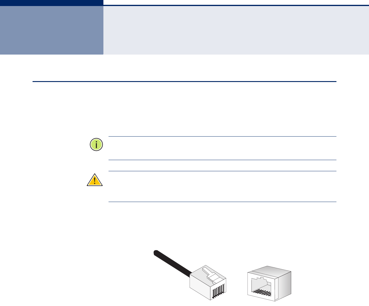
The following figure illustrates how the pins on the RJ-45 connector are
numbered. Be sure to hold the connectors in the same orientation when
attaching the wires to the pins.
Figure 40: RJ-45 Connector
10/100BASE-TX PIN
ASSIGNMENTS
Use unshielded twisted-pair (UTP) or shielded twisted-pair (STP) cable for
RJ-45 connections: 100-ohm Category 3 or better cable for 10 Mbps
connections. Also be sure that the length of any twisted-pair connection
does not exceed 100 meters (328 feet).
The RJ-45 port on the CPE supports automatic MDI/MDI-X operation, so
you can use straight-through or crossover cables for all network
connections to PCs, switches, or hubs. In straight-through cable, pins 1, 2,
3, and 6, at one end of the cable, are connected straight through to pins 1,
2, 3, and 6 at the other end of the cable.
81
1
8

A
PPENDIX
C
| Cables and Pinouts
Twisted-Pair Cable Assignments
– 76 –
STRAIGHT-THROUGH
WIRING
If the twisted-pair cable is to join two ports and only one of the ports has
an internal crossover (MDI-X), the two pairs of wires must be straight-
through. (When auto-negotiation is enabled for any RJ-45 port on this
switch, you can use either straight-through or crossover cable to connect
to any device type.)
You must connect all four wire pairs as shown in the following diagram to
support Gigabit Ethernet connections.
Figure 41: Straight Through Wiring
Table 4: 10/100BASE-TX MDI and MDI-X Port Pinouts
PIN MDI Signal Namea
a. The “+” and “-” signs represent the polarity of the wires that make up each wire
pair.
MDI-X Signal Name
1 Transmit Data plus (TD+)
-48V power (Negative Vport)
Receive Data plus (RD+)
GND (Positive Vport)
2 Transmit Data minus (TD-)
-48V power (Negative Vport)
Receive Data minus (RD-)
GND (Positive Vport)
3 Receive Data plus (RD+)
GND (Positive Vport)
Transmit Data plus (TD+)
-48V power (Negative Vport)
4-48V power (Negative V
port) GND (Positive Vport)
5-48V power (Negative V
port) GND (Positive Vport)
6 Receive Data minus (RD-)
GND (Positive Vport)
Transmit Data minus (TD-)
-48V power (Negative Vport)
7 GND (Positive Vport) -48V power (Negative Vport)
8 GND (Positive Vport) -48V power (Negative Vport)
White/Orange Stripe
Orange
White/Green Stripe
Green
1
2
3
4
5
6
7
8
1
2
3
4
5
6
7
8
EIA/TIA 568B RJ-45 Wiring Standard
10/100BASE-TX Straight-through Cable
End A End B
Blue
White/Blue Stripe
Brown
White/Brown Stripe
A
PPENDIX
C
| Cables and Pinouts
Twisted-Pair Cable Assignments
– 77 –
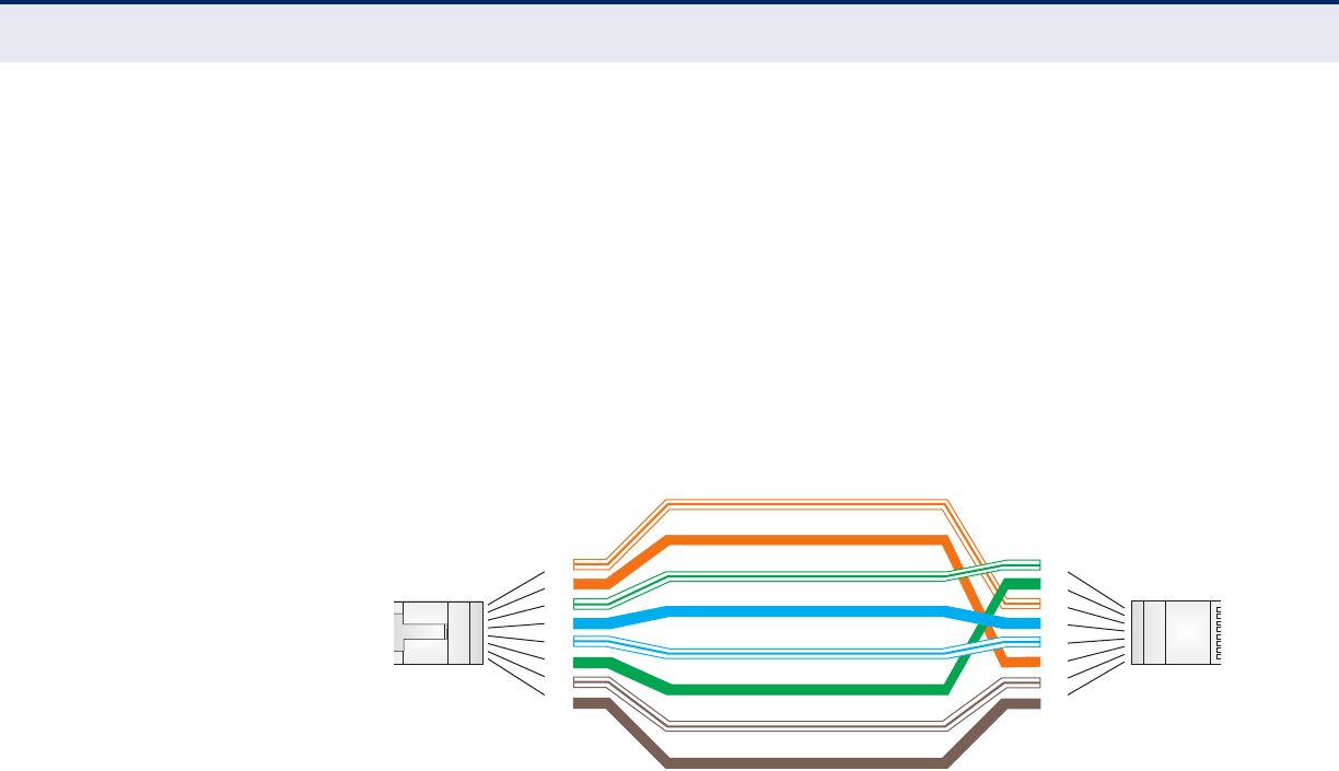
CROSSOVER WIRING If the twisted-pair cable is to join two ports and either both ports are
labeled with an “X” (MDI-X) or neither port is labeled with an “X” (MDI), a
crossover must be implemented in the wiring. (When auto-negotiation is
enabled for any RJ-45 port on this switch, you can use either straight-
through or crossover cable to connect to any device type.)
You must connect all four wire pairs as shown in the following diagram to
support Gigabit Ethernet connections.
Figure 42: Crossover Wiring
CABLE TESTING FOR EXISTING CATEGORY 5 CABLE
Installed Category 5 cabling must pass tests for Attenuation, Near-End
Crosstalk (NEXT), and Far-End Crosstalk (FEXT). This cable testing
information is specified in the ANSI/TIA/EIA-TSB-67 standard. Additionally,
cables must also pass test parameters for Return Loss and Equal-Level Far-
End Crosstalk (ELFEXT). These tests are specified in the ANSI/TIA/EIA-
TSB-95 Bulletin, “The Additional Transmission Performance Guidelines for
100 Ohm 4-Pair Category 5 Cabling.”
Note that when testing your cable installation, be sure to include all patch
cables between switches and end devices.
White/Orange Stripe
Orange
White/Green Stripe
1
2
3
4
5
6
7
8
1
2
3
4
5
6
7
8
EIA/TIA 568B RJ-45 Wiring Standard
10/100BASE-TX Crossover Cable
End A End B
Green
Blue
White/Blue Stripe
Brown
White/Brown Stripe

– 78 –
GLOSSARY
10BASE-T IEEE 802.3-2005 specification for 10 Mbps Ethernet over two pairs of
Category 3 or better UTP cable.
100BASE-TX IEEE 802.3-2005 specification for 100 Mbps Fast Ethernet over two pairs of
Category 5 or better UTP cable.
ADVANCED ENCRYPTION
STANDARD (AES)
An encryption algorithm that implements symmetric key cryptography. AES
provides very strong encryption using a completely different ciphering
algorithm to TKIP and WEP.
AUTHENTICATION The process to verify the identity of a client requesting network access.
IEEE 802.11 specifies two forms of authentication: open system and
shared key.
BACKBONE The core infrastructure of a network. The portion of the network that
transports information from one central location to another central location
where it is unloaded onto a local system.
BEACON A signal periodically transmitted from the CPE that is used to identify the
service set, and to maintain contact with wireless clients.
BROADCAST KEY Broadcast keys are sent to stations using dynamic keying. Dynamic
broadcast key rotation is often used to allow the CPE to generate a random
group key and periodically update all key-management capable wireless
clients.
DYNAMIC HOST
CONFIGURATION
PROTOCOL (DHCP)
Provides a framework for passing configuration information to hosts on a
TCP/IP network. DHCP is based on the Bootstrap Protocol (BOOTP), adding
the capability of automatic allocation of reusable network addresses and
additional configuration options.
ENCRYPTION Data passing between the CPE and clients can use encryption to protect
from interception and evesdropping.

G
LOSSARY
– 79 –
ETHERNET A popular local area data communications network, which accepts
transmission from computers and terminals.
FILE TRANSFER
PROTOCOL (FTP)
A TCP/IP protocol used for file transfer.
HYPERTEXT TRANSFER
PROTOCOL (HTTP)
HTTP is a standard used to transmit and receive all data over the World
Wide Web.
INFRASTRUCTURE An integrated wireless and wired LAN is called an infrastructure
configuration.
LOCAL AREA NETWORK
(LAN)
A group of interconnected computer and support devices.
MAC ADDRESS The physical layer address used to uniquely identify network nodes.
NETWORK TIME
PROTOCOL (NTP)
NTP provides the mechanisms to synchronize time across the network. The
time servers operate in a hierarchical-master-slave configuration in order
to synchronize local clocks within the subnet and to national time
standards via wire or radio.
OPEN SYSTEM A security option which broadcasts a beacon signal including the CPE’s
configured SSID. Wireless clients can read the SSID from the beacon, and
automatically reset their SSID to allow immediate connection to the
nearest CPE.
ORTHOGONAL
FREQUENCY DIVISION
MULTIPLEXING (ODFM)
OFDM allows multiple users to transmit in an allocated band by dividing the
bandwidth into many narrow bandwidth carriers.
SERVICE SET IDENTIFIER
(SSID)
An identifier that is attached to packets sent over the wireless LAN and
functions as a password for joining a particular radio cell; i.e., Basic Service
Set (BSS).
SESSION KEY Session keys are unique to each client, and are used to authenticate a
client connection, and correlate traffic passing between a specific client and
the CPE.

G
LOSSARY
– 80 –
SHARED KEY A shared key can be used to authenticate each client attached to a wireless
network. Shared Key authentication must be used along with the 802.11
Wireless Equivalent Privacy algorithm.
SIMPLE NETWORK TIME
PROTOCOL (SNTP)
SNTP allows a device to set its internal clock based on periodic updates
from a Network Time Protocol (NTP) server. Updates can be requested from
a specific NTP server, or can be received via broadcasts sent by NTP
servers.
TEMPORAL KEY
INTEGRITY PROTOCOL
(TKIP)
A data encryption method designed as a replacement for WEP. TKIP avoids
the problems of WEP static keys by dynamically changing data encryption
keys.
TRIVIAL FILE TRANSFER
PROTOCOL (TFTP)
A TCP/IP protocol commonly used for software downloads.
VIRTUAL CPE (VAP) Virtual AP technology multiplies the number of CPEs present within the RF
footprint of a single physical access device. With Virtual AP technology,
WLAN users within the device.s footprint can associate with what appears
to be different CPEs and their associated network services. All the services
are delivered using a single radio channel, enabling Virtual AP technology
to optimize the use of limited WLAN radio spectrum.
WI-FI PROTECTED
ACCESS
WPA employs 802.1X as its basic framework for user authentication and
dynamic key management to provide an enhanced security solution for
802.11 wireless networks.
WIRED EQUIVALENT
PRIVACY (WEP)
WEP is based on the use of security keys and the popular RC4 encryption
algorithm. Wireless devices without a valid WEP key will be excluded from
network traffic.
WPA PRE-SHARED KEY
(WPA-PSK)
WPA-PSK can be used for small office networks with a limited number of
users that may not need a high level of security. WPA-PSK provides a
simple security implementation that uses just a pre-shared password for
network access.

– 81 –
INDEX
A
antennas 17
B
best BST/AU 34
C
configuration control 55
connect Ethernet cable 25
connecting and powering on 25
D
diagnosing LED indicators 69
DMZ 48
E
Ethernet mode 33
Ethernet on-line counters 40
Ethernet port 19
F
firewall settings 50
frequency scanning 37
parameters 37
scanning table 38
H
hardware description 15
I
initial configuration 26
installing the access point 22
integration time 42
introduction 13
K
key features 13
L
LAN settings 31
LED indicators 18
link quality counters 39
location selection 22
logging out 66
M
mounting on a horizontal surface 23
mounting on a wall 24
N
NAT settings 46
P
package contents 14
password 53
position antennas 25
power connector 19
R
reset button 19
resetting the unit 52
S
security settings 44
CA file 45
user registration 44
self test 25
SNTP 32
software version control 54
system settings 29
system status 60
licence type 62
show all 60
show best BS ID 63
show radio parameters 63
show registration 64
T
TM and PM upload control 56
TR-069 57
V
virtual server 47


I
NDEX
– 83 –

RG211-81
E122009-DT-R01
149100000033W