Accton Wireless Broand FW181RG30002W WiMAX 802.16e Indoor Gateway User Manual User s guide
Accton Wireless Broadband Corp. WiMAX 802.16e Indoor Gateway User s guide
UserManual.wiki
>
Accton Wireless Broand
>
FW181RG30002W User Manual
User Manual
Navigation menu
Upload a User Manual
Namespaces
Wiki Guide
HTML
PDF
Info
Views
User Manual
Discussion / Help
Navigation

![0560esky[Czech] [Jm no v robce] t mtoprohla uje, etento [typza zen ] jeveshod sezkladnmipo adavkyadal mi p slu n miustanoven mism rnice1999/5/ES.Dansk[Danish] Undertegnede [fabrikantensnavn] erkl rerherved,at f lgendeudstyr[udstyretstypebetegnelse] overholderde v sentligekrav og vrige relevantekravidirektiv1999/5/EF.Deutsch[German] Hiermiterkl rt [NamedesHerstellers],dass sichdasGer t [Ger tetyp] inbereinstimmungmitdengrundlegendenAnforderungenundden brigeneinschl gigenBestimmungenderRichtlinie1999/5/EGbefindet.Eesti[Estonian] Kesolevagakinnitab [tootja nimi= nameofmanufacturer] seadme [seadmetp=typeofequipment] vastavustdirektiivi1999/5/E p hin uetelejanimetatuddirektiivisttulenevateleteisteleasjakohastele s tetele.English Hereby, [nameofmanufacturer],declaresthatthis [type ofequipment] isincompliancewiththeessentialrequirementsand otherrelevantprovisionsofDirective1999/5/EC.Espa ol[Spanish] Pormediodelapresente [nombredelfabricante] declaraqueel [clasedeequipo] cumpleconlosrequisitosesencialesycualesquiera otrasdisposicionesaplicables o exigiblesdela Directiva1999/5/CE.[Greek] [nameofmanufacturer] [typeofequipment]1999/5/ .Fran ais[French] Parlapr sente [nomdufabricant] d clarequel'appareil [typed'appareil] estconformeauxexigencesessentiellesetauxautresdispositionspertinentesdeladirective1999/5/CE.Italiano[Italian] Conlapresente [nomedelcostruttore] dichiarachequesto [tipodiapparecchio] conformeairequisitiessenzialiedallealtredisposizionipertinenti stabilitedalladirettiva1999/5/CE.Latviski[Latvian] Ar o [name ofmanufacturer/izgatavot janosaukums] deklar ,ka [type ofequipment/iek rtastips] atbilstDirektvas1999/5/EK b tiskaj mprasb muncitiemarto saist tajiem noteikumiem.Lietuvi[Lithuanian] iuo [manufacturer name] deklaruoja,kad is [equipmenttype] atitinkaesminiusreikalavimusirkitas1999/5/EB Direktyvosnuostatas.Nederlands[Dutch]Hierbijverklaart [naamvandefabrikant]dat hettoestel [typevantoestel] inovereenstemmingismetdeessenti leeisenendeandere relevantebepalingenvanrichtlijn1999/5/EG.Malti[Maltese] Hawnhekk, [isemtal-manifattur],jiddikjaralidan [il-mudeltal-prodott]jikkonformamal- ti ijietessenzjaliumaprovvedimenti o rajnrelevantili hemmfid-Dirrettiva1999/5/EC.Magyar[Hungarian] Alul rott, [gy rt neve] nyilatkozom,hogya[... tpus] megfelelavonatkozalapvet k vetelm nyeknek saz1999/5/ECir nyelvegy bel r sainak.](https://usermanual.wiki/Accton-Wireless-Broand/FW181RG30002W/User-Guide-1456474-Page-6.png)
![Polski[Polish] Niniejszym [nazwaproducenta] o wiadcza, e [nazwa wyrobu] jestzgodnyzzasadniczymiwymogamiorazpozosta ymistosownymipostanowieniamiDyrektywy1999/5/EC.Portugu s[Portuguese][Nomedofabricante] declaraqueeste [tipodeequipamento] est conformecomos requisitosessenciaise outrasdisposi esda Directiva1999/5/CE.Slovensko[Slovenian] [Imeproizvajalca] izjavlja,dajeta [tip opreme] v skladuzbistvenimizahtevamiinostalimirelevantnimidolo ilidirektive1999/5/ES.Slovensky[Slovak] [Meno v robcu] t mtovyhlasuje, e [typzariadenia] sp a z kladn po iadavkya v etkypr slu n ustanoveniaSmernice1999/5/ES.Suomi[Finnish] [Valmistaja=manufacturer] vakuuttaa t tenett [typeofequipment=laitteentyyppimerkint ] tyyppinenlaite on direktiivin1999/5/EY oleellistenvaatimustenjasit koskeviendirektiivinmuidenehtojenmukainen.Svenska[Swedish] Hrmedintygar [f retag] attdenna [utrustningstyp] st rI verensst mmelsemedde v sentligaegenskapskrav och vrigarelevantabest mmelsersomframg ravdirektiv1999/5/EG.](https://usermanual.wiki/Accton-Wireless-Broand/FW181RG30002W/User-Guide-1456474-Page-7.png)


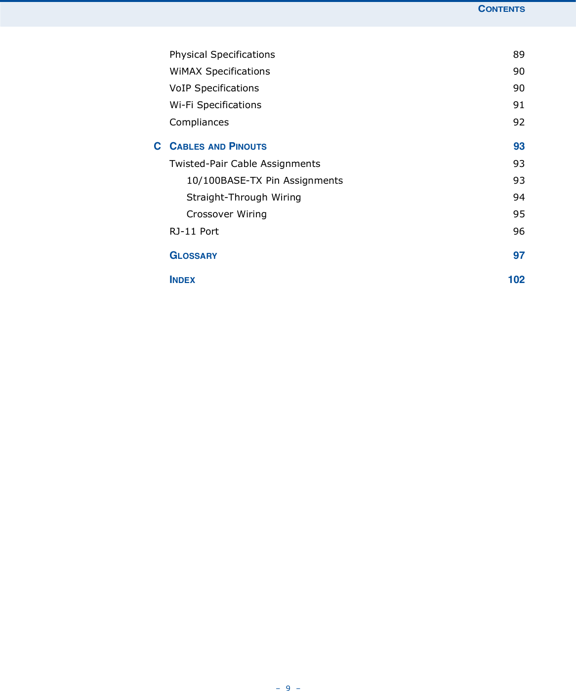


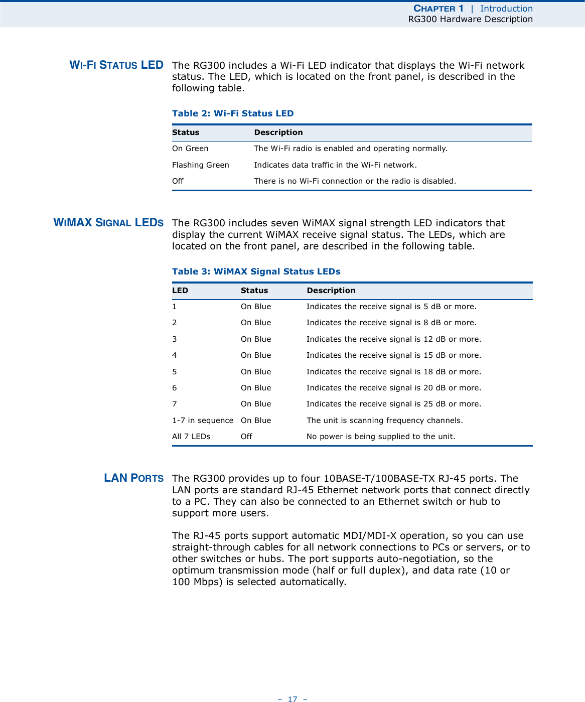


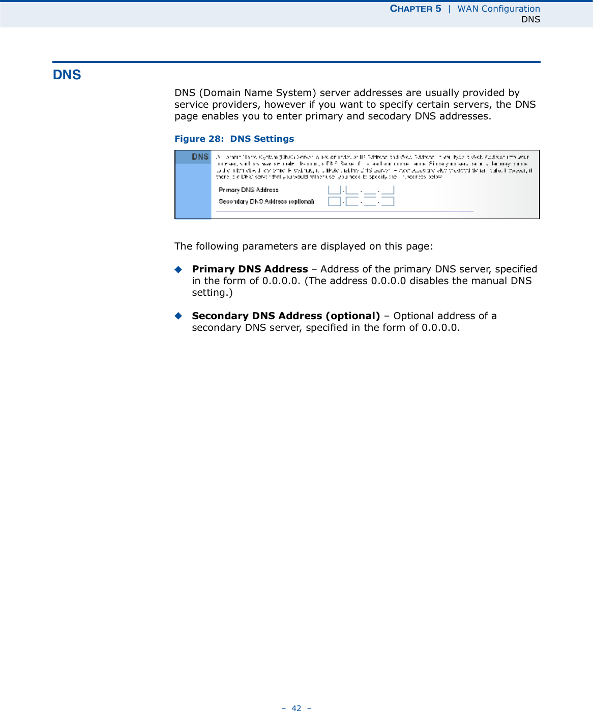


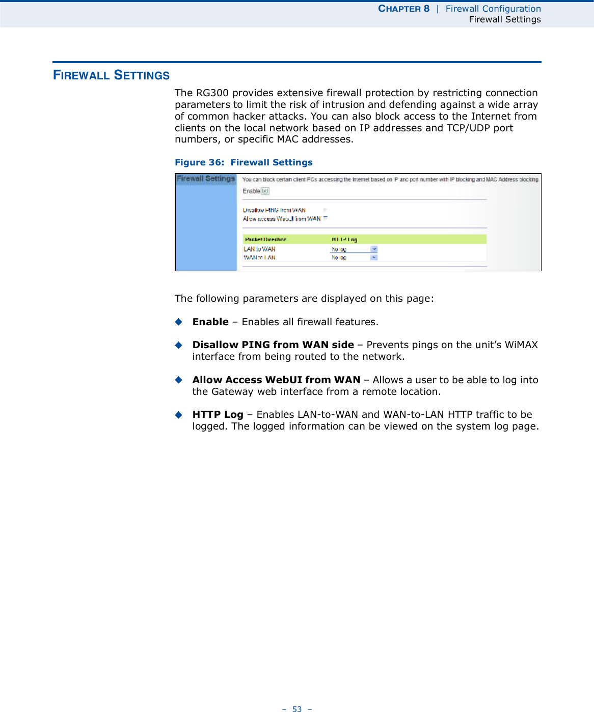


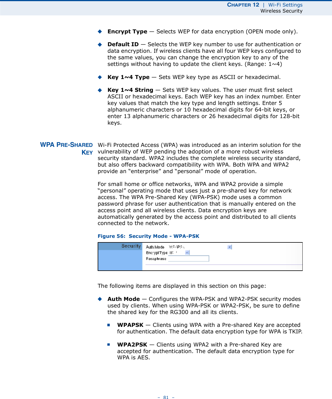
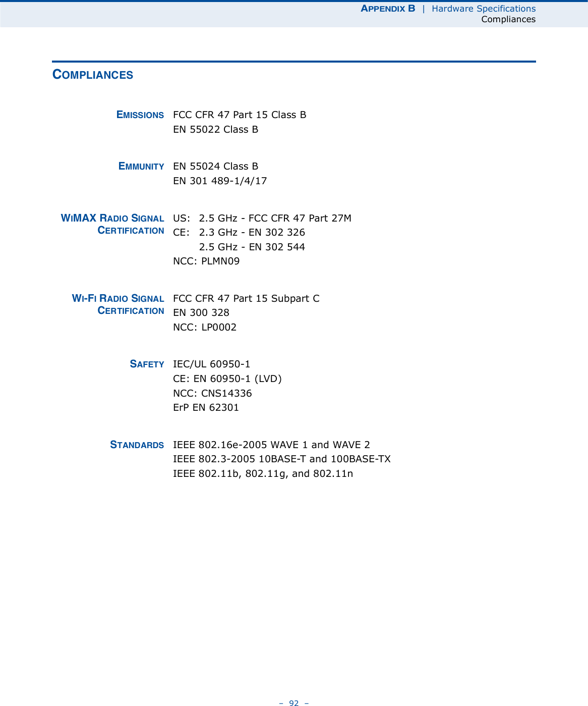
![ÝØßÐÌÛÎ è | Firewall ConfigurationURL Filtering 57 ËÎÔ Ú×ÔÌÛÎ×ÒÙThe RG300 provides a method for blocking Internet access based on Uniform Resource Locator (URL) keywords. By filtering URLs accessed from the network, users can be prevented from reaching prohibited online content.Figure 40: URL FilteringThe following items are displayed on this page:String $ Specifies text keyword contained in URLs that will be filtered. (Maximum 256 characters; invalid characters [% " & ' # \].)Add $ Adds a keyword string to the URL filter. Remove Removes an entry from the filter table.](https://usermanual.wiki/Accton-Wireless-Broand/FW181RG30002W/User-Guide-1456474-Page-61.png)
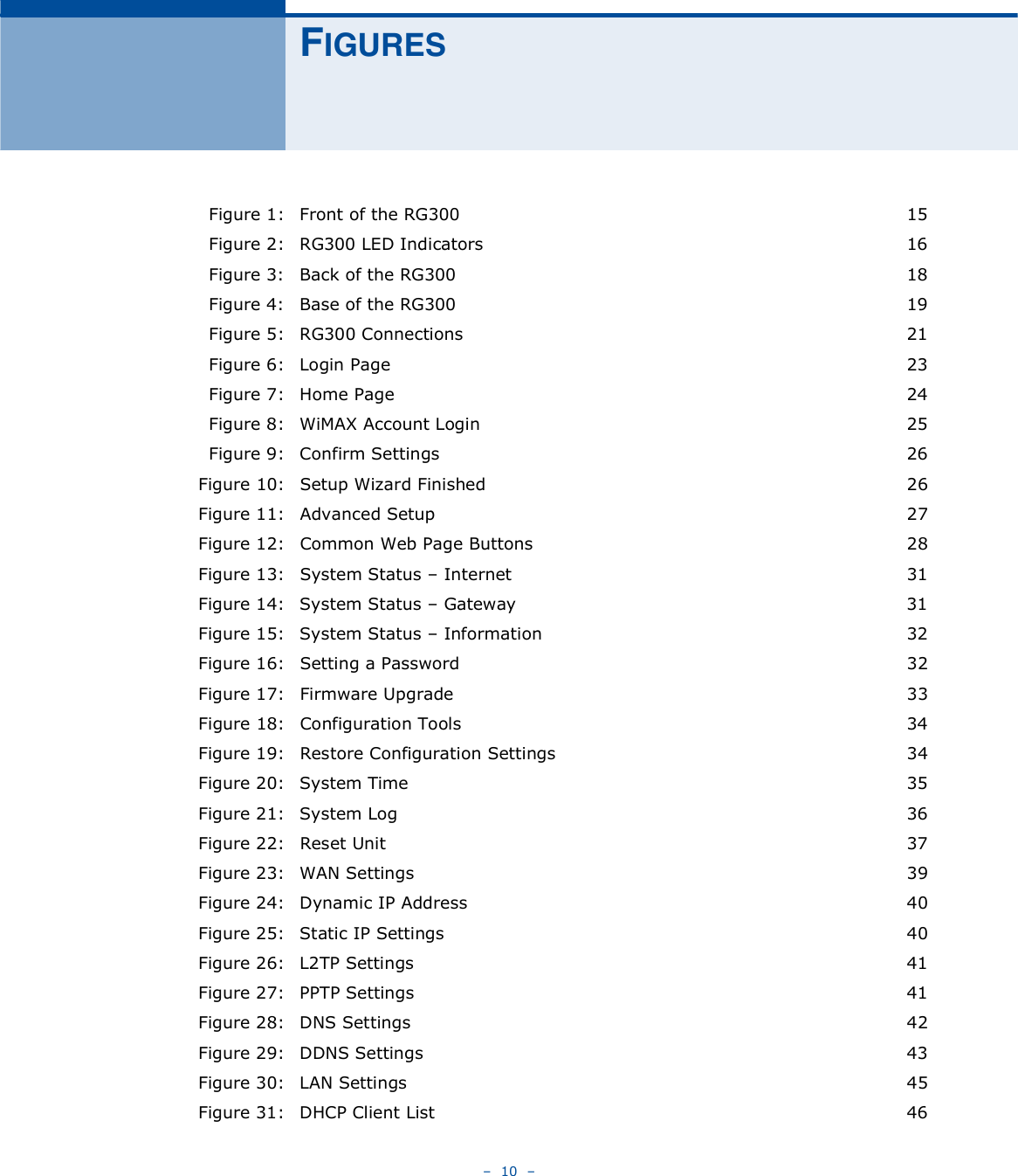
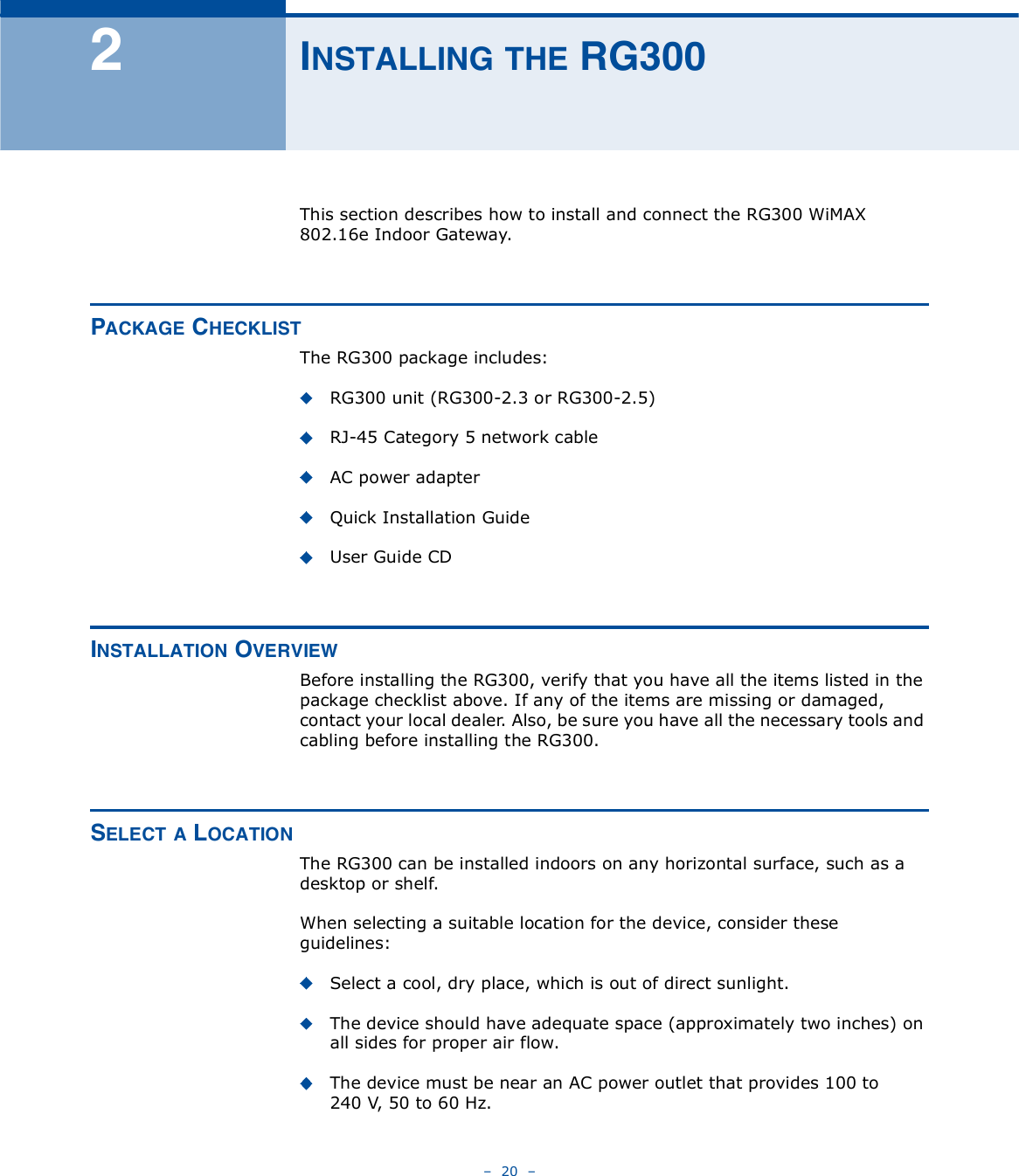
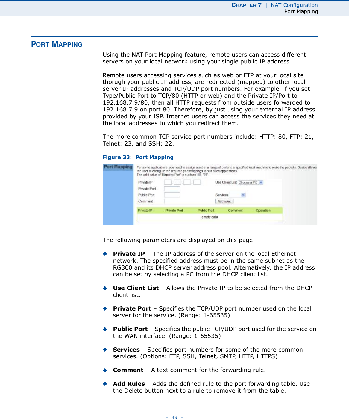
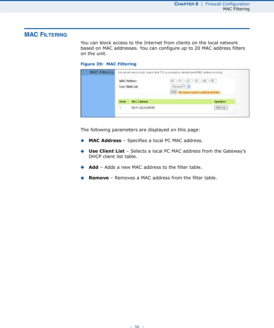
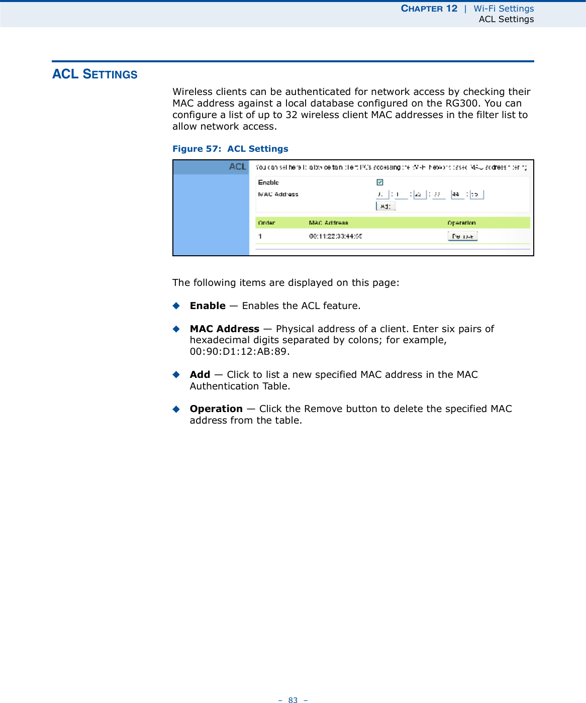
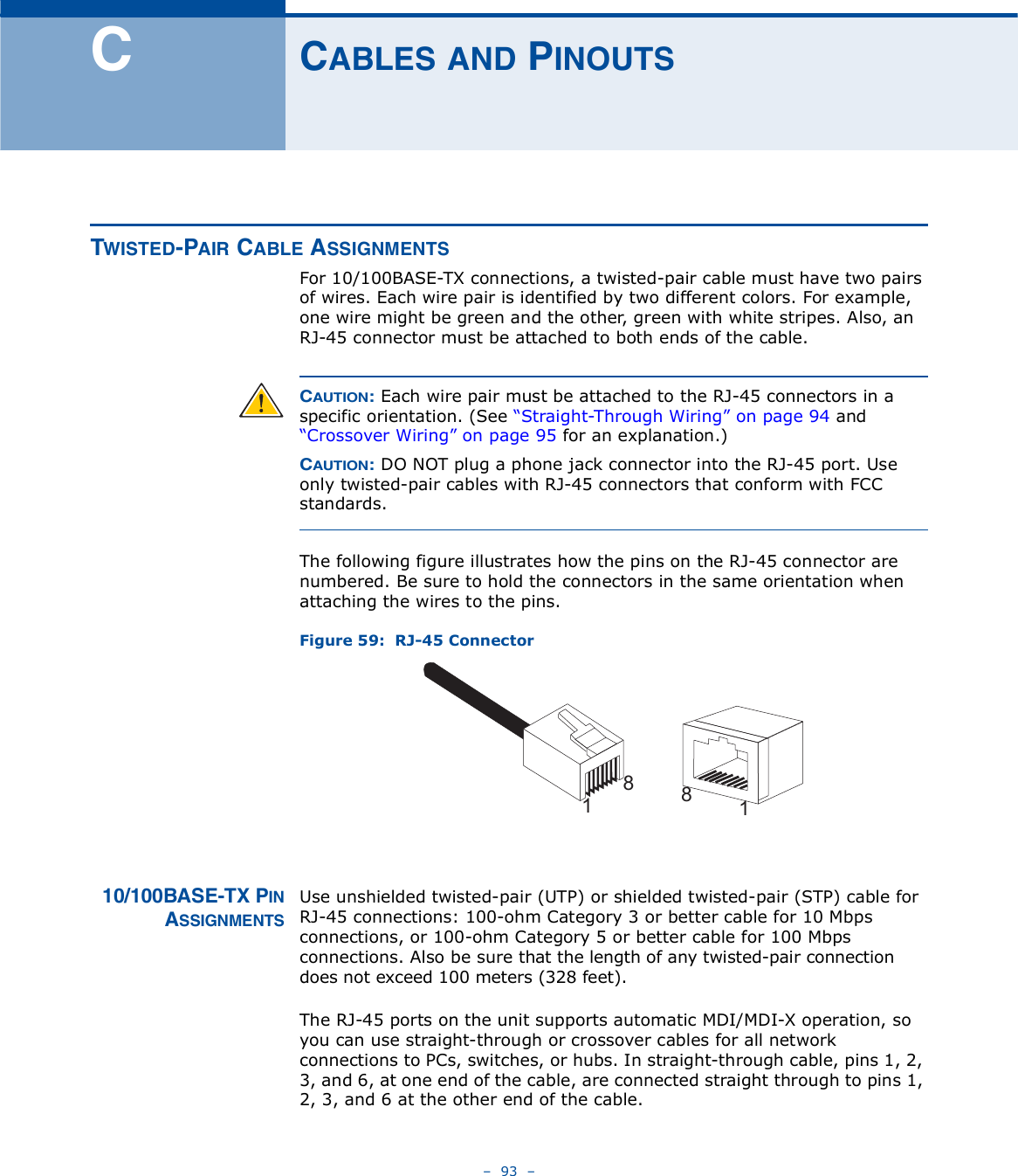
![ÝØßÐÌÛÎ è | Firewall ConfigurationHost Filtering 58 ØÑÍÌ Ú×ÔÌÛÎ×ÒÙThe RG300 provides a method for blocking Internet access based on web domains. A domain name is the name of a particular web site. For example, www.fungames.com. Figure 41: Host FilteringThe following items are displayed on this page:Host String $ Displays current Host filter. (Maximum 256 characters; invalid characters [% " & ' # \].)Add $ Enters a domain name keyword for a host filtering. For example, myhost.example.com.Remove $ Removes an entry from the filter table.](https://usermanual.wiki/Accton-Wireless-Broand/FW181RG30002W/User-Guide-1456474-Page-62.png)


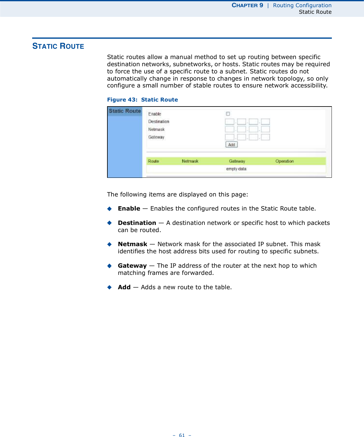

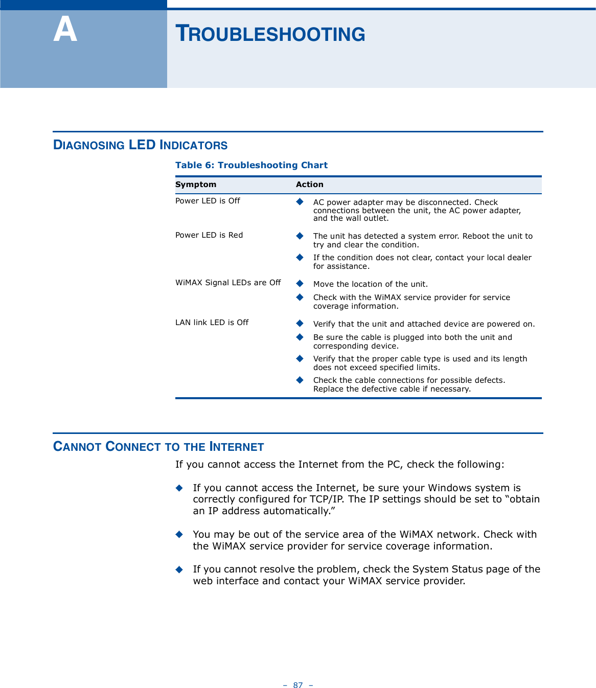
![ÝØßÐÌÛÎ ïï | VoIP SettingsDial Plan 68 Ü×ßÔ ÐÔßÒDial-plan strings specify key sequences used for specific calling features (Transfer, New Call, 3-way conference), as well as defining call restriction filters.A dial plan can filter the number and pattern of digits that a user dials to reach a particular telephone number. Access codes, area codes, specialized codes, and combinations of the number of digits dialed can all be part of a dial plan. This enables a user to predefine dialling sequences that are permitted. The dial-plan string consists of a single digit rule. A typical example of a dial-plan string is: [0123]xxxxxx.tFive standard dial plans are defined; Call Transfer Key, New Call Key, Set Speed Dial Key, Speed Dial Key, and 3-way Conference. Up to 10 other dial plans can be defined by the user.Figure 48: Dial Plan SettingsThe function of elements allowed in a dial plan are described in the table below:Table 5: Dial Plan ElementsElement Example DescriptionxxxxxRepresents a digit of any value ( 0 to 9) that can be dialed on a phone. This example has a rule with four digits of any number..xx. Indicates zero or more occurrences of the previous symbol. The example acts like a wildcard, meaning any dialed phone number of two or more digits is allowed.0-901xxIndicates dialed digits that must be matched. This example only allows four-digit numbers starting "01.#](https://usermanual.wiki/Accton-Wireless-Broand/FW181RG30002W/User-Guide-1456474-Page-72.png)
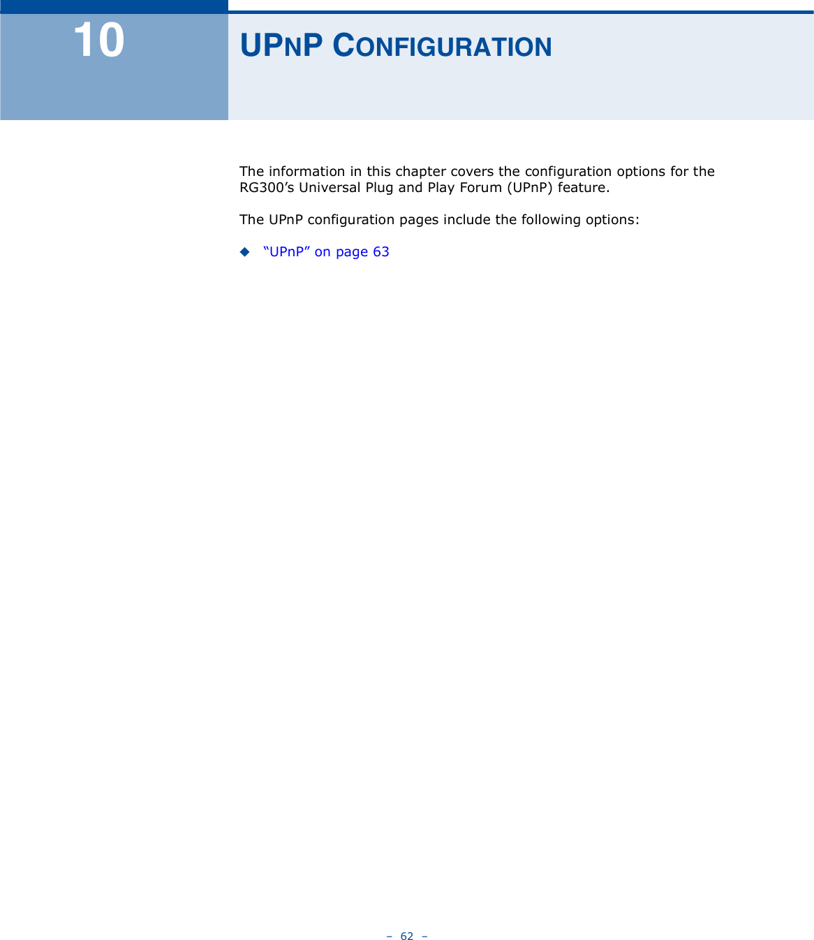
![ÝØßÐÌÛÎ ïï | VoIP SettingsDial Plan 69 When a user dials a series of digits, the dial-plan rule is tested for a possible match. If a match is made, the dialed sequence is transmitted. If no match is made, the dialed number is blocked and the user will hear an error tone.A dial-plan string cannot include spaces between elements. Dialed sequences that are longer than specified in a dial-plan rule are truncated after the number of specified digits. For example, if the dial-plan rule is "011x# and "0115678# is dialed, only the digit sequence "0115# is transmitted. [ ][125-8] Limits a dialed digit to specified values or a range of values. The example specifies that only digits 1, 2, 5, 6, 7, and 8 are permitted.txx.tThe timeout indicator that can placed after dialed digits or at the end of the dial-plan string.Table 5: Dial Plan ElementsElement Example Description](https://usermanual.wiki/Accton-Wireless-Broand/FW181RG30002W/User-Guide-1456474-Page-73.png)


![0560esky[Czech] [Jm no v robce] t mtoprohla uje, etento [typza zen ] jeveshod sezkladnmipo adavkyadal mi p slu n miustanoven mism rnice1999/5/ES.Dansk[Danish] Undertegnede [fabrikantensnavn] erkl rerherved,at f lgendeudstyr[udstyretstypebetegnelse] overholderde v sentligekrav og vrige relevantekravidirektiv1999/5/EF.Deutsch[German] Hiermiterkl rt [NamedesHerstellers],dass sichdasGer t [Ger tetyp] inbereinstimmungmitdengrundlegendenAnforderungenundden brigeneinschl gigenBestimmungenderRichtlinie1999/5/EGbefindet.Eesti[Estonian] Kesolevagakinnitab [tootja nimi= nameofmanufacturer] seadme [seadmetp=typeofequipment] vastavustdirektiivi1999/5/E p hin uetelejanimetatuddirektiivisttulenevateleteisteleasjakohastele s tetele.English Hereby, [nameofmanufacturer],declaresthatthis [type ofequipment] isincompliancewiththeessentialrequirementsand otherrelevantprovisionsofDirective1999/5/EC.Espa ol[Spanish] Pormediodelapresente [nombredelfabricante] declaraqueel [clasedeequipo] cumpleconlosrequisitosesencialesycualesquiera otrasdisposicionesaplicables o exigiblesdela Directiva1999/5/CE.[Greek] [nameofmanufacturer] [typeofequipment]1999/5/ .Fran ais[French] Parlapr sente [nomdufabricant] d clarequel'appareil [typed'appareil] estconformeauxexigencesessentiellesetauxautresdispositionspertinentesdeladirective1999/5/CE.Italiano[Italian] Conlapresente [nomedelcostruttore] dichiarachequesto [tipodiapparecchio] conformeairequisitiessenzialiedallealtredisposizionipertinenti stabilitedalladirettiva1999/5/CE.Latviski[Latvian] Ar o [name ofmanufacturer/izgatavot janosaukums] deklar ,ka [type ofequipment/iek rtastips] atbilstDirektvas1999/5/EK b tiskaj mprasb muncitiemarto saist tajiem noteikumiem.Lietuvi[Lithuanian] iuo [manufacturer name] deklaruoja,kad is [equipmenttype] atitinkaesminiusreikalavimusirkitas1999/5/EB Direktyvosnuostatas.Nederlands[Dutch]Hierbijverklaart [naamvandefabrikant]dat hettoestel [typevantoestel] inovereenstemmingismetdeessenti leeisenendeandere relevantebepalingenvanrichtlijn1999/5/EG.Malti[Maltese] Hawnhekk, [isemtal-manifattur],jiddikjaralidan [il-mudeltal-prodott]jikkonformamal- ti ijietessenzjaliumaprovvedimenti o rajnrelevantili hemmfid-Dirrettiva1999/5/EC.Magyar[Hungarian] Alul rott, [gy rt neve] nyilatkozom,hogya[... tpus] megfelelavonatkozalapvet k vetelm nyeknek saz1999/5/ECir nyelvegy bel r sainak.](https://usermanual.wiki/Accton-Wireless-Broand/FW181RG30002W/User-Guide-1456474-Page-111.png)
![Polski[Polish] Niniejszym [nazwaproducenta] o wiadcza, e [nazwa wyrobu] jestzgodnyzzasadniczymiwymogamiorazpozosta ymistosownymipostanowieniamiDyrektywy1999/5/EC.Portugu s[Portuguese][Nomedofabricante] declaraqueeste [tipodeequipamento] est conformecomos requisitosessenciaise outrasdisposi esda Directiva1999/5/CE.Slovensko[Slovenian] [Imeproizvajalca] izjavlja,dajeta [tip opreme] v skladuzbistvenimizahtevamiinostalimirelevantnimidolo ilidirektive1999/5/ES.Slovensky[Slovak] [Meno v robcu] t mtovyhlasuje, e [typzariadenia] sp a z kladn po iadavkya v etkypr slu n ustanoveniaSmernice1999/5/ES.Suomi[Finnish] [Valmistaja=manufacturer] vakuuttaa t tenett [typeofequipment=laitteentyyppimerkint ] tyyppinenlaite on direktiivin1999/5/EY oleellistenvaatimustenjasit koskeviendirektiivinmuidenehtojenmukainen.Svenska[Swedish] Hrmedintygar [f retag] attdenna [utrustningstyp] st rI verensst mmelsemedde v sentligaegenskapskrav och vrigarelevantabest mmelsersomframg ravdirektiv1999/5/EG.](https://usermanual.wiki/Accton-Wireless-Broand/FW181RG30002W/User-Guide-1456474-Page-112.png)


![ÝØßÐÌÛÎ è | Firewall ConfigurationURL Filtering 57 ËÎÔ Ú×ÔÌÛÎ×ÒÙThe RG300 provides a method for blocking Internet access based on Uniform Resource Locator (URL) keywords. By filtering URLs accessed from the network, users can be prevented from reaching prohibited online content.Figure 40: URL FilteringThe following items are displayed on this page:String $ Specifies text keyword contained in URLs that will be filtered. (Maximum 256 characters; invalid characters [% " & ' # \].)Add $ Adds a keyword string to the URL filter. Remove Removes an entry from the filter table.](https://usermanual.wiki/Accton-Wireless-Broand/FW181RG30002W/User-Guide-1456474-Page-168.png)
![ÝØßÐÌÛÎ è | Firewall ConfigurationHost Filtering 58 ØÑÍÌ Ú×ÔÌÛÎ×ÒÙThe RG300 provides a method for blocking Internet access based on web domains. A domain name is the name of a particular web site. For example, www.fungames.com. Figure 41: Host FilteringThe following items are displayed on this page:Host String $ Displays current Host filter. (Maximum 256 characters; invalid characters [% " & ' # \].)Add $ Enters a domain name keyword for a host filtering. For example, myhost.example.com.Remove $ Removes an entry from the filter table.](https://usermanual.wiki/Accton-Wireless-Broand/FW181RG30002W/User-Guide-1456474-Page-169.png)


![ÝØßÐÌÛÎ ïï | VoIP SettingsDial Plan 68 Ü×ßÔ ÐÔßÒDial-plan strings specify key sequences used for specific calling features (Transfer, New Call, 3-way conference), as well as defining call restriction filters.A dial plan can filter the number and pattern of digits that a user dials to reach a particular telephone number. Access codes, area codes, specialized codes, and combinations of the number of digits dialed can all be part of a dial plan. This enables a user to predefine dialling sequences that are permitted. The dial-plan string consists of a single digit rule. A typical example of a dial-plan string is: [0123]xxxxxx.tFive standard dial plans are defined; Call Transfer Key, New Call Key, Set Speed Dial Key, Speed Dial Key, and 3-way Conference. Up to 10 other dial plans can be defined by the user.Figure 48: Dial Plan SettingsThe function of elements allowed in a dial plan are described in the table below:Table 5: Dial Plan ElementsElement Example DescriptionxxxxxRepresents a digit of any value ( 0 to 9) that can be dialed on a phone. This example has a rule with four digits of any number..xx. Indicates zero or more occurrences of the previous symbol. The example acts like a wildcard, meaning any dialed phone number of two or more digits is allowed.0-901xxIndicates dialed digits that must be matched. This example only allows four-digit numbers starting "01.#](https://usermanual.wiki/Accton-Wireless-Broand/FW181RG30002W/User-Guide-1456474-Page-179.png)
![ÝØßÐÌÛÎ ïï | VoIP SettingsDial Plan 69 When a user dials a series of digits, the dial-plan rule is tested for a possible match. If a match is made, the dialed sequence is transmitted. If no match is made, the dialed number is blocked and the user will hear an error tone.A dial-plan string cannot include spaces between elements. Dialed sequences that are longer than specified in a dial-plan rule are truncated after the number of specified digits. For example, if the dial-plan rule is "011x# and "0115678# is dialed, only the digit sequence "0115# is transmitted. [ ][125-8] Limits a dialed digit to specified values or a range of values. The example specifies that only digits 1, 2, 5, 6, 7, and 8 are permitted.txx.tThe timeout indicator that can placed after dialed digits or at the end of the dial-plan string.Table 5: Dial Plan ElementsElement Example Description](https://usermanual.wiki/Accton-Wireless-Broand/FW181RG30002W/User-Guide-1456474-Page-180.png)