Accton Wireless Broand FW181RG30002W WiMAX 802.16e Indoor Gateway User Manual User s guide
Accton Wireless Broadband Corp. WiMAX 802.16e Indoor Gateway User s guide
User Manual

Ë
ÍÛÎ
Ù
Ë×ÜÛ
É×ÓßÈ èðîòïêÛ ×ÒÜÑÑÎ ÙßÌÛÉßÇ
ÎÙíðð

Ë
ÍÛÎ
Ù
Ë×ÜÛ
É×ÓßÈ èðîòïêÛ ×ÒÜÑÑÎ ÙßÌÛÉßÇ
ÎÙíðð

Federal Communication Commission Interference Statement
This equipment has been tested and found to comply with the limits for a Class B digital device, pursuant to
Part 15 of the FCC Rules. These limits are designed to provide reasonable protection against harmful
interference in a residential installation. This equipment generates, uses and can radiate radio frequency energy
and, if not installed and used in accordance with the instructions, may cause harmful interference to radio
communications. However, there is no guarantee that interference will not occur in a particular installation. If
this equipment does cause harmful interference to radio or television reception, which can be determined by
turning the equipment off and on, the user is encouraged to try to correct the interference by one of the
following measures:
- Reorient or relocate the receiving antenna.
- Increase the separation between the equipment and receiver.
- Connect the equipment into an outlet on a circuit different from that
to which the receiver is connected.
- Consult the dealer or an experienced radio/TV technician for help.
FCC Caution: Any changes or modifications not expressly approved by the party responsible for compliance
could void the user's authority to operate this equipment.
This device complies with Part 15 of the FCC Rules. Operation is subject to the following two conditions: (1)
This device may not cause harmful interference, and (2) this device must accept any interference received,
including interference that may cause undesired operation.
IMPORTANT NOTE:
Radiation Exposure Statement:
This equipment complies with FCC radiation exposure limits set forth for an uncontrolled environment. This
equipment should be installed and operated with minimum distance 20cm between the radiator & your body.
This transmitter must not be co-located or operating in conjunction with any other antenna or transmitter.
Note:
The
country
code
selection
is
for
non-US
model
only
and
is
not
available
to
all
US
model.
Per
FCC
regulation, all WiFi product marketed in US must fixed to US operation channels only.

Europe EUDeclarationofConformity
Thisdevicecomplieswiththeessentialrequirements oftheR&TTE Directive
1999/5/EC.Thefollowingtestmethodshavebeenappliedin ordertoprove
presumptionofconformitywiththeessentialrequirementsoftheR&TTEDirective
1999/5/EC:
EN60950-1 :2006+A11:2009
SafetyofInformationTechnologyEquipment
EN50385:(2002-08)
Productstandardtodemonstratethecompliance of radiobase stationsand
fixedterminalstationsforwirelesstelecommunication systemswiththebasic
restrictions orthereferencelevelsrelatedtohumanexposuretoradio
frequencyelectromagneticfields(110MHz-40GHz)-Generalpublic
EN300328V1.7.1:(2006-10)
ElectromagneticcompatibilityandRadiospectrumMatters(ERM);Wideband
Transmissionsystems;Datatransmissionequipment operatinginthe2,4GHz
ISMbandandusing spreadspectrummodulationtechniques;HarmonizedEN
coveringessentialrequirementsunderarticle3.2oftheR&TTE Directive
EN301489-1V1.8.1:(2008-04)
ElectromagneticcompatibilityandRadioSpectrumMatters(ERM);
ElectroMagneticCompatibility(EMC)standardforradioequipmentand
services;Part1:Commontechnical requirements
EN301489-17V1.3.2(2008-04)
ElectromagneticcompatibilityandRadiospectrumMatters(ERM);
ElectroMagneticCompatibility(EMC)standardforradioequipmentand
services;Part17: Specificconditionsfor2,4GHzwidebandtransmission
systemsand5GHz highperformanceRLANequipment
EN302326-2V1.2.2(2007-06)
FixedRadio Systems;MultipointEquipmentandAntennas;Part2:Harmonized
ENcoveringtheessentialrequirements ofarticle3.2oftheR&TTEDirectivefor
DigitalMultipointRadioEquipment
EN302544V1.1.2:2010
Broadband DataTransmissionSystemsoperatinginthe2500MHzto2690MHz
frequencyband;Part2:TDD UserEquipmentStations;HarmonizedEN
coveringtheessential requirementsofarticle3.2 oftheR&TTE Directive
EN55022:2006A1:2007
Informationtechnologyequipment-Radiodisturbancecharacteristics-Limits
andmethods ofmeasurement

EN55024:2010
Informationtechnologyequipment Immunitycharacteristics Limitsand
methodsofmeasurement
Thisdeviceisa2.3G&2.5GWimax+2.4GWifiwidebandtransmission system
(transceiver),intendedforuseinallEUmember statesandEFTAcountries,
exceptinFranceandItalywhererestrictiveuseapplies.
InItalytheend-usershouldapplyforalicenseatthe nationalspectrum
authoritiesinordertoobtainauthorizationtousethedevicefor settingup
outdoorradiolinksand/orforsupplyingpublicaccesstotelecommunications
and/or networkservices.
Thisdevicemaynotbeusedforsettingup outdoor radiolinksinFranceandin
someareastheRF outputpowermaybelimitedto10mWEIRPinthefrequency
range of2454 2483.5MHz.Fordetailedinformationtheend-usershouldcontact
the nationalspectrumauthorityinFrance.

0560
esky
[Czech] [Jm no v robce] t mtoprohla uje, etento [typza zen ] jeveshod se
zkladnmipo adavkyadal mi p slu n miustanoven mism rnice1999/5/ES.
Dansk
[Danish] Undertegnede [fabrikantensnavn] erkl rerherved,at f lgendeudstyr
[udstyretstypebetegnelse] overholderde v sentligekrav og vrige relevante
kravidirektiv1999/5/EF.
Deutsch
[German] Hiermiterkl rt [NamedesHerstellers],dass sichdasGer t [Ger tetyp] in
bereinstimmungmitdengrundlegendenAnforderungenundden brigen
einschl gigenBestimmungenderRichtlinie1999/5/EGbefindet.
Eesti
[Estonian] Kesolevagakinnitab [tootja nimi= nameofmanufacturer] seadme [seadme
tp=typeofequipment] vastavustdirektiivi1999/5/E p hin ueteleja
nimetatuddirektiivisttulenevateleteisteleasjakohastele s tetele.
English Hereby, [nameofmanufacturer],declaresthatthis [type ofequipment] isin
compliancewiththeessentialrequirementsand otherrelevantprovisionsof
Directive1999/5/EC.
Espa ol
[Spanish] Pormediodelapresente [nombredelfabricante] declaraqueel [clasede
equipo] cumpleconlosrequisitosesencialesycualesquiera otrasdisposiciones
aplicables o exigiblesdela Directiva1999/5/CE.
[Greek] [nameofmanufacturer] [typeofequipment]
1999/5/ .
Fran ais
[French] Parlapr sente [nomdufabricant] d clarequel'appareil [typed'appareil] est
conformeauxexigencesessentiellesetauxautresdispositionspertinentesdela
directive1999/5/CE.
Italiano
[Italian] Conlapresente [nomedelcostruttore] dichiarachequesto [tipodi
apparecchio] conformeairequisitiessenzialiedallealtredisposizioni
pertinenti stabilitedalladirettiva1999/5/CE.
Latviski
[Latvian] Ar o [name ofmanufacturer/izgatavot janosaukums] deklar ,ka [type of
equipment/iek rtastips] atbilstDirektvas1999/5/EK b tiskaj mprasb mun
citiemarto saist tajiem noteikumiem.
Lietuvi
[Lithuanian] iuo [manufacturer name] deklaruoja,kad is [equipmenttype] atitinka
esminiusreikalavimusirkitas1999/5/EB Direktyvosnuostatas.
Nederlands
[Dutch]
Hierbijverklaart [naamvandefabrikant]dat hettoestel [typevantoestel] in
overeenstemmingismetdeessenti leeisenendeandere relevante
bepalingenvanrichtlijn1999/5/EG.
Malti
[Maltese] Hawnhekk, [isemtal-manifattur],jiddikjaralidan [il-mudeltal-prodott]
jikkonformamal- ti ijietessenzjaliumaprovvedimenti o rajnrelevantili hemm
fid-Dirrettiva1999/5/EC.
Magyar
[Hungarian] Alul rott, [gy rt neve] nyilatkozom,hogya[... tpus] megfelelavonatkoz
alapvet k vetelm nyeknek saz1999/5/ECir nyelvegy bel r sainak.

Polski
[Polish] Niniejszym [nazwaproducenta] o wiadcza, e [nazwa wyrobu] jestzgodnyz
zasadniczymiwymogamiorazpozosta ymistosownymipostanowieniami
Dyrektywy1999/5/EC.
Portugu s
[Portuguese
]
[Nomedofabricante] declaraqueeste [tipodeequipamento] est conforme
comos requisitosessenciaise outrasdisposi esda Directiva1999/5/CE.
Slovensko
[Slovenian] [Imeproizvajalca] izjavlja,dajeta [tip opreme] v skladuzbistvenimizahtevami
inostalimirelevantnimidolo ilidirektive1999/5/ES.
Slovensky
[Slovak] [Meno v robcu] t mtovyhlasuje, e [typzariadenia] sp a z kladn po iadavky
a v etkypr slu n ustanoveniaSmernice1999/5/ES.
Suomi
[Finnish] [Valmistaja=manufacturer] vakuuttaa t tenett [typeofequipment=laitteen
tyyppimerkint ] tyyppinenlaite on direktiivin1999/5/EY oleellistenvaatimustenja
sit koskeviendirektiivinmuidenehtojenmukainen.
Svenska
[Swedish] Hrmedintygar [f retag] attdenna [utrustningstyp] st rI verensst mmelse
medde v sentligaegenskapskrav och vrigarelevantabest mmelsersom
framg ravdirektiv1999/5/EG.

Ý
ÑÓÐÔ×ßÒÝÛÍ
4
ÛÝ ÝÑÒÚÑÎÓßÒÝÛ ÜÛÝÔßÎßÌ×ÑÒ
Marking by the above symbol indicates compliance with the Essential
Requirements of the R&TTE Directive of the European Union (1999/5/EC).
This equipment meets the following conformance standards:
EN 60950-1 (IEC 60950-1) - Product Safety
EN 301 489-1, EN 301 489-4, EN 302 326-2 (V1.2.2), EN 302 326-3
(V1.2.2) - EMC requirements for radio equipment
This device is intended for use in all European Community countries.
ÒÝÝ
Wi-Fi:
WiMAX:

5
ßÞÑËÌ ÌØ×Í ÙË×ÜÛ
ÐËÎÐÑÍÛ This guide details the hardware features of the RG300 WiMAX 802.16e
Indoor Gateway, including its physical and performance-related
characteristics, and how to install the device and use its configuration
software.
ßËÜ×ÛÒÝÛ This guide is for PC users with a working knowledge of computers. You
should be familiar with Windows operating system concepts.
ÝÑÒÊÛÒÌ×ÑÒÍ The following conventions are used throughout this guide to show
information:
Ò
ÑÌÛ
æ
Emphasizes important information or calls your attention to related
features or instructions.
Ý
ßËÌ×ÑÒ
æ
Alerts you to a potential hazard that could cause loss of data, or
damage the system or equipment.
É
ßÎÒ×ÒÙ
æ
Alerts you to a potential hazard that could cause personal injury.
ÎÛÔßÌÛÜ ÐËÞÔ×ÝßÌ×ÑÒÍ The following publication gives basic information on how to install and use
the WiMAX 802.16e Indoor Gateway.
Quick Installation Guide
Also, as part of the WiMAX 802.16e Indoor Gateway!s configuration
software, there is online help that describes all management features.
ÎÛÊ×Í×ÑÒ Ø×ÍÌÑÎÇ This section summarizes the changes in each revision of this guide.
ßÐÎ×Ô îðïï ÎÛÊ×Í×ÑÒ
This is the first revision of this guide. This guide is valid for software
version 1.0.2.0.

6
ÝÑÒÌÛÒÌÍ
ÝÑÓÐÔ×ßÒÝÛÍ í
ßÞÑËÌ ÌØ×Í ÙË×ÜÛ ë
ÝÑÒÌÛÒÌÍ ê
Ú×ÙËÎÛÍ ïð
ÌßÞÔÛÍ ïî
ÍÛÝÌ×ÑÒ × ÙÛÌÌ×ÒÙ ÍÌßÎÌÛÜ ïí
ï×ÒÌÎÑÜËÝÌ×ÑÒ ïì
RG300 Hardware Description 15
Wi-Fi Option 15
Power Status LED 16
Wi-Fi Status LED 17
WiMAX Signal LEDs 17
LAN Ports 17
VoIP Phone Ports 18
Power Adapter Socket 18
Reset Button 18
î×ÒÍÌßÔÔ×ÒÙ ÌØÛ ÎÙíðð îð
Package Checklist 20
Installation Overview 20
Select a Location 20
Cable Connections 21
í×Ò×Ì×ßÔ ÝÑÒÚ×ÙËÎßÌ×ÑÒ îí
Accessing the Web Management Interface 23
Home Page 24
Using the Basic Setup Wizard 25
The Advanced Setup Menu 27

Ý
ÑÒÌÛÒÌÍ
7
Common Web Page Buttons 28
ÍÛÝÌ×ÑÒ ×× ÉÛÞ ÝÑÒÚ×ÙËÎßÌ×ÑÒ îç
ìÍÇÍÌÛÓ ÍÛÌÌ×ÒÙÍ íð
System Status 31
Administrator Settings 32
Firmware Upgrade 33
Configuration Tools 34
System Time 35
System Log 36
Reset 37
ëÉßÒ ÝÑÒÚ×ÙËÎßÌ×ÑÒ íè
WAN Settings 39
Dynamic IP Address 40
Static IP Settings 40
L2TP Settings 41
PPTP Settings 41
DNS 42
DDNS 43
êÔßÒ ÝÑÒÚ×ÙËÎßÌ×ÑÒ ìì
LAN Settings 45
DHCP Client List 46
éÒßÌ ÝÑÒÚ×ÙËÎßÌ×ÑÒ ìé
NAT Settings 48
Port Mapping 49
DMZ 50
ALG 51
èÚ×ÎÛÉßÔÔ ÝÑÒÚ×ÙËÎßÌ×ÑÒ ëî
Firewall Settings 53
Client Filtering 54
Port Filtering 55
MAC Filtering 56
URL Filtering 57

Ý
ÑÒÌÛÒÌÍ
8
Host Filtering 58
çÎÑËÌ×ÒÙ ÝÑÒÚ×ÙËÎßÌ×ÑÒ ëç
Routing Table 60
Static Route 61
ïðËÐÒÐ ÝÑÒÚ×ÙËÎßÌ×ÑÒ êî
UPnP 63
ïïÊÑ×Ð ÍÛÌÌ×ÒÙÍ êì
SIP Account 65
SIP Settings 66
Speed Dial 67
Dial Plan 68
Call Feature 70
Phone Settings 72
Codecs 73
ïîÉ×óÚ× ÍÛÌÌ×ÒÙÍ éë
Basic Wireless Settings 76
Advanced Wireless Settings 78
Wireless Security 79
Wired Equivalent Privacy (WEP) 80
WPA Pre-Shared Key 81
ACL Settings 83
ïíÏÑÍ ÝÑÒÚ×ÙËÎßÌ×ÑÒ èì
QoS Settings 85
ÍÛÝÌ×ÑÒ ××× ßÐÐÛÒÜ×ÝÛÍ èê
ßÌÎÑËÞÔÛÍØÑÑÌ×ÒÙ èé
Diagnosing LED Indicators 87
Cannot Connect to the Internet 87
Cannot Access Web Management 88
Forgot or Lost the Password 88
Resetting the Unit 88
ÞØßÎÜÉßÎÛ ÍÐÛÝ×Ú×ÝßÌ×ÑÒÍ èç

Ý
ÑÒÌÛÒÌÍ
9
Physical Specifications 89
WiMAX Specifications 90
VoIP Specifications 90
Wi-Fi Specifications 91
Compliances 92
ÝÝßÞÔÛÍ ßÒÜ Ð×ÒÑËÌÍ çí
Twisted-Pair Cable Assignments 93
10/100BASE-TX Pin Assignments 93
Straight-Through Wiring 94
Crossover Wiring 95
RJ-11 Port 96
ÙÔÑÍÍßÎÇ çé
×ÒÜÛÈ ïðî

10
Ú×ÙËÎÛÍ
Figure 1:Front of the RG30015
Figure 2:RG300 LED Indicators 16
Figure 3:Back of the RG30018
Figure 4:Base of the RG30019
Figure 5:RG300 Connections 21
Figure 6:Login Page 23
Figure 7:Home Page 24
Figure 8:WiMAX Account Login 25
Figure 9:Confirm Settings 26
Figure 10:Setup Wizard Finished 26
Figure 11:Advanced Setup 27
Figure 12:Common Web Page Buttons 28
Figure 13:System Status Internet31
Figure 14:System Status Gateway31
Figure 15:System Status Information32
Figure 16:Setting a Password 32
Figure 17:Firmware Upgrade 33
Figure 18:Configuration Tools 34
Figure 19:Restore Configuration Settings 34
Figure 20:System Time 35
Figure 21:System Log 36
Figure 22:Reset Unit 37
Figure 23:WAN Settings 39
Figure 24:Dynamic IP Address 40
Figure 25:Static IP Settings 40
Figure 26:L2TP Settings 41
Figure 27:PPTP Settings 41
Figure 28:DNS Settings 42
Figure 29:DDNS Settings 43
Figure 30:LAN Settings 45
Figure 31:DHCP Client List 46

Ú
×ÙËÎÛÍ
11
Figure 32:NAT Settings 48
Figure 33:Port Mapping 49
Figure 34:DMZ Settings 50
Figure 35:ALG Settings 51
Figure 36:Firewall Settings 53
Figure 37:Client Filtering Settings 54
Figure 38:Port Filtering 55
Figure 39:MAC Filtering 56
Figure 40:URL Filtering 57
Figure 41:Host Filtering 58
Figure 42:Routing Table 60
Figure 43:Static Route 61
Figure 44:UPnP Setting 63
Figure 45:SIP Account Settings 65
Figure 46:SIP Settings 66
Figure 47:Speed Dial 67
Figure 48:Dial Plan Settings 68
Figure 49:Call Features 70
Figure 50:Phone Settings 72
Figure 51:VoIP Codecs 73
Figure 52:Wireless Settings 76
Figure 53:Advanced Wireless Settings 78
Figure 54:Security Mode Options 80
Figure 55:Security Mode - WEP 80
Figure 56:Security Mode - WPA-PSK 81
Figure 57:ACL Settings 83
Figure 58:QoS Settings 85
Figure 59:RJ-45 Connector 93
Figure 60:Straight Through Wiring 94
Figure 61:Crossover Wiring 95
Figure 62:RJ-11 Port Pinout 96

12
ÌßÞÔÛÍ
Table 1:Power Status LED 16
Table 2:Wi-Fi Status LED 17
Table 3:WiMAX Signal Status LEDs 17
Table 4:LAN Port Status LED 18
Table 5:Dial Plan Elements 68
Table 6:Troubleshooting Chart 87
Table 7:10/100BASE-TX MDI and MDI-X Port Pinouts 94
Table 8:RJ-11 Port Pinout 96

13
Í
ÛÝÌ×ÑÒ
×
ÙÛÌÌ×ÒÙ ÍÌßÎÌÛÜ
This section provides an overview of the RG300, and describes how to
install and mount the unit. It also describes the basic settings required to
access the management interface and run the setup Wizard.
This section includes these chapters:
"Introduction# on page14
"Installing the RG300# on page20
"Initial Configuration# on page23

14
ï×ÒÌÎÑÜËÝÌ×ÑÒ
The RG300 WiMAX 802.16e Indoor Gateway is a WiMAX subscriber station
designed to provide Internet access for a home or small office. The unit
provides a gateway function between a WiMAX service provider and a local
Ethernet LAN. The device enables a service provider to deliver last mile
broadband wireless access as an alternative to wired DSL or cable
modems.
The RG300 includes up to four RJ-45 Ethernet ports for LAN connections
and up to two RJ-11 Voice over IP (VoIP) phone ports. Units also support
an IEEE802.11b/g/n Wi-Fi module that provides a local Wi-Fi access point
service.
The RG300 offers a user-friendly web-based management interface for the
configuration of all the unit!s features. Any PC directly attached to the unit
can access the management interface using a web browser, such as
Internet Explorer (version 6.0 or above) or Firefox (version 1.5 or above).
Ý
ØßÐÌÛÎ
ï
| Introduction
RG300 Hardware Description
15
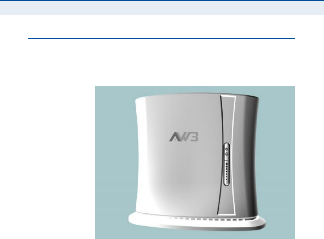
ÎÙíðð ØßÎÜÉßÎÛ ÜÛÍÝÎ×ÐÌ×ÑÒ
The front of the RG300 provides an array of system status indicators. The
back includes four LAN ports for 10/100 Mbps Ethernet connections, two
RJ-11 VoIP phone ports, and a DC power jack.
Figure 1: Front of the RG300
É×óÚ× ÑÐÌ×ÑÒ The RG300 includes an 802.11b/g/n Wi-Fi support. This unit includes
internal antennas for local wireless connections to PCs.

Ý
ØßÐÌÛÎ
ï
| Introduction
RG300 Hardware Description
16
ÐÑÉÛÎ ÍÌßÌËÍ ÔÛÜ The RG300 includes a Power LED indicator that simplifies installation and
WiMAX network troubleshooting. The LED, which is located on the front
panel, is described in the following table.
Figure 2: RG300 LED Indicators
Table 1: Power Status LED
Status Description
On GreenThe unit has completed entry to a WiMAX network.
On AmberIndicates one of the following conditions:
After power on, indicates the unit is running its self test.
Indicates that the network entry process is in progress or has
restarted.
On RedA system failure has occured.
OffNo power is being supplied to the unit.
Power Status LED
Wi-Fi Status LED
WiMAX Signal LEDs

Ý
ØßÐÌÛÎ
ï
| Introduction
RG300 Hardware Description
17
É×óÚ× ÍÌßÌËÍ ÔÛÜ The RG300 includes a Wi-Fi LED indicator that displays the Wi-Fi network
status. The LED, which is located on the front panel, is described in the
following table.
É×ÓßÈ Í×ÙÒßÔ ÔÛÜÍThe RG300 includes seven WiMAX signal strength LED indicators that
display the current WiMAX receive signal status. The LEDs, which are
located on the front panel, are described in the following table.
ÔßÒ ÐÑÎÌÍ The RG300 provides up to four 10BASE-T/100BASE-TX RJ-45 ports. The
LAN ports are standard RJ-45 Ethernet network ports that connect directly
to a PC. They can also be connected to an Ethernet switch or hub to
support more users.
The RJ-45 ports support automatic MDI/MDI-X operation, so you can use
straight-through cables for all network connections to PCs or servers, or to
other switches or hubs. The port supports auto-negotiation, so the
optimum transmission mode (half or full duplex), and data rate (10 or
100Mbps) is selected automatically.
Table 2: Wi-Fi Status LED
Status Description
On GreenThe Wi-Fi radio is enabled and operating normally.
Flashing GreenIndicates data traffic in the Wi-Fi network.
OffThere is no Wi-Fi connection or the radio is disabled.
Table 3: WiMAX Signal Status LEDs
LED Status Description
1 On BlueIndicates the receive signal is 5 dB or more.
2 On BlueIndicates the receive signal is 8 dB or more.
3 On BlueIndicates the receive signal is 12 dB or more.
4 On BlueIndicates the receive signal is 15 dB or more.
5 On BlueIndicates the receive signal is 18 dB or more.
6 On BlueIndicates the receive signal is 20 dB or more.
7 On BlueIndicates the receive signal is 25 dB or more.
1-7 in sequenceOn BlueThe unit is scanning frequency channels.
All 7 LEDsOffNo power is being supplied to the unit.
Ý
ØßÐÌÛÎ
ï
| Introduction
RG300 Hardware Description
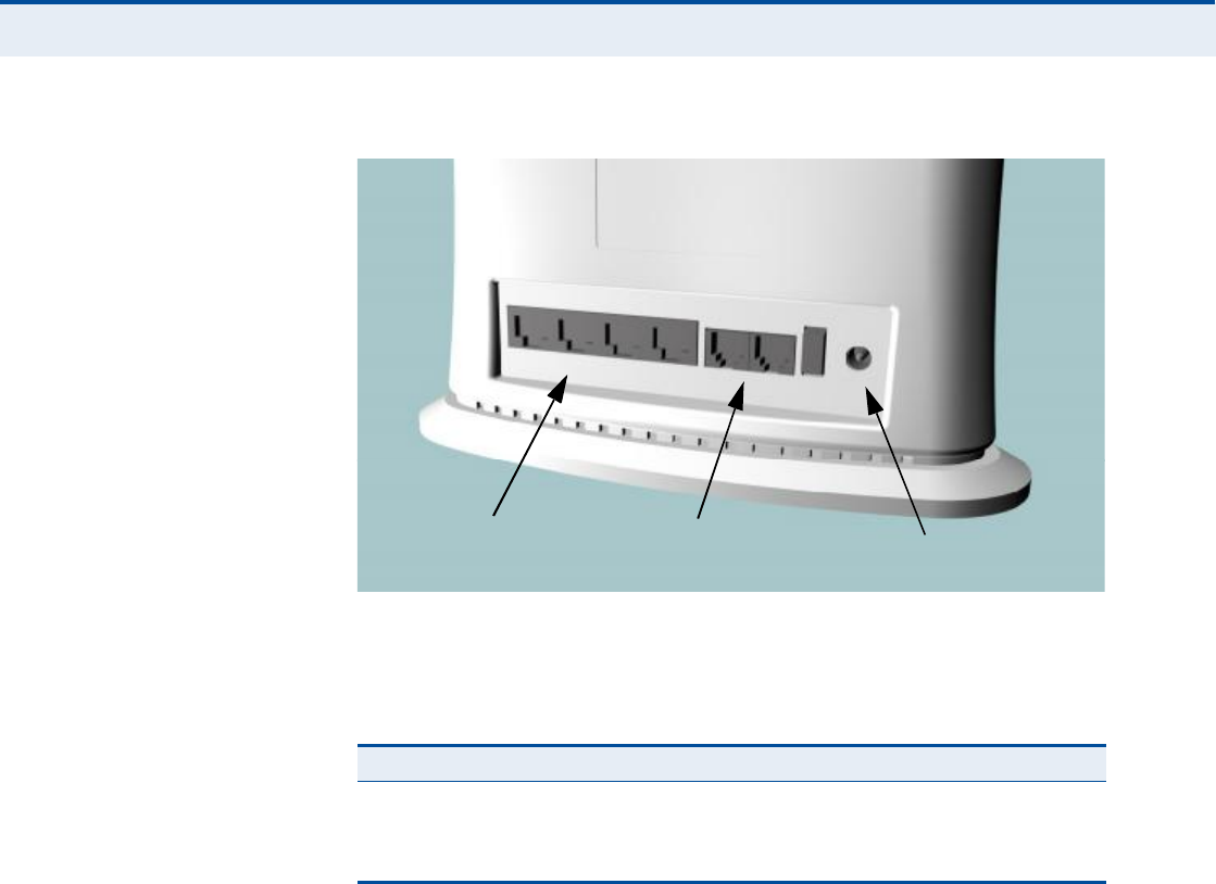
18
Figure 3: Back of the RG300
The RJ-45 ports include a built-in LED status indicator. This LED indicator is
described in the following table.
ÊÑ×Ð ÐØÑÒÛ ÐÑÎÌÍ The RG300 also provides up to two RJ-11 telephone ports that connect
directly to a standard (analog) telephone set. This allows a regular
telephone to be used for making VoIP calls over the Internet.
ÐÑÉÛÎ ßÜßÐÌÛÎ
ÍÑÝÕÛÌ
The power socket is located on the rear panel of the RG300. The power
socket is for the AC power adapter connection.
The unit is powered on when connected to its AC power adapter, and the
power adapter is connected to an AC power source between 100-240 volts
at 50-60Hz.
ÎÛÍÛÌ ÞËÌÌÑÒ The Reset button is located on the base of the RG300 and is used to reset
the unit or restore the factory default configuration. If you press the button
for less than 1 second, the unit will perform a hardware reset. If you press
and hold down the button for 5 seconds or more, any configuration
Table 4: LAN Port Status LED
LED Status Description
Link/ActivityOn GreenEthernet port has a valid link with an attached device.
Flashing GreenThe port is transmitting or receiving data.
OffEthernet port has no link with another device.
RJ-45 LAN Ports
(includes Link/Activity LED) VoIP Phone Ports Power Socket

Ý
ØßÐÌÛÎ
ï
| Introduction
RG300 Hardware Description
19
changes you may have made are removed, and the factory default
configuration is restored to the unit.
Figure 4: Base of the RG300
Reset Button

20
î×ÒÍÌßÔÔ×ÒÙ ÌØÛ ÎÙíðð
This section describes how to install and connect the RG300 WiMAX
802.16e Indoor Gateway.
ÐßÝÕßÙÛ ÝØÛÝÕÔ×ÍÌ
The RG300 package includes:
RG300 unit (RG300-2.3 or RG300-2.5)
RJ-45 Category 5 network cable
AC power adapter
Quick Installation Guide
User Guide CD
×ÒÍÌßÔÔßÌ×ÑÒ ÑÊÛÎÊ×ÛÉ
Before installing the RG300, verify that you have all the items listed in the
package checklist above. If any of the items are missing or damaged,
contact your local dealer. Also, be sure you have all the necessary tools and
cabling before installing the RG300.
ÍÛÔÛÝÌ ß ÔÑÝßÌ×ÑÒ
The RG300 can be installed indoors on any horizontal surface, such as a
desktop or shelf.
When selecting a suitable location for the device, consider these
guidelines:
Select a cool, dry place, which is out of direct sunlight.
The device should have adequate space (approximately two inches) on
all sides for proper air flow.
The device must be near an AC power outlet that provides 100 to
240V, 50 to 60Hz.

Ý
ØßÐÌÛÎ
î
| Installing the RG300
Cable Connections
21
The device should be accessible for network cabling and allow the
status LED indicators to be clearly visible.
Ò
ÑÌÛ
æ
If the RG300 displays a weak WiMAX receive signal, try moving it to
another location.
ÝßÞÔÛ ÝÑÒÒÛÝÌ×ÑÒÍ
The RG300 is a plug-and-play device, so once it has been connected to
your PC and powered up, it is fully operable.
Functioning as a gateway, the unit routes traffic between a WiMAX service
provider!s base station and PCs or notebooks in the local network.
Figure 5: RG300 Connections
To connect the RG300, follow these steps:
ïò Power on the RG300 by by first connecting the AC power adapter to the
unit!s power socket, and then connecting the adapter to an AC power
source.
Ý
ßËÌ×ÑÒ
æ
Use ONLY the power adapter supplied with the RG300. Otherwise,
the product may be damaged.
Ò±¬»¾±±µ ݱ³°«¬»®
λ¹«´¿® и±²»
ßÝ Ð±©»®ß¼¿°¬»®

Ý
ØßÐÌÛÎ
î
| Installing the RG300
Cable Connections
22
îò Observe the Indicator LEDs. When you power on the RG300, verify that
the Power LED turns on and that the other LED indicators start
functioning as described under "RG300 Hardware Description# on
page15.
íò Connect Category 5 or better Ethernet cables from the RG300!s LAN
ports to the network ports of your PCs. Alternatively, you can connect
the LAN port to an Ethernet switch or other device. Make sure the
length of each cable does not exceed 100 meters (328 ft).
If a PC is powered on, the RJ-45 LAN port LED on the RG300 will turn
on to indicate a valid link.
ìò (Optional) Connect a standard (analog) telephone set to one of the
RG300!s VoIP ports using standard telephone cable with RJ-11 plugs.
The RG300 enables VoIP calls to be made through the unit using a
standard (analog) telephone set connected to the VoIP port, or from
PCs or other network devices connected to the LAN ports. Standard
Session Initiation Protocol (SIP) technology is used to make VoIP calls.
You must access the web interface and configure settings for your SIP
service provider before being able to make VoIP calls.
ëò Use your PC!s web browser to access the unit!s management interface
and run the Setup Wizard to make any configuration changes. For more
information, see Chapter 3, "Initial Configuration.#

23
í×Ò×Ì×ßÔ ÝÑÒÚ×ÙËÎßÌ×ÑÒ
The RG300 initial configuration steps can be made through its web
management interface using the Setup Wizard. It is recommended to make
the initial changes by connecting a PC directly to one of the RG300!s LAN
ports.
ßÝÝÛÍÍ×ÒÙ ÌØÛ ÉÛÞ ÓßÒßÙÛÓÛÒÌ ×ÒÌÛÎÚßÝÛ
The RG300 has a default IP address of 192.168.1.1 and a subnet mask of
255.255.255.0. If your PC is set to have an IP address assigned by DHCP
(Dynamic Host Configuration Protocol), you can connect immediately to the
web management interface. Otherwise, you must first check if your PC!s IP
address is set on the same subnet as the RG300 (that is, the PC!s IP
address starts 192.168.1.x).
Ò
ÑÌÛ
æ
If your RG300 unit is not configured with the standard default IP
address and login Username/Password, use the default values on the label
affixed to the unit.
In the web browser!s address bar, type the default IP address: http://
192.168.1.1.
The web browser displays the RG300!s login page.
Figure 6: Login Page
Logging In Type the default User Name "admin# and Password "admin,#
then click Login. The home page displays.
Ý
ØßÐÌÛÎ
í
| Initial Configuration
Accessing the Web Management Interface
24
Language Selects English or Traditional Chinese as the web interface
language.
Ò
ÑÌÛ
æ
It is recommended that you configure a user password as the first
step under "Administrator Settings# on page32 to control management
access to the unit.
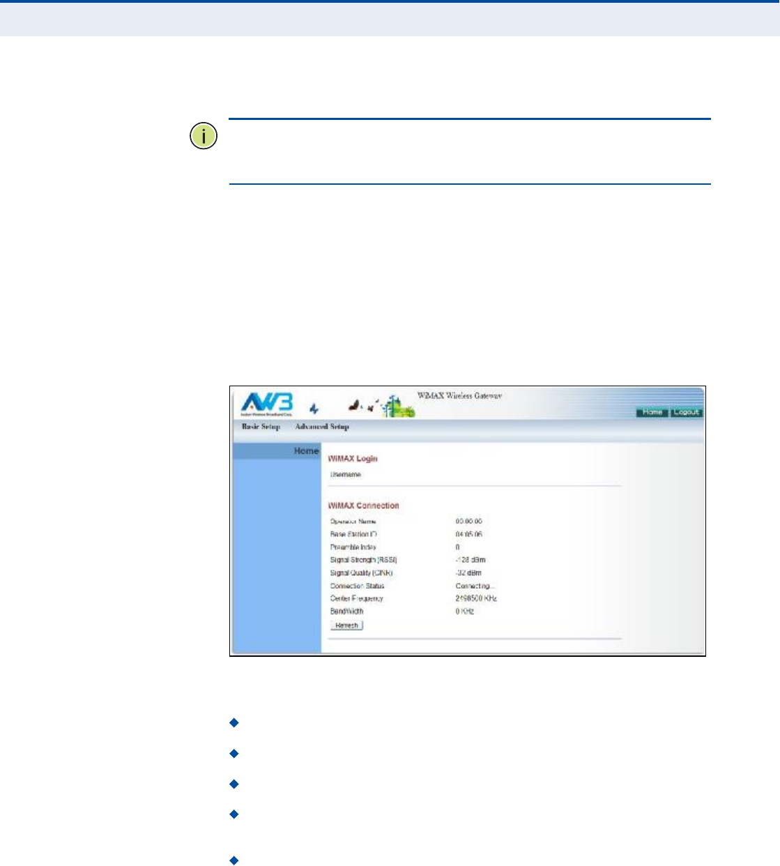
ØÑÓÛ ÐßÙÛ The home page displays the current status of the WiMAX connection.
To configure basic settings for the current operating mode, click Basic
Setup. For more information, see "Using the Basic Setup Wizard# on
page25.
Alternatively, to configure more detailed settings, click Advanced Setup.
For more information, see "The Advanced Setup Menu# on page27.
Figure 7: Home Page
The following parameters are displayed on the home page:
Username Describes the WiMAX network login name.
Operator Name The identity of the operator network.
Base Station ID The identifier of the connected base station.
Preamble Index A number that identifies the sector on the
connected base station.
Signal Strength The current signal strength value of the received
WiMAX radio signal.
Ý
ØßÐÌÛÎ
í
| Initial Configuration
Using the Basic Setup Wizard
25
Signal Quality An indication of the carrier-to-interference-plus-
noise-ratio (CINR), which measures the strength of the receive signal
compared to other interference and noise.
Connection Status The current status of the WiMAX connection.
Central Frequency The center frequency of the WiMAX signal.
Bandwidth The bandwidth of the WiMAX signal.
ËÍ×ÒÙ ÌØÛ ÞßÍ×Ý ÍÛÌËÐ É×ÆßÎÜ
The Basic Setup Wizard takes you through the basic configuration steps for
the RG300.
Launching the Basic Setup Wizard To perform basic configuration,
click Basic Setup on the home page.
When configuring the unit through the Setup Wizard you will need to
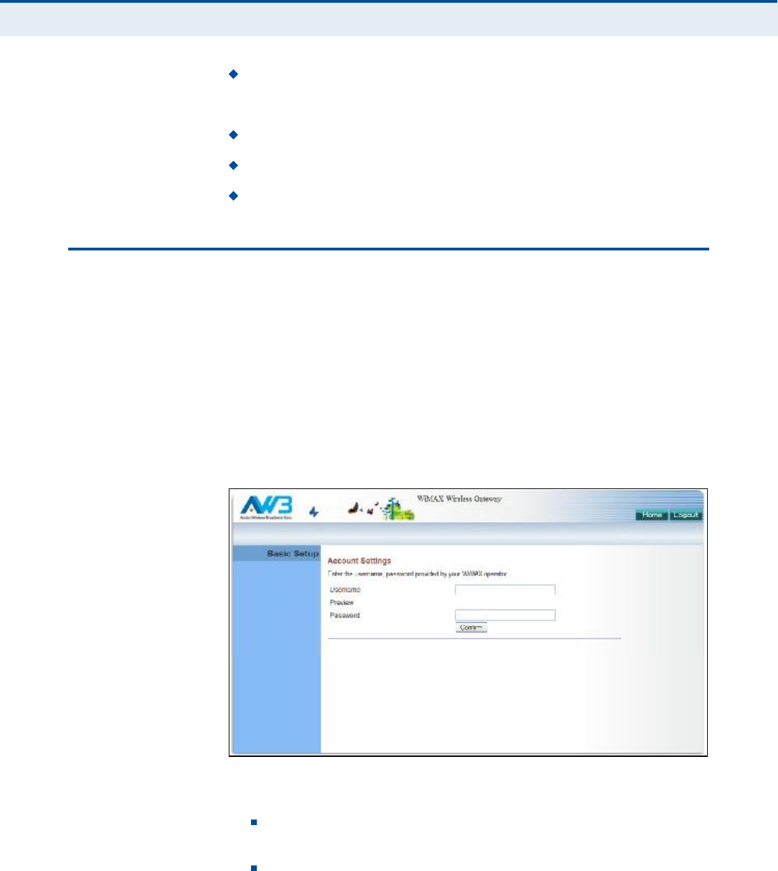
proceed through the following steps:
ïò WiMAX Account Login Configures user authentication settings for
connection to the WiMAX network.
Figure 8: WiMAX Account Login
The following parameters are displayed on this page:
Username The user name required for authentication as
provided by the WiMAX operator.
Preview Displays the current user account that will be used.
Ý
ØßÐÌÛÎ
í
| Initial Configuration
Using the Basic Setup Wizard
26
Password The user password required for authentication as
provided by the WiMAX operator.
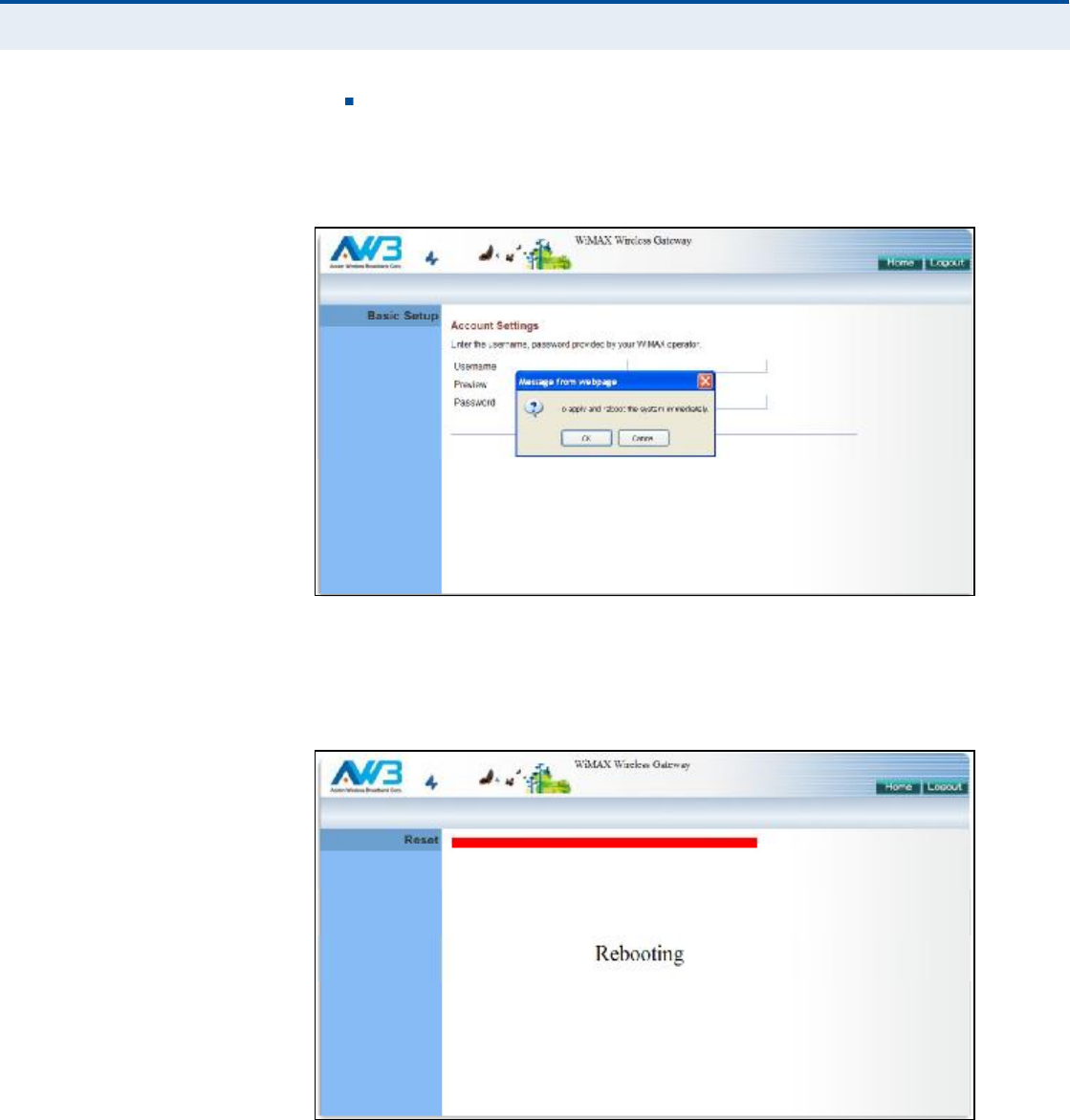
îò Apply Settings Click "Confirm# to apply the basic settings.
Figure 9: Confirm Settings
íò Basic Setup Finished When the Basic Setup steps are completed
the unit reboots and attempts to connect to the specified WiMAX
network. Log in again to return to the Home page.
Figure 10: Setup Wizard Finished

Ý
ØßÐÌÛÎ
í
| Initial Configuration
The Advanced Setup Menu
27
ÌØÛ ßÜÊßÒÝÛÜ ÍÛÌËÐ ÓÛÒË
The Advanced Setup menu provides access to all the configuration settings
available for the RG300.
Figure 11: Advanced Setup
Each primary menu item is sumarized below with links to the relevant
section in this guide where configuration parameters are described in
detail:
System Configures general device settings. See page30.
WAN Configures WAN settings. See page38.
LAN Configures LAN settings. See page44.
NAT Configures Network Address Translation settings. See page47.
Firewall Configures firewall settings. See page52.
Route Configures static routing settings. See page59.
UPnP Enables UPnP. See page62.
VoIP Configures VoIP SIP settings. See page64.
Wi-Fi Configures Wi-Fi settings. See page75.
QoS Configures QoS settings. See page84.
Ý
ØßÐÌÛÎ
í
| Initial Configuration
Common Web Page Buttons
28
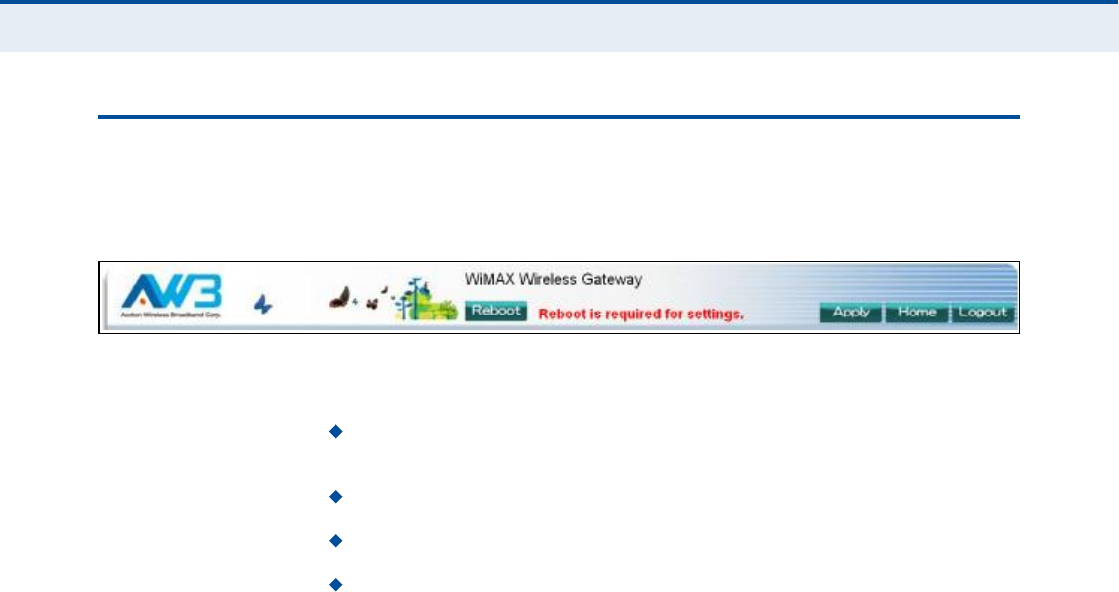
ÝÑÓÓÑÒ ÉÛÞ ÐßÙÛ ÞËÌÌÑÒÍ
The web management interface includes some common buttons that are
displayed at the top of each page.
Figure 12: Common Web Page Buttons
The list below describes these common buttons:
Apply $ Applies all new configuration changes on the current page and
saves them to memory.
Home $ Returns to the web management home page.
Logout $ Immediately closes the current web management session.
Reboot $ The Reboot button appears after some configuration
changes that require the Gateway to be reset. You can make as many
changes as you want before restarting the Gateway. All changes are
saved as they are made, but do not become active until after a restart.
29
Í
ÛÝÌ×ÑÒ
××
ÉÛÞ ÝÑÒÚ×ÙËÎßÌ×ÑÒ
This section provides details on configuring the RG300 using the web
browser interface.
This section includes these chapters:
"System Settings# on page30
"WAN Configuration# on page38
"LAN Configuration# on page44
"NAT Configuration# on page47
"Firewall Configuration# on page52
"Routing Configuration# on page59
"UPnP Configuration# on page62
"VoIP Settings# on page64
"Wi-Fi Settings# on page75
"QoS Configuration# on page84

30
ìÍÇÍÌÛÓ ÍÛÌÌ×ÒÙÍ
The RG300!s System menu allows you to perform general management
functions for the unit, including setting the system time, configuring an
access password, and upgrading the system software.
The System configuration pages include the following options:
"System Status# on page31
"Administrator Settings# on page32
"Firmware Upgrade# on page33
"Configuration Tools# on page34
"System Time# on page35
"System Log# on page36
"Reset# on page37

Ý
ØßÐÌÛÎ
ì
| System Settings
System Status
31
ÍÇÍÌÛÓ ÍÌßÌËÍ
The system status page displays connectivity status information for the
unit!s WiMAX (WAN) and LAN interfaces, and the number of clients
connected to the network.
Figure 13: System Status Internet
Internet Displays WAN (WiMAX) connection status:
WAN IP Displays the IP address assigned by the service provider.
Subnet Mask Displays the WAN subnet mask assigned by the service
provider.
Gateway Displays the WAN gateway address assigned by the service
provider.
Primary DNS Displays the WAN primary DNS address.
Secondary DNS Displays the WAN secondary DNS address.
Connection Type Displays the connection type for the WAN. Either
"fixed# for a static IP setting, or "dhcp# for dynamic IP assignment.
Figure 14: System Status Gateway
Gateway Display system IP settings, DHCP server, and firewall status:
IP Address Displays the unit!s IP address.
Subnet Mask Displays the subnet mask.
DHCP Server Displays the DHCP server status.
Firewall Displays the firewall status.
Ý
ØßÐÌÛÎ
ì
| System Settings
Administrator Settings
32
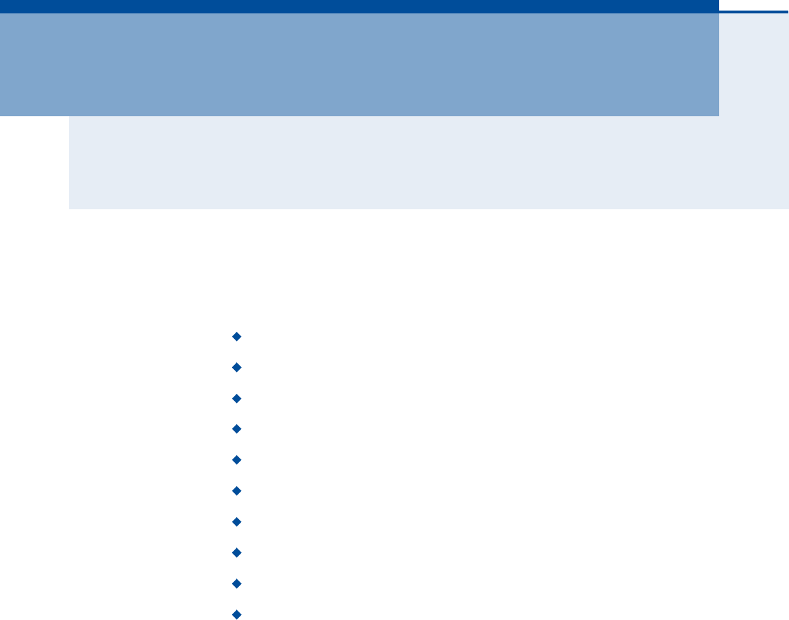
Figure 15: System Status Information
Information Displays the number of connected clients, as well as the
unit!s LAN and WAN MAC addresses:
Connected Clients Displays the number of connected clients, if any.
LAN MAC Address Displays the LAN MAC address.
LAN MTU Size The maximum transmission unit size in bytes.
WAN MAC Address Displays WAN MAC address.
WAN MTU Size The maximum transmission unit size in bytes.
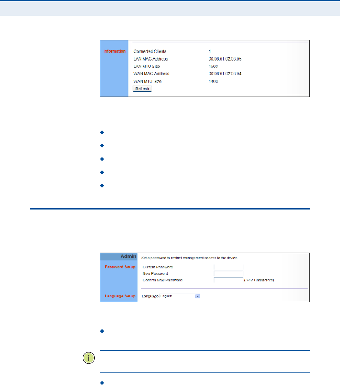
ßÜÓ×Ò×ÍÌÎßÌÑÎ ÍÛÌÌ×ÒÙÍ
The Administrator Settings page enables you to change the password for
management access to the RG300.
Figure 16: Setting a Password
The following parameters are displayed on this page:
Current Password You need to first enter your current administrator
password to be able to configure a new one. (Default: admin)
Ò
ÑÌÛ
æ
If your RG300 unit is not configured with the standard default login
Username/Password, use the default values on the label affixed to the unit.
New Password Enter a new administrator password. (Range: 3~12
characters)
Ý
ØßÐÌÛÎ
ì
| System Settings
Firmware Upgrade
33
Confirm New Password Enter the new password again for
verification. (Range: 3~12 characters)
Language Selects English or Traditional Chinese as the web interface
language.
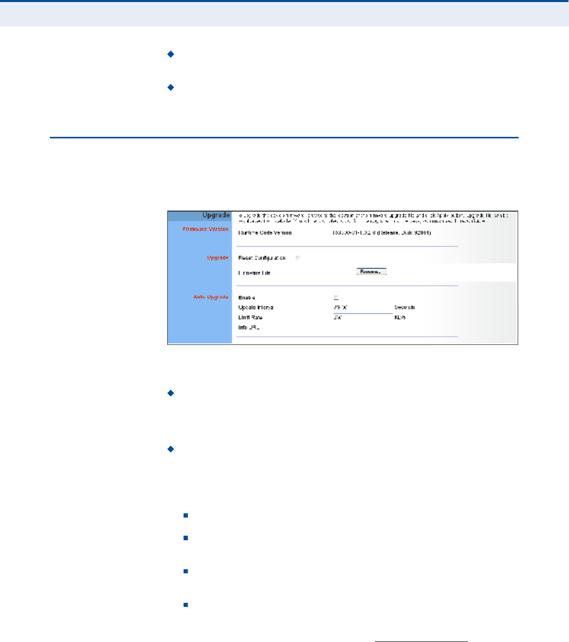
Ú×ÎÓÉßÎÛ ËÐÙÎßÜÛ
The Firmware Upgrade page enables you to download new software to the
unit.
Figure 17: Firmware Upgrade
The following parameters are displayed on this page:
Upgrade Downloads an operation code file from the web
management station to the RG300 using HTTP. Use the Browse button
to locate the code file locally on the management station and check the
Reset Configuration to restore factory defaults. Click Apply to proceed.
Auto Upgrade Provides a method to automatically upgrade the
Gateway when new code is available, as indicated by the contents of an
information file provided by the WiMAX service operator. The Auto
Upgrade information file and code file can be located on the same
server or different servers.
Enable Enables the automatic upgrade feature.
Update Interval A time interval (in seconds) for checking the
Info URL for new software information.
Limit Rate Places a limit on the firmware download rate from the
server.
Info URL A text string that indicates the location of an Auto
Upgrade information file on an FTP server. The file contains
information on the version of software available, and the FTP server
on which it is located. (For example: ftp://192.168.1.16/
autoupgrade/RG300-autoupgrade.info)

Ý
ØßÐÌÛÎ
ì
| System Settings
Configuration Tools
34
ÝÑÒÚ×ÙËÎßÌ×ÑÒ ÌÑÑÔÍ
The Configurations Tools page allows you to restore factory default
settings, or save and restore the unit!s configuration settings to or from a
file on the management station.
Figure 18: Configuration Tools
The following parameters are displayed on this page:
Restore Factory Default Configuration Resets the unit to its
factory default settings. When you select "Restore Factory Default
Configuration# and click Apply, a confirmation page displays. Click OK
to continue.
Backup Settings Saves the current configuration settings to a file on
the web management station.
Restore Settings Restores a saved configuration file to the unit.
Configuration files are plain-text files that can be edited directly to
modify settings (not all parameters need be defined). You can use the
Browse button to locate the file on the web management station.
Fully Restore Settings Restores all settings that are defined in
the uploaded configuration file. Any undefined settings are returned
to factory defaults.
Merge Settings Restores defined settings in the uploaded
configuration file. All other undefined settings are not changed.
Figure 19: Restore Configuration Settings

Ý
ØßÐÌÛÎ
ì
| System Settings
System Time
35
ÍÇÍÌÛÓ Ì×ÓÛ
The RG300 uses the Simple Network Time Protocol (SNTP) to set its
internal clock based on periodic updates from a time server. Maintaining an
accurate time on the device enables the system log to record meaningful
dates and times for event entries.
SNTP uses Coordinated Universal Time (or UTC, formerly Greenwich Mean
Time, or GMT) based on the time at the Earth!s prime meridian, zero
degrees longitude. To display a time corresponding to your local time, you
must select your time zone.
Figure 20: System Time
The following parameters are displayed on this page:
Enable Enables the unit to set its internal clock based on periodic
updates from a time server. The unit acts as an SNTP client, periodically
sending time synchronization requests to a specified time server.
Alternatively, you can select "None# and set the time and date
manually.
Time Server Address The IP address of a time server that the unit
attempts to poll for a time update.
Current Time (hh:mm:ss) The current time of the system clock.
New Time (hh:mm:ss) Sets the system clock to the time specified.
Sync with host Sets the unit!s time from the web management PC!s
system time.
Current Date (yyyy:mm:dd) The current date of the system clock.
New Date (yyyy:mm:dd) Sets the system clock date.
Set Time Zone SNTP uses Coordinated Universal Time (or UTC,
formerly Greenwich Mean Time, or GMT) based on the time at the
Earth!s prime meridian, zero degrees longitude. To display a time
corresponding to your local time, you must select your time zone from
the pull-down list.
Ý
ØßÐÌÛÎ
ì
| System Settings
System Log
36
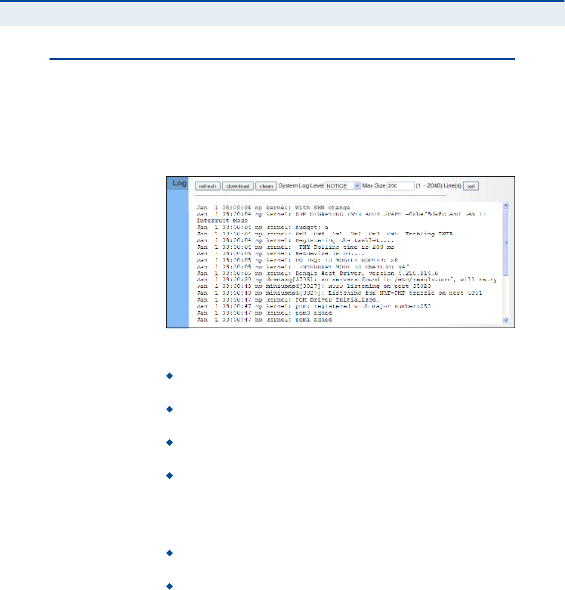
ÍÇÍÌÛÓ ÔÑÙ
The RG300 supports a logging process that controls error messages saved
to memory. The logged messages serve as a valuable tool for isolating
device and network problems. The System Log page displays the latest
messages logged in chronological order, from the oldest to the newest. Log
messages saved in the unit!s memory are erased when the device is
rebooted.
Figure 21: System Log
The following items are displayed on this page:
Refresh $ Sends a request to add the latest entries to the System Log
Table.
Download $ Downloads the current system log messages to a file on
the web management station.
Clean $ Removes all the current system log messages from the
System Log Table.
System Log Level $ Sets the minimum severity level for event
logging. The system allows you to limit the messages that are logged
by specifying a minimum severity level. Error message levels range
from the most severe (Emergency) to least severe (Debug). The
message levels that are logged include the specified minimum level up
to the Emergency level.
Max Size $ The maximum memory size to be used for log messages
on the Gateway. (Range: 1-512 KB)
Set $ Click to set the Max Size and System Log Level values.
Ý
ØßÐÌÛÎ
ì
| System Settings
Reset
37
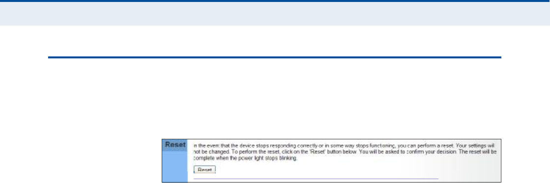
ÎÛÍÛÌ
The Reset page allows you to restart the device!s software. If the unit stops
responding correctly or in some way stops functioning, performing a reset
can clear the condition.
Figure 22: Reset Unit
Reset Resets the unit. All current settings are retained.

38
ëÉßÒ ÝÑÒÚ×ÙËÎßÌ×ÑÒ
The information in this chapter covers the configuration options for the
RG300!s WAN connection.
The WAN configuration pages include the following options:
"WAN Settings# on page39
"DNS# on page42
"DDNS# on page43

Ý
ØßÐÌÛÎ
ë
| WAN Configuration
WAN Settings
39
ÉßÒ ÍÛÌÌ×ÒÙÍ
Select the WAN connection type used by your service provider and specify
DNS (Domain Name System) servers.
Figure 23: WAN Settings
The unit can be connected to your ISP in one of the following ways:
DHCP IP Address Selects configuration for an Internet connection
using DHCP for IP address assignment.
Static IP Address Selects configuration for an Internet connection
using a fixed IP assignment.
Retries The maximum number of times the Gateway sends a DHCP
request to a DHCP server. (Range: 1-10000)
Timeout The maximum time period (in seconds) the Gateway waits
for a response from a DHCP server before it resends a request.
(Range: 1-3600 seconds)
L2TP Selects configuration for an Internet connection using the Layer
2 Tunneling Protocol, an access protocol often used for virtual private
networks.
PPTP Selects configuration for an Internet connection using the
Point-to-Point Tunneling Protocol, an access protocol often used for
virtual private networks.
Ò
ÑÌÛ
æ
For the Dynamic IP Address (DHCP) option, the unit requires no
further configuration. Selecting other WAN types displays the parameters
that are required for configuring the connection.

Ý
ØßÐÌÛÎ
ë
| WAN Configuration
WAN Settings
40
ÜÇÒßÓ×Ý ×Ð ßÜÜÎÛÍÍ For dynamic IP assignment from the service provider, the unit functions as
a Dynamic Host Configuration Protocol (DHCP) client. When enabled, no
other settings are required.
Figure 24: Dynamic IP Address
ÍÌßÌ×Ý ×Ð ÍÛÌÌ×ÒÙÍ Selecting Static IP Address for the WAN type enables you to enter static IP
settings as assigned by the service provider.
Figure 25: Static IP Settings
The following parameters are displayed in this section on this page:
IP Address The IP address provided by your service provider. Valid
IP addresses consist of four decimal numbers, 0 to 255, separated by
periods.
Netmask Indicates the subnet mask, such as 255.255.255.0.
Gateway The gateway IP address provided by your service provider.
Ý
ØßÐÌÛÎ
ë
| WAN Configuration
WAN Settings
41
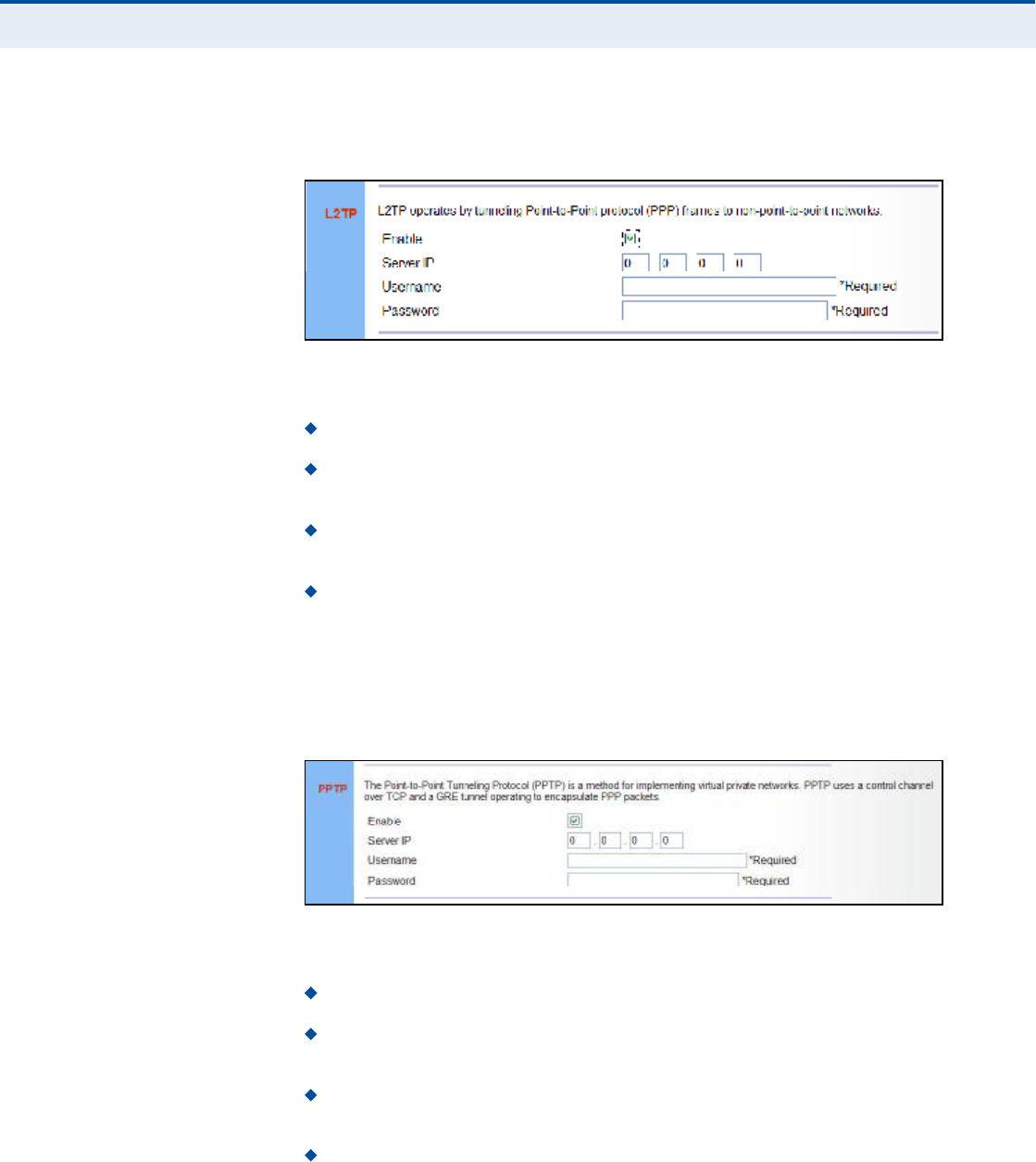
ÔîÌÐ ÍÛÌÌ×ÒÙÍ If your service provider supports Layer 2 Tunneling Protocol (L2TP) for your
Internet connection, configure the settings described below.
Figure 26: L2TP Settings
The following parameters are displayed in this section on this page:
Enable Enables the L2TP settings.
Server IP The IP address of the L2TP server, as specified by the
service provider.
Username Enter your user name for connecting to the L2TP service,
as supplied by the service provider. (Range: 1-20 characters)
Password Specify the password for your connection, as supplied by
the service provider. (Range: 1-20 characters)
ÐÐÌÐ ÍÛÌÌ×ÒÙÍ If your service provider supports Point-to-Point Tunneling Protocol (PPTP)
for your Internet connection, configure the settings described below.
Figure 27: PPTP Settings
The following parameters are displayed in this section on this page:
Enable Enables the PPTP settings.
Server IP The IP address of the PPTP server, as specified by the
service provider.
Username Enter your user name for connecting to the PPTP service,
as supplied by the service provider. (Range: 1-20 characters)
Password Specify the password for your PPTP connection, as
supplied by the service provider. (Range: 1-20 characters)

Ý
ØßÐÌÛÎ
ë
| WAN Configuration
DNS
42
ÜÒÍ
DNS (Domain Name System) server addresses are usually provided by
service providers, however if you want to specify certain servers, the DNS
page enables you to enter primary and secodary DNS addresses.
Figure 28: DNS Settings
The following parameters are displayed on this page:
Primary DNS Address Address of the primary DNS server, specified
in the form of 0.0.0.0. (The address 0.0.0.0 disables the manual DNS
setting.)
Secondary DNS Address (optional) Optional address of a
secondary DNS server, specified in the form of 0.0.0.0.

Ý
ØßÐÌÛÎ
ë
| WAN Configuration
DDNS
43
ÜÜÒÍ
Dynamic DNS (DDNS) provides users on the Internet with a method to tie
a specific domain name to the unit!s dynamically assigned IP address.
DDNS allows your domain name to follow your IP address automatically by
changing your DNS records when your IP address changes.
The RG300 provides access to a number DDNS service providers, such as
DynDns.org, Easydns.com, and ZoneEdit.com. To set up an DDNS account,
visit the website of one of the supported service providers.
Figure 29: DDNS Settings
The following items are displayed in this section on this page:
Enable $ Enables the DDNS service.
Max Time Interval $ The maximum time period before the Gateway
sends an update to the DDNS provider. (Options: 1hr, 3hr, 6hr, 8hr,
12hr, 1day, 3days, 1week)
DDNS Server $ Specifies the DDNS service provider, DynDns.org,
Freedns.afraid.org, ZoneEdit.com or Non-IP.com.
Host Name $ Specifies the URL of the DDNS service.
User Name ! Specifies your user name for the DDNS service.
Password $ Specifies your password for the DDNS service.

44
êÔßÒ ÝÑÒÚ×ÙËÎßÌ×ÑÒ
The information in this chapter covers the configuration options for the
RG300!s LAN functions.
The LAN configuration pages include the following options:
"LAN Settings# on page45
"DHCP Client List# on page46
Ý
ØßÐÌÛÎ
ê
| LAN Configuration
LAN Settings
45
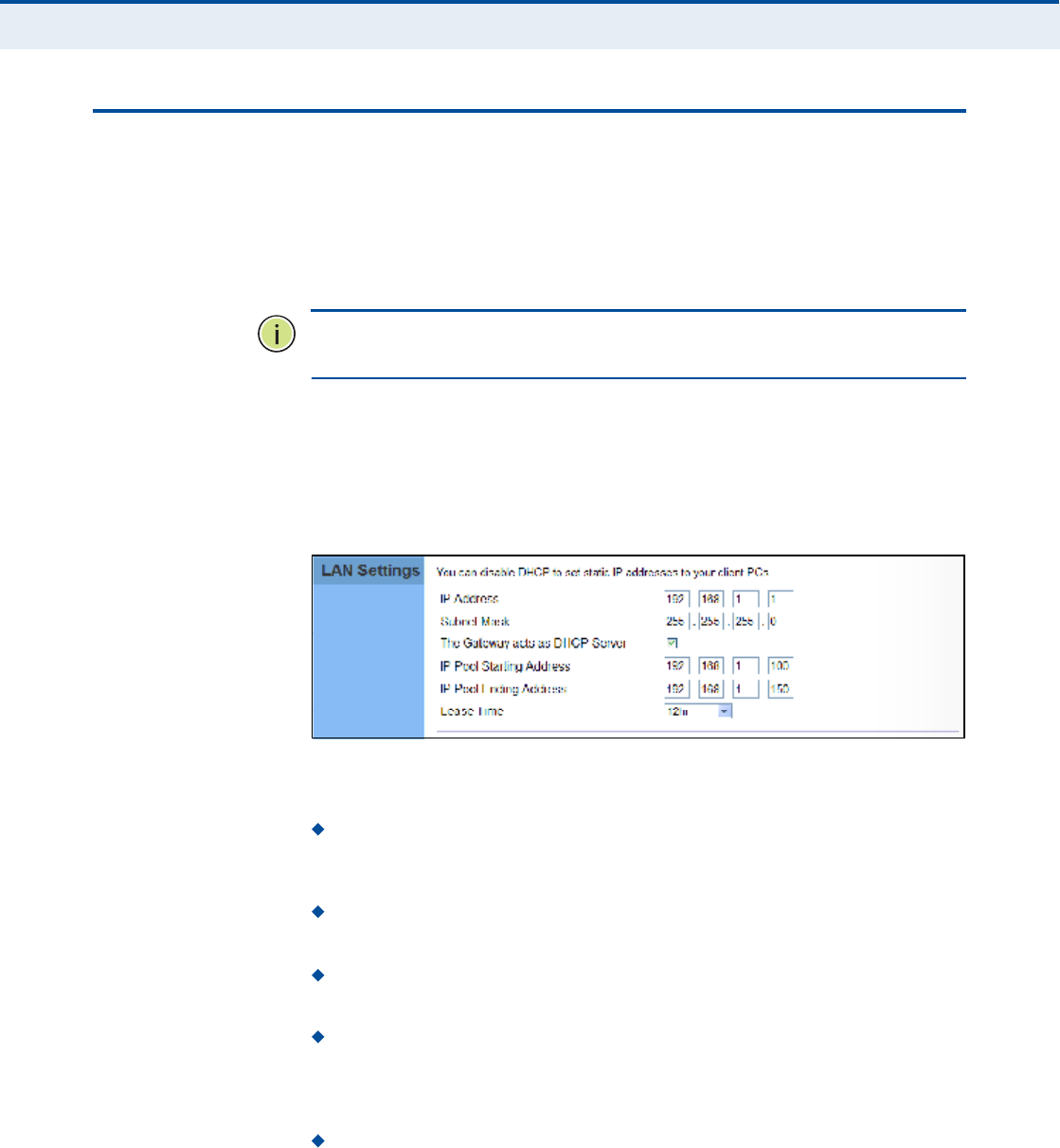
ÔßÒ ÍÛÌÌ×ÒÙÍ
The RG300 must have a valid IP address for management using a web
browser and to support other features. The unit has a standard default IP
address of 192.168.1.1. You can use this IP address or assign another
address that is compatible with your existing local network. The unit can
also be enabled as a Dynamic Host Configuration Protocol (DHCP) server to
allocate IP addresses to local PCs.
Ò
ÑÌÛ
æ
If your RG300 unit is not configured with the standard default IP
address, use the default value on the label affixed to the unit.
The RG300 includes a DHCP server that can assign temporary IP addresses
to any attached host requesting the service. Addresses are assigned to
clients from a common address pool configured on the unit. Configure an
address pool by specifying start and end IP addresses. Be sure not to
include the unit's IP address in the address pool range.
Figure 30: LAN Settings
The following parameters are displayed on this page:
IP Address The IP address of the unit. Valid IP addresses consist of
four decimal numbers, 0 to 255, separated by periods. The standard
default setting is 192.168.1.1.
Subnet Mask Indicates the local IP subnet mask. The default setting
is 255.255.255.0.
The Gateway acts as DHCP Server Check this box to enable the
DHCP server.
IP Pool Starting/Ending Address Specifies the start and end IP
address of a range that the DHCP server can allocate to DHCP clients.
You can specify a single address or an address range. Note that the
address pool range must be in the same subnet as the unit!s IP setting.
Lease Time Selects a time limit for the use of an IP address form the
IP pool. When the time limit expires, the client has to request a new IP
address. (Options: 1hr, 3hr, 6hr, 8hr, 12hr, 1 day, 3days, 1 week)
Ý
ØßÐÌÛÎ
ê
| LAN Configuration
DHCP Client List
46
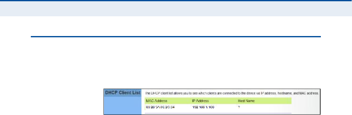
ÜØÝÐ ÝÔ×ÛÒÌ Ô×ÍÌ
The DHCP Client List page enables you to see the MAC address of devices
that are currently connected to the unit and have been assigned an IP
address by the DHCP server.
Figure 31: DHCP Client List

47
éÒßÌ ÝÑÒÚ×ÙËÎßÌ×ÑÒ
The information in this chapter covers the configuration options for the
RG300!s Network Address Translation (NAT) functions.
The NAT configuration pages include the following options:
"NAT Settings# on page48
"Port Mapping# on page49
"DMZ# on page50
"ALG# on page51
Ý
ØßÐÌÛÎ
é
| NAT Configuration
NAT Settings
48
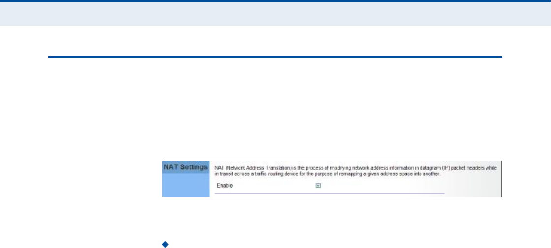
ÒßÌ ÍÛÌÌ×ÒÙÍ
Network Address Translation (NAT) is a standard method of mapping
multiple "internal# IP addresses to one "external# IP address on devices at
the edge of a network. For the RG300, the internal (local) IP addresses are
the IP addresses assigned to local PCs by the DHCP server, and the
external IP address is the IP address assigned to the WiMAX interface.
Figure 32: NAT Settings
The following item is displayed on this page:
Enable Enables NAT on the device.

Ý
ØßÐÌÛÎ
é
| NAT Configuration
Port Mapping
49
ÐÑÎÌ ÓßÐÐ×ÒÙ
Using the NAT Port Mapping feature, remote users can access different
servers on your local network using your single public IP address.
Remote users accessing services such as web or FTP at your local site
thorugh your public IP address, are redirected (mapped) to other local
server IP addresses and TCP/UDP port numbers. For example, if you set
Type/Public Port to TCP/80 (HTTP or web) and the Private IP/Port to
192.168.7.9/80, then all HTTP requests from outside users forwarded to
192.168.7.9 on port 80. Therefore, by just using your external IP address
provided by your ISP, Internet users can access the services they need at
the local addresses to which you redirect them.
The more common TCP service port numbers include: HTTP: 80, FTP: 21,
Telnet: 23, and SSH: 22.
Figure 33: Port Mapping
The following parameters are displayed on this page:
Private IP The IP address of the server on the local Ethernet
network. The specified address must be in the same subnet as the
RG300 and its DHCP server address pool. Alternatively, the IP address
can be set by selecting a PC from the DHCP client list.
Use Client List Allows the Private IP to be selected from the DHCP
client list.
Private Port Specifies the TCP/UDP port number used on the local
server for the service. (Range: 1-65535)
Public Port Specifies the public TCP/UDP port used for the service on
the WAN interface. (Range: 1-65535)
Services Specifies port numbers for some of the more common
services. (Options: FTP, SSH, Telnet, SMTP, HTTP, HTTPS)
Comment A text comment for the forwarding rule.
Add Rules Adds the defined rule to the port forwarding table. Use
the Delete button next to a rule to remove it from the table.

Ý
ØßÐÌÛÎ
é
| NAT Configuration
DMZ
50
ÜÓÆ
If you have a client PC that cannot run an Internet application properly
from behind the NAT firewall, you can open the client up to unrestricted
two-way internet access by defining a virtual-DMZ (virtual-demilitarized-
zone) host.
Figure 34: DMZ Settings
The following parameters are displayed on this page:
Enable Enables the feature.
DMZ Host Specifies the IP address of the virtual DMZ host.
Alternatively, the host IP can be set by selecting a PC from the DHCP
client list.
Use Client List Allows the host IP to be selected from the DHCP
client list.
Ò
ÑÌÛ
æ
Adding a host to the DMZ may expose your local network to a
variety of security risks, so only use this option as a last resort.

Ý
ØßÐÌÛÎ
é
| NAT Configuration
ALG
51
ßÔÙ
The RG300 supports the passthrough of three of the most commonly used
VPN protocols; PPTP, L2TP, and IPsec, as well as VoIP SIP traffic. The VPN
protocols allow remote users to establish a secure connection to their
corporate network. If your service provider supports VPNs, then these
protocols can be used to create an authenticated and encrypted tunnel for
passing secure data over the Internet (that is, a traditionally shared data
network).
Figure 35: ALG Settings
The following items are displayed on this page:
SIP ALG Enable $ Enables the passthrough of VoIP SIP traffic on the
configured server port numbers.
SIP Server Ports $ Lists the SIP server ports used for VoIP traffic.
Port Number $ Adds a new SIP Server port number.
PPTP Passthrough ! PPTP (Point-to-Point Tunneling Protocol)
provides a secure tunnel for remote client access to a PPTP security
gateway. PPTP includes provisions for call origination and flow control
required by ISPs.
L2TP IPsec Passthrough ! L2TP (Layer 2 Tunneling Protocol)
merges the best features of PPTP and the Layer 2 Forwarding (L2F)
protocol. Like PPTP, L2TP requires that the ISP!s routers support the
protocol. IPsec (Internet Protocol Security) encrypts and authenticates
entire IP packets and encapsulates them into new IP packets for secure
communications between networks.

52
èÚ×ÎÛÉßÔÔ ÝÑÒÚ×ÙËÎßÌ×ÑÒ
The information in this chapter covers the configuration options for the
RG300!s firewall functions.
The Firewall configuration pages include the following options:
"Firewall Settings# on page53
"Client Filtering# on page54
"Port Filtering# on page55
"MAC Filtering# on page56
"URL Filtering# on page57
"Host Filtering# on page58
Ý
ØßÐÌÛÎ
è
| Firewall Configuration
Firewall Settings
53
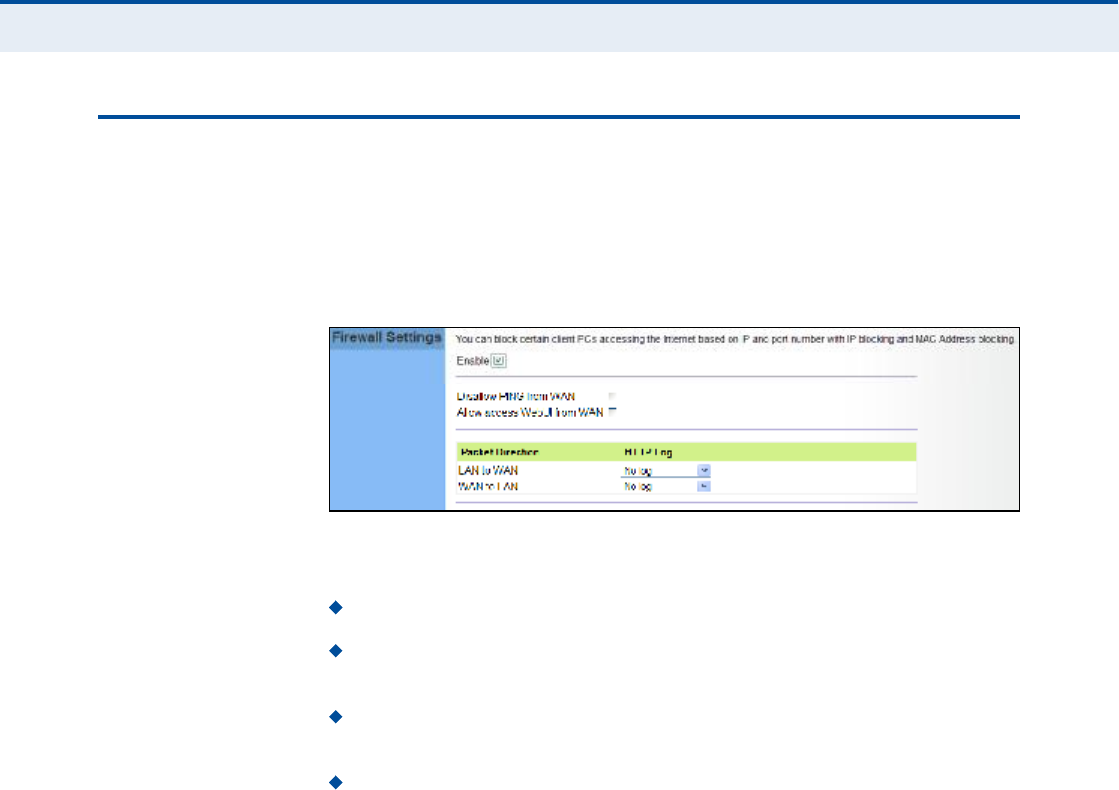
Ú×ÎÛÉßÔÔ ÍÛÌÌ×ÒÙÍ
The RG300 provides extensive firewall protection by restricting connection
parameters to limit the risk of intrusion and defending against a wide array
of common hacker attacks. You can also block access to the Internet from
clients on the local network based on IP addresses and TCP/UDP port
numbers, or specific MAC addresses.
Figure 36: Firewall Settings
The following parameters are displayed on this page:
Enable Enables all firewall features.
Disallow PING from WAN side Prevents pings on the unit!s WiMAX
interface from being routed to the network.
Allow Access WebUI from WAN Allows a user to be able to log into
the Gateway web interface from a remote location.
HTTP Log Enables LAN-to-WAN and WAN-to-LAN HTTP traffic to be
logged. The logged information can be viewed on the system log page.
Ý
ØßÐÌÛÎ
è
| Firewall Configuration
Client Filtering
54
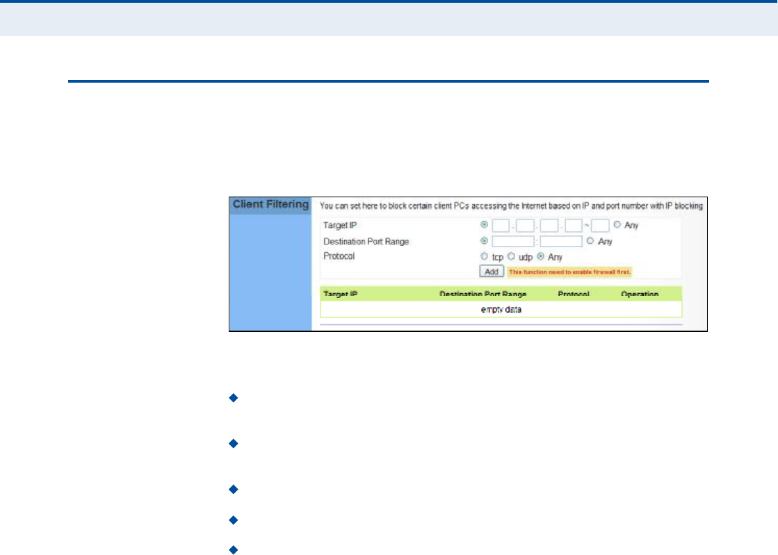
ÝÔ×ÛÒÌ Ú×ÔÌÛÎ×ÒÙ
You can block access to the Internet from clients on the local network by
specifying IP addresses and TCP/UDP port numbers. You can configure up
to five IP filters on the unit.
Figure 37: Client Filtering Settings
The following parameters are displayed on this page:
Target IP Specifies an IP address or range on the local network to
filter.
Destination Port Range Specifies a TCP/UDP port number range to
filter. (Range: 1-65535 or Any)
Protocol Specifies the the port type. (Options: TCP, UDP, Any)
Add Adds a new IP address to the filter table.
Remove Removes an IP address from the filter table.
Ý
ØßÐÌÛÎ
è
| Firewall Configuration
Port Filtering
55
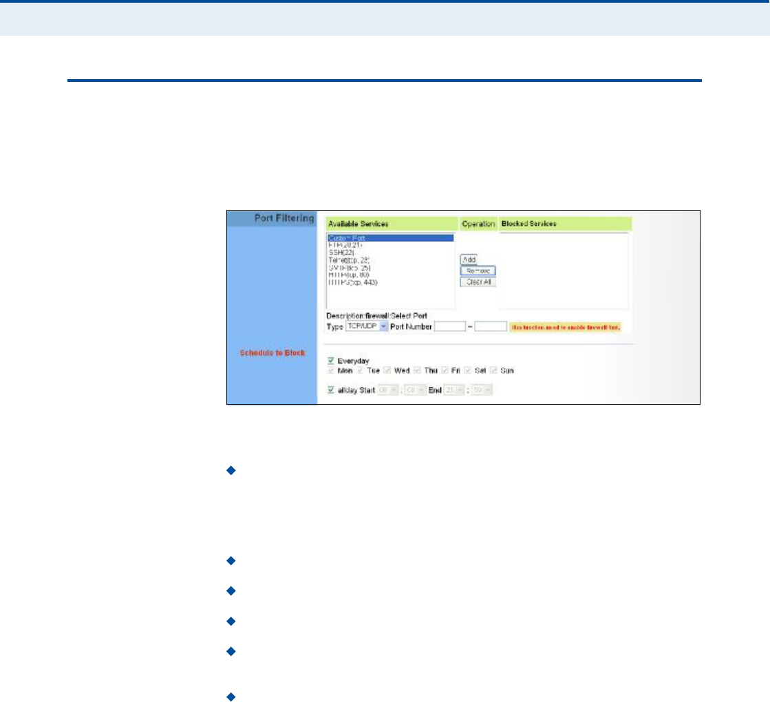
ÐÑÎÌ Ú×ÔÌÛÎ×ÒÙ
Port filtering restricts connections to limit the risk of intrusion and can
defend against a wide array of common hacker attacks. The port filtering
feature allows the Gateway to block traffic for a specified schedule based
on TCP/UDP ports.
Figure 38: Port Filtering
The following items are displayed on this page:
Available Services $ The TCP/UDP services allowed access to the
Gateway. All TCP/UDP ports are open unless specified as blocked. Some
common protocols are pre-defined and can be selected to "Add# to the
Blocked Services. Select "Custom Port# to define other TCP/UDP port
ranges to block.
Operation $ Adds, removes, or clears all blocked services.
Blocked Services $ Lists the TCP/UDP ports that are blocked
Type $ Specifies the port type, TCP, UDP, or TCP/UDP.
Port Number $ Specifies a custom-defined range of TCP/UDP ports to
block.
Schedule to Block $ Configures the days of the week and times to
block the defined traffic.
Ý
ØßÐÌÛÎ
è
| Firewall Configuration
MAC Filtering
56
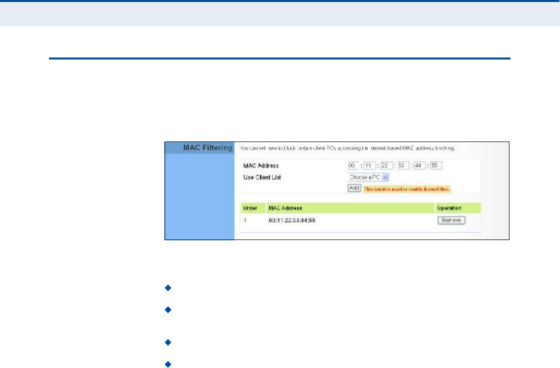
ÓßÝ Ú×ÔÌÛÎ×ÒÙ
You can block access to the Internet from clients on the local network
based on MAC addresses. You can configure up to 20 MAC address filters
on the unit.
Figure 39: MAC Filtering
The following parameters are displayed on this page:
MAC Address Specifies a local PC MAC address.
Use Client List Selects a local PC MAC address from the Gateway!s
DHCP client list table.
Add Adds a new MAC address to the filter table.
Remove Removes a MAC address from the filter table.
Ý
ØßÐÌÛÎ
è
| Firewall Configuration
URL Filtering
57
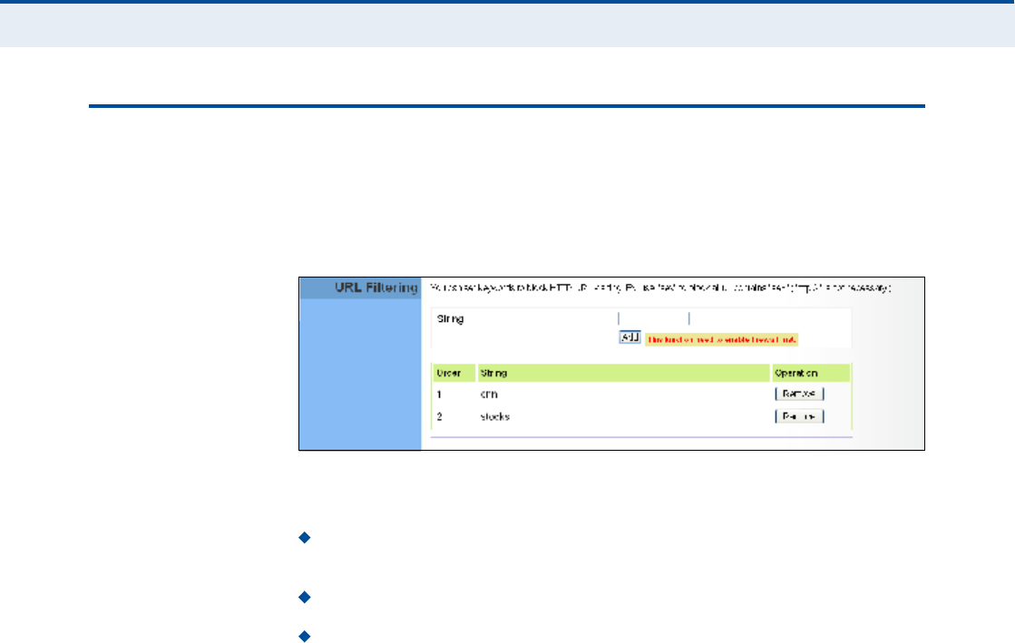
ËÎÔ Ú×ÔÌÛÎ×ÒÙ
The RG300 provides a method for blocking Internet access based on
Uniform Resource Locator (URL) keywords. By filtering URLs accessed from
the network, users can be prevented from reaching prohibited online
content.
Figure 40: URL Filtering
The following items are displayed on this page:
String $ Specifies text keyword contained in URLs that will be filtered.
(Maximum 256 characters; invalid characters [% " & ' # \].)
Add $ Adds a keyword string to the URL filter.
Remove Removes an entry from the filter table.
Ý
ØßÐÌÛÎ
è
| Firewall Configuration
Host Filtering
58
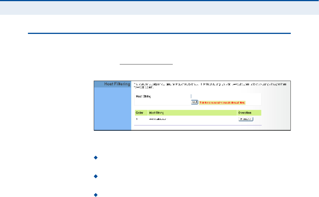
ØÑÍÌ Ú×ÔÌÛÎ×ÒÙ
The RG300 provides a method for blocking Internet access based on web
domains. A domain name is the name of a particular web site. For
example, www.fungames.com.
Figure 41: Host Filtering
The following items are displayed on this page:
Host String $ Displays current Host filter. (Maximum 256 characters;
invalid characters [% " & ' # \].)
Add $ Enters a domain name keyword for a host filtering. For
example, myhost.example.com.
Remove $ Removes an entry from the filter table.

59
çÎÑËÌ×ÒÙ ÝÑÒÚ×ÙËÎßÌ×ÑÒ
The information in this chapter covers the configuration options for the
RG300!s Routing functions.
The Routing configuration pages include the following options:
"Routing Table# on page60
"Static Route# on page61

Ý
ØßÐÌÛÎ
ç
| Routing Configuration
Routing Table
60
ÎÑËÌ×ÒÙ ÌßÞÔÛ
The
Routing Table displays the list of static routes on the unit.
Figure 42: Routing Table
The following parameters are displayed in this section on this page:
Route The IP address that identifies the IP subnet of the remote
network.
Gateway The IP address of the router within the local IP subnet that
forwards traffic to the remote IP subnet.
Netmask The mask that identifies the IP subnet of the remote
network.
Interface Indicates the local network interface on the unit.
Ý
ØßÐÌÛÎ
ç
| Routing Configuration
Static Route
61
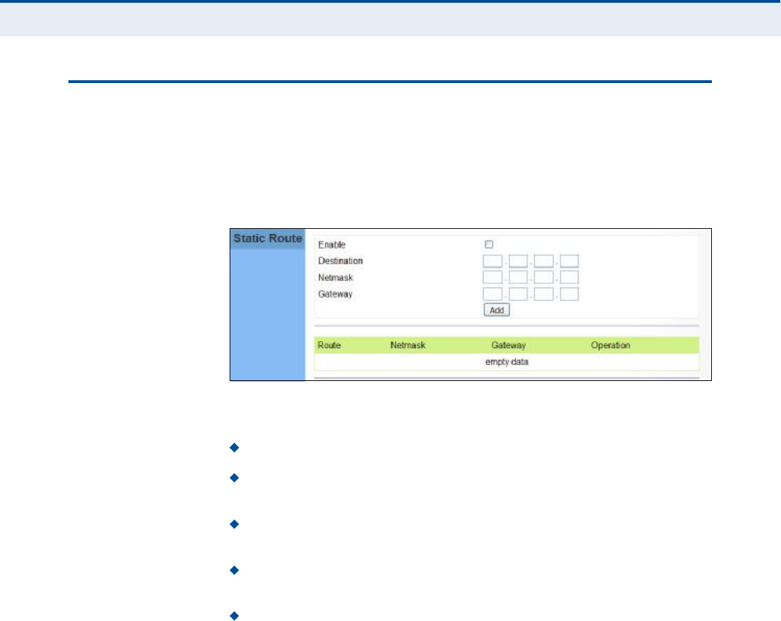
ÍÌßÌ×Ý ÎÑËÌÛ
Static routes allow a manual method to set up routing between specific
destination networks, subnetworks, or hosts. Static routes may be required
to force the use of a specific route to a subnet. Static routes do not
automatically change in response to changes in network topology, so only
configure a small number of stable routes to ensure network accessibility.
Figure 43: Static Route
The following items are displayed on this page:
Enable $ Enables the configured routes in the Static Route table.
Destination $ A destination network or specific host to which packets
can be routed.
Netmask $ Network mask for the associated IP subnet. This mask
identifies the host address bits used for routing to specific subnets.
Gateway $ The IP address of the router at the next hop to which
matching frames are forwarded.
Add $ Adds a new route to the table.

62
ïð ËÐÒÐ ÝÑÒÚ×ÙËÎßÌ×ÑÒ
The information in this chapter covers the configuration options for the
RG300!s Universal Plug and Play Forum (UPnP) feature.
The UPnP configuration pages include the following options:
"UPnP# on page63
Ý
ØßÐÌÛÎ
ïð
| UPnP Configuration
UPnP
63
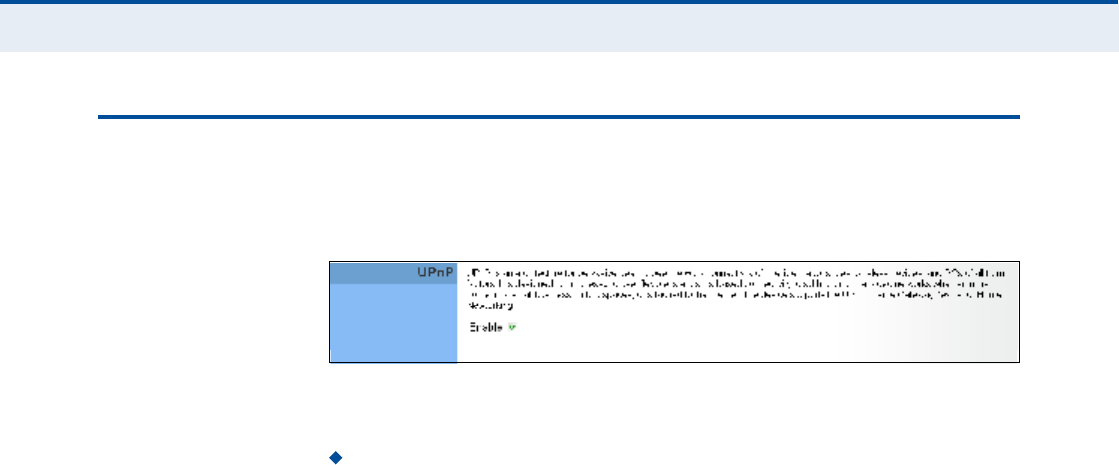
ËÐÒÐ
UPnP (Universal Plug and Play Forum) provides inter-connectivity between
devices supported by the same standard.
Figure 44: UPnP Setting
The following parameters are displayed in this section on this page:
UPnP Enables UpnP support on the unit.

64
ïï ÊÑ×Ð ÍÛÌÌ×ÒÙÍ
Voice over Internet Protocol (VoIP) technology is a way of using the
Internet to make phone calls. Phone calls can be tranmitted over the
Internet by encoding a voice call into data packets at one end and then
decoding it back into voice calls at the other end. This encoding and
decoding is from a analog signal (your voice) into a digital signal (data
packets) and then back into an analog signal.
The RG300 uses Session Initiation Protocol (SIP) as the control
mechanism that sets up, initiates, and terminates calls between a caller
and a called party. The SIP messaging makes use of "Proxy,# "Redirect,#
and "Registration# servers to process call requests and find the location of
called parties across the Internet. When SIP has set up a call between two
parties, the actual voice communication is a direct peer-to-peer connection
using the standard Real-Time Protocol (RTP), which streams the encoded
voice data across the network.
You can make VoIP calls by connecting a regular phone to one of the
RG300!s RJ-11 Phone ports. The RG300 allows up to two RJ-11 Phone ports
to be configured separately with different settings.
The VoIP configuration pages include the following options:
"SIP Account# on page65
"SIP Settings# on page66
"Speed Dial# on page67
"Dial Plan# on page68
"Call Feature# on page70
"Phone Settings# on page72
"Codecs# on page73
Ý
ØßÐÌÛÎ
ïï
| VoIP Settings
SIP Account
65
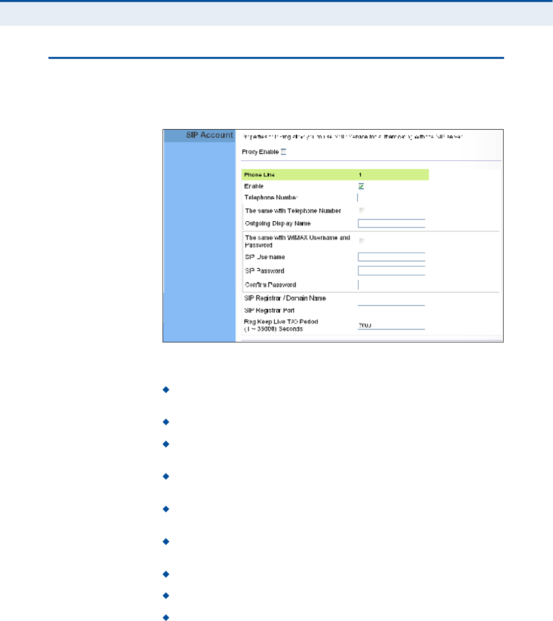
Í×Ð ßÝÝÑËÒÌ
From the VoIP SIP Account page, you can view the SIP account numbers
that have been provided by the service operator.
Figure 45: SIP Account Settings
The following parameters are displayed on this page:
Proxy Enable ! When enabled, forwards SIP messages to a SIP proxy
instead of a SIP domain.
Enable ! Enables the VoIP ports on the Gateway.
Telephone Number ! The phone number that is assigned to this
phone line.
The same with Telephone Number ! Uses the specified Telephone
Number as the Outgoing Display Name.
Outgoing Display Name ! The name that is displayed to the other
party during a call.
The same with WiMAX Username and Password ! Uses the
WiMAX user name and password as the SIP user name and password.
SIP Username ! Enter your SIP user name.
SIP Password ! Enter your SIP password.
Confirm Password ! Re-enter your SIP password.
Ý
ØßÐÌÛÎ
ïï
| VoIP Settings
SIP Settings
66
SIP Registrar/Domain Name $ Enter the IP address or server
domain name of the SIP server.
SIP Registrar Port ! Enter the port associated with SIP server traffic.
SIP Proxy Address/Domain Name ! Address of the VoIP service
provider SIP proxy server.
SIP Proxy Port ! The TCP port number used by the VoIP service
provider!s SIP proxy server.
Reg Keep Alive I/O Period $ The maximum time (in seconds)
between keep-alive messages sent to the SIP register server.
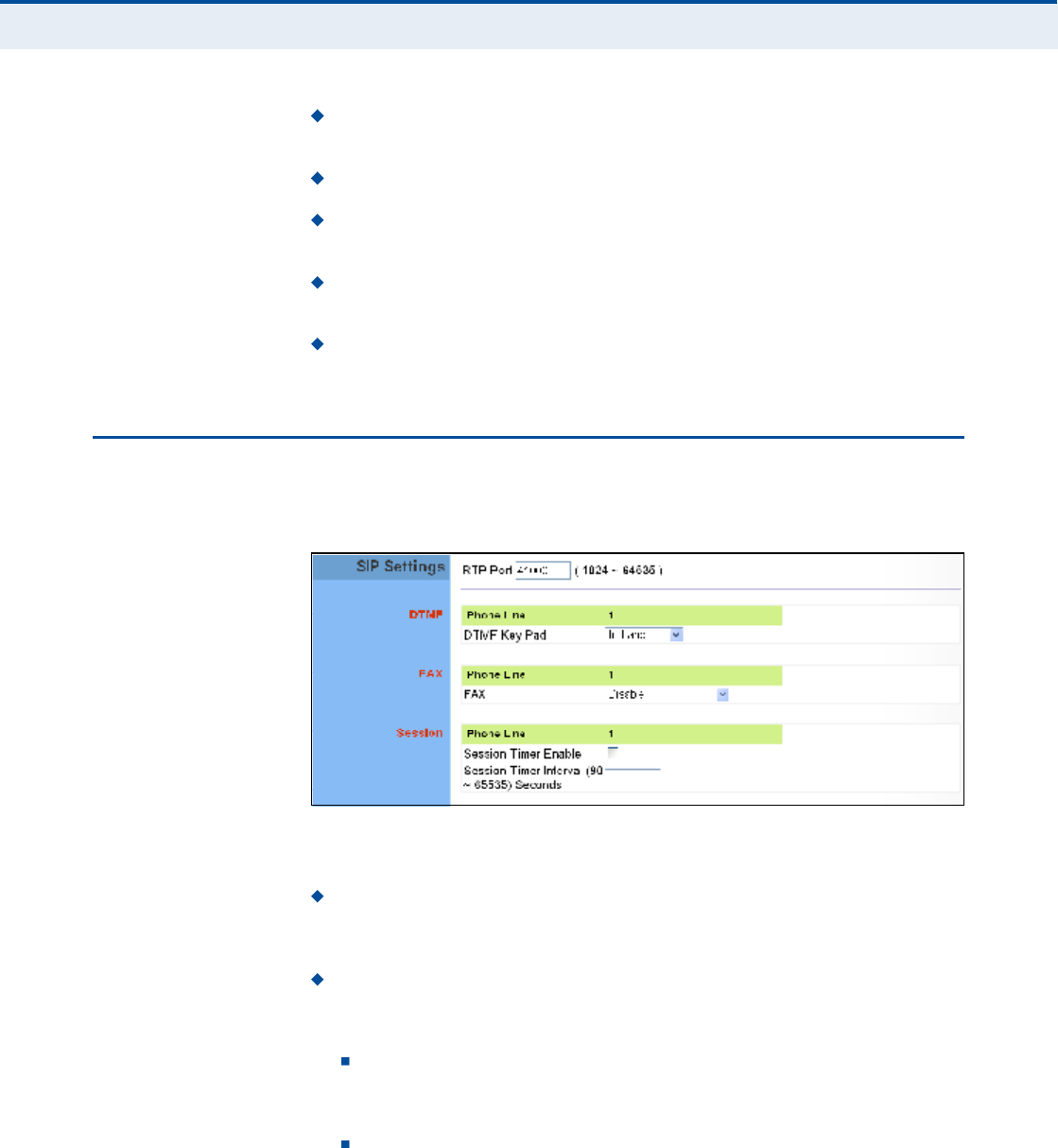
Í×Ð ÍÛÌÌ×ÒÙÍ
The SIP Setting page allows you to configure RTP, DTMF, and FAX settings.
Figure 46: SIP Settings
The following items are displayed on this page:
RTP Port ! The Real-time Transport Protocol (RTP) and Real-time
Control Protocol (RTCP) do not use specified port numbers. You can
specify a port base that the RTP and RTCP traffic can use.
DTMF Key Pad ! Enables the sending of dual-tone multi-frequency
(touch tone) phone signals over the VoIP connection. There are two
methods to choose from:
In-band ! The DTMF signals are sent over the RTP voice stream.
In the case when low-bandwidth codecs are used, the DTMF signals
may be distorted.
RFC2833 ! Uses the RFC 2833 method to relay the DTMF signals
over the RTP voice stream without any distortion.
Ý
ØßÐÌÛÎ
ïï
| VoIP Settings
Speed Dial
67
FAX ! Selects the method to use when sending fax messages over the
VoIP network from a fax machine connected to one of the RJ-11 Phone
ports on the Gateway.
FAX T.38 ! The SIP protocol sets up the VoIP call, then the T.38
Fax Relay protocol sends the fax data over the network.
FAX Pass-Through ! Enables voice calls and faxes to be sent
from the Phone port connection. For this option, fax signals are sent
over the VoIP network using the voice codec, just as if it were a
voice call.
Session Timer Enable ! Enables a limit on the duration of VoIP calls.
Session Timer Interval $ Sets the maximum time limit for VoIP calls.
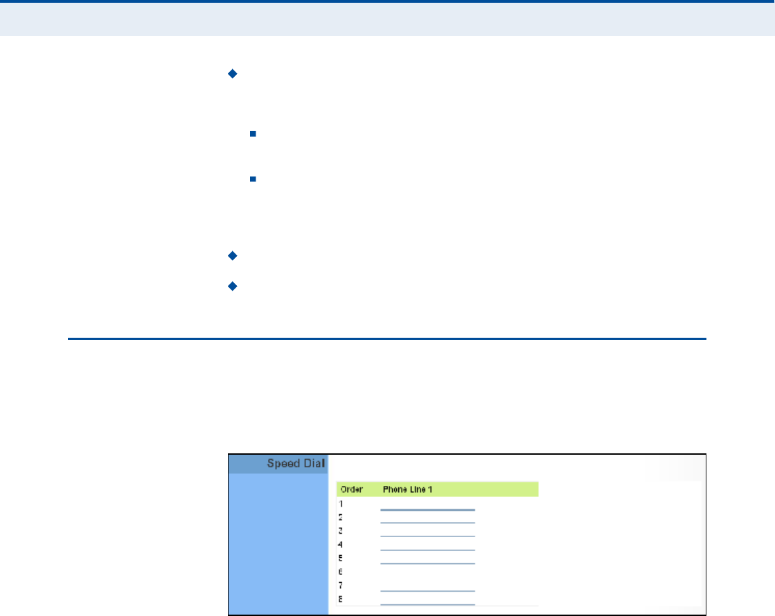
ÍÐÛÛÜ Ü×ßÔ
The Speed Dial page allows you to configure up to eight VoIP numbers that
are immediately dialed when a user enters the Speed Dial Key sequence
(as defined on the Dial Plan page) followed by a speed dial number.
Figure 47: Speed Dial
Ý
ØßÐÌÛÎ
ïï
| VoIP Settings
Dial Plan
68
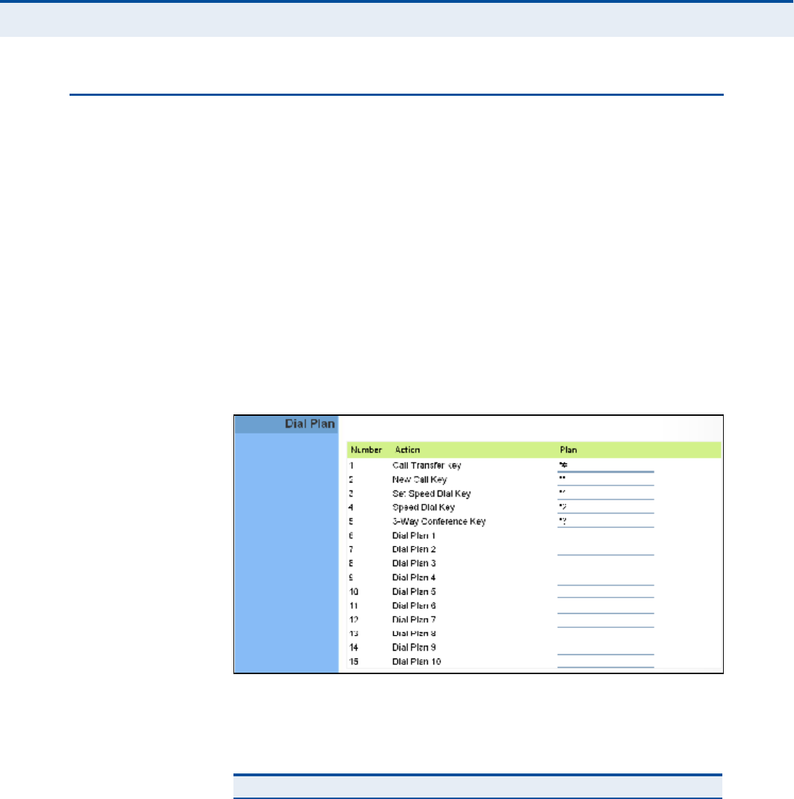
Ü×ßÔ ÐÔßÒ
Dial-plan strings specify key sequences used for specific calling features
(Transfer, New Call, 3-way conference), as well as defining call restriction
filters.
A dial plan can filter the number and pattern of digits that a user dials to
reach a particular telephone number. Access codes, area codes, specialized
codes, and combinations of the number of digits dialed can all be part of a
dial plan. This enables a user to predefine dialling sequences that are
permitted.
The dial-plan string consists of a single digit rule. A typical example of a
dial-plan string is: [0123]xxxxxx.t
Five standard dial plans are defined; Call Transfer Key, New Call Key, Set
Speed Dial Key, Speed Dial Key, and 3-way Conference. Up to 10 other dial
plans can be defined by the user.
Figure 48: Dial Plan Settings
The function of elements allowed in a dial plan are described in the table
below:
Table 5: Dial Plan Elements
Element Example Description
xxxxxRepresents a digit of any value ( 0 to 9) that can be dialed on a
phone. This example has a rule with four digits of any number.
.xx. Indicates zero or more occurrences of the previous symbol. The
example acts like a wildcard, meaning any dialed phone number
of two or more digits is allowed.
0-901xxIndicates dialed digits that must be matched. This example only
allows four-digit numbers starting "01.#

Ý
ØßÐÌÛÎ
ïï
| VoIP Settings
Dial Plan
69
When a user dials a series of digits, the dial-plan rule is tested for a
possible match. If a match is made, the dialed sequence is transmitted. If
no match is made, the dialed number is blocked and the user will hear an
error tone.
A dial-plan string cannot include spaces between elements. Dialed
sequences that are longer than specified in a dial-plan rule are truncated
after the number of specified digits. For example, if the dial-plan rule is
"011x# and "0115678# is dialed, only the digit sequence "0115# is
transmitted.
[ ][125-8] Limits a dialed digit to specified values or a range of values. The
example specifies that only digits 1, 2, 5, 6, 7, and 8 are
permitted.
txx.tThe timeout indicator that can placed after dialed digits or at the
end of the dial-plan string.
Table 5: Dial Plan Elements
Element Example Description

Ý
ØßÐÌÛÎ
ïï
| VoIP Settings
Call Feature
70
ÝßÔÔ ÚÛßÌËÎÛ
The RG300 allows you to configure several call features, such as call
waiting and call-forwarding. Other call features can be implemented by
pressing specific phone buttons or entering dial patterns.
Ò
ÑÌÛ
æ
Some call features may be dependent on support at the SIP server.
Check with the SIP service provider.
Figure 49: Call Features
The following items are displayed on this page:
Call Waiting $ Enables a call waiting alert. If during a call there is
another incoming call, an alert tone is heard. You can place the active
call on hold (press the "Flash# or "Flash Hook# button on the phone)
and switch to the incoming call.
Call Transfer ! Transfers any received call to another number you
specify.
Blind Transfer $ During a call press the "Flash# button, which
puts the caller on hold, then enter the transfer key sequence (as
defined on the Dial Plan page; default "*##). You can then dial the
transfer number. The call is transfered immediately and you can
hang up. The transfered call shows the caller ID of the original
calling party and not your caller ID.
Early Transfer $ During a call press the "Flash# button, which puts
the caller on hold, then enter the new call key sequence (as defined
on the Dial Plan page; default "**#). You can then dial the transfer
number. When you hear the transfer number ringtone, enter the
transfer key sequence (as defined on the Dial Plan page; default
"*##) and then hang up. The transfered call initially shows your

Ý
ØßÐÌÛÎ
ïï
| VoIP Settings
Call Feature
71
caller ID when the transferee phone is ringing, but then shows the
original calling party ID as soon as you hang up.
Attended Transfer $ During a call press the "Flash# button, which
puts the caller on hold, then enter the new call key sequence (as
defined on the Dial Plan page; default "**#). You can then dial the
transfer number and talk to the transferee. After speaking to the
transferee, enter the transfer key sequence (as defined on the Dial
Plan page; default "*##) and then hang up to transfer the call. The
transfered call shows your caller ID and not the caller ID of the
original calling party.
Call Forward ! Configures settings that control various call
forwarding features.
Always Forward Number $ Forwards an incoming call to another
number.
On Busy Forward Number $ When Call Waiting is disabled,
specifies another phone number to which incoming calls are
forwarded when the phone is busy.
No Answer Forward Number $ Another phone number to which
incoming calls are forwarded when there is no answer.
No Answer Forward Timer $ The time a call waits for an answer
before being forwarded to the No Answer Forward Phone Number.
(Must be less than or equal to the value of Answer Timeout; Range:
0~20 seconds)
Ý
ØßÐÌÛÎ
ïï
| VoIP Settings
Phone Settings
72
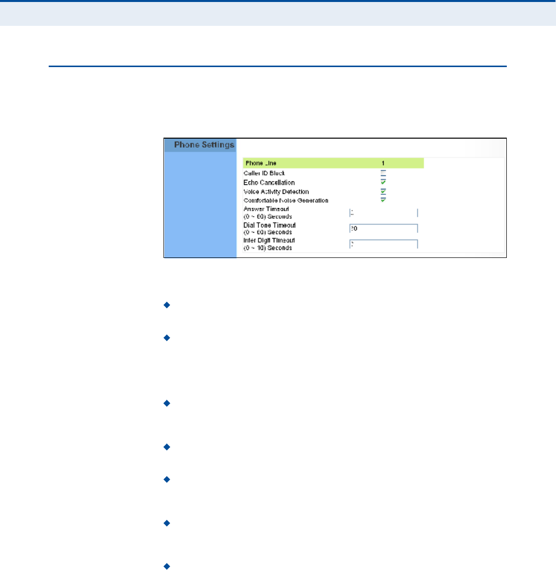
ÐØÑÒÛ ÍÛÌÌ×ÒÙÍ
The Phone Settings page allows you to configure control features that
affect a phone connected to a VoIP port.
Figure 50: Phone Settings
The following items are displayed on this page:
Caller ID Block ! Check this box to enable a block on the displayed
ID of incoming calls.
Echo Cancellation $ Enables a time delay for voice echo cancellation.
A voice echo can be created on some two-wire phone loops, which
becomes increasingly louder and annoying when there is a long delay.
If voice echo is a problem during a call, you can enable this parameter
to try and reduce or remove it.
Voice Activation Detection $ Enables the detection of periods of
silence in the audio stream so that they are not transmitted over the
network.
Comfortable Noise Generation $ Creates artificial noise for the
listener during detected silent intervals in the audio stream.
Answer Timeout $ The time after which a no answer message is sent
to the caller. (Range: 0-60 seconds; Setting of zero disables the
timeout)
Dial Tone Timeout $ The length of time a dial tone is heard on a
connected phone. (Range: 0-60 seconds; Setting of zero disables the
timeout)
Inter Digit Timeout $ The maximum time delay allowed between
each dialed digit. When the time is exceeded, a call is made using the
dialed digits. (Range:0-10seconds; Setting of zero disables the
timeout)

Ý
ØßÐÌÛÎ
ïï
| VoIP Settings
Codecs
73
ÝÑÜÛÝÍ
A codec (coder/decoder) is the way a voice analog signal is converted into
a digital bitstream to send over the network, and how it is converted back
into an analog signal at the receiving end. Codecs differ in the type of data
compression that is used to save network bandwidth and in the time delay
caused in the signal. This results in different voice quality experienced by
the user.
The voice codecs in common use today have been standardized by the
International Telecommunication Union Telecommunication Standardization
Sector (ITU-T) and are identified by a standard number, such as G.711.
The same codec must be supported at each end of a VoIP call to be able to
encode and decode the signal. Since devices in other networks may want
to use different codecs, the RG300 supports several common standards.
Figure 51: VoIP Codecs
The following items are displayed on this page:
Codecs $ Lists the codecs supported by the Gateway. You can enable
specific codecs to use, or enable all. Alternatively, you may want to
disable certain codecs, such as high-bandwidth codecs, to preserve
network bandwidth.
PCMA (G.711 ALaw) $ The ITU-T G.711 with A-law standard
codec that uses Pulse Code Modulation (PCM) to produce a 64 Kbps
high-quality voice data stream. This standard is used in Europe and
most other countries around the world.
PCMU (G.711 ULaw) $ The ITU-T G.711 with mu-law standard
codec that uses Pulse Code Modulation (PCM) to produce a 64 Kbps
high-quality voice data stream. This standard is used in North
America and Japan.
G.729a $ The ITU-T G.729ab standard codec that uses Conjugate
Structure Algebraic-Code Excited Linear Prediction (CS-ACELP) with
silence suppression to produce a low-bandwidth data stream of 8
Kbps. Note that DTMF and fax tones do not transport reliably with
this codec, it is better to use G.711 for these signals.
Priority List $ The Gateway automatically negotiates the codec to use
for each called party. You can specify a priority for the codecs that you
prefer to use. Select a codec in the list, then use the UP and DOWN

Ý
ØßÐÌÛÎ
ïï
| VoIP Settings
Codecs
74
buttons to set the priority. The Gateway attempts to use the codec
highest in the list before trying the next lower one.

75
ïî É×óÚ× ÍÛÌÌ×ÒÙÍ
The RG300 includes an IEEE 802.11n radio interface for local Wi-Fi
communications. The Wi-Fi set up pages include configuration options for
the radio signal characteristics and Wi-Fi security.
The Wi-Fi configuration pages include the following options:
"Basic Wireless Settings# on page76
"Advanced Wireless Settings# on page78
"Wireless Security# on page79
"ACL Settings# on page83

Ý
ØßÐÌÛÎ
ïî
| Wi-Fi Settings
Basic Wireless Settings
76
ÞßÍ×Ý É×ÎÛÔÛÍÍ ÍÛÌÌ×ÒÙÍ
From the WiFi menu, click on Basic to configure basic settings for the unit!s
Wi-Fi radio interface. The unit!s radio can operate in six modes,
IEEE802.11b/g mixed, 802.11b only, 802.11g only, 802.11n only,
802.11g/n mixed, and 802.11b/g/n mixed.
Note that IEEE 802.11g is backward compatible with 802.11b, and 802.11n
is backward compatible with 802.11b/g at slower data transmit rates.
Figure 52: Wireless Settings
The following items are displayed on this page:
Radio Enable $ Enables or disables the radio.
Network Mode $ Defines the radio operating mode.
11b/g mixed: Both 802.11b and 802.11g clients can communicate
with the Wi-Fi radio (up to 108 Mbps), but data transmission rates
may be slowed to compensate for 802.11b clients. Any 802.11n
clients will also be able to communicate with the Wi-Fi radio, but
they will be limited to 802.11g protocols and data transmission
rates.
11b only: All 802.11b, 802.11g, and 802.11n clients will be able to
communicate with the Wi-Fi radio, but the 802.11g and 802.11n
clients will be limited to 802.11b protocols and data transmission
rates (up to 11 Mbps).
11g only: Both 802.11g and 802.11n clients will be able to
communicate with the Wi-Fi radio, but the 802.11n clients will be
limited to 802.11g protocols and data transmission rates (up to
54Mbps). Any 802.11b clients will not be able to communicate with
the Wi-Fi radio.
11n only: Only 802.11n clients will be able to communicate with
the Wi-Fi radio (up to 150 Mbps).
11g/n mixed: Both 802.11g and 802.11n clients can communicate
with the Wi-Fi radio (up to 150 Mbps), but data transmission rates
may be slowed to compensate for 802.11g clients.

Ý
ØßÐÌÛÎ
ïî
| Wi-Fi Settings
Basic Wireless Settings
77
11b/g/n Mixed: All 802.11b/g/n clients can communicate with the
Wi-Fi radio (up to 150 Mbps), but data transmission rates may be
slowed to compensate for 802.11b/g clients.
SSID $ The name of the wireless network service provided by the Wi-
Fi radio. Clients that want to connect to the network must set their
SSID to the same as that of the Wi-Fi radio. Select "CUSTOMIZED# to
set a specific text string, or select "MAC# to use the device MAC address
as the SSID. (Range: 1-32 characters)
Hidden $ By default, the Wi-Fi radio always broadcasts the SSID in its
beacon signal. Disabling the SSID broadcast increases security of the
network because wireless clients need to already know the SSID before
attempting to connect.
Country Code $ The country code restricts operation of the Wi-Fi
radio to the channels and transmit power levels permitted for Wi-Fi
networks in the specified region. You must set the correct Country Code
to be sure the radio conforms to local regulations. (Options: United
States, Japan, France, Taiwan, Ireland)
Ý
ßËÌ×ÑÒ
æ
You must set the country code to the country of operation.
Setting the country code restricts operation of the access point to the radio
channels and transmit power levels permitted for wireless networks in the
specified country.
Channel $ The radio channel that the Wi-Fi radio uses to communicate
with wireless clients. When multiple access points are deployed in the
same area, set the channel on neighboring access points at least five
channels apart to avoid interference with each other. For example, you
can deploy up to three access points in the same area using channels 1,
6, 11. Note that wireless clients automatically set the channel to the
same as that used by the Wi-Fi radio to which it is linked. Selecting
Auto Select enables the Wi-Fi radio to automatically select an
unoccupied radio channel.
Ò
ÑÌÛ
æ
If you experience poor performance, you may be encountering
interference from another wireless device. Try changing the channel, as
this may eliminate interference and increase performance. Channels 1, 6,
and 11, as the three non-overlapping channels in the 2.4 GHz band, are
preferred.

Ý
ØßÐÌÛÎ
ïî
| Wi-Fi Settings
Advanced Wireless Settings
78
ßÜÊßÒÝÛÜ É×ÎÛÔÛÍÍ ÍÛÌÌ×ÒÙÍ
The Advanced Settings page includes additional parameters concerning the
wireless network and Wi-Fi Multimedia settings.
Figure 53: Advanced Wireless Settings
The following items are displayed on this page:
Beacon Period $ The rate at which beacon signals are transmitted
from the access point. The beacon signals allow wireless clients to
maintain contact with the access point. They may also carry power-
management information. (Range: 20-999 TUs)
DTIM Period $ The rate at which stations in sleep mode must wake
up to receive broadcast/multicast transmissions.
Known also as the Delivery Traffic Indication Map (DTIM) interval, it
indicates how often the MAC layer forwards broadcast/multicast traffic,
which is necessary to wake up stations that are using Power Save
mode. The value of one beacon indicates that the access point will save
all broadcast/multicast frames for the Basic Service Set (BSS) and
forward them after every beacon. Using smaller DTIM intervals delivers
broadcast/multicast frames in a more timely manner, causing stations
in Power Save mode to wake up more often and drain power faster.
Using higher DTIM values reduces the power used by stations in Power
Save mode, but delays the transmission of broadcast/multicast frames.
(Range: 1-255 beacons)
Frag Threshold Configures the minimum packet size that can be
fragmented when passing through the access point. Fragmentation of
the PDUs (Package Data Unit) can increase the reliability of
transmissions because it increases the probability of a successful
transmission due to smaller frame size. If there is significant
interference present, or collisions due to high network utilization, try
setting the fragment size to send smaller fragments. This will speed up
the retransmission of smaller frames. However, it is more efficient to
set the fragment size larger if very little or no interference is present
because it requires overhead to send multiple frames. (Range:256-
2346bytes)
RTS Threshold $ Sets the packet size threshold at which a Request to
Send (RTS) signal must be sent to a receiving station prior to the
sending station starting communications. The access point sends RTS

Ý
ØßÐÌÛÎ
ïî
| Wi-Fi Settings
Wireless Security
79
frames to a receiving station to negotiate the sending of a data frame.
After receiving an RTS frame, the station sends a CTS (clear to send)
frame to notify the sending station that it can start sending data.
If the RTS threshold is set to 0, the access point always sends RTS
signals. If set to 2347, the access point never sends RTS signals. If set
to any other value, and the packet size equals or exceeds the RTS
threshold, the RTS/CTS (Request to Send / Clear to Send) mechanism
will be enabled.
The access points contending for the medium may not be aware of each
other. The RTS/CTS mechanism can solve this "Hidden Node Problem.#
(Range: 1-2347 bytes)
TX Power Adjusts the power of the radio signals transmitted from
the unit. The higher the transmission power, the farther the
transmission range. Power selection is not just a trade off between
coverage area and maximum supported clients. You also have to
ensure that high-power signals do not interfere with the operation of
other radio devices in the service area. (Range: 1 - 100)
Short Slot $ Sets the basic unit of time the access point uses for
calculating waiting times before data is transmitted. A short slot time
(9microseconds) can increase data throughput on the access point, but
requires that all clients can support a short slot time (that is, 802.11g-
compliant clients must support a short slot time). A long slot time
(20microseconds) is required if the access point has to support
802.11b clients.
É×ÎÛÔÛÍÍ ÍÛÝËÎ×ÌÇ
The RG300!s Wi-Fi interface is configured by default as an "open system,#
which broadcasts a beacon signal including the configured SSID. Wireless
clients with a configured SSID of "ANY# can read the SSID from the
beacon, and automatically set their SSID to allow immediate connection to
the wireless network.
To implement wireless network security, you have to employ two main
functions:
Authentication It must be verified that clients attempting to connect
to the network are authorized users.
Traffic Encryption Data passing between the unit and clients must be
protected from interception and evesdropping.
The RG300!s Wi-Fi interface supports supports five different security
mechanisms that provide various levels of authentication and encryption
depending on the requirements of the network.
Click on "Wi-Fi,# followed by "Security#.

Ý
ØßÐÌÛÎ
ïî
| Wi-Fi Settings
Wireless Security
80
Figure 54: Security Mode Options
The supported security mechanisms and their configuration parameters are
described in the following sections:
OPEN, SHARED $ See "Wired Equivalent Privacy (WEP)# on page80.
WPAPSK, WPA2PSK, WPAPSK/WPA2PSK mixed mode $ See
"WPA Pre-Shared Key# on page81.
É×ÎÛÜ ÛÏË×ÊßÔÛÒÌ
ÐÎ×ÊßÝÇ øÉÛÐ÷
WEP provides a basic level of security, preventing unauthorized access to
the network, and encrypting data transmitted between wireless clients and
an access point. WEP uses static shared keys (fixed-length hexadecimal or
alphanumeric strings) that are manually distributed to all clients that want
to use the network.
When you select to use WEP, be sure to define at least one static WEP key
for user authentication or data encryption. Also, be sure that the WEP
shared keys are the same for each client in the wireless network.
Figure 55: Security Mode - WEP
The following items are displayed in this section on this page:
Auth Mode $ Configures the WEP security mode used by clients.
When using WEP, be sure to define at least one static WEP key for the
RG300 and all its clients.
OPEN $ Open-system authentication accepts any client attempting
to connect the RG300 without verifying its identity. In this mode the
default data encryption type is "WEP.#
SHARED $ The shared-key security uses a WEP key to
authenticate clients connecting to the network and for data
encryption.
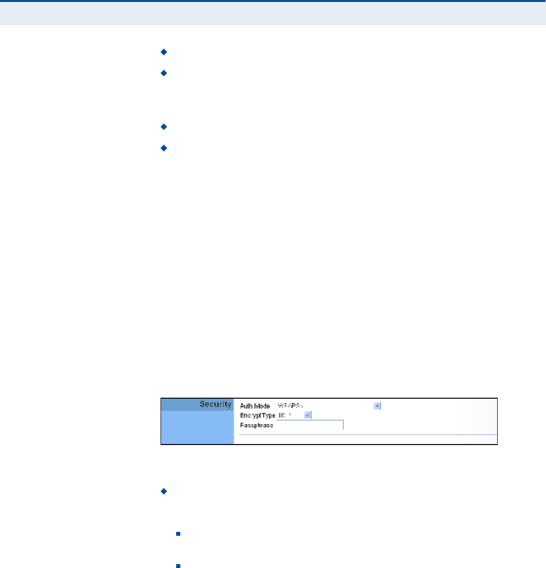
Ý
ØßÐÌÛÎ
ïî
| Wi-Fi Settings
Wireless Security
81
Encrypt Type $ Selects WEP for data encryption (OPEN mode only).
Default ID $ Selects the WEP key number to use for authentication or
data encryption. If wireless clients have all four WEP keys configured to
the same values, you can change the encryption key to any of the
settings without having to update the client keys. (Range:1~4)
Key 1~4 Type $ Sets WEP key type as ASCII or hexadecimal.
Key 1~4 String $ Sets WEP key values. The user must first select
ASCII or hexadecimal keys. Each WEP key has an index number. Enter
key values that match the key type and length settings. Enter 5
alphanumeric characters or 10 hexadecimal digits for 64-bit keys, or
enter 13 alphanumeric characters or 26 hexadecimal digits for 128-bit
keys.
ÉÐß ÐÎÛóÍØßÎÛÜ
ÕÛÇ
Wi-Fi Protected Access (WPA) was introduced as an interim solution for the
vulnerability of WEP pending the adoption of a more robust wireless
security standard. WPA2 includes the complete wireless security standard,
but also offers backward compatibility with WPA. Both WPA and WPA2
provide an "enterprise# and "personal# mode of operation.
For small home or office networks, WPA and WPA2 provide a simple
"personal# operating mode that uses just a pre-shared key for network
access. The WPA Pre-Shared Key (WPA-PSK) mode uses a common
password phrase for user authentication that is manually entered on the
access point and all wireless clients. Data encryption keys are
automatically generated by the access point and distributed to all clients
connected to the network.
Figure 56: Security Mode - WPA-PSK
The following items are displayed in this section on this page:
Auth Mode $ Configures the WPA-PSK and WPA2-PSK security modes
used by clients. When using WPA-PSK or WPA2-PSK, be sure to define
the shared key for the RG300 and all its clients.
WPAPSK $ Clients using WPA with a Pre-shared Key are accepted
for authentication. The default data encryption type for WPA is TKIP.
WPA2PSK $ Clients using WPA2 with a Pre-shared Key are
accepted for authentication. The default data encryption type for
WPA is AES.

Ý
ØßÐÌÛÎ
ïî
| Wi-Fi Settings
Wireless Security
82
WPAPSK/WPA2PSK mixed mode $ Clients using WPA or WPA2
with a Pre-shared Key are accepted for authentication. The default
data encryption type is TKIP/AES.
EncryptType $ Selects the data encryption type to use. (Default is
determined by the Security Mode selected.)
TKIP $ Uses Temporal Key Integrity Protocol (TKIP) keys for
encryption. WPA specifies TKIP as the data encryption method to
replace WEP. TKIP avoids the problems of WEP static keys by
dynamically changing data encryption keys.
AES $ Uses Advanced Encryption Standard (AES) keys for
encryption. WPA2 uses AES Counter-Mode encryption with Cipher
Block Chaining Message Authentication Code (CBC-MAC) for
message integrity. The AES Counter-Mode/CBCMAC Protocol (AES-
CCMP) provides extremely robust data confidentiality using a 128-
bit key. Use of AES-CCMP encryption is specified as a standard
requirement for WPA2. Before implementing WPA2 in the network,
be sure client devices are upgraded to WPA2-compliant hardware.
TKIPAES $ Uses either TKIP or AES keys for encryption. WPA and
WPA2 mixed modes allow both WPA and WPA2 clients to associate
to a common SSID. In mixed mode, the unicast encryption type
(TKIP or AES) is negotiated for each client.
Pass Phrase $ The WPA Preshared Key can be input as an ASCII
string (an easy-to-remember form of letters and numbers that can
include spaces) or Hexadecimal format. (Range: 8~63 ASCII
characters, or exactly 64 Hexadecimal digits)
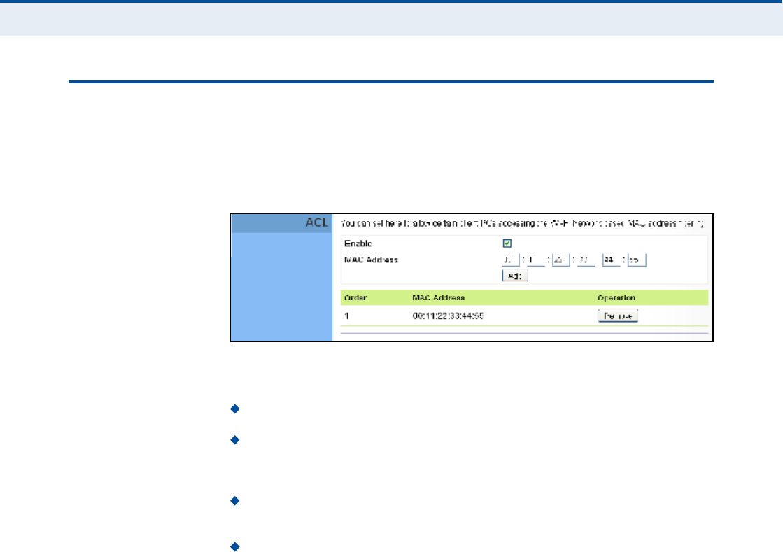
Ý
ØßÐÌÛÎ
ïî
| Wi-Fi Settings
ACL Settings
83
ßÝÔ ÍÛÌÌ×ÒÙÍ
Wireless clients can be authenticated for network access by checking their
MAC address against a local database configured on the RG300. You can
configure a list of up to 32 wireless client MAC addresses in the filter list to
allow network access.
Figure 57: ACL Settings
The following items are displayed on this page:
Enable $ Enables the ACL feature.
MAC Address $ Physical address of a client. Enter six pairs of
hexadecimal digits separated by colons; for example,
00:90:D1:12:AB:89.
Add $ Click to list a new specified MAC address in the MAC
Authentication Table.
Operation $ Click the Remove button to delete the specified MAC
address from the table.

84
ïí ÏÑÍ ÝÑÒÚ×ÙËÎßÌ×ÑÒ
The RG300 supports Quality of Service (QoS) settings that enable traffic
rate limits to be set for all or specific LAN clients.
The QoS configuration pages include the following options:
"QoS Settings# on page85
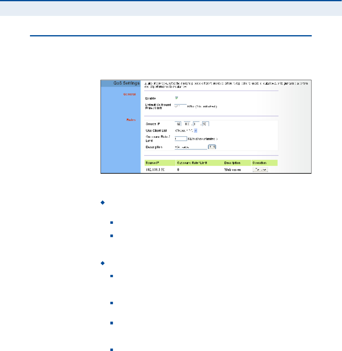
Ý
ØßÐÌÛÎ
ïí
| QoS Configuration
QoS Settings
85
ÏÑÍ ÍÛÌÌ×ÒÙÍ
From the QoS Settings page, you can set rate limits for outbound (WiMAX
uplink) traffic from all or specified clients.
Figure 58: QoS Settings
The following parameters are displayed on this page:
General $ Sets QoS parameters that apply to all LAN clients (except
those listed in the QoS Rules table):
Enable $ Enables the QoS settings on the Gateway.
Default Outbound Rate/Limit $ Sets a rate limit for the
outbound traffic from all clients not specified in the QoS Rules table.
The rate is specified in kilobytes per second (0 means unlimited).
Rules $ Specifies the QoS rate limits for specified client source IPs:
Source IP $ Specifies a source IP address on the local network.
The IP address can also be selected from the DHCP client list, as
indicated by "Use Client List.#
Use Client List Enables the Source IP to be selected from the
DHCP client list.
Outbound Rate/Limit $ Sets a rate limit for the outbound traffic
from the specified source IP in kilobytes per second (0 means
unlimited).
Description $ A text srting that identifies the rule.

86
Í
ÛÝÌ×ÑÒ
×××
ßÐÐÛÒÜ×ÝÛÍ
This section provides additional information and includes these items:
"Troubleshooting# on page87
"Hardware Specifications# on page89
"Cables and Pinouts# on page93

87
ßÌÎÑËÞÔÛÍØÑÑÌ×ÒÙ
Ü×ßÙÒÑÍ×ÒÙ ÔÛÜ ×ÒÜ×ÝßÌÑÎÍ
ÝßÒÒÑÌ ÝÑÒÒÛÝÌ ÌÑ ÌØÛ ×ÒÌÛÎÒÛÌ
If you cannot access the Internet from the PC, check the following:
If you cannot access the Internet, be sure your Windows system is
correctly configured for TCP/IP. The IP settings should be set to "obtain
an IP address automatically.#
You may be out of the service area of the WiMAX network. Check with
the WiMAX service provider for service coverage information.
If you cannot resolve the problem, check the System Status page of the
web interface and contact your WiMAX service provider.
Table 6: Troubleshooting Chart
Symptom Action
Power LED is Off AC power adapter may be disconnected. Check
connections between the unit, the AC power adapter,
and the wall outlet.
Power LED is Red The unit has detected a system error. Reboot the unit to
try and clear the condition.
If the condition does not clear, contact your local dealer
for assistance.
WiMAX Signal LEDs are Off Move the location of the unit.
Check with the WiMAX service provider for service
coverage information.
LAN link LED is Off Verify that the unit and attached device are powered on.
Be sure the cable is plugged into both the unit and
corresponding device.
Verify that the proper cable type is used and its length
does not exceed specified limits.
Check the cable connections for possible defects.
Replace the defective cable if necessary.

ß
ÐÐÛÒÜ×È
ß
| Troubleshooting
Cannot Access Web Management
88
ÝßÒÒÑÌ ßÝÝÛÍÍ ÉÛÞ ÓßÒßÙÛÓÛÒÌ
If the management interface cannot be accessed using a web browser:
Be sure the management station is correctly configured for TCP/IP. The
IP settings should be set to "obtain an IP address automatically.#
Try a Ping command from the management station to the unit!s IP
address to verify that the entire network path between the two devices
is functioning correctly.
Check that the management station has a valid network connection and
that the Ethernet port that you are using has not been disabled.
Check the network cabling between the management station and the
unit. If the problem is not resolved, try using a different port or a
different cable.
ÚÑÎÙÑÌ ÑÎ ÔÑÍÌ ÌØÛ ÐßÍÍÉÑÎÜ
Set the unit to its default configuration by pressing the reset button on the
base for 5 seconds or more. Then use the default password to access the
management interface.
ÎÛÍÛÌÌ×ÒÙ ÌØÛ ËÒ×Ì
If all other recovery measures fail and the unit is still not functioning
properly, take either of these steps:
Reset the unit using the web interface, or through a power reset.
Reset the unit to its factory default configuration by pressing the reset
button on the base for 5 seconds or more. Then use the default
password to access the management interface.

89
ÞØßÎÜÉßÎÛ ÍÐÛÝ×Ú×ÝßÌ×ÑÒÍ
ÐØÇÍ×ÝßÔ ÍÐÛÝ×Ú×ÝßÌ×ÑÒÍ
ÐÑÎÌÍ 1~4 LAN ports, 10/100BASE-TX with auto-negotiation, RJ-45 connector
1~2 FXS ports, RJ-11 connector
ÒÛÌÉÑÎÕ ×ÒÌÛÎÚßÝÛ RJ-45 connector, auto MDI/X:
10BASE-T: RJ-45 (100-ohm, UTP cable; Category 3 or better)
100BASE-TX: RJ-45 (100-ohm, UTP cable; Category 5 or better)
ÔÛÜ ×ÒÜ×ÝßÌÑÎÍ System: Power, WiMAX signal strength, WiFi,
Ports: Link/Activity
ßÝ ÐÑÉÛÎ ßÜßÐÌÛÎ Input: 100-240 VAC, 50-60 Hz, 0.5 A maximum
Output: 12 VDC, 1 A
ËÒ×Ì ÐÑÉÛÎ ÍËÐÐÔÇ DC Input: 12 VDC, 1 A maximum
Power Consumption: 12 W maximum
ÐØÇÍ×ÝßÔ Í×ÆÛ 181.5 x 198.5 x 79 mm (7.15 x 7.81 x 3.11 in)
ÉÛ×ÙØÌ 412 g (14.5 oz)
ÌÛÓÐÛÎßÌËÎÛ Operating: -5 to 45 °C (23 to 113 °F)
Storage: -40 to 75 °C (-40 to 167 °F)
ØËÓ×Ü×ÌÇ 5% to 95% (non-condensing)

ß
ÐÐÛÒÜ×È
Þ
| Hardware Specifications
WiMAX Specifications
90
É×ÓßÈ ÍÐÛÝ×Ú×ÝßÌ×ÑÒÍ
ßÒÌÛÒÒßÍ Pattern: Omnidirectional
Transmit and Receive: One transmit and two receive with Maximal-Ratio
Combining (MRC). Support for transmitter diversity.
Gain: 6 dBi
Impedance: 50 Ohm
ÑÐÛÎßÌ×ÒÙ ÚÎÛÏËÛÒÝÇ FCC-2.5 GHz: 2496-2690 MHz
Taiwan NCC-2.5 GHz: 2500-2690 MHz
2.3 GHz: 2300-2390 MHz
Support for Full Scan and Partial Scan
ÝØßÒÒÛÔ ÞßÒÜÉ×ÜÌØ 2.5 GHz model: 5 and 10 MHz
ÓÑÜËÔßÌ×ÑÒ ÍÝØÛÓÛ Scaleable OFDMA employing Time-Division Duplex (TDD) mechanism
PRBS subcarrier randomization
Contains pilot, preamble, and ranging modulation
ÓÑÜËÔßÌ×ÑÒ ßÒÜ
ÝÑÜ×ÒÙ ÌÇÐÛÍ
Down Link: QPSK, 16 QAM, 64 QAM
Up Link: QPSK, 16 QAM
ÎÛÝÛ×ÊÛ ÍÛÒÍ×Ì×Ê×ÌÇ -94 dBm maximum
ÊÑ×Ð ÍÐÛÝ×Ú×ÝßÌ×ÑÒÍ
ÊÑ×ÝÛ Í×ÙÒßÔ×ÒÙ
ÐÎÑÌÑÝÑÔ
SIP v2 (RFC 3261)
ÊÑ×ÝÛ ÝÑÜÛÝ G.711 (a-law and u-law)
G.729a
ÊÑ×ÝÛ ÏËßÔ×ÌÇ VAD (Voice Activity Detection)
CNG (Comfortable Noise Generation)
Echo cancellation

ß
ÐÐÛÒÜ×È
Þ
| Hardware Specifications
Wi-Fi Specifications
91
Adaptive jitter buffer, up to 200 milliseconds
DTMF tone detection and generation
ÝßÔÔ ÚÛßÌËÎÛÍ Caller ID number and name
Caller ID Block
Call transfer
Call waiting/hold/retrieve
3-way conference call
Call blocking
T.38 fax relay
Dial plan
Speed dial
Call forwarding: No Answer/Busy/All
ÎÛÒ øÎ×ÒÙ ÛÏË×ÊßÔÛÒÌ
ÒËÓÞÛÎ÷
3 REN total in system
É×óÚ× ÍÐÛÝ×Ú×ÝßÌ×ÑÒÍ
ÓßÈ×ÓËÓ èðîòïïÞñÙñÒ
øîð ÓØÆ÷ ÝØßÒÒÛÔÍ
FCC/NCC: 1-11
ETSI: 1-13
France: 10-13
ÑÐÛÎßÌ×ÒÙ ÚÎÛÏËÛÒÝÇ 2.4 ~ 2.4835 GHz (FCC, ETSI)
ÓÑÜËÔßÌ×ÑÒ ÌÇÐÛ 802.11n: BPSK, QPSK, OFDM
802.11g: BPSK, QPSK, OFDM
802.11b: CCK, BPSK, QPSK
ÎÚ ÑËÌÐËÌ ÐÑÉÛÎ 802.11b: 13 dBm
802.11g: 12 dBm
802.11n: 9 dBm
ÎÚ ÎÛÝÛ×ÊÛ ÍÛÒÍ×Ì×Ê×ÌÇ 802.11b: -85 dBm @ 11 Mbps
802.11g: -65 dBm @ 54 Mbps
802.11n: -61 dBm @ 150 Mbps

ß
ÐÐÛÒÜ×È
Þ
| Hardware Specifications
Compliances
92
ÝÑÓÐÔ×ßÒÝÛÍ
ÛÓ×ÍÍ×ÑÒÍ FCC CFR 47 Part 15 Class B
EN 55022 Class B
ÛÓÓËÒ×ÌÇ EN 55024 Class B
EN 301 489-1/4/17
É×ÓßÈ ÎßÜ×Ñ Í×ÙÒßÔ
ÝÛÎÌ×Ú×ÝßÌ×ÑÒ
US: 2.5 GHz - FCC CFR 47 Part 27M
CE: 2.3 GHz - EN 302 326
2.5 GHz - EN 302 544
NCC: PLMN09
É×óÚ× ÎßÜ×Ñ Í×ÙÒßÔ
ÝÛÎÌ×Ú×ÝßÌ×ÑÒ
FCC CFR 47 Part 15 Subpart C
EN 300 328
NCC: LP0002
ÍßÚÛÌÇ IEC/UL 60950-1
CE: EN 60950-1 (LVD)
NCC: CNS14336
ErP EN 62301
ÍÌßÒÜßÎÜÍ IEEE 802.16e-2005 WAVE 1 and WAVE 2
IEEE 802.3-2005 10BASE-T and 100BASE-TX
IEEE 802.11b, 802.11g, and 802.11n
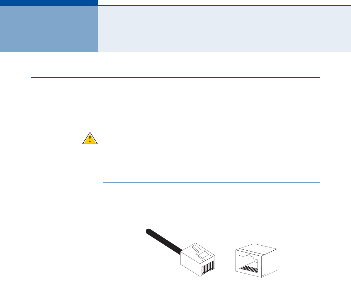
93
ÝÝßÞÔÛÍ ßÒÜ Ð×ÒÑËÌÍ
ÌÉ×ÍÌÛÜóÐß×Î ÝßÞÔÛ ßÍÍ×ÙÒÓÛÒÌÍ
For 10/100BASE-TX connections, a twisted-pair cable must have two pairs
of wires. Each wire pair is identified by two different colors. For example,
one wire might be green and the other, green with white stripes. Also, an
RJ-45 connector must be attached to both ends of the cable.
Ý
ßËÌ×ÑÒ
æ
Each wire pair must be attached to the RJ-45 connectors in a
specific orientation. (See "Straight-Through Wiring# on page94 and
"Crossover Wiring# on page95 for an explanation.)
Ý
ßËÌ×ÑÒ
æ
DO NOT plug a phone jack connector into the RJ-45 port. Use
only twisted-pair cables with RJ-45 connectors that conform with FCC
standards.
The following figure illustrates how the pins on the RJ-45 connector are
numbered. Be sure to hold the connectors in the same orientation when
attaching the wires to the pins.
Figure 59: RJ-45 Connector
ïðñïððÞßÍÛóÌÈ Ð×Ò
ßÍÍ×ÙÒÓÛÒÌÍ
Use unshielded twisted-pair (UTP) or shielded twisted-pair (STP) cable for
RJ-45 connections: 100-ohm Category 3 or better cable for 10 Mbps
connections, or 100-ohm Category 5 or better cable for 100 Mbps
connections. Also be sure that the length of any twisted-pair connection
does not exceed 100 meters (328 feet).
The RJ-45 ports on the unit supports automatic MDI/MDI-X operation, so
you can use straight-through or crossover cables for all network
connections to PCs, switches, or hubs. In straight-through cable, pins 1, 2,
3, and 6, at one end of the cable, are connected straight through to pins 1,
2, 3, and 6 at the other end of the cable.
ï
èèï
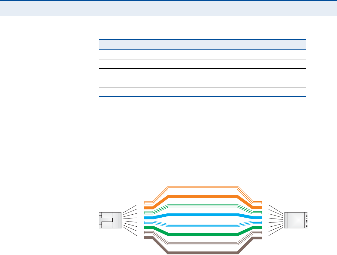
ß
ÐÐÛÒÜ×È
Ý
| Cables and Pinouts
Twisted-Pair Cable Assignments
94
ÍÌÎß×ÙØÌóÌØÎÑËÙØ
É×Î×ÒÙ
If the twisted-pair cable is to join two ports and only one of the ports has
an internal crossover (MDI-X), the two pairs of wires must be straight-
through.
Figure 60: Straight Through Wiring
Table 7: 10/100BASE-TX MDI and MDI-X Port Pinouts
PIN MDI Signal Namea
a.The "+# and "-# signs represent the polarity of the wires that make up each wire pair.
MDI-X Signal Name
1Transmit Data plus (TD+) Receive Data plus (RD+)
2Transmit Data minus (TD-) Receive Data minus (RD-)
3Receive Data plus (RD+) Transmit Data plus (TD+)
6Receive Data minus (RD-) Transmit Data minus (TD-)
4, 5, 7, 8 Not usedNot used
ɸ·¬»ñÑ®¿²¹»Í¬®·°»
Ñ®¿²¹»
ɸ·¬»ñÙ®»»²Í¬®·°»
Ù®»»²
ï
î
í
ì
ë
ê
é
è
ï
î
í
ì
ë
ê
é
è
Û×ßñÌ×ßëêèÞÎÖóìëÉ·®·²¹Í¬¿²¼¿®¼
ïðñïððÞßÍÛóÌÈͬ®¿·¹¸¬ó¬¸®±«¹¸Ý¿¾´»
Û²¼ß
Û²¼Þ
Þ´«»
ɸ·¬»ñÞ´«»Í¬®·°»
Þ®±©²
ɸ·¬»ñÞ®±©²Í¬®·°»

ß
ÐÐÛÒÜ×È
Ý
| Cables and Pinouts
Twisted-Pair Cable Assignments
95
ÝÎÑÍÍÑÊÛÎ É×Î×ÒÙ If the twisted-pair cable is to join two ports and either both ports are
labeled with an "X# (MDI-X) or neither port is labeled with an "X# (MDI), a
crossover must be implemented in the wiring.
Figure 61: Crossover Wiring
ɸ·¬»ñÑ®¿²¹»Í¬®·°»
Ñ®¿²¹»
ɸ·¬»ñÙ®»»²Í¬®·°»
ï
î
í
ì
ë
ê
é
è
ï
î
í
ì
ë
ê
é
è
Û×ßñÌ×ßëêèÞÎÖóìëÉ·®·²¹Í¬¿²¼¿®¼
ïðñïððÞßÍÛóÌÈÝ®±--±ª»®Ý¿¾´»
Û²¼ß
Û²¼Þ
Ù®»»²
Þ´«»
ɸ·¬»ñÞ´«»Í¬®·°»
Þ®±©²
ɸ·¬»ñÞ®±©²Í¬®·°»

ß
ÐÐÛÒÜ×È
Ý
| Cables and Pinouts
RJ-11 Port
96
ÎÖóïï ÐÑÎÌ
Standard telephone RJ-11 connectors and cabling can be found in several
common wiring patterns. These six-pin connectors can accommodate up to
three wire pairs (three telephone lines), but usually only one or two pairs
of conductor pins and wires are implemented.
The RJ-11 port on this device contains only one wire pair on the inner pins
(3 and 4).
Figure 62: RJ-11 Port Pinout
Table 8: RJ-11 Port Pinout
Pin Signal Name Wire Color
1Not used
2Not used
3Line 1 RingRed or Blue/White
4Line 1 TipGreen or White/Blue
5Not used
6Not used
ïîíìëê
λ¼±®
Þ´«»ñɸ·¬»
Ù
®»»²±®
ɸ·¬»
ñÞ´
«»
ÎÌ
Îãη²¹ÌãÌ·°

97
ÙÔÑÍÍßÎÇ
ïðÞßÍÛóÌ IEEE 802.3-2005 specification for 10 Mbps Ethernet over two pairs of
Category 3 or better UTP cable.
ïððÞßÍÛóÌÈ IEEE 802.3-2005 specification for 100 Mbps Fast Ethernet over two pairs of
Category 5 or better UTP cable.
ßÝÝÛÍÍ ÐÑ×ÒÌ An Wi-Fi internetworking device that seamlessly connects wired and
wireless networks.
ßËÌØÛÒÌ×ÝßÌ×ÑÒ The process to verify the identity of a client requesting network access.
ßËÌÑóÒÛÙÑÌ×ßÌ×ÑÒ Signalling method allowing each node to select its optimum operational
mode (speed and duplex mode) based on the capabilities of the node to
which it is connected.
ÞßÍÛ ÍÌßÌ×ÑÒ A WIMAX service provider!s equipment that is installed at a fixed location
to provide network connectivity for subscriber stations within a defined
service area.
ÞÛßÝÑÒ A signal periodically transmitted from a Wi-Fi access point that is used to
identify the network and maintain contact with wireless clients.
Ý×ÒÎ Carrier-to-Interference-Plus-Noise Ratio. A measurement of the channel
quality in a WiMAX link. Subscriber stations measure the received CINR
and send the information back to the base station. The base station can
then adjust modulation and coding for the link to optimize throughput.
ÝÛÒÌÛÎ ÚÎÛÏËÛÒÝÇ The radio frequency at the center of a WiMAX channel. WiMAX channels
can be of different widths (the channel bandwidth) and the transmitted
radio signal is spread across the full width of the channel.
ÝØßÒÒÛÔ ÞßÒÜÉ×ÜÌØ The range of frequencies occupied by a WiMAX radio signal. The amount of
information that can be transmitted in a radio signal is related to the
channel bandwidth, which is measured in Megahertz (MHz). WiMAX
supports a range of channel bandwidths that can be defined by the service

Ù
ÔÑÍÍßÎÇ
98
operator depending on performance requirements, operating preferences,
and regulatory constraints.
ÝÐÛ Customer-Premises Equipment. Terminal equipment provided by a service
provider that is located at a subscriber!s premises and supports a
communication channel between a customer and the service provider.
ÜÒÍ Domain Name System. A system used for translating host names for
network nodes into IP addresses.
ÜØÝÐ Dynamic Host Configuration Protocol. Provides a framework for passing
configuration information to hosts on a TCP/IP network. DHCP is based on
the Bootstrap Protocol (BOOTP), adding the capability of automatic
allocation of reusable network addresses and additional configuration
options.
ÛÒÝÎÇÐÌ×ÑÒ Data passing between a base station and subscribers uses encryption to
protect from interception and evesdropping.
ÛÌØÛÎÒÛÌ A popular local area data communications network, which accepts
transmission from computers and terminals.
ÛßÐ Extensible Authentication Protocol. An authentication protocol used to
authenticate subscribers. EAP is used with TLS or TTLS authentication to
provide "mutual authentication# between a subscriber and a WiMAX
network.
ØÌÌÐ Hypertext Transfer Protocol. HTTP is a standard used to transmit and
receive all data over the World Wide Web.
×ÝÓÐ Internet Control Message Protocol. A network layer protocol that reports
errors in processing IP packets. ICMP is also used by routers to feed back
information about better routing choices.
×ÛÛÛ èðîòïïÞThe Wi-Fi wireless standard that supports communications in the 2.4 GHz
band using Direct Sequence Spread Spectrum (DSSS). The standard
provides for data rates of 1, 2, 5.5, and 11 Mbps.
×ÛÛÛ èðîòïïÙThe Wi-Fi wireless standard that supports communications in the 2.4 GHz
band using using Orthogonal Frequency Division Multiplexing (OFDM). The
standard provides for data rates of 6, 9, 11, 12, 18, 24, 36, 48, 54 Mbps.
IEEE 802.11g is also backward compatible with IEEE 802.11b.

Ù
ÔÑÍÍßÎÇ
99
×ÛÛÛ èðîòïêÛThe WiMAX standard that provides mobile broadband wireless access using
Scalable Orthogonal Frequency Division Multiple Access (SOFDMA).
×Ð ßÜÜÎÛÍÍ The Internet Protocol (IP) address is a numerical identification assigned to
a device that communicates in a network using the Internet Protocol.
×ÍÐ Internet Service Provider. A company that offers an access service that
connects customers to the Internet.
ÔÛÜ Light emitting diode. Used for indicating a device or network condition.
ÔßÒ Local Area Network. A group of interconnected computer and support
devices.
ÓßÝ ßÜÜÎÛÍÍ The physical layer address used to uniquely identify network nodes.
ÓÍóÝØßÐÊî Microsoft!s version 2 of the Challenge-Handshake Authentication Protocol.
Introduced by Microsoft with Windows 2000, MS-CHAPV2 (defined in RFC
2759) provides mutual authentication between peers using user names
and passwords.
ÑÜÚÓ Orthogonal Frequency Division Multiplexing. The air interface defined for
IEEE 802.11g Wi-Fi. OFDM allows multiple users to transmit in an allocated
band by dividing the bandwidth into many narrow bandwidth carriers.
ÎÖóìë ÝÑÒÒÛÝÌÑÎ A connector for twisted-pair wiring.
ÎÍÍ× Receive Signal Strength Indicator. A measurement of the strength of a
received wireless signal. The higher the RSSI value, the stronger the
received signal from the antenna.
ÎÑßÓ×ÒÙ The process where a WiMAX subscriber can move onto another operator!s
network while maintaining a continuous connection.
ÍÑÚÜÓß Scalable Orthogonal Frequency Division Multiple Access. The air interface
defined for mobile WiMAX. SOFDMA is a multiple access method that allows
simultaneous transmissions to and from several users, employing a
subchannel structure that scales with bandwidth.
ÍÛÎÊ×ÝÛ ÐÎÑÊ×ÜÛÎ See Internet Service Provider.

Ù
ÔÑÍÍßÎÇ
100
ÍÍ×Ü Service Set Identifier. A name that is sent in packets over a Wi-Fi network,
which functions as a password for clients connecting to the network. The
SSID differentiates one Wi-Fi network from another.
ÍÒÌÐ Simple Network Time Protocol. SNTP allows a device to set its internal
clock based on periodic updates from a Network Time Protocol (NTP)
server. Updates can be requested from a specific NTP server, or can be
received via broadcasts sent by NTP servers.
Í×Ó Subscriber Identity Module. A standard for a small removable integrated
circuit card that securely stores information used to identify a mobile
wireless subscriber.
ÍËÞÍÝÎ×ÞÛÎ ÍÌßÌ×ÑÒ A general term for a customer!s WIMAX terminal equipment that provides
connectivity with a base station.
ÌÝÐñ×Ð Transmission Control Protocol/Internet Protocol. Protocol suite that
includes TCP as the primary transport protocol, and IP as the network layer
protocol.
ÌÔÍ Transport Layer Security. An standard defined in RFC 5216, EAP-TLS is an
authentication protocol that provides strong security through the use of
client-side certificates.
ÌÌÔÍ Tunneled Transport Layer Security. EAP-TTLS is a protocol extension of
EAP-TLS. The authentication server is authenticated to the client using its
Certification Authority certificate, this establishes a secure "tunnel#
through which the client is then authenticated.
ËÎÔ Uniform Resource Locator. An easy-to-read character string that is used to
represent a resource available on the Internet. For example, "http://
www.url-example.com/.#
ËÌÐ Unshielded twisted-pair cable.
ÉÛÐ Wired Equivalent Privacy. WEP is the Wi-Fi security based on the use of
RC4 encryption keys. Wi-Fi devices without a valid WEP key are excluded
from the network.
ÐÍÕ WPA Pre-shared Key. PSK security can be used for small Wi-Fi networks
that may not have the resources to configure and maintain a RADIUS

Ù
ÔÑÍÍßÎÇ
101
server. WPA provides a simple operating mode that uses just a pre-shared
password for network access.
É×ÓßÈ The IEEE 802.16 standard for Worldwide Interoperability for Microwave
Access. The IEEE 802.16-2004 standard, known as "fixed WiMAX,#
supports only point-to-point links and has no support for mobility. The IEEE
802.16e-2005 standard, known as "mobile WiMAX,# is an amendment to
IEEE 802.16-2004 and supports mobility. Note that mobile WiMAX standard
is not backward compatible with the fixed WiMAX standard.

102
×ÒÜÛÈ
ß
AC power adapter 18
administrator password, setting 32
administrator settings 32
Advanced Setup menu 27
AES encryption 82
authentication
type 79
authentication options 80
auto-logout time 33
Þ
beacon interval 78
button, Reset 18
Ý
cable assignments 93
cable connections 21
channel setting 77
channels, maximum 91
checklist 20
client filter, enable 54
Codec 73
configuration, basic 25
contents, package 20
Ü
data beacon rate 78
default Key, WEP 81
default settings, restore 34
defaults, factory 34
DHCP server 45
discard ping 53
downloading software 33
DTIM setting 78
dynamic DNS 43
dynamic IP, cable modem 39
Û
encryption 79
encryption options 80
Ethernet ports 17
Ú
factory defaults, restoring 34
firewall protection 53
firmware update 33
fixed-IP xDSL 39
fragmentation threshold 78
frequency setting 77
Ù
Gateway address 40, 60
gateway function 21
Ø
hacker attack, prevention 53
hardware, description 15
×
IEEE 802.11g 75
configuring interface 76
initial configuration 23
installation, connecting cables 21
installing the device 20
IP address 40, 45
IP filters 54
IPsec 51
Ô
L2TP 39, 51
LAN status information 31
language selection 24, 33
LEDs 16, 17
logging, system 36
login, web 23
lost password, recovery 88
Ó
MAC address filters 56
MDI/MDI-X, automatic 17
messages, logging 36
Ò
NAT setting 48
network name, wireless 77

×
ÒÜÛÈ
103
Ñ
open system 79
operating frequency 90, 91
Ð
package checklist 20
panels, front and rear 15
password, setting 32
phone settings 72
ping discard 53
port indicators 16, 17
power socket 18
power supply, specifications 89
PPTP 39, 51
private IP 49
private port 49
proxy server port 66
Î
radio mode 76
rear panel sockets 18
reboot unit 37, 88
Reset button 18
resetting the unit 37, 88
RJ-45 ports 17
RTS threshold 78
Í
security, options 79
Setup Wizard
launching 25
Simple Network Time Protocol See SNTP
SIP settings 66
slot time 79
SNTP 35
enabling client 35
software update 33
SSID 77
static routing table 61
subnet mask 40, 45, 60
subscriber station 14
system clock, setting 35
system indicators 16, 17
system information 32
system log 36
system time 35
Ì
time updates 35
TKIP encryption 82
Ë
upgrading software 33
É
WAN connection type 31
web management interface
access 23
login 23
troubleshooting 88
WEP security 80
wireless network mode 76
Wizard, setup 25
WPA pre-shared key 81

RG300
E042011-CS-R01
149100000095W

Europe EUDeclarationofConformity
Thisdevicecomplieswiththeessentialrequirements oftheR&TTE Directive
1999/5/EC.Thefollowingtestmethodshavebeenappliedin ordertoprove
presumptionofconformitywiththeessentialrequirementsoftheR&TTEDirective
1999/5/EC:
EN60950-1 :2006+A11:2009
SafetyofInformationTechnologyEquipment
EN50385:(2002-08)
Productstandardtodemonstratethecompliance of radiobase stationsand
fixedterminalstationsforwirelesstelecommunication systemswiththebasic
restrictions orthereferencelevelsrelatedtohumanexposuretoradio
frequencyelectromagneticfields(110MHz-40GHz)-Generalpublic
EN300328V1.7.1:(2006-10)
ElectromagneticcompatibilityandRadiospectrumMatters(ERM);Wideband
Transmissionsystems;Datatransmissionequipment operatinginthe2,4GHz
ISMbandandusing spreadspectrummodulationtechniques;HarmonizedEN
coveringessentialrequirementsunderarticle3.2oftheR&TTE Directive
EN301489-1V1.8.1:(2008-04)
ElectromagneticcompatibilityandRadioSpectrumMatters(ERM);
ElectroMagneticCompatibility(EMC)standardforradioequipmentand
services;Part1:Commontechnical requirements
EN301489-17V1.3.2(2008-04)
ElectromagneticcompatibilityandRadiospectrumMatters(ERM);
ElectroMagneticCompatibility(EMC)standardforradioequipmentand
services;Part17: Specificconditionsfor2,4GHzwidebandtransmission
systemsand5GHz highperformanceRLANequipment
EN302326-2V1.2.2(2007-06)
FixedRadio Systems;MultipointEquipmentandAntennas;Part2:Harmonized
ENcoveringtheessentialrequirements ofarticle3.2oftheR&TTEDirectivefor
DigitalMultipointRadioEquipment
EN302544V1.1.2:2010
Broadband DataTransmissionSystemsoperatinginthe2500MHzto2690MHz
frequencyband;Part2:TDD UserEquipmentStations;HarmonizedEN
coveringtheessential requirementsofarticle3.2 oftheR&TTE Directive
EN55022:2006A1:2007
Informationtechnologyequipment-Radiodisturbancecharacteristics-Limits
andmethods ofmeasurement

EN55024:2010
Informationtechnologyequipment Immunitycharacteristics Limitsand
methodsofmeasurement
Thisdeviceisa2.3G&2.5GWimax+2.4GWifiwidebandtransmission system
(transceiver),intendedforuseinallEUmember statesandEFTAcountries,
exceptinFranceandItalywhererestrictiveuseapplies.
InItalytheend-usershouldapplyforalicenseatthe nationalspectrum
authoritiesinordertoobtainauthorizationtousethedevicefor settingup
outdoorradiolinksand/orforsupplyingpublicaccesstotelecommunications
and/or networkservices.
Thisdevicemaynotbeusedforsettingup outdoor radiolinksinFranceandin
someareastheRF outputpowermaybelimitedto10mWEIRPinthefrequency
range of2454 2483.5MHz.Fordetailedinformationtheend-usershouldcontact
the nationalspectrumauthorityinFrance.
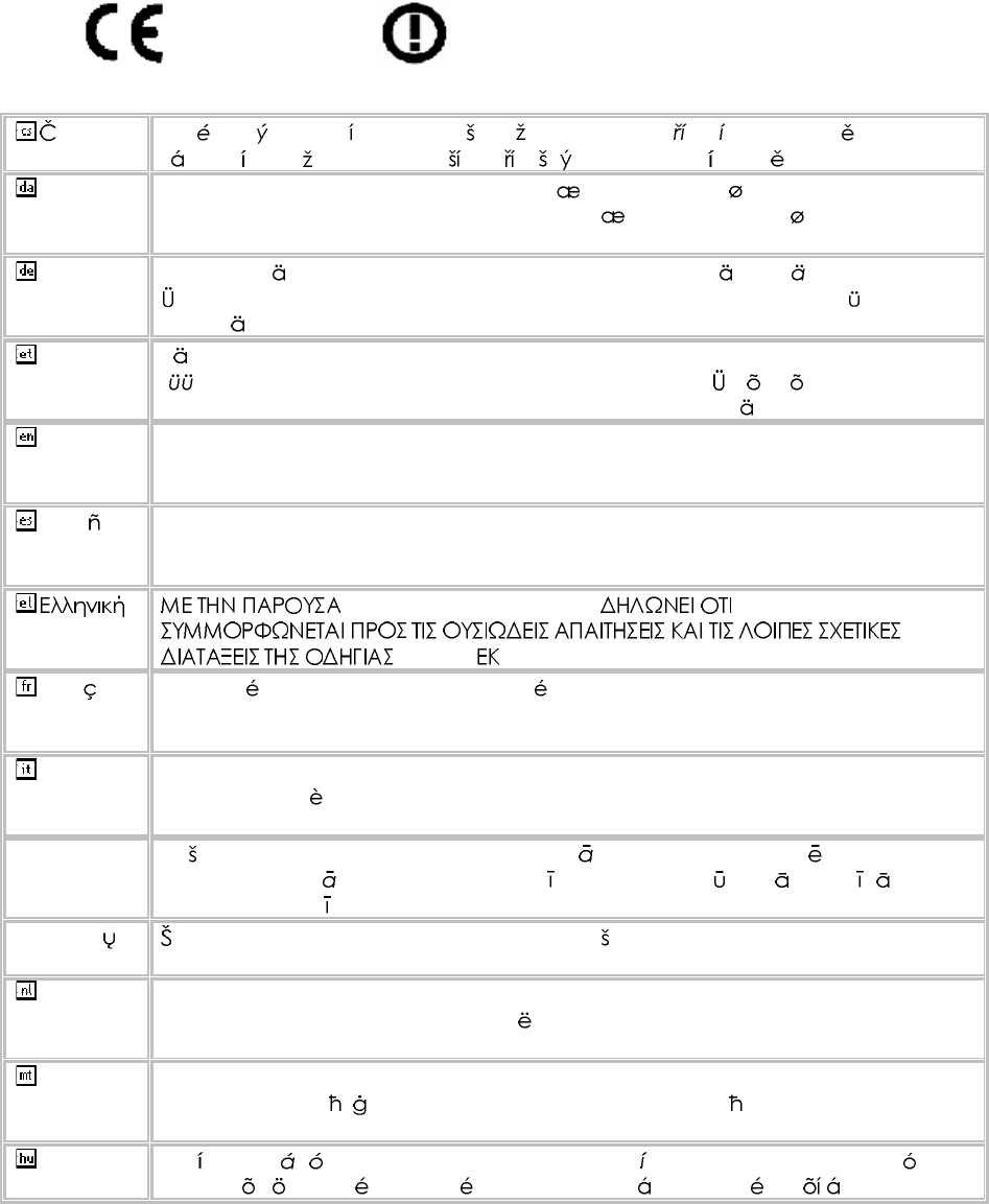
0560
esky
[Czech] [Jm no v robce] t mtoprohla uje, etento [typza zen ] jeveshod se
zkladnmipo adavkyadal mi p slu n miustanoven mism rnice1999/5/ES.
Dansk
[Danish] Undertegnede [fabrikantensnavn] erkl rerherved,at f lgendeudstyr
[udstyretstypebetegnelse] overholderde v sentligekrav og vrige relevante
kravidirektiv1999/5/EF.
Deutsch
[German] Hiermiterkl rt [NamedesHerstellers],dass sichdasGer t [Ger tetyp] in
bereinstimmungmitdengrundlegendenAnforderungenundden brigen
einschl gigenBestimmungenderRichtlinie1999/5/EGbefindet.
Eesti
[Estonian] Kesolevagakinnitab [tootja nimi= nameofmanufacturer] seadme [seadme
tp=typeofequipment] vastavustdirektiivi1999/5/E p hin ueteleja
nimetatuddirektiivisttulenevateleteisteleasjakohastele s tetele.
English Hereby, [nameofmanufacturer],declaresthatthis [type ofequipment] isin
compliancewiththeessentialrequirementsand otherrelevantprovisionsof
Directive1999/5/EC.
Espa ol
[Spanish] Pormediodelapresente [nombredelfabricante] declaraqueel [clasede
equipo] cumpleconlosrequisitosesencialesycualesquiera otrasdisposiciones
aplicables o exigiblesdela Directiva1999/5/CE.
[Greek] [nameofmanufacturer] [typeofequipment]
1999/5/ .
Fran ais
[French] Parlapr sente [nomdufabricant] d clarequel'appareil [typed'appareil] est
conformeauxexigencesessentiellesetauxautresdispositionspertinentesdela
directive1999/5/CE.
Italiano
[Italian] Conlapresente [nomedelcostruttore] dichiarachequesto [tipodi
apparecchio] conformeairequisitiessenzialiedallealtredisposizioni
pertinenti stabilitedalladirettiva1999/5/CE.
Latviski
[Latvian] Ar o [name ofmanufacturer/izgatavot janosaukums] deklar ,ka [type of
equipment/iek rtastips] atbilstDirektvas1999/5/EK b tiskaj mprasb mun
citiemarto saist tajiem noteikumiem.
Lietuvi
[Lithuanian] iuo [manufacturer name] deklaruoja,kad is [equipmenttype] atitinka
esminiusreikalavimusirkitas1999/5/EB Direktyvosnuostatas.
Nederlands
[Dutch]
Hierbijverklaart [naamvandefabrikant]dat hettoestel [typevantoestel] in
overeenstemmingismetdeessenti leeisenendeandere relevante
bepalingenvanrichtlijn1999/5/EG.
Malti
[Maltese] Hawnhekk, [isemtal-manifattur],jiddikjaralidan [il-mudeltal-prodott]
jikkonformamal- ti ijietessenzjaliumaprovvedimenti o rajnrelevantili hemm
fid-Dirrettiva1999/5/EC.
Magyar
[Hungarian] Alul rott, [gy rt neve] nyilatkozom,hogya[... tpus] megfelelavonatkoz
alapvet k vetelm nyeknek saz1999/5/ECir nyelvegy bel r sainak.
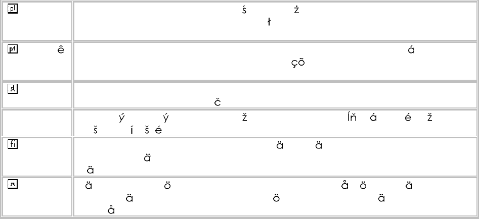
Polski
[Polish] Niniejszym [nazwaproducenta] o wiadcza, e [nazwa wyrobu] jestzgodnyz
zasadniczymiwymogamiorazpozosta ymistosownymipostanowieniami
Dyrektywy1999/5/EC.
Portugu s
[Portuguese
]
[Nomedofabricante] declaraqueeste [tipodeequipamento] est conforme
comos requisitosessenciaise outrasdisposi esda Directiva1999/5/CE.
Slovensko
[Slovenian] [Imeproizvajalca] izjavlja,dajeta [tip opreme] v skladuzbistvenimizahtevami
inostalimirelevantnimidolo ilidirektive1999/5/ES.
Slovensky
[Slovak] [Meno v robcu] t mtovyhlasuje, e [typzariadenia] sp a z kladn po iadavky
a v etkypr slu n ustanoveniaSmernice1999/5/ES.
Suomi
[Finnish] [Valmistaja=manufacturer] vakuuttaa t tenett [typeofequipment=laitteen
tyyppimerkint ] tyyppinenlaite on direktiivin1999/5/EY oleellistenvaatimustenja
sit koskeviendirektiivinmuidenehtojenmukainen.
Svenska
[Swedish] Hrmedintygar [f retag] attdenna [utrustningstyp] st rI verensst mmelse
medde v sentligaegenskapskrav och vrigarelevantabest mmelsersom
framg ravdirektiv1999/5/EG.

Ë
ÍÛÎ
Ù
Ë×ÜÛ
ÎÙíðð
WiMAX IEEE 802.16e Indoor Gateway
with 2.3 and 2.5 GHz Frequency Band Support,
Up to Four LAN (RJ-45) Ports,
Up to Two VoIP (RJ-11) Ports,
and Optional 802.11n Wi-Fi
Models with Wi-Fi
RG300
RG300-2.5
RG300-2.5-4D2V1W
RG300-2.5-4D1W
RG300-2.5-1D2V1W
RG300-2.5-1D1V1W
RG300-2.5-1D1W
RG300-2.3
RG300-2.3-4D2V1W
RG300-2.3-4D1W
RG300-2.3-1D2V1W
RG300-2.3-1D1V1W
RG300-2.3-1D1W
Models without Wi-Fi
RG300
RG300-2.5
RG300-2.5-4D2V
RG300-2.5-4D
RG300-2.5-1D1V
RG300-2.5-1D
RG300-2.3
RG300-2.3-4D2V
RG300-2.3-4D
RG300-2.3-1D1V
RG300-2.3-1D
(where D=LAN ports, V=VoIP ports, W=Wi-Fi)
RG300
E042011-CS-R01
149100000095W

3
ÝÑÓÐÔ×ßÒÝÛÍ
ÚÛÜÛÎßÔ ÝÑÓÓËÒ×ÝßÌ×ÑÒ ÝÑÓÓ×ÍÍ×ÑÒ ×ÒÌÛÎÚÛÎÛÒÝÛ ÍÌßÌÛÓÛÒÌ
This equipment has been tested and found to comply with the limits for a
Class B digital device, pursuant to Part 15 of the FCC Rules. These limits
are designed to provide reasonable protection against harmful interference
in a residential installation. This equipment generates, uses and can
radiate radio frequency energy and, if not installed and used in accordance
with the instructions, may cause harmful interference to radio
communications. However, there is no guarantee that interference will not
occur in a particular installation. If this equipment does cause harmful
interference to radio or television reception, which can be determined by
turning the equipment off and on, the user is encouraged to try to correct
the interference by one of the following measures:
Reorient or relocate the receiving antenna
Increase the separation between the equipment and receiver
Connect the equipment into an outlet on a circuit different from that to
which the receiver is connected
Consult the dealer or an experienced radio/TV technician for help
This device complies with Part 15 of the FCC Rules. Operation is subject to
the following two conditions: (1) This device may not cause harmful
interference, and (2) this device must accept any interference received,
including interference that may cause undesired operation.
FCC Caution: Any changes or modifications not expressly approved by the
party responsible for compliance could void the user's authority to operate
this equipment.
×ÓÐÑÎÌßÒÌ ÒÑÌÛæ
ÚÝÝ ÎßÜ×ßÌ×ÑÒ ÛÈÐÑÍËÎÛ ÍÌßÌÛÓÛÒÌ
This equipment complies with FCC radiation exposure limits set forth for an
uncontrolled environment. This equipment should be installed and
operated with minimum distance 20 cm between the radiator and your
body.
This transmitter must not be co-located or operating in conjunction with
any other antenna or transmitter.
Due to the essential high output power nature of WiMAX devices, use of
this device with other transmitters at the same time may exceed the FCC
RF exposure limit and such usage must be prohibited (unless such co-
transmission has been approved by FCC in the future).
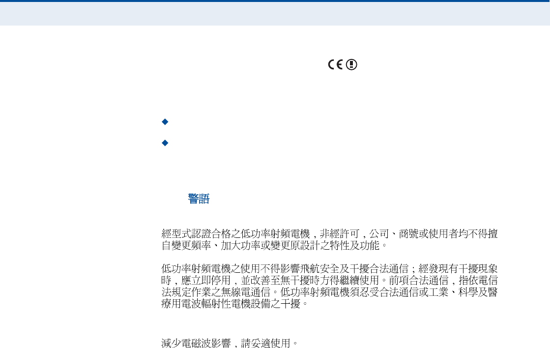
Ý
ÑÓÐÔ×ßÒÝÛÍ
4
ÛÝ ÝÑÒÚÑÎÓßÒÝÛ ÜÛÝÔßÎßÌ×ÑÒ
Marking by the above symbol indicates compliance with the Essential
Requirements of the R&TTE Directive of the European Union (1999/5/EC).
This equipment meets the following conformance standards:
EN 60950-1 (IEC 60950-1) - Product Safety
EN 301 489-1, EN 301 489-4, EN 302 326-2 (V1.2.2), EN 302 326-3
(V1.2.2) - EMC requirements for radio equipment
This device is intended for use in all European Community countries.
ÒÝÝ
Wi-Fi:
WiMAX:
5
ßÞÑËÌ ÌØ×Í ÙË×ÜÛ
ÐËÎÐÑÍÛ This guide details the hardware features of the RG300 WiMAX 802.16e
Indoor Gateway, including its physical and performance-related
characteristics, and how to install the device and use its configuration
software.
ßËÜ×ÛÒÝÛ This guide is for PC users with a working knowledge of computers. You
should be familiar with Windows operating system concepts.
ÝÑÒÊÛÒÌ×ÑÒÍ The following conventions are used throughout this guide to show
information:
Ò
ÑÌÛ
æ
Emphasizes important information or calls your attention to related
features or instructions.
Ý
ßËÌ×ÑÒ
æ
Alerts you to a potential hazard that could cause loss of data, or
damage the system or equipment.
É
ßÎÒ×ÒÙ
æ
Alerts you to a potential hazard that could cause personal injury.
ÎÛÔßÌÛÜ ÐËÞÔ×ÝßÌ×ÑÒÍ The following publication gives basic information on how to install and use
the WiMAX 802.16e Indoor Gateway.
Quick Installation Guide
Also, as part of the WiMAX 802.16e Indoor Gateway!s configuration
software, there is online help that describes all management features.
ÎÛÊ×Í×ÑÒ Ø×ÍÌÑÎÇ This section summarizes the changes in each revision of this guide.
ßÐÎ×Ô îðïï ÎÛÊ×Í×ÑÒ
This is the first revision of this guide. This guide is valid for software
version 1.0.2.0.

6
ÝÑÒÌÛÒÌÍ
ÝÑÓÐÔ×ßÒÝÛÍ í
ßÞÑËÌ ÌØ×Í ÙË×ÜÛ ë
ÝÑÒÌÛÒÌÍ ê
Ú×ÙËÎÛÍ ïð
ÌßÞÔÛÍ ïî
ÍÛÝÌ×ÑÒ × ÙÛÌÌ×ÒÙ ÍÌßÎÌÛÜ ïí
ï×ÒÌÎÑÜËÝÌ×ÑÒ ïì
RG300 Hardware Description 15
Wi-Fi Option 15
Power Status LED 16
Wi-Fi Status LED 17
WiMAX Signal LEDs 17
LAN Ports 17
VoIP Phone Ports 18
Power Adapter Socket 18
Reset Button 18
î×ÒÍÌßÔÔ×ÒÙ ÌØÛ ÎÙíðð îð
Package Checklist 20
Installation Overview 20
Select a Location 20
Cable Connections 21
í×Ò×Ì×ßÔ ÝÑÒÚ×ÙËÎßÌ×ÑÒ îí
Accessing the Web Management Interface 23
Home Page 24
Using the Basic Setup Wizard 25
The Advanced Setup Menu 27

Ý
ÑÒÌÛÒÌÍ
7
Common Web Page Buttons 28
ÍÛÝÌ×ÑÒ ×× ÉÛÞ ÝÑÒÚ×ÙËÎßÌ×ÑÒ îç
ìÍÇÍÌÛÓ ÍÛÌÌ×ÒÙÍ íð
System Status 31
Administrator Settings 32
Firmware Upgrade 33
Configuration Tools 34
System Time 35
System Log 36
Reset 37
ëÉßÒ ÝÑÒÚ×ÙËÎßÌ×ÑÒ íè
WAN Settings 39
Dynamic IP Address 40
Static IP Settings 40
L2TP Settings 41
PPTP Settings 41
DNS 42
DDNS 43
êÔßÒ ÝÑÒÚ×ÙËÎßÌ×ÑÒ ìì
LAN Settings 45
DHCP Client List 46
éÒßÌ ÝÑÒÚ×ÙËÎßÌ×ÑÒ ìé
NAT Settings 48
Port Mapping 49
DMZ 50
ALG 51
èÚ×ÎÛÉßÔÔ ÝÑÒÚ×ÙËÎßÌ×ÑÒ ëî
Firewall Settings 53
Client Filtering 54
Port Filtering 55
MAC Filtering 56
URL Filtering 57

Ý
ÑÒÌÛÒÌÍ
8
Host Filtering 58
çÎÑËÌ×ÒÙ ÝÑÒÚ×ÙËÎßÌ×ÑÒ ëç
Routing Table 60
Static Route 61
ïðËÐÒÐ ÝÑÒÚ×ÙËÎßÌ×ÑÒ êî
UPnP 63
ïïÊÑ×Ð ÍÛÌÌ×ÒÙÍ êì
SIP Account 65
SIP Settings 66
Speed Dial 67
Dial Plan 68
Call Feature 70
Phone Settings 72
Codecs 73
ïîÉ×óÚ× ÍÛÌÌ×ÒÙÍ éë
Basic Wireless Settings 76
Advanced Wireless Settings 78
Wireless Security 79
Wired Equivalent Privacy (WEP) 80
WPA Pre-Shared Key 81
ACL Settings 83
ïíÏÑÍ ÝÑÒÚ×ÙËÎßÌ×ÑÒ èì
QoS Settings 85
ÍÛÝÌ×ÑÒ ××× ßÐÐÛÒÜ×ÝÛÍ èê
ßÌÎÑËÞÔÛÍØÑÑÌ×ÒÙ èé
Diagnosing LED Indicators 87
Cannot Connect to the Internet 87
Cannot Access Web Management 88
Forgot or Lost the Password 88
Resetting the Unit 88
ÞØßÎÜÉßÎÛ ÍÐÛÝ×Ú×ÝßÌ×ÑÒÍ èç

Ý
ÑÒÌÛÒÌÍ
9
Physical Specifications 89
WiMAX Specifications 90
VoIP Specifications 90
Wi-Fi Specifications 91
Compliances 92
ÝÝßÞÔÛÍ ßÒÜ Ð×ÒÑËÌÍ çí
Twisted-Pair Cable Assignments 93
10/100BASE-TX Pin Assignments 93
Straight-Through Wiring 94
Crossover Wiring 95
RJ-11 Port 96
ÙÔÑÍÍßÎÇ çé
×ÒÜÛÈ ïðî

10
Ú×ÙËÎÛÍ
Figure 1:Front of the RG30015
Figure 2:RG300 LED Indicators 16
Figure 3:Back of the RG30018
Figure 4:Base of the RG30019
Figure 5:RG300 Connections 21
Figure 6:Login Page 23
Figure 7:Home Page 24
Figure 8:WiMAX Account Login 25
Figure 9:Confirm Settings 26
Figure 10:Setup Wizard Finished 26
Figure 11:Advanced Setup 27
Figure 12:Common Web Page Buttons 28
Figure 13:System Status Internet31
Figure 14:System Status Gateway31
Figure 15:System Status Information32
Figure 16:Setting a Password 32
Figure 17:Firmware Upgrade 33
Figure 18:Configuration Tools 34
Figure 19:Restore Configuration Settings 34
Figure 20:System Time 35
Figure 21:System Log 36
Figure 22:Reset Unit 37
Figure 23:WAN Settings 39
Figure 24:Dynamic IP Address 40
Figure 25:Static IP Settings 40
Figure 26:L2TP Settings 41
Figure 27:PPTP Settings 41
Figure 28:DNS Settings 42
Figure 29:DDNS Settings 43
Figure 30:LAN Settings 45
Figure 31:DHCP Client List 46

Ú
×ÙËÎÛÍ
11
Figure 32:NAT Settings 48
Figure 33:Port Mapping 49
Figure 34:DMZ Settings 50
Figure 35:ALG Settings 51
Figure 36:Firewall Settings 53
Figure 37:Client Filtering Settings 54
Figure 38:Port Filtering 55
Figure 39:MAC Filtering 56
Figure 40:URL Filtering 57
Figure 41:Host Filtering 58
Figure 42:Routing Table 60
Figure 43:Static Route 61
Figure 44:UPnP Setting 63
Figure 45:SIP Account Settings 65
Figure 46:SIP Settings 66
Figure 47:Speed Dial 67
Figure 48:Dial Plan Settings 68
Figure 49:Call Features 70
Figure 50:Phone Settings 72
Figure 51:VoIP Codecs 73
Figure 52:Wireless Settings 76
Figure 53:Advanced Wireless Settings 78
Figure 54:Security Mode Options 80
Figure 55:Security Mode - WEP 80
Figure 56:Security Mode - WPA-PSK 81
Figure 57:ACL Settings 83
Figure 58:QoS Settings 85
Figure 59:RJ-45 Connector 93
Figure 60:Straight Through Wiring 94
Figure 61:Crossover Wiring 95
Figure 62:RJ-11 Port Pinout 96

12
ÌßÞÔÛÍ
Table 1:Power Status LED 16
Table 2:Wi-Fi Status LED 17
Table 3:WiMAX Signal Status LEDs 17
Table 4:LAN Port Status LED 18
Table 5:Dial Plan Elements 68
Table 6:Troubleshooting Chart 87
Table 7:10/100BASE-TX MDI and MDI-X Port Pinouts 94
Table 8:RJ-11 Port Pinout 96

13
Í
ÛÝÌ×ÑÒ
×
ÙÛÌÌ×ÒÙ ÍÌßÎÌÛÜ
This section provides an overview of the RG300, and describes how to
install and mount the unit. It also describes the basic settings required to
access the management interface and run the setup Wizard.
This section includes these chapters:
"Introduction# on page14
"Installing the RG300# on page20
"Initial Configuration# on page23

14
ï×ÒÌÎÑÜËÝÌ×ÑÒ
The RG300 WiMAX 802.16e Indoor Gateway is a WiMAX subscriber station
designed to provide Internet access for a home or small office. The unit
provides a gateway function between a WiMAX service provider and a local
Ethernet LAN. The device enables a service provider to deliver last mile
broadband wireless access as an alternative to wired DSL or cable
modems.
The RG300 includes up to four RJ-45 Ethernet ports for LAN connections
and up to two RJ-11 Voice over IP (VoIP) phone ports. Units also support
an IEEE802.11b/g/n Wi-Fi module that provides a local Wi-Fi access point
service.
The RG300 offers a user-friendly web-based management interface for the
configuration of all the unit!s features. Any PC directly attached to the unit
can access the management interface using a web browser, such as
Internet Explorer (version 6.0 or above) or Firefox (version 1.5 or above).

Ý
ØßÐÌÛÎ
ï
| Introduction
RG300 Hardware Description
15
ÎÙíðð ØßÎÜÉßÎÛ ÜÛÍÝÎ×ÐÌ×ÑÒ
The front of the RG300 provides an array of system status indicators. The
back includes four LAN ports for 10/100 Mbps Ethernet connections, two
RJ-11 VoIP phone ports, and a DC power jack.
Figure 1: Front of the RG300
É×óÚ× ÑÐÌ×ÑÒ The RG300 includes an 802.11b/g/n Wi-Fi support. This unit includes
internal antennas for local wireless connections to PCs.
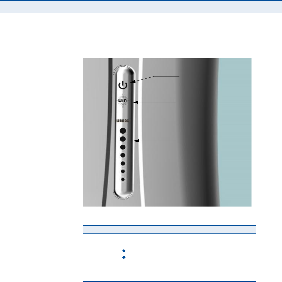
Ý
ØßÐÌÛÎ
ï
| Introduction
RG300 Hardware Description
16
ÐÑÉÛÎ ÍÌßÌËÍ ÔÛÜ The RG300 includes a Power LED indicator that simplifies installation and
WiMAX network troubleshooting. The LED, which is located on the front
panel, is described in the following table.
Figure 2: RG300 LED Indicators
Table 1: Power Status LED
Status Description
On GreenThe unit has completed entry to a WiMAX network.
On AmberIndicates one of the following conditions:
After power on, indicates the unit is running its self test.
Indicates that the network entry process is in progress or has
restarted.
On RedA system failure has occured.
OffNo power is being supplied to the unit.
Power Status LED
Wi-Fi Status LED
WiMAX Signal LEDs

Ý
ØßÐÌÛÎ
ï
| Introduction
RG300 Hardware Description
17
É×óÚ× ÍÌßÌËÍ ÔÛÜ The RG300 includes a Wi-Fi LED indicator that displays the Wi-Fi network
status. The LED, which is located on the front panel, is described in the
following table.
É×ÓßÈ Í×ÙÒßÔ ÔÛÜÍThe RG300 includes seven WiMAX signal strength LED indicators that
display the current WiMAX receive signal status. The LEDs, which are
located on the front panel, are described in the following table.
ÔßÒ ÐÑÎÌÍ The RG300 provides up to four 10BASE-T/100BASE-TX RJ-45 ports. The
LAN ports are standard RJ-45 Ethernet network ports that connect directly
to a PC. They can also be connected to an Ethernet switch or hub to
support more users.
The RJ-45 ports support automatic MDI/MDI-X operation, so you can use
straight-through cables for all network connections to PCs or servers, or to
other switches or hubs. The port supports auto-negotiation, so the
optimum transmission mode (half or full duplex), and data rate (10 or
100Mbps) is selected automatically.
Table 2: Wi-Fi Status LED
Status Description
On GreenThe Wi-Fi radio is enabled and operating normally.
Flashing GreenIndicates data traffic in the Wi-Fi network.
OffThere is no Wi-Fi connection or the radio is disabled.
Table 3: WiMAX Signal Status LEDs
LED Status Description
1 On BlueIndicates the receive signal is 5 dB or more.
2 On BlueIndicates the receive signal is 8 dB or more.
3 On BlueIndicates the receive signal is 12 dB or more.
4 On BlueIndicates the receive signal is 15 dB or more.
5 On BlueIndicates the receive signal is 18 dB or more.
6 On BlueIndicates the receive signal is 20 dB or more.
7 On BlueIndicates the receive signal is 25 dB or more.
1-7 in sequenceOn BlueThe unit is scanning frequency channels.
All 7 LEDsOffNo power is being supplied to the unit.

Ý
ØßÐÌÛÎ
ï
| Introduction
RG300 Hardware Description
18
Figure 3: Back of the RG300
The RJ-45 ports include a built-in LED status indicator. This LED indicator is
described in the following table.
ÊÑ×Ð ÐØÑÒÛ ÐÑÎÌÍ The RG300 also provides up to two RJ-11 telephone ports that connect
directly to a standard (analog) telephone set. This allows a regular
telephone to be used for making VoIP calls over the Internet.
ÐÑÉÛÎ ßÜßÐÌÛÎ
ÍÑÝÕÛÌ
The power socket is located on the rear panel of the RG300. The power
socket is for the AC power adapter connection.
The unit is powered on when connected to its AC power adapter, and the
power adapter is connected to an AC power source between 100-240 volts
at 50-60Hz.
ÎÛÍÛÌ ÞËÌÌÑÒ The Reset button is located on the base of the RG300 and is used to reset
the unit or restore the factory default configuration. If you press the button
for less than 1 second, the unit will perform a hardware reset. If you press
and hold down the button for 5 seconds or more, any configuration
Table 4: LAN Port Status LED
LED Status Description
Link/ActivityOn GreenEthernet port has a valid link with an attached device.
Flashing GreenThe port is transmitting or receiving data.
OffEthernet port has no link with another device.
RJ-45 LAN Ports
(includes Link/Activity LED) VoIP Phone Ports Power Socket
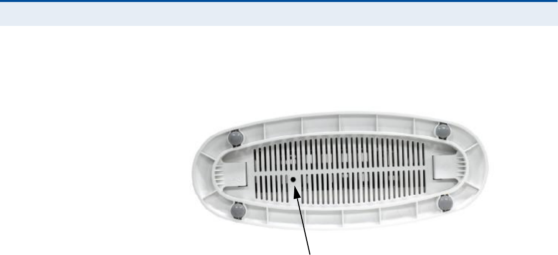
Ý
ØßÐÌÛÎ
ï
| Introduction
RG300 Hardware Description
19
changes you may have made are removed, and the factory default
configuration is restored to the unit.
Figure 4: Base of the RG300
Reset Button

20
î×ÒÍÌßÔÔ×ÒÙ ÌØÛ ÎÙíðð
This section describes how to install and connect the RG300 WiMAX
802.16e Indoor Gateway.
ÐßÝÕßÙÛ ÝØÛÝÕÔ×ÍÌ
The RG300 package includes:
RG300 unit (RG300-2.3 or RG300-2.5)
RJ-45 Category 5 network cable
AC power adapter
Quick Installation Guide
User Guide CD
×ÒÍÌßÔÔßÌ×ÑÒ ÑÊÛÎÊ×ÛÉ
Before installing the RG300, verify that you have all the items listed in the
package checklist above. If any of the items are missing or damaged,
contact your local dealer. Also, be sure you have all the necessary tools and
cabling before installing the RG300.
ÍÛÔÛÝÌ ß ÔÑÝßÌ×ÑÒ
The RG300 can be installed indoors on any horizontal surface, such as a
desktop or shelf.
When selecting a suitable location for the device, consider these
guidelines:
Select a cool, dry place, which is out of direct sunlight.
The device should have adequate space (approximately two inches) on
all sides for proper air flow.
The device must be near an AC power outlet that provides 100 to
240V, 50 to 60Hz.
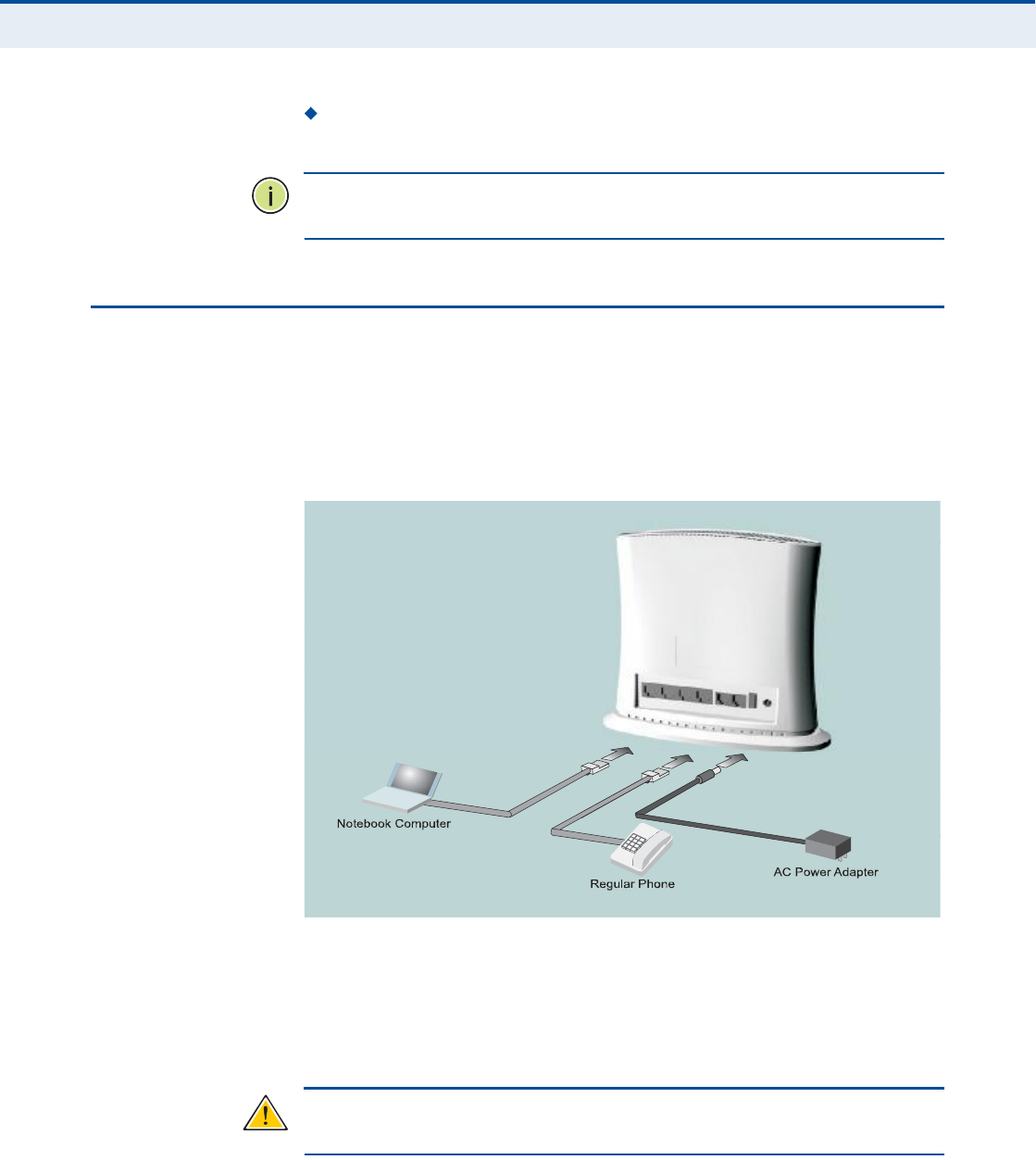
Ý
ØßÐÌÛÎ
î
| Installing the RG300
Cable Connections
21
The device should be accessible for network cabling and allow the
status LED indicators to be clearly visible.
Ò
ÑÌÛ
æ
If the RG300 displays a weak WiMAX receive signal, try moving it to
another location.
ÝßÞÔÛ ÝÑÒÒÛÝÌ×ÑÒÍ
The RG300 is a plug-and-play device, so once it has been connected to
your PC and powered up, it is fully operable.
Functioning as a gateway, the unit routes traffic between a WiMAX service
provider!s base station and PCs or notebooks in the local network.
Figure 5: RG300 Connections
To connect the RG300, follow these steps:
ïò Power on the RG300 by by first connecting the AC power adapter to the
unit!s power socket, and then connecting the adapter to an AC power
source.
Ý
ßËÌ×ÑÒ
æ
Use ONLY the power adapter supplied with the RG300. Otherwise,
the product may be damaged.
Ò±¬»¾±±µ ݱ³°«¬»®
λ¹«´¿® и±²»
ßÝ Ð±©»®ß¼¿°¬»®

Ý
ØßÐÌÛÎ
î
| Installing the RG300
Cable Connections
22
îò Observe the Indicator LEDs. When you power on the RG300, verify that
the Power LED turns on and that the other LED indicators start
functioning as described under "RG300 Hardware Description# on
page15.
íò Connect Category 5 or better Ethernet cables from the RG300!s LAN
ports to the network ports of your PCs. Alternatively, you can connect
the LAN port to an Ethernet switch or other device. Make sure the
length of each cable does not exceed 100 meters (328 ft).
If a PC is powered on, the RJ-45 LAN port LED on the RG300 will turn
on to indicate a valid link.
ìò (Optional) Connect a standard (analog) telephone set to one of the
RG300!s VoIP ports using standard telephone cable with RJ-11 plugs.
The RG300 enables VoIP calls to be made through the unit using a
standard (analog) telephone set connected to the VoIP port, or from
PCs or other network devices connected to the LAN ports. Standard
Session Initiation Protocol (SIP) technology is used to make VoIP calls.
You must access the web interface and configure settings for your SIP
service provider before being able to make VoIP calls.
ëò Use your PC!s web browser to access the unit!s management interface
and run the Setup Wizard to make any configuration changes. For more
information, see Chapter 3, "Initial Configuration.#
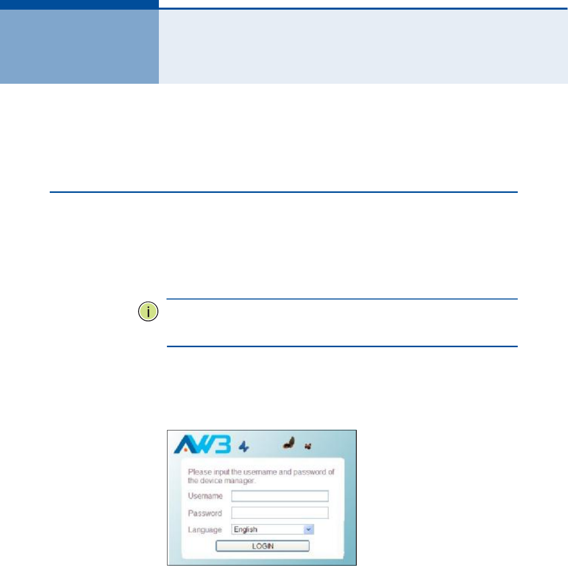
23
í×Ò×Ì×ßÔ ÝÑÒÚ×ÙËÎßÌ×ÑÒ
The RG300 initial configuration steps can be made through its web
management interface using the Setup Wizard. It is recommended to make
the initial changes by connecting a PC directly to one of the RG300!s LAN
ports.
ßÝÝÛÍÍ×ÒÙ ÌØÛ ÉÛÞ ÓßÒßÙÛÓÛÒÌ ×ÒÌÛÎÚßÝÛ
The RG300 has a default IP address of 192.168.1.1 and a subnet mask of
255.255.255.0. If your PC is set to have an IP address assigned by DHCP
(Dynamic Host Configuration Protocol), you can connect immediately to the
web management interface. Otherwise, you must first check if your PC!s IP
address is set on the same subnet as the RG300 (that is, the PC!s IP
address starts 192.168.1.x).
Ò
ÑÌÛ
æ
If your RG300 unit is not configured with the standard default IP
address and login Username/Password, use the default values on the label
affixed to the unit.
In the web browser!s address bar, type the default IP address: http://
192.168.1.1.
The web browser displays the RG300!s login page.
Figure 6: Login Page
Logging In Type the default User Name "admin# and Password "admin,#
then click Login. The home page displays.

Ý
ØßÐÌÛÎ
í
| Initial Configuration
Accessing the Web Management Interface
24
Language Selects English or Traditional Chinese as the web interface
language.
Ò
ÑÌÛ
æ
It is recommended that you configure a user password as the first
step under "Administrator Settings# on page32 to control management
access to the unit.
ØÑÓÛ ÐßÙÛ The home page displays the current status of the WiMAX connection.
To configure basic settings for the current operating mode, click Basic
Setup. For more information, see "Using the Basic Setup Wizard# on
page25.
Alternatively, to configure more detailed settings, click Advanced Setup.
For more information, see "The Advanced Setup Menu# on page27.
Figure 7: Home Page
The following parameters are displayed on the home page:
Username Describes the WiMAX network login name.
Operator Name The identity of the operator network.
Base Station ID The identifier of the connected base station.
Preamble Index A number that identifies the sector on the
connected base station.
Signal Strength The current signal strength value of the received
WiMAX radio signal.

Ý
ØßÐÌÛÎ
í
| Initial Configuration
Using the Basic Setup Wizard
25
Signal Quality An indication of the carrier-to-interference-plus-
noise-ratio (CINR), which measures the strength of the receive signal
compared to other interference and noise.
Connection Status The current status of the WiMAX connection.
Central Frequency The center frequency of the WiMAX signal.
Bandwidth The bandwidth of the WiMAX signal.
ËÍ×ÒÙ ÌØÛ ÞßÍ×Ý ÍÛÌËÐ É×ÆßÎÜ
The Basic Setup Wizard takes you through the basic configuration steps for
the RG300.
Launching the Basic Setup Wizard To perform basic configuration,
click Basic Setup on the home page.
When configuring the unit through the Setup Wizard you will need to
proceed through the following steps:
ïò WiMAX Account Login Configures user authentication settings for
connection to the WiMAX network.
Figure 8: WiMAX Account Login
The following parameters are displayed on this page:
Username The user name required for authentication as
provided by the WiMAX operator.
Preview Displays the current user account that will be used.

Ý
ØßÐÌÛÎ
í
| Initial Configuration
Using the Basic Setup Wizard
26
Password The user password required for authentication as
provided by the WiMAX operator.
îò Apply Settings Click "Confirm# to apply the basic settings.
Figure 9: Confirm Settings
íò Basic Setup Finished When the Basic Setup steps are completed
the unit reboots and attempts to connect to the specified WiMAX
network. Log in again to return to the Home page.
Figure 10: Setup Wizard Finished
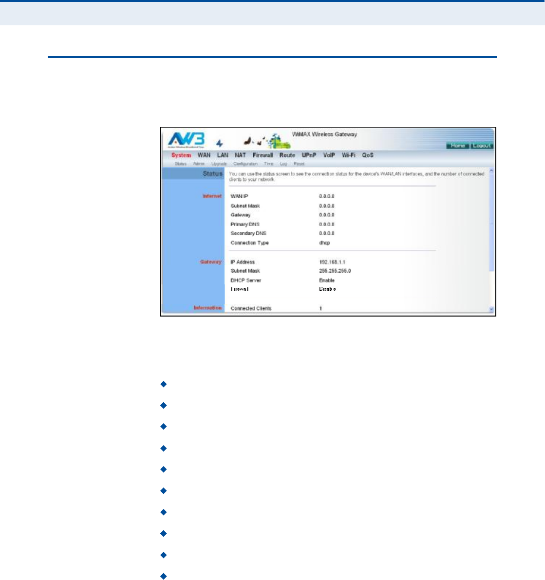
Ý
ØßÐÌÛÎ
í
| Initial Configuration
The Advanced Setup Menu
27
ÌØÛ ßÜÊßÒÝÛÜ ÍÛÌËÐ ÓÛÒË
The Advanced Setup menu provides access to all the configuration settings
available for the RG300.
Figure 11: Advanced Setup
Each primary menu item is sumarized below with links to the relevant
section in this guide where configuration parameters are described in
detail:
System Configures general device settings. See page30.
WAN Configures WAN settings. See page38.
LAN Configures LAN settings. See page44.
NAT Configures Network Address Translation settings. See page47.
Firewall Configures firewall settings. See page52.
Route Configures static routing settings. See page59.
UPnP Enables UPnP. See page62.
VoIP Configures VoIP SIP settings. See page64.
Wi-Fi Configures Wi-Fi settings. See page75.
QoS Configures QoS settings. See page84.

Ý
ØßÐÌÛÎ
í
| Initial Configuration
Common Web Page Buttons
28
ÝÑÓÓÑÒ ÉÛÞ ÐßÙÛ ÞËÌÌÑÒÍ
The web management interface includes some common buttons that are
displayed at the top of each page.
Figure 12: Common Web Page Buttons
The list below describes these common buttons:
Apply $ Applies all new configuration changes on the current page and
saves them to memory.
Home $ Returns to the web management home page.
Logout $ Immediately closes the current web management session.
Reboot $ The Reboot button appears after some configuration
changes that require the Gateway to be reset. You can make as many
changes as you want before restarting the Gateway. All changes are
saved as they are made, but do not become active until after a restart.

29
Í
ÛÝÌ×ÑÒ
××
ÉÛÞ ÝÑÒÚ×ÙËÎßÌ×ÑÒ
This section provides details on configuring the RG300 using the web
browser interface.
This section includes these chapters:
"System Settings# on page30
"WAN Configuration# on page38
"LAN Configuration# on page44
"NAT Configuration# on page47
"Firewall Configuration# on page52
"Routing Configuration# on page59
"UPnP Configuration# on page62
"VoIP Settings# on page64
"Wi-Fi Settings# on page75
"QoS Configuration# on page84

30
ìÍÇÍÌÛÓ ÍÛÌÌ×ÒÙÍ
The RG300!s System menu allows you to perform general management
functions for the unit, including setting the system time, configuring an
access password, and upgrading the system software.
The System configuration pages include the following options:
"System Status# on page31
"Administrator Settings# on page32
"Firmware Upgrade# on page33
"Configuration Tools# on page34
"System Time# on page35
"System Log# on page36
"Reset# on page37
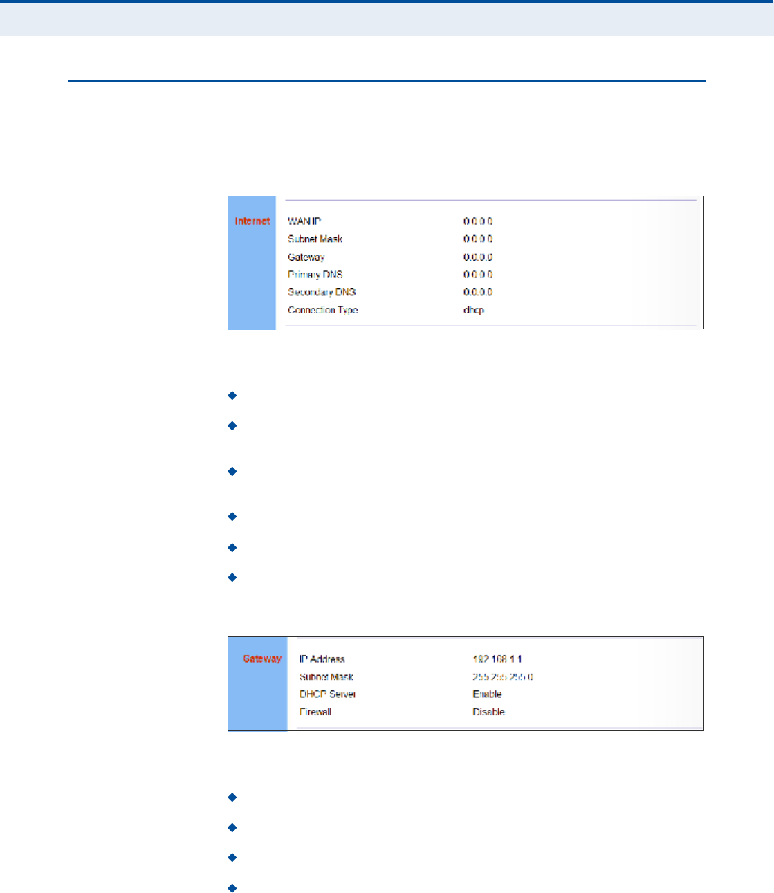
Ý
ØßÐÌÛÎ
ì
| System Settings
System Status
31
ÍÇÍÌÛÓ ÍÌßÌËÍ
The system status page displays connectivity status information for the
unit!s WiMAX (WAN) and LAN interfaces, and the number of clients
connected to the network.
Figure 13: System Status Internet
Internet Displays WAN (WiMAX) connection status:
WAN IP Displays the IP address assigned by the service provider.
Subnet Mask Displays the WAN subnet mask assigned by the service
provider.
Gateway Displays the WAN gateway address assigned by the service
provider.
Primary DNS Displays the WAN primary DNS address.
Secondary DNS Displays the WAN secondary DNS address.
Connection Type Displays the connection type for the WAN. Either
"fixed# for a static IP setting, or "dhcp# for dynamic IP assignment.
Figure 14: System Status Gateway
Gateway Display system IP settings, DHCP server, and firewall status:
IP Address Displays the unit!s IP address.
Subnet Mask Displays the subnet mask.
DHCP Server Displays the DHCP server status.
Firewall Displays the firewall status.

Ý
ØßÐÌÛÎ
ì
| System Settings
Administrator Settings
32
Figure 15: System Status Information
Information Displays the number of connected clients, as well as the
unit!s LAN and WAN MAC addresses:
Connected Clients Displays the number of connected clients, if any.
LAN MAC Address Displays the LAN MAC address.
LAN MTU Size The maximum transmission unit size in bytes.
WAN MAC Address Displays WAN MAC address.
WAN MTU Size The maximum transmission unit size in bytes.
ßÜÓ×Ò×ÍÌÎßÌÑÎ ÍÛÌÌ×ÒÙÍ
The Administrator Settings page enables you to change the password for
management access to the RG300.
Figure 16: Setting a Password
The following parameters are displayed on this page:
Current Password You need to first enter your current administrator
password to be able to configure a new one. (Default: admin)
Ò
ÑÌÛ
æ
If your RG300 unit is not configured with the standard default login
Username/Password, use the default values on the label affixed to the unit.
New Password Enter a new administrator password. (Range: 3~12
characters)

Ý
ØßÐÌÛÎ
ì
| System Settings
Firmware Upgrade
33
Confirm New Password Enter the new password again for
verification. (Range: 3~12 characters)
Language Selects English or Traditional Chinese as the web interface
language.
Ú×ÎÓÉßÎÛ ËÐÙÎßÜÛ
The Firmware Upgrade page enables you to download new software to the
unit.
Figure 17: Firmware Upgrade
The following parameters are displayed on this page:
Upgrade Downloads an operation code file from the web
management station to the RG300 using HTTP. Use the Browse button
to locate the code file locally on the management station and check the
Reset Configuration to restore factory defaults. Click Apply to proceed.
Auto Upgrade Provides a method to automatically upgrade the
Gateway when new code is available, as indicated by the contents of an
information file provided by the WiMAX service operator. The Auto
Upgrade information file and code file can be located on the same
server or different servers.
Enable Enables the automatic upgrade feature.
Update Interval A time interval (in seconds) for checking the
Info URL for new software information.
Limit Rate Places a limit on the firmware download rate from the
server.
Info URL A text string that indicates the location of an Auto
Upgrade information file on an FTP server. The file contains
information on the version of software available, and the FTP server
on which it is located. (For example: ftp://192.168.1.16/
autoupgrade/RG300-autoupgrade.info)
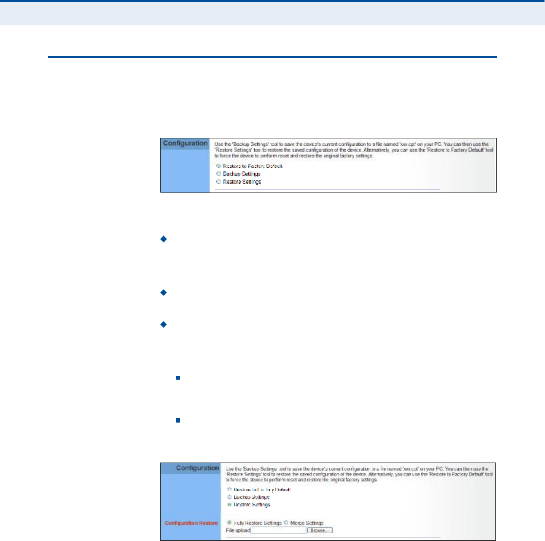
Ý
ØßÐÌÛÎ
ì
| System Settings
Configuration Tools
34
ÝÑÒÚ×ÙËÎßÌ×ÑÒ ÌÑÑÔÍ
The Configurations Tools page allows you to restore factory default
settings, or save and restore the unit!s configuration settings to or from a
file on the management station.
Figure 18: Configuration Tools
The following parameters are displayed on this page:
Restore Factory Default Configuration Resets the unit to its
factory default settings. When you select "Restore Factory Default
Configuration# and click Apply, a confirmation page displays. Click OK
to continue.
Backup Settings Saves the current configuration settings to a file on
the web management station.
Restore Settings Restores a saved configuration file to the unit.
Configuration files are plain-text files that can be edited directly to
modify settings (not all parameters need be defined). You can use the
Browse button to locate the file on the web management station.
Fully Restore Settings Restores all settings that are defined in
the uploaded configuration file. Any undefined settings are returned
to factory defaults.
Merge Settings Restores defined settings in the uploaded
configuration file. All other undefined settings are not changed.
Figure 19: Restore Configuration Settings
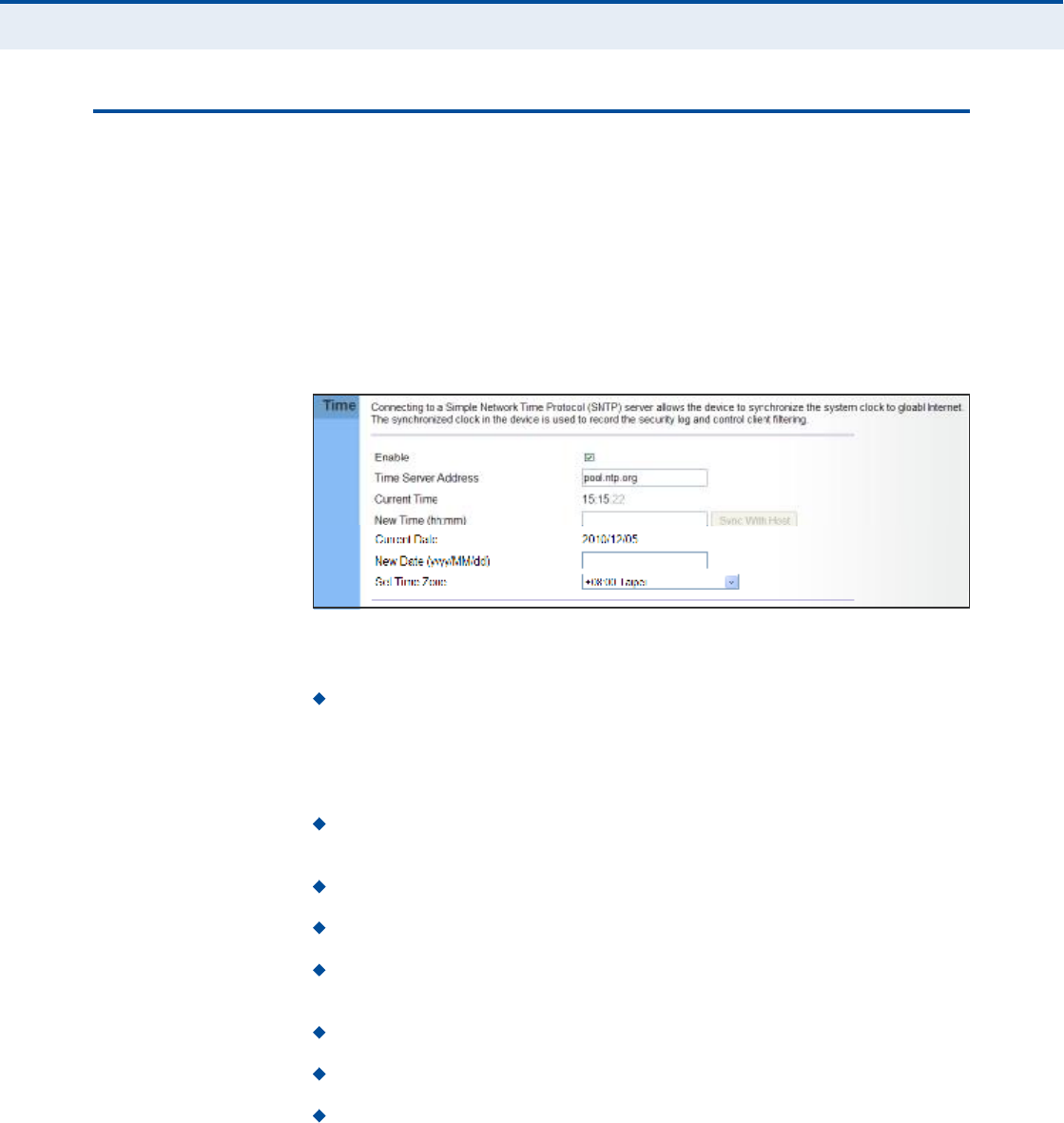
Ý
ØßÐÌÛÎ
ì
| System Settings
System Time
35
ÍÇÍÌÛÓ Ì×ÓÛ
The RG300 uses the Simple Network Time Protocol (SNTP) to set its
internal clock based on periodic updates from a time server. Maintaining an
accurate time on the device enables the system log to record meaningful
dates and times for event entries.
SNTP uses Coordinated Universal Time (or UTC, formerly Greenwich Mean
Time, or GMT) based on the time at the Earth!s prime meridian, zero
degrees longitude. To display a time corresponding to your local time, you
must select your time zone.
Figure 20: System Time
The following parameters are displayed on this page:
Enable Enables the unit to set its internal clock based on periodic
updates from a time server. The unit acts as an SNTP client, periodically
sending time synchronization requests to a specified time server.
Alternatively, you can select "None# and set the time and date
manually.
Time Server Address The IP address of a time server that the unit
attempts to poll for a time update.
Current Time (hh:mm:ss) The current time of the system clock.
New Time (hh:mm:ss) Sets the system clock to the time specified.
Sync with host Sets the unit!s time from the web management PC!s
system time.
Current Date (yyyy:mm:dd) The current date of the system clock.
New Date (yyyy:mm:dd) Sets the system clock date.
Set Time Zone SNTP uses Coordinated Universal Time (or UTC,
formerly Greenwich Mean Time, or GMT) based on the time at the
Earth!s prime meridian, zero degrees longitude. To display a time
corresponding to your local time, you must select your time zone from
the pull-down list.

Ý
ØßÐÌÛÎ
ì
| System Settings
System Log
36
ÍÇÍÌÛÓ ÔÑÙ
The RG300 supports a logging process that controls error messages saved
to memory. The logged messages serve as a valuable tool for isolating
device and network problems. The System Log page displays the latest
messages logged in chronological order, from the oldest to the newest. Log
messages saved in the unit!s memory are erased when the device is
rebooted.
Figure 21: System Log
The following items are displayed on this page:
Refresh $ Sends a request to add the latest entries to the System Log
Table.
Download $ Downloads the current system log messages to a file on
the web management station.
Clean $ Removes all the current system log messages from the
System Log Table.
System Log Level $ Sets the minimum severity level for event
logging. The system allows you to limit the messages that are logged
by specifying a minimum severity level. Error message levels range
from the most severe (Emergency) to least severe (Debug). The
message levels that are logged include the specified minimum level up
to the Emergency level.
Max Size $ The maximum memory size to be used for log messages
on the Gateway. (Range: 1-512 KB)
Set $ Click to set the Max Size and System Log Level values.

Ý
ØßÐÌÛÎ
ì
| System Settings
Reset
37
ÎÛÍÛÌ
The Reset page allows you to restart the device!s software. If the unit stops
responding correctly or in some way stops functioning, performing a reset
can clear the condition.
Figure 22: Reset Unit
Reset Resets the unit. All current settings are retained.

38
ëÉßÒ ÝÑÒÚ×ÙËÎßÌ×ÑÒ
The information in this chapter covers the configuration options for the
RG300!s WAN connection.
The WAN configuration pages include the following options:
"WAN Settings# on page39
"DNS# on page42
"DDNS# on page43
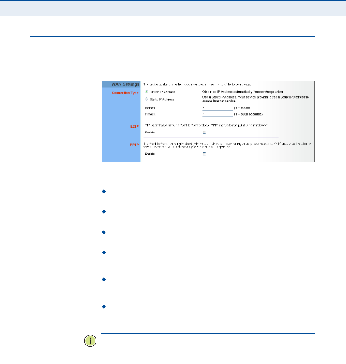
Ý
ØßÐÌÛÎ
ë
| WAN Configuration
WAN Settings
39
ÉßÒ ÍÛÌÌ×ÒÙÍ
Select the WAN connection type used by your service provider and specify
DNS (Domain Name System) servers.
Figure 23: WAN Settings
The unit can be connected to your ISP in one of the following ways:
DHCP IP Address Selects configuration for an Internet connection
using DHCP for IP address assignment.
Static IP Address Selects configuration for an Internet connection
using a fixed IP assignment.
Retries The maximum number of times the Gateway sends a DHCP
request to a DHCP server. (Range: 1-10000)
Timeout The maximum time period (in seconds) the Gateway waits
for a response from a DHCP server before it resends a request.
(Range: 1-3600 seconds)
L2TP Selects configuration for an Internet connection using the Layer
2 Tunneling Protocol, an access protocol often used for virtual private
networks.
PPTP Selects configuration for an Internet connection using the
Point-to-Point Tunneling Protocol, an access protocol often used for
virtual private networks.
Ò
ÑÌÛ
æ
For the Dynamic IP Address (DHCP) option, the unit requires no
further configuration. Selecting other WAN types displays the parameters
that are required for configuring the connection.
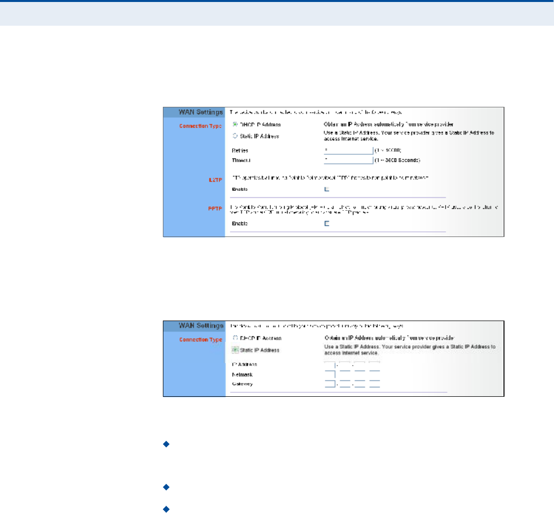
Ý
ØßÐÌÛÎ
ë
| WAN Configuration
WAN Settings
40
ÜÇÒßÓ×Ý ×Ð ßÜÜÎÛÍÍ For dynamic IP assignment from the service provider, the unit functions as
a Dynamic Host Configuration Protocol (DHCP) client. When enabled, no
other settings are required.
Figure 24: Dynamic IP Address
ÍÌßÌ×Ý ×Ð ÍÛÌÌ×ÒÙÍ Selecting Static IP Address for the WAN type enables you to enter static IP
settings as assigned by the service provider.
Figure 25: Static IP Settings
The following parameters are displayed in this section on this page:
IP Address The IP address provided by your service provider. Valid
IP addresses consist of four decimal numbers, 0 to 255, separated by
periods.
Netmask Indicates the subnet mask, such as 255.255.255.0.
Gateway The gateway IP address provided by your service provider.

Ý
ØßÐÌÛÎ
ë
| WAN Configuration
WAN Settings
41
ÔîÌÐ ÍÛÌÌ×ÒÙÍ If your service provider supports Layer 2 Tunneling Protocol (L2TP) for your
Internet connection, configure the settings described below.
Figure 26: L2TP Settings
The following parameters are displayed in this section on this page:
Enable Enables the L2TP settings.
Server IP The IP address of the L2TP server, as specified by the
service provider.
Username Enter your user name for connecting to the L2TP service,
as supplied by the service provider. (Range: 1-20 characters)
Password Specify the password for your connection, as supplied by
the service provider. (Range: 1-20 characters)
ÐÐÌÐ ÍÛÌÌ×ÒÙÍ If your service provider supports Point-to-Point Tunneling Protocol (PPTP)
for your Internet connection, configure the settings described below.
Figure 27: PPTP Settings
The following parameters are displayed in this section on this page:
Enable Enables the PPTP settings.
Server IP The IP address of the PPTP server, as specified by the
service provider.
Username Enter your user name for connecting to the PPTP service,
as supplied by the service provider. (Range: 1-20 characters)
Password Specify the password for your PPTP connection, as
supplied by the service provider. (Range: 1-20 characters)
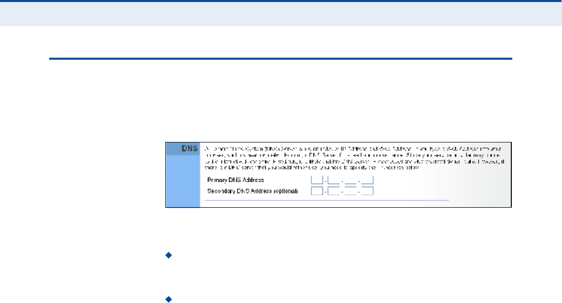
Ý
ØßÐÌÛÎ
ë
| WAN Configuration
DNS
42
ÜÒÍ
DNS (Domain Name System) server addresses are usually provided by
service providers, however if you want to specify certain servers, the DNS
page enables you to enter primary and secodary DNS addresses.
Figure 28: DNS Settings
The following parameters are displayed on this page:
Primary DNS Address Address of the primary DNS server, specified
in the form of 0.0.0.0. (The address 0.0.0.0 disables the manual DNS
setting.)
Secondary DNS Address (optional) Optional address of a
secondary DNS server, specified in the form of 0.0.0.0.
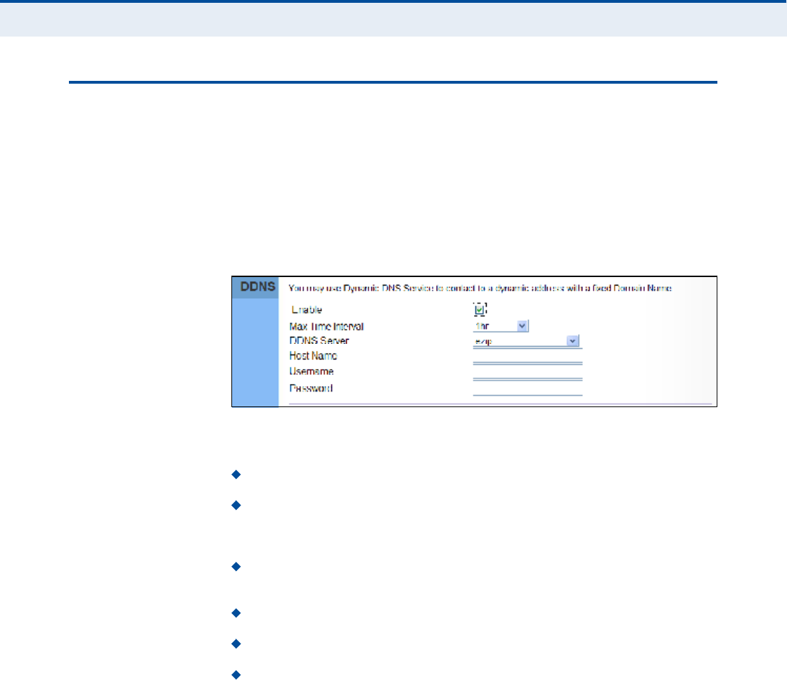
Ý
ØßÐÌÛÎ
ë
| WAN Configuration
DDNS
43
ÜÜÒÍ
Dynamic DNS (DDNS) provides users on the Internet with a method to tie
a specific domain name to the unit!s dynamically assigned IP address.
DDNS allows your domain name to follow your IP address automatically by
changing your DNS records when your IP address changes.
The RG300 provides access to a number DDNS service providers, such as
DynDns.org, Easydns.com, and ZoneEdit.com. To set up an DDNS account,
visit the website of one of the supported service providers.
Figure 29: DDNS Settings
The following items are displayed in this section on this page:
Enable $ Enables the DDNS service.
Max Time Interval $ The maximum time period before the Gateway
sends an update to the DDNS provider. (Options: 1hr, 3hr, 6hr, 8hr,
12hr, 1day, 3days, 1week)
DDNS Server $ Specifies the DDNS service provider, DynDns.org,
Freedns.afraid.org, ZoneEdit.com or Non-IP.com.
Host Name $ Specifies the URL of the DDNS service.
User Name ! Specifies your user name for the DDNS service.
Password $ Specifies your password for the DDNS service.

44
êÔßÒ ÝÑÒÚ×ÙËÎßÌ×ÑÒ
The information in this chapter covers the configuration options for the
RG300!s LAN functions.
The LAN configuration pages include the following options:
"LAN Settings# on page45
"DHCP Client List# on page46

Ý
ØßÐÌÛÎ
ê
| LAN Configuration
LAN Settings
45
ÔßÒ ÍÛÌÌ×ÒÙÍ
The RG300 must have a valid IP address for management using a web
browser and to support other features. The unit has a standard default IP
address of 192.168.1.1. You can use this IP address or assign another
address that is compatible with your existing local network. The unit can
also be enabled as a Dynamic Host Configuration Protocol (DHCP) server to
allocate IP addresses to local PCs.
Ò
ÑÌÛ
æ
If your RG300 unit is not configured with the standard default IP
address, use the default value on the label affixed to the unit.
The RG300 includes a DHCP server that can assign temporary IP addresses
to any attached host requesting the service. Addresses are assigned to
clients from a common address pool configured on the unit. Configure an
address pool by specifying start and end IP addresses. Be sure not to
include the unit's IP address in the address pool range.
Figure 30: LAN Settings
The following parameters are displayed on this page:
IP Address The IP address of the unit. Valid IP addresses consist of
four decimal numbers, 0 to 255, separated by periods. The standard
default setting is 192.168.1.1.
Subnet Mask Indicates the local IP subnet mask. The default setting
is 255.255.255.0.
The Gateway acts as DHCP Server Check this box to enable the
DHCP server.
IP Pool Starting/Ending Address Specifies the start and end IP
address of a range that the DHCP server can allocate to DHCP clients.
You can specify a single address or an address range. Note that the
address pool range must be in the same subnet as the unit!s IP setting.
Lease Time Selects a time limit for the use of an IP address form the
IP pool. When the time limit expires, the client has to request a new IP
address. (Options: 1hr, 3hr, 6hr, 8hr, 12hr, 1 day, 3days, 1 week)

Ý
ØßÐÌÛÎ
ê
| LAN Configuration
DHCP Client List
46
ÜØÝÐ ÝÔ×ÛÒÌ Ô×ÍÌ
The DHCP Client List page enables you to see the MAC address of devices
that are currently connected to the unit and have been assigned an IP
address by the DHCP server.
Figure 31: DHCP Client List

47
éÒßÌ ÝÑÒÚ×ÙËÎßÌ×ÑÒ
The information in this chapter covers the configuration options for the
RG300!s Network Address Translation (NAT) functions.
The NAT configuration pages include the following options:
"NAT Settings# on page48
"Port Mapping# on page49
"DMZ# on page50
"ALG# on page51

Ý
ØßÐÌÛÎ
é
| NAT Configuration
NAT Settings
48
ÒßÌ ÍÛÌÌ×ÒÙÍ
Network Address Translation (NAT) is a standard method of mapping
multiple "internal# IP addresses to one "external# IP address on devices at
the edge of a network. For the RG300, the internal (local) IP addresses are
the IP addresses assigned to local PCs by the DHCP server, and the
external IP address is the IP address assigned to the WiMAX interface.
Figure 32: NAT Settings
The following item is displayed on this page:
Enable Enables NAT on the device.
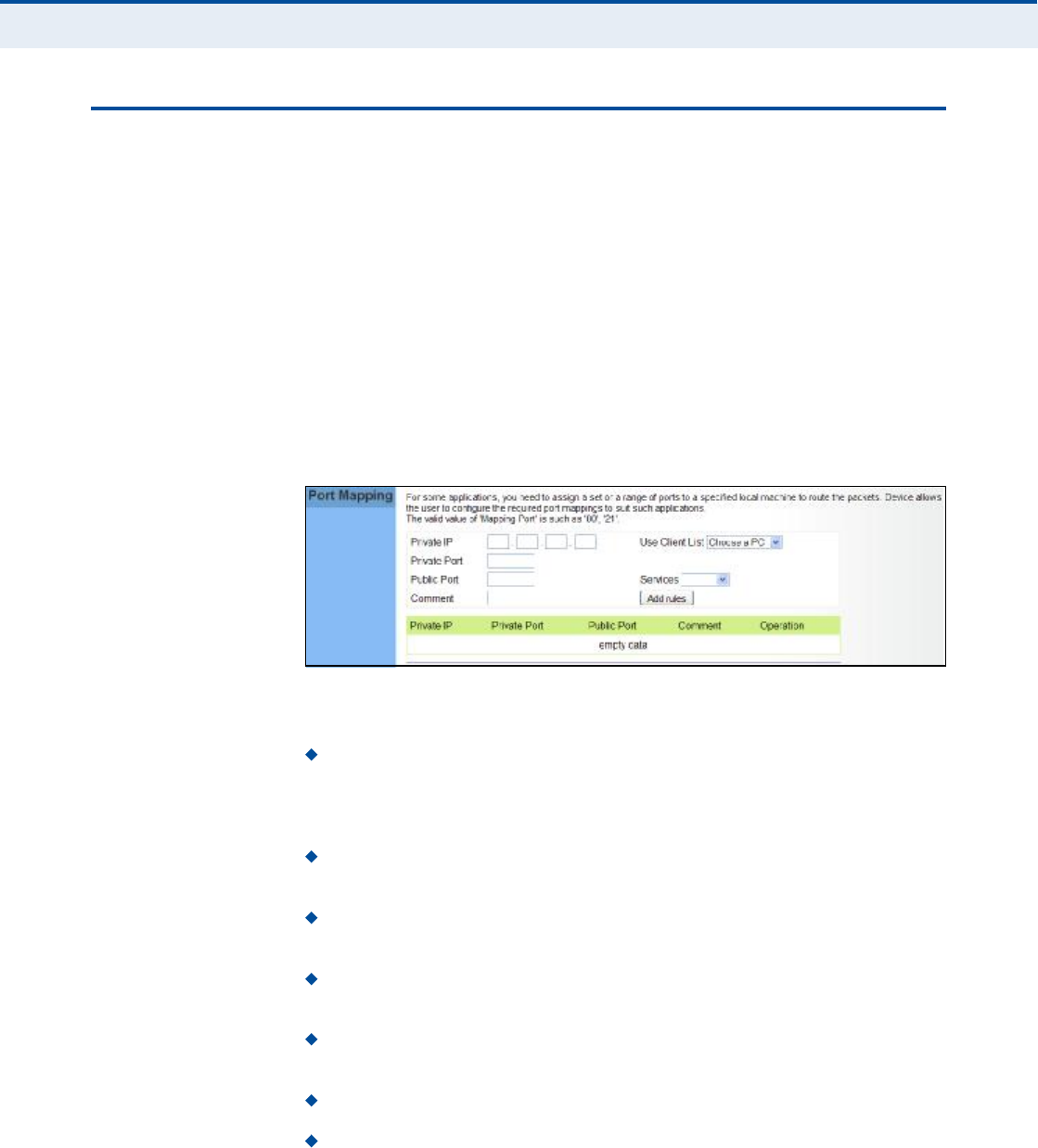
Ý
ØßÐÌÛÎ
é
| NAT Configuration
Port Mapping
49
ÐÑÎÌ ÓßÐÐ×ÒÙ
Using the NAT Port Mapping feature, remote users can access different
servers on your local network using your single public IP address.
Remote users accessing services such as web or FTP at your local site
thorugh your public IP address, are redirected (mapped) to other local
server IP addresses and TCP/UDP port numbers. For example, if you set
Type/Public Port to TCP/80 (HTTP or web) and the Private IP/Port to
192.168.7.9/80, then all HTTP requests from outside users forwarded to
192.168.7.9 on port 80. Therefore, by just using your external IP address
provided by your ISP, Internet users can access the services they need at
the local addresses to which you redirect them.
The more common TCP service port numbers include: HTTP: 80, FTP: 21,
Telnet: 23, and SSH: 22.
Figure 33: Port Mapping
The following parameters are displayed on this page:
Private IP The IP address of the server on the local Ethernet
network. The specified address must be in the same subnet as the
RG300 and its DHCP server address pool. Alternatively, the IP address
can be set by selecting a PC from the DHCP client list.
Use Client List Allows the Private IP to be selected from the DHCP
client list.
Private Port Specifies the TCP/UDP port number used on the local
server for the service. (Range: 1-65535)
Public Port Specifies the public TCP/UDP port used for the service on
the WAN interface. (Range: 1-65535)
Services Specifies port numbers for some of the more common
services. (Options: FTP, SSH, Telnet, SMTP, HTTP, HTTPS)
Comment A text comment for the forwarding rule.
Add Rules Adds the defined rule to the port forwarding table. Use
the Delete button next to a rule to remove it from the table.
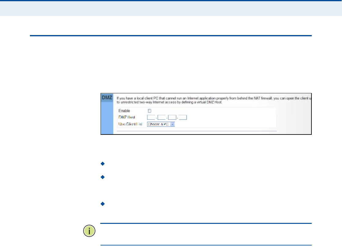
Ý
ØßÐÌÛÎ
é
| NAT Configuration
DMZ
50
ÜÓÆ
If you have a client PC that cannot run an Internet application properly
from behind the NAT firewall, you can open the client up to unrestricted
two-way internet access by defining a virtual-DMZ (virtual-demilitarized-
zone) host.
Figure 34: DMZ Settings
The following parameters are displayed on this page:
Enable Enables the feature.
DMZ Host Specifies the IP address of the virtual DMZ host.
Alternatively, the host IP can be set by selecting a PC from the DHCP
client list.
Use Client List Allows the host IP to be selected from the DHCP
client list.
Ò
ÑÌÛ
æ
Adding a host to the DMZ may expose your local network to a
variety of security risks, so only use this option as a last resort.
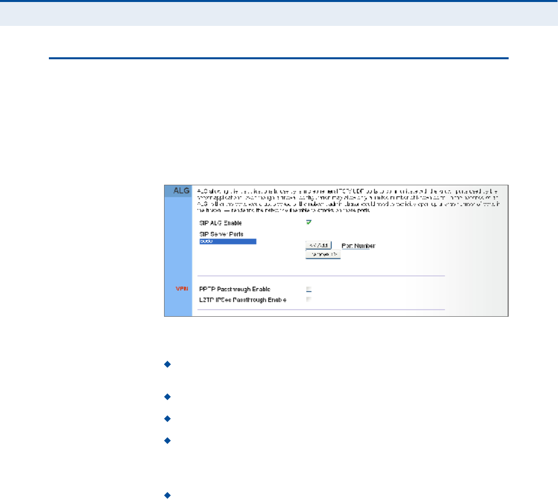
Ý
ØßÐÌÛÎ
é
| NAT Configuration
ALG
51
ßÔÙ
The RG300 supports the passthrough of three of the most commonly used
VPN protocols; PPTP, L2TP, and IPsec, as well as VoIP SIP traffic. The VPN
protocols allow remote users to establish a secure connection to their
corporate network. If your service provider supports VPNs, then these
protocols can be used to create an authenticated and encrypted tunnel for
passing secure data over the Internet (that is, a traditionally shared data
network).
Figure 35: ALG Settings
The following items are displayed on this page:
SIP ALG Enable $ Enables the passthrough of VoIP SIP traffic on the
configured server port numbers.
SIP Server Ports $ Lists the SIP server ports used for VoIP traffic.
Port Number $ Adds a new SIP Server port number.
PPTP Passthrough ! PPTP (Point-to-Point Tunneling Protocol)
provides a secure tunnel for remote client access to a PPTP security
gateway. PPTP includes provisions for call origination and flow control
required by ISPs.
L2TP IPsec Passthrough ! L2TP (Layer 2 Tunneling Protocol)
merges the best features of PPTP and the Layer 2 Forwarding (L2F)
protocol. Like PPTP, L2TP requires that the ISP!s routers support the
protocol. IPsec (Internet Protocol Security) encrypts and authenticates
entire IP packets and encapsulates them into new IP packets for secure
communications between networks.

52
èÚ×ÎÛÉßÔÔ ÝÑÒÚ×ÙËÎßÌ×ÑÒ
The information in this chapter covers the configuration options for the
RG300!s firewall functions.
The Firewall configuration pages include the following options:
"Firewall Settings# on page53
"Client Filtering# on page54
"Port Filtering# on page55
"MAC Filtering# on page56
"URL Filtering# on page57
"Host Filtering# on page58

Ý
ØßÐÌÛÎ
è
| Firewall Configuration
Firewall Settings
53
Ú×ÎÛÉßÔÔ ÍÛÌÌ×ÒÙÍ
The RG300 provides extensive firewall protection by restricting connection
parameters to limit the risk of intrusion and defending against a wide array
of common hacker attacks. You can also block access to the Internet from
clients on the local network based on IP addresses and TCP/UDP port
numbers, or specific MAC addresses.
Figure 36: Firewall Settings
The following parameters are displayed on this page:
Enable Enables all firewall features.
Disallow PING from WAN side Prevents pings on the unit!s WiMAX
interface from being routed to the network.
Allow Access WebUI from WAN Allows a user to be able to log into
the Gateway web interface from a remote location.
HTTP Log Enables LAN-to-WAN and WAN-to-LAN HTTP traffic to be
logged. The logged information can be viewed on the system log page.

Ý
ØßÐÌÛÎ
è
| Firewall Configuration
Client Filtering
54
ÝÔ×ÛÒÌ Ú×ÔÌÛÎ×ÒÙ
You can block access to the Internet from clients on the local network by
specifying IP addresses and TCP/UDP port numbers. You can configure up
to five IP filters on the unit.
Figure 37: Client Filtering Settings
The following parameters are displayed on this page:
Target IP Specifies an IP address or range on the local network to
filter.
Destination Port Range Specifies a TCP/UDP port number range to
filter. (Range: 1-65535 or Any)
Protocol Specifies the the port type. (Options: TCP, UDP, Any)
Add Adds a new IP address to the filter table.
Remove Removes an IP address from the filter table.

Ý
ØßÐÌÛÎ
è
| Firewall Configuration
Port Filtering
55
ÐÑÎÌ Ú×ÔÌÛÎ×ÒÙ
Port filtering restricts connections to limit the risk of intrusion and can
defend against a wide array of common hacker attacks. The port filtering
feature allows the Gateway to block traffic for a specified schedule based
on TCP/UDP ports.
Figure 38: Port Filtering
The following items are displayed on this page:
Available Services $ The TCP/UDP services allowed access to the
Gateway. All TCP/UDP ports are open unless specified as blocked. Some
common protocols are pre-defined and can be selected to "Add# to the
Blocked Services. Select "Custom Port# to define other TCP/UDP port
ranges to block.
Operation $ Adds, removes, or clears all blocked services.
Blocked Services $ Lists the TCP/UDP ports that are blocked
Type $ Specifies the port type, TCP, UDP, or TCP/UDP.
Port Number $ Specifies a custom-defined range of TCP/UDP ports to
block.
Schedule to Block $ Configures the days of the week and times to
block the defined traffic.

Ý
ØßÐÌÛÎ
è
| Firewall Configuration
MAC Filtering
56
ÓßÝ Ú×ÔÌÛÎ×ÒÙ
You can block access to the Internet from clients on the local network
based on MAC addresses. You can configure up to 20 MAC address filters
on the unit.
Figure 39: MAC Filtering
The following parameters are displayed on this page:
MAC Address Specifies a local PC MAC address.
Use Client List Selects a local PC MAC address from the Gateway!s
DHCP client list table.
Add Adds a new MAC address to the filter table.
Remove Removes a MAC address from the filter table.

Ý
ØßÐÌÛÎ
è
| Firewall Configuration
URL Filtering
57
ËÎÔ Ú×ÔÌÛÎ×ÒÙ
The RG300 provides a method for blocking Internet access based on
Uniform Resource Locator (URL) keywords. By filtering URLs accessed from
the network, users can be prevented from reaching prohibited online
content.
Figure 40: URL Filtering
The following items are displayed on this page:
String $ Specifies text keyword contained in URLs that will be filtered.
(Maximum 256 characters; invalid characters [% " & ' # \].)
Add $ Adds a keyword string to the URL filter.
Remove Removes an entry from the filter table.

Ý
ØßÐÌÛÎ
è
| Firewall Configuration
Host Filtering
58
ØÑÍÌ Ú×ÔÌÛÎ×ÒÙ
The RG300 provides a method for blocking Internet access based on web
domains. A domain name is the name of a particular web site. For
example, www.fungames.com.
Figure 41: Host Filtering
The following items are displayed on this page:
Host String $ Displays current Host filter. (Maximum 256 characters;
invalid characters [% " & ' # \].)
Add $ Enters a domain name keyword for a host filtering. For
example, myhost.example.com.
Remove $ Removes an entry from the filter table.

59
çÎÑËÌ×ÒÙ ÝÑÒÚ×ÙËÎßÌ×ÑÒ
The information in this chapter covers the configuration options for the
RG300!s Routing functions.
The Routing configuration pages include the following options:
"Routing Table# on page60
"Static Route# on page61
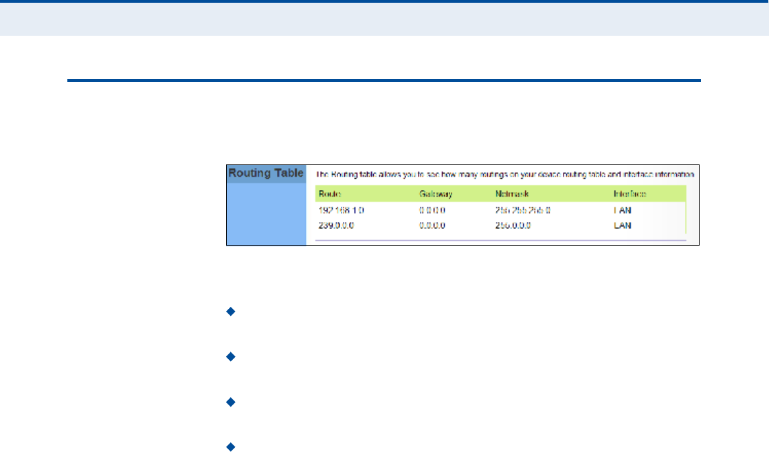
Ý
ØßÐÌÛÎ
ç
| Routing Configuration
Routing Table
60
ÎÑËÌ×ÒÙ ÌßÞÔÛ
The
Routing Table displays the list of static routes on the unit.
Figure 42: Routing Table
The following parameters are displayed in this section on this page:
Route The IP address that identifies the IP subnet of the remote
network.
Gateway The IP address of the router within the local IP subnet that
forwards traffic to the remote IP subnet.
Netmask The mask that identifies the IP subnet of the remote
network.
Interface Indicates the local network interface on the unit.

Ý
ØßÐÌÛÎ
ç
| Routing Configuration
Static Route
61
ÍÌßÌ×Ý ÎÑËÌÛ
Static routes allow a manual method to set up routing between specific
destination networks, subnetworks, or hosts. Static routes may be required
to force the use of a specific route to a subnet. Static routes do not
automatically change in response to changes in network topology, so only
configure a small number of stable routes to ensure network accessibility.
Figure 43: Static Route
The following items are displayed on this page:
Enable $ Enables the configured routes in the Static Route table.
Destination $ A destination network or specific host to which packets
can be routed.
Netmask $ Network mask for the associated IP subnet. This mask
identifies the host address bits used for routing to specific subnets.
Gateway $ The IP address of the router at the next hop to which
matching frames are forwarded.
Add $ Adds a new route to the table.

62
ïð ËÐÒÐ ÝÑÒÚ×ÙËÎßÌ×ÑÒ
The information in this chapter covers the configuration options for the
RG300!s Universal Plug and Play Forum (UPnP) feature.
The UPnP configuration pages include the following options:
"UPnP# on page63

Ý
ØßÐÌÛÎ
ïð
| UPnP Configuration
UPnP
63
ËÐÒÐ
UPnP (Universal Plug and Play Forum) provides inter-connectivity between
devices supported by the same standard.
Figure 44: UPnP Setting
The following parameters are displayed in this section on this page:
UPnP Enables UpnP support on the unit.
64
ïï ÊÑ×Ð ÍÛÌÌ×ÒÙÍ
Voice over Internet Protocol (VoIP) technology is a way of using the
Internet to make phone calls. Phone calls can be tranmitted over the
Internet by encoding a voice call into data packets at one end and then
decoding it back into voice calls at the other end. This encoding and
decoding is from a analog signal (your voice) into a digital signal (data
packets) and then back into an analog signal.
The RG300 uses Session Initiation Protocol (SIP) as the control
mechanism that sets up, initiates, and terminates calls between a caller
and a called party. The SIP messaging makes use of "Proxy,# "Redirect,#
and "Registration# servers to process call requests and find the location of
called parties across the Internet. When SIP has set up a call between two
parties, the actual voice communication is a direct peer-to-peer connection
using the standard Real-Time Protocol (RTP), which streams the encoded
voice data across the network.
You can make VoIP calls by connecting a regular phone to one of the
RG300!s RJ-11 Phone ports. The RG300 allows up to two RJ-11 Phone ports
to be configured separately with different settings.
The VoIP configuration pages include the following options:
"SIP Account# on page65
"SIP Settings# on page66
"Speed Dial# on page67
"Dial Plan# on page68
"Call Feature# on page70
"Phone Settings# on page72
"Codecs# on page73

Ý
ØßÐÌÛÎ
ïï
| VoIP Settings
SIP Account
65
Í×Ð ßÝÝÑËÒÌ
From the VoIP SIP Account page, you can view the SIP account numbers
that have been provided by the service operator.
Figure 45: SIP Account Settings
The following parameters are displayed on this page:
Proxy Enable ! When enabled, forwards SIP messages to a SIP proxy
instead of a SIP domain.
Enable ! Enables the VoIP ports on the Gateway.
Telephone Number ! The phone number that is assigned to this
phone line.
The same with Telephone Number ! Uses the specified Telephone
Number as the Outgoing Display Name.
Outgoing Display Name ! The name that is displayed to the other
party during a call.
The same with WiMAX Username and Password ! Uses the
WiMAX user name and password as the SIP user name and password.
SIP Username ! Enter your SIP user name.
SIP Password ! Enter your SIP password.
Confirm Password ! Re-enter your SIP password.

Ý
ØßÐÌÛÎ
ïï
| VoIP Settings
SIP Settings
66
SIP Registrar/Domain Name $ Enter the IP address or server
domain name of the SIP server.
SIP Registrar Port ! Enter the port associated with SIP server traffic.
SIP Proxy Address/Domain Name ! Address of the VoIP service
provider SIP proxy server.
SIP Proxy Port ! The TCP port number used by the VoIP service
provider!s SIP proxy server.
Reg Keep Alive I/O Period $ The maximum time (in seconds)
between keep-alive messages sent to the SIP register server.
Í×Ð ÍÛÌÌ×ÒÙÍ
The SIP Setting page allows you to configure RTP, DTMF, and FAX settings.
Figure 46: SIP Settings
The following items are displayed on this page:
RTP Port ! The Real-time Transport Protocol (RTP) and Real-time
Control Protocol (RTCP) do not use specified port numbers. You can
specify a port base that the RTP and RTCP traffic can use.
DTMF Key Pad ! Enables the sending of dual-tone multi-frequency
(touch tone) phone signals over the VoIP connection. There are two
methods to choose from:
In-band ! The DTMF signals are sent over the RTP voice stream.
In the case when low-bandwidth codecs are used, the DTMF signals
may be distorted.
RFC2833 ! Uses the RFC 2833 method to relay the DTMF signals
over the RTP voice stream without any distortion.

Ý
ØßÐÌÛÎ
ïï
| VoIP Settings
Speed Dial
67
FAX ! Selects the method to use when sending fax messages over the
VoIP network from a fax machine connected to one of the RJ-11 Phone
ports on the Gateway.
FAX T.38 ! The SIP protocol sets up the VoIP call, then the T.38
Fax Relay protocol sends the fax data over the network.
FAX Pass-Through ! Enables voice calls and faxes to be sent
from the Phone port connection. For this option, fax signals are sent
over the VoIP network using the voice codec, just as if it were a
voice call.
Session Timer Enable ! Enables a limit on the duration of VoIP calls.
Session Timer Interval $ Sets the maximum time limit for VoIP calls.
ÍÐÛÛÜ Ü×ßÔ
The Speed Dial page allows you to configure up to eight VoIP numbers that
are immediately dialed when a user enters the Speed Dial Key sequence
(as defined on the Dial Plan page) followed by a speed dial number.
Figure 47: Speed Dial

Ý
ØßÐÌÛÎ
ïï
| VoIP Settings
Dial Plan
68
Ü×ßÔ ÐÔßÒ
Dial-plan strings specify key sequences used for specific calling features
(Transfer, New Call, 3-way conference), as well as defining call restriction
filters.
A dial plan can filter the number and pattern of digits that a user dials to
reach a particular telephone number. Access codes, area codes, specialized
codes, and combinations of the number of digits dialed can all be part of a
dial plan. This enables a user to predefine dialling sequences that are
permitted.
The dial-plan string consists of a single digit rule. A typical example of a
dial-plan string is: [0123]xxxxxx.t
Five standard dial plans are defined; Call Transfer Key, New Call Key, Set
Speed Dial Key, Speed Dial Key, and 3-way Conference. Up to 10 other dial
plans can be defined by the user.
Figure 48: Dial Plan Settings
The function of elements allowed in a dial plan are described in the table
below:
Table 5: Dial Plan Elements
Element Example Description
xxxxxRepresents a digit of any value ( 0 to 9) that can be dialed on a
phone. This example has a rule with four digits of any number.
.xx. Indicates zero or more occurrences of the previous symbol. The
example acts like a wildcard, meaning any dialed phone number
of two or more digits is allowed.
0-901xxIndicates dialed digits that must be matched. This example only
allows four-digit numbers starting "01.#

Ý
ØßÐÌÛÎ
ïï
| VoIP Settings
Dial Plan
69
When a user dials a series of digits, the dial-plan rule is tested for a
possible match. If a match is made, the dialed sequence is transmitted. If
no match is made, the dialed number is blocked and the user will hear an
error tone.
A dial-plan string cannot include spaces between elements. Dialed
sequences that are longer than specified in a dial-plan rule are truncated
after the number of specified digits. For example, if the dial-plan rule is
"011x# and "0115678# is dialed, only the digit sequence "0115# is
transmitted.
[ ][125-8] Limits a dialed digit to specified values or a range of values. The
example specifies that only digits 1, 2, 5, 6, 7, and 8 are
permitted.
txx.tThe timeout indicator that can placed after dialed digits or at the
end of the dial-plan string.
Table 5: Dial Plan Elements
Element Example Description
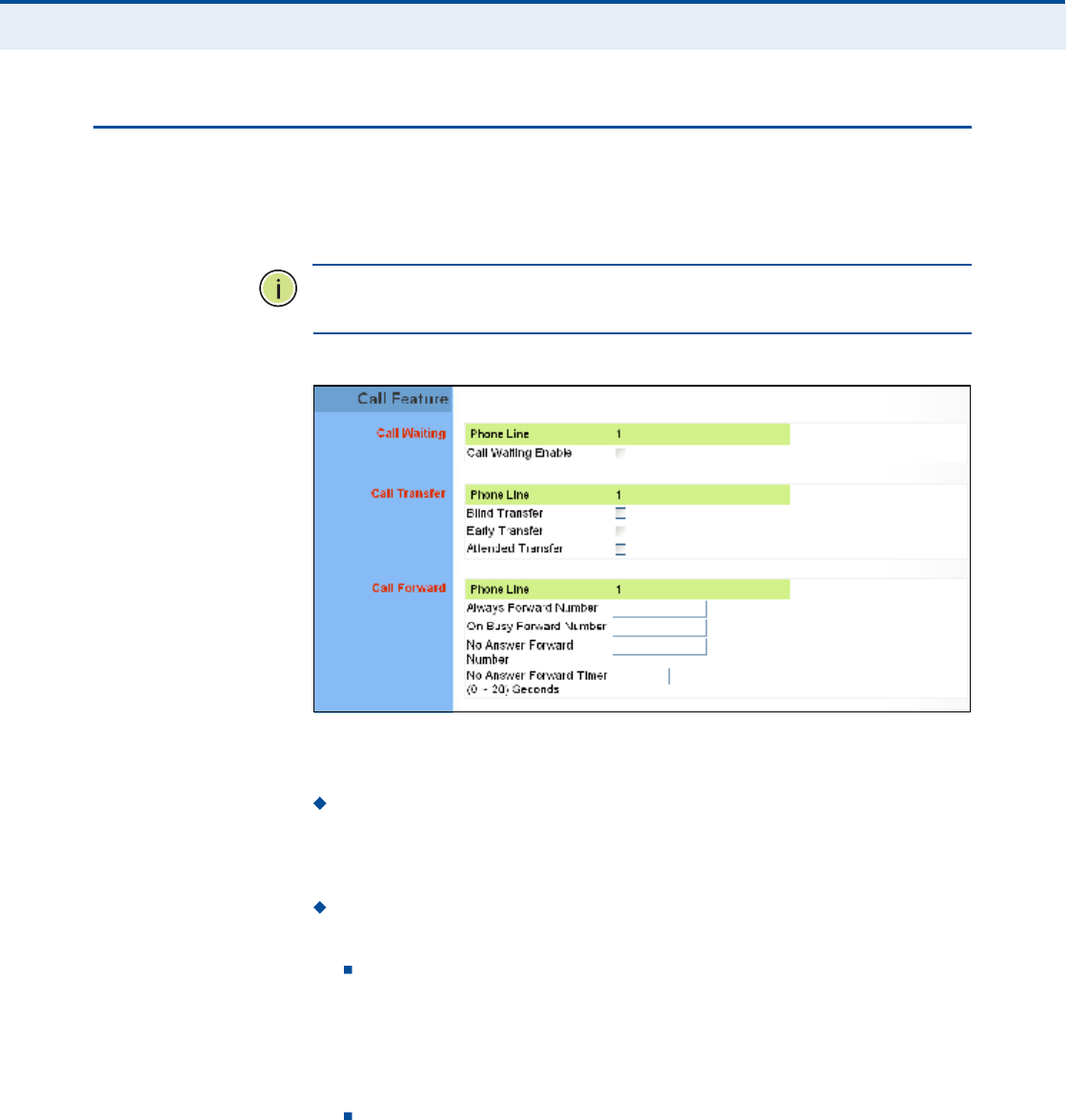
Ý
ØßÐÌÛÎ
ïï
| VoIP Settings
Call Feature
70
ÝßÔÔ ÚÛßÌËÎÛ
The RG300 allows you to configure several call features, such as call
waiting and call-forwarding. Other call features can be implemented by
pressing specific phone buttons or entering dial patterns.
Ò
ÑÌÛ
æ
Some call features may be dependent on support at the SIP server.
Check with the SIP service provider.
Figure 49: Call Features
The following items are displayed on this page:
Call Waiting $ Enables a call waiting alert. If during a call there is
another incoming call, an alert tone is heard. You can place the active
call on hold (press the "Flash# or "Flash Hook# button on the phone)
and switch to the incoming call.
Call Transfer ! Transfers any received call to another number you
specify.
Blind Transfer $ During a call press the "Flash# button, which
puts the caller on hold, then enter the transfer key sequence (as
defined on the Dial Plan page; default "*##). You can then dial the
transfer number. The call is transfered immediately and you can
hang up. The transfered call shows the caller ID of the original
calling party and not your caller ID.
Early Transfer $ During a call press the "Flash# button, which puts
the caller on hold, then enter the new call key sequence (as defined
on the Dial Plan page; default "**#). You can then dial the transfer
number. When you hear the transfer number ringtone, enter the
transfer key sequence (as defined on the Dial Plan page; default
"*##) and then hang up. The transfered call initially shows your

Ý
ØßÐÌÛÎ
ïï
| VoIP Settings
Call Feature
71
caller ID when the transferee phone is ringing, but then shows the
original calling party ID as soon as you hang up.
Attended Transfer $ During a call press the "Flash# button, which
puts the caller on hold, then enter the new call key sequence (as
defined on the Dial Plan page; default "**#). You can then dial the
transfer number and talk to the transferee. After speaking to the
transferee, enter the transfer key sequence (as defined on the Dial
Plan page; default "*##) and then hang up to transfer the call. The
transfered call shows your caller ID and not the caller ID of the
original calling party.
Call Forward ! Configures settings that control various call
forwarding features.
Always Forward Number $ Forwards an incoming call to another
number.
On Busy Forward Number $ When Call Waiting is disabled,
specifies another phone number to which incoming calls are
forwarded when the phone is busy.
No Answer Forward Number $ Another phone number to which
incoming calls are forwarded when there is no answer.
No Answer Forward Timer $ The time a call waits for an answer
before being forwarded to the No Answer Forward Phone Number.
(Must be less than or equal to the value of Answer Timeout; Range:
0~20 seconds)

Ý
ØßÐÌÛÎ
ïï
| VoIP Settings
Phone Settings
72
ÐØÑÒÛ ÍÛÌÌ×ÒÙÍ
The Phone Settings page allows you to configure control features that
affect a phone connected to a VoIP port.
Figure 50: Phone Settings
The following items are displayed on this page:
Caller ID Block ! Check this box to enable a block on the displayed
ID of incoming calls.
Echo Cancellation $ Enables a time delay for voice echo cancellation.
A voice echo can be created on some two-wire phone loops, which
becomes increasingly louder and annoying when there is a long delay.
If voice echo is a problem during a call, you can enable this parameter
to try and reduce or remove it.
Voice Activation Detection $ Enables the detection of periods of
silence in the audio stream so that they are not transmitted over the
network.
Comfortable Noise Generation $ Creates artificial noise for the
listener during detected silent intervals in the audio stream.
Answer Timeout $ The time after which a no answer message is sent
to the caller. (Range: 0-60 seconds; Setting of zero disables the
timeout)
Dial Tone Timeout $ The length of time a dial tone is heard on a
connected phone. (Range: 0-60 seconds; Setting of zero disables the
timeout)
Inter Digit Timeout $ The maximum time delay allowed between
each dialed digit. When the time is exceeded, a call is made using the
dialed digits. (Range:0-10seconds; Setting of zero disables the
timeout)
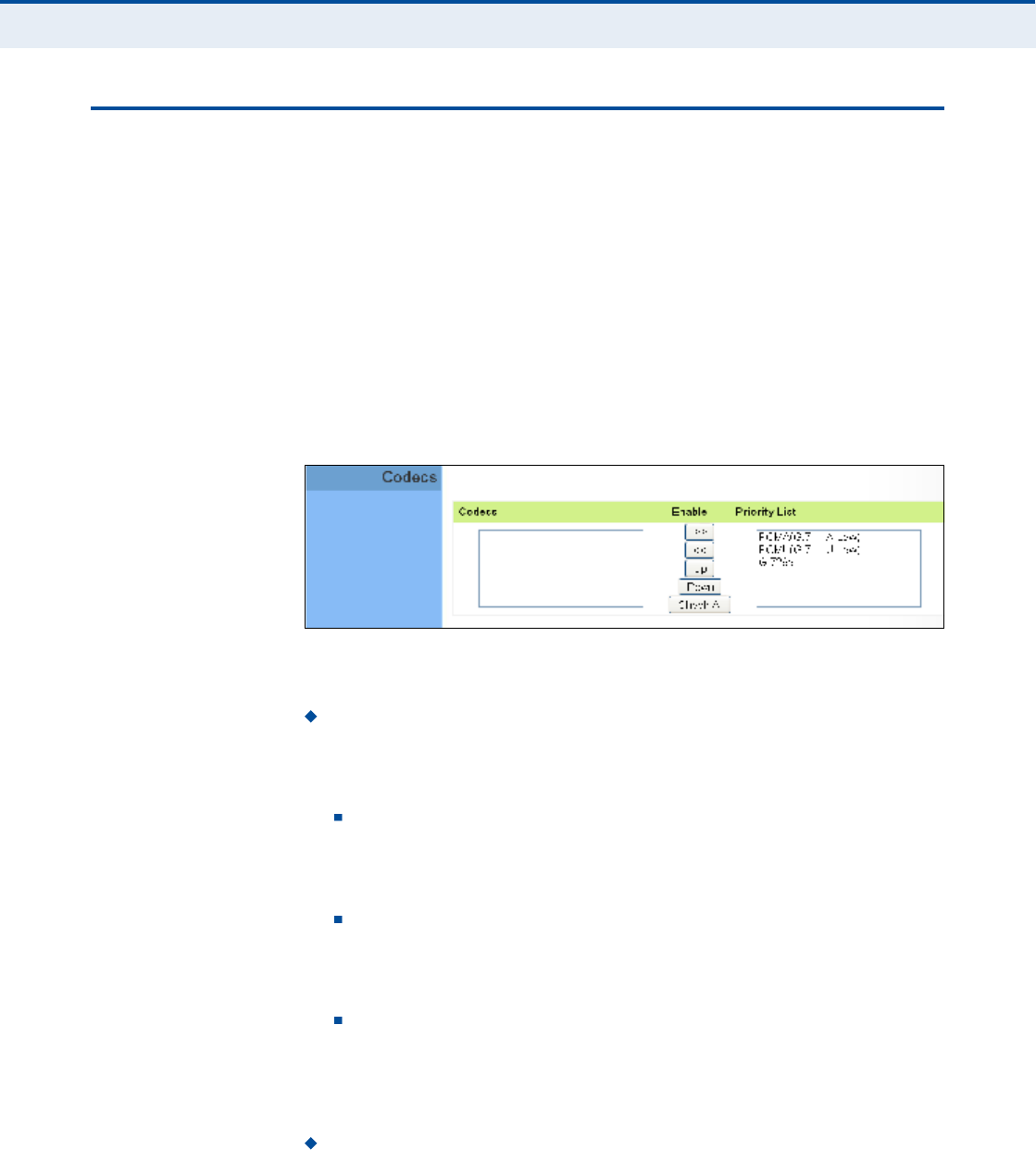
Ý
ØßÐÌÛÎ
ïï
| VoIP Settings
Codecs
73
ÝÑÜÛÝÍ
A codec (coder/decoder) is the way a voice analog signal is converted into
a digital bitstream to send over the network, and how it is converted back
into an analog signal at the receiving end. Codecs differ in the type of data
compression that is used to save network bandwidth and in the time delay
caused in the signal. This results in different voice quality experienced by
the user.
The voice codecs in common use today have been standardized by the
International Telecommunication Union Telecommunication Standardization
Sector (ITU-T) and are identified by a standard number, such as G.711.
The same codec must be supported at each end of a VoIP call to be able to
encode and decode the signal. Since devices in other networks may want
to use different codecs, the RG300 supports several common standards.
Figure 51: VoIP Codecs
The following items are displayed on this page:
Codecs $ Lists the codecs supported by the Gateway. You can enable
specific codecs to use, or enable all. Alternatively, you may want to
disable certain codecs, such as high-bandwidth codecs, to preserve
network bandwidth.
PCMA (G.711 ALaw) $ The ITU-T G.711 with A-law standard
codec that uses Pulse Code Modulation (PCM) to produce a 64 Kbps
high-quality voice data stream. This standard is used in Europe and
most other countries around the world.
PCMU (G.711 ULaw) $ The ITU-T G.711 with mu-law standard
codec that uses Pulse Code Modulation (PCM) to produce a 64 Kbps
high-quality voice data stream. This standard is used in North
America and Japan.
G.729a $ The ITU-T G.729ab standard codec that uses Conjugate
Structure Algebraic-Code Excited Linear Prediction (CS-ACELP) with
silence suppression to produce a low-bandwidth data stream of 8
Kbps. Note that DTMF and fax tones do not transport reliably with
this codec, it is better to use G.711 for these signals.
Priority List $ The Gateway automatically negotiates the codec to use
for each called party. You can specify a priority for the codecs that you
prefer to use. Select a codec in the list, then use the UP and DOWN

Ý
ØßÐÌÛÎ
ïï
| VoIP Settings
Codecs
74
buttons to set the priority. The Gateway attempts to use the codec
highest in the list before trying the next lower one.

75
ïî É×óÚ× ÍÛÌÌ×ÒÙÍ
The RG300 includes an IEEE 802.11n radio interface for local Wi-Fi
communications. The Wi-Fi set up pages include configuration options for
the radio signal characteristics and Wi-Fi security.
The Wi-Fi configuration pages include the following options:
"Basic Wireless Settings# on page76
"Advanced Wireless Settings# on page78
"Wireless Security# on page79
"ACL Settings# on page83
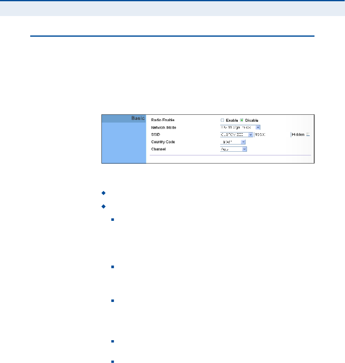
Ý
ØßÐÌÛÎ
ïî
| Wi-Fi Settings
Basic Wireless Settings
76
ÞßÍ×Ý É×ÎÛÔÛÍÍ ÍÛÌÌ×ÒÙÍ
From the WiFi menu, click on Basic to configure basic settings for the unit!s
Wi-Fi radio interface. The unit!s radio can operate in six modes,
IEEE802.11b/g mixed, 802.11b only, 802.11g only, 802.11n only,
802.11g/n mixed, and 802.11b/g/n mixed.
Note that IEEE 802.11g is backward compatible with 802.11b, and 802.11n
is backward compatible with 802.11b/g at slower data transmit rates.
Figure 52: Wireless Settings
The following items are displayed on this page:
Radio Enable $ Enables or disables the radio.
Network Mode $ Defines the radio operating mode.
11b/g mixed: Both 802.11b and 802.11g clients can communicate
with the Wi-Fi radio (up to 108 Mbps), but data transmission rates
may be slowed to compensate for 802.11b clients. Any 802.11n
clients will also be able to communicate with the Wi-Fi radio, but
they will be limited to 802.11g protocols and data transmission
rates.
11b only: All 802.11b, 802.11g, and 802.11n clients will be able to
communicate with the Wi-Fi radio, but the 802.11g and 802.11n
clients will be limited to 802.11b protocols and data transmission
rates (up to 11 Mbps).
11g only: Both 802.11g and 802.11n clients will be able to
communicate with the Wi-Fi radio, but the 802.11n clients will be
limited to 802.11g protocols and data transmission rates (up to
54Mbps). Any 802.11b clients will not be able to communicate with
the Wi-Fi radio.
11n only: Only 802.11n clients will be able to communicate with
the Wi-Fi radio (up to 150 Mbps).
11g/n mixed: Both 802.11g and 802.11n clients can communicate
with the Wi-Fi radio (up to 150 Mbps), but data transmission rates
may be slowed to compensate for 802.11g clients.
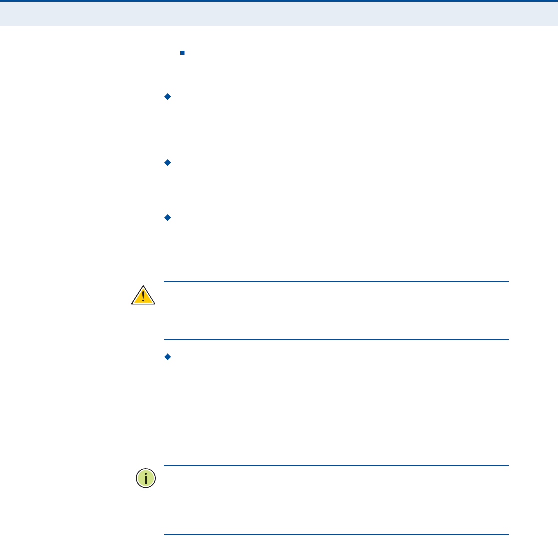
Ý
ØßÐÌÛÎ
ïî
| Wi-Fi Settings
Basic Wireless Settings
77
11b/g/n Mixed: All 802.11b/g/n clients can communicate with the
Wi-Fi radio (up to 150 Mbps), but data transmission rates may be
slowed to compensate for 802.11b/g clients.
SSID $ The name of the wireless network service provided by the Wi-
Fi radio. Clients that want to connect to the network must set their
SSID to the same as that of the Wi-Fi radio. Select "CUSTOMIZED# to
set a specific text string, or select "MAC# to use the device MAC address
as the SSID. (Range: 1-32 characters)
Hidden $ By default, the Wi-Fi radio always broadcasts the SSID in its
beacon signal. Disabling the SSID broadcast increases security of the
network because wireless clients need to already know the SSID before
attempting to connect.
Country Code $ The country code restricts operation of the Wi-Fi
radio to the channels and transmit power levels permitted for Wi-Fi
networks in the specified region. You must set the correct Country Code
to be sure the radio conforms to local regulations. (Options: United
States, Japan, France, Taiwan, Ireland)
Ý
ßËÌ×ÑÒ
æ
You must set the country code to the country of operation.
Setting the country code restricts operation of the access point to the radio
channels and transmit power levels permitted for wireless networks in the
specified country.
Channel $ The radio channel that the Wi-Fi radio uses to communicate
with wireless clients. When multiple access points are deployed in the
same area, set the channel on neighboring access points at least five
channels apart to avoid interference with each other. For example, you
can deploy up to three access points in the same area using channels 1,
6, 11. Note that wireless clients automatically set the channel to the
same as that used by the Wi-Fi radio to which it is linked. Selecting
Auto Select enables the Wi-Fi radio to automatically select an
unoccupied radio channel.
Ò
ÑÌÛ
æ
If you experience poor performance, you may be encountering
interference from another wireless device. Try changing the channel, as
this may eliminate interference and increase performance. Channels 1, 6,
and 11, as the three non-overlapping channels in the 2.4 GHz band, are
preferred.
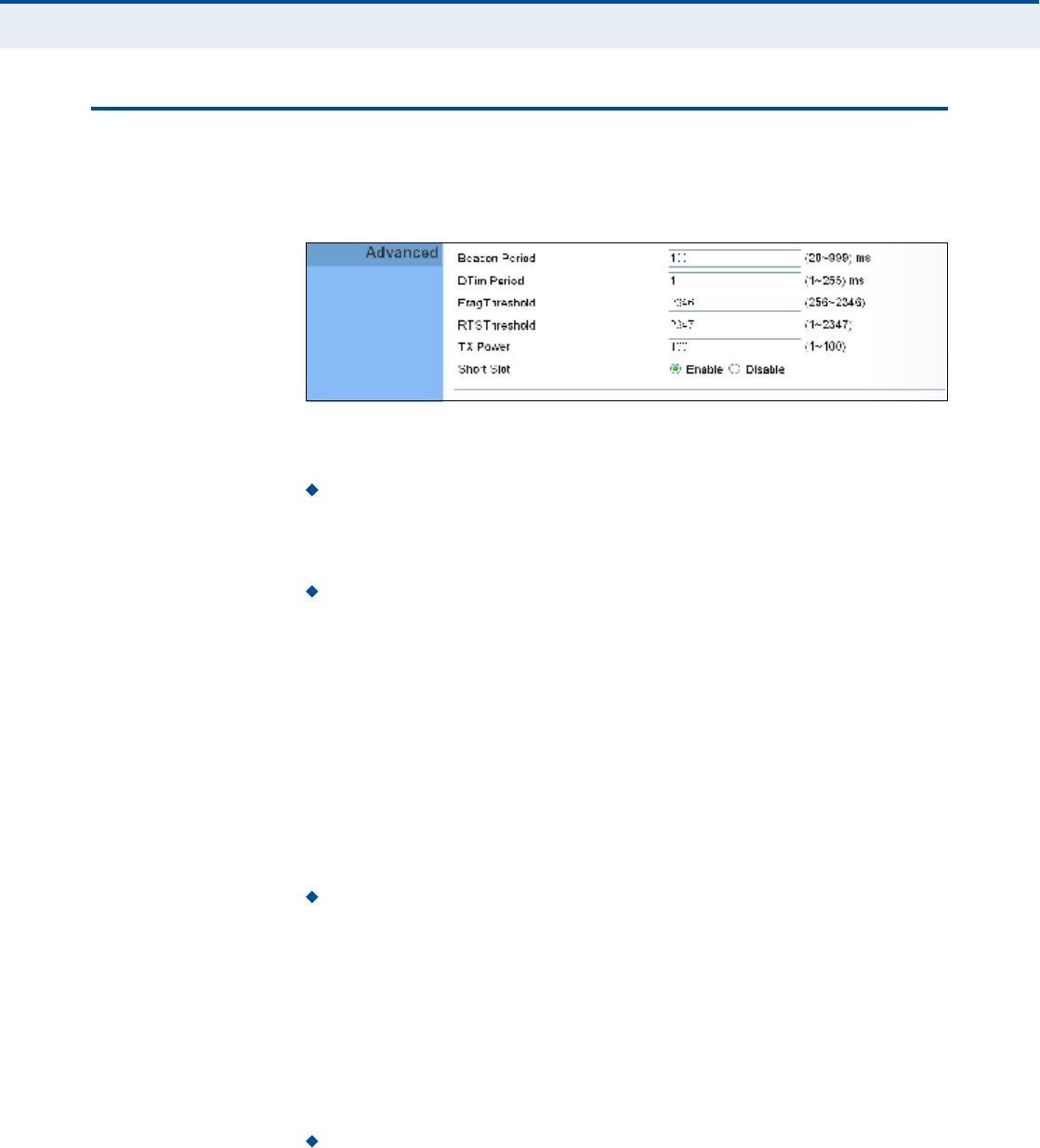
Ý
ØßÐÌÛÎ
ïî
| Wi-Fi Settings
Advanced Wireless Settings
78
ßÜÊßÒÝÛÜ É×ÎÛÔÛÍÍ ÍÛÌÌ×ÒÙÍ
The Advanced Settings page includes additional parameters concerning the
wireless network and Wi-Fi Multimedia settings.
Figure 53: Advanced Wireless Settings
The following items are displayed on this page:
Beacon Period $ The rate at which beacon signals are transmitted
from the access point. The beacon signals allow wireless clients to
maintain contact with the access point. They may also carry power-
management information. (Range: 20-999 TUs)
DTIM Period $ The rate at which stations in sleep mode must wake
up to receive broadcast/multicast transmissions.
Known also as the Delivery Traffic Indication Map (DTIM) interval, it
indicates how often the MAC layer forwards broadcast/multicast traffic,
which is necessary to wake up stations that are using Power Save
mode. The value of one beacon indicates that the access point will save
all broadcast/multicast frames for the Basic Service Set (BSS) and
forward them after every beacon. Using smaller DTIM intervals delivers
broadcast/multicast frames in a more timely manner, causing stations
in Power Save mode to wake up more often and drain power faster.
Using higher DTIM values reduces the power used by stations in Power
Save mode, but delays the transmission of broadcast/multicast frames.
(Range: 1-255 beacons)
Frag Threshold Configures the minimum packet size that can be
fragmented when passing through the access point. Fragmentation of
the PDUs (Package Data Unit) can increase the reliability of
transmissions because it increases the probability of a successful
transmission due to smaller frame size. If there is significant
interference present, or collisions due to high network utilization, try
setting the fragment size to send smaller fragments. This will speed up
the retransmission of smaller frames. However, it is more efficient to
set the fragment size larger if very little or no interference is present
because it requires overhead to send multiple frames. (Range:256-
2346bytes)
RTS Threshold $ Sets the packet size threshold at which a Request to
Send (RTS) signal must be sent to a receiving station prior to the
sending station starting communications. The access point sends RTS

Ý
ØßÐÌÛÎ
ïî
| Wi-Fi Settings
Wireless Security
79
frames to a receiving station to negotiate the sending of a data frame.
After receiving an RTS frame, the station sends a CTS (clear to send)
frame to notify the sending station that it can start sending data.
If the RTS threshold is set to 0, the access point always sends RTS
signals. If set to 2347, the access point never sends RTS signals. If set
to any other value, and the packet size equals or exceeds the RTS
threshold, the RTS/CTS (Request to Send / Clear to Send) mechanism
will be enabled.
The access points contending for the medium may not be aware of each
other. The RTS/CTS mechanism can solve this "Hidden Node Problem.#
(Range: 1-2347 bytes)
TX Power Adjusts the power of the radio signals transmitted from
the unit. The higher the transmission power, the farther the
transmission range. Power selection is not just a trade off between
coverage area and maximum supported clients. You also have to
ensure that high-power signals do not interfere with the operation of
other radio devices in the service area. (Range: 1 - 100)
Short Slot $ Sets the basic unit of time the access point uses for
calculating waiting times before data is transmitted. A short slot time
(9microseconds) can increase data throughput on the access point, but
requires that all clients can support a short slot time (that is, 802.11g-
compliant clients must support a short slot time). A long slot time
(20microseconds) is required if the access point has to support
802.11b clients.
É×ÎÛÔÛÍÍ ÍÛÝËÎ×ÌÇ
The RG300!s Wi-Fi interface is configured by default as an "open system,#
which broadcasts a beacon signal including the configured SSID. Wireless
clients with a configured SSID of "ANY# can read the SSID from the
beacon, and automatically set their SSID to allow immediate connection to
the wireless network.
To implement wireless network security, you have to employ two main
functions:
Authentication It must be verified that clients attempting to connect
to the network are authorized users.
Traffic Encryption Data passing between the unit and clients must be
protected from interception and evesdropping.
The RG300!s Wi-Fi interface supports supports five different security
mechanisms that provide various levels of authentication and encryption
depending on the requirements of the network.
Click on "Wi-Fi,# followed by "Security#.
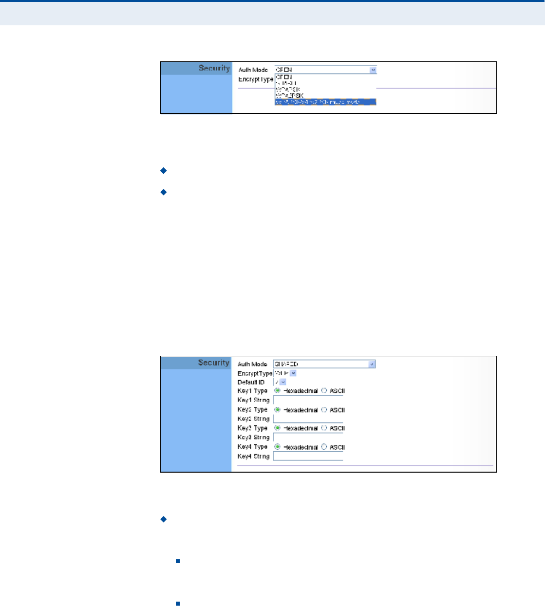
Ý
ØßÐÌÛÎ
ïî
| Wi-Fi Settings
Wireless Security
80
Figure 54: Security Mode Options
The supported security mechanisms and their configuration parameters are
described in the following sections:
OPEN, SHARED $ See "Wired Equivalent Privacy (WEP)# on page80.
WPAPSK, WPA2PSK, WPAPSK/WPA2PSK mixed mode $ See
"WPA Pre-Shared Key# on page81.
É×ÎÛÜ ÛÏË×ÊßÔÛÒÌ
ÐÎ×ÊßÝÇ øÉÛÐ÷
WEP provides a basic level of security, preventing unauthorized access to
the network, and encrypting data transmitted between wireless clients and
an access point. WEP uses static shared keys (fixed-length hexadecimal or
alphanumeric strings) that are manually distributed to all clients that want
to use the network.
When you select to use WEP, be sure to define at least one static WEP key
for user authentication or data encryption. Also, be sure that the WEP
shared keys are the same for each client in the wireless network.
Figure 55: Security Mode - WEP
The following items are displayed in this section on this page:
Auth Mode $ Configures the WEP security mode used by clients.
When using WEP, be sure to define at least one static WEP key for the
RG300 and all its clients.
OPEN $ Open-system authentication accepts any client attempting
to connect the RG300 without verifying its identity. In this mode the
default data encryption type is "WEP.#
SHARED $ The shared-key security uses a WEP key to
authenticate clients connecting to the network and for data
encryption.

Ý
ØßÐÌÛÎ
ïî
| Wi-Fi Settings
Wireless Security
81
Encrypt Type $ Selects WEP for data encryption (OPEN mode only).
Default ID $ Selects the WEP key number to use for authentication or
data encryption. If wireless clients have all four WEP keys configured to
the same values, you can change the encryption key to any of the
settings without having to update the client keys. (Range:1~4)
Key 1~4 Type $ Sets WEP key type as ASCII or hexadecimal.
Key 1~4 String $ Sets WEP key values. The user must first select
ASCII or hexadecimal keys. Each WEP key has an index number. Enter
key values that match the key type and length settings. Enter 5
alphanumeric characters or 10 hexadecimal digits for 64-bit keys, or
enter 13 alphanumeric characters or 26 hexadecimal digits for 128-bit
keys.
ÉÐß ÐÎÛóÍØßÎÛÜ
ÕÛÇ
Wi-Fi Protected Access (WPA) was introduced as an interim solution for the
vulnerability of WEP pending the adoption of a more robust wireless
security standard. WPA2 includes the complete wireless security standard,
but also offers backward compatibility with WPA. Both WPA and WPA2
provide an "enterprise# and "personal# mode of operation.
For small home or office networks, WPA and WPA2 provide a simple
"personal# operating mode that uses just a pre-shared key for network
access. The WPA Pre-Shared Key (WPA-PSK) mode uses a common
password phrase for user authentication that is manually entered on the
access point and all wireless clients. Data encryption keys are
automatically generated by the access point and distributed to all clients
connected to the network.
Figure 56: Security Mode - WPA-PSK
The following items are displayed in this section on this page:
Auth Mode $ Configures the WPA-PSK and WPA2-PSK security modes
used by clients. When using WPA-PSK or WPA2-PSK, be sure to define
the shared key for the RG300 and all its clients.
WPAPSK $ Clients using WPA with a Pre-shared Key are accepted
for authentication. The default data encryption type for WPA is TKIP.
WPA2PSK $ Clients using WPA2 with a Pre-shared Key are
accepted for authentication. The default data encryption type for
WPA is AES.

Ý
ØßÐÌÛÎ
ïî
| Wi-Fi Settings
Wireless Security
82
WPAPSK/WPA2PSK mixed mode $ Clients using WPA or WPA2
with a Pre-shared Key are accepted for authentication. The default
data encryption type is TKIP/AES.
EncryptType $ Selects the data encryption type to use. (Default is
determined by the Security Mode selected.)
TKIP $ Uses Temporal Key Integrity Protocol (TKIP) keys for
encryption. WPA specifies TKIP as the data encryption method to
replace WEP. TKIP avoids the problems of WEP static keys by
dynamically changing data encryption keys.
AES $ Uses Advanced Encryption Standard (AES) keys for
encryption. WPA2 uses AES Counter-Mode encryption with Cipher
Block Chaining Message Authentication Code (CBC-MAC) for
message integrity. The AES Counter-Mode/CBCMAC Protocol (AES-
CCMP) provides extremely robust data confidentiality using a 128-
bit key. Use of AES-CCMP encryption is specified as a standard
requirement for WPA2. Before implementing WPA2 in the network,
be sure client devices are upgraded to WPA2-compliant hardware.
TKIPAES $ Uses either TKIP or AES keys for encryption. WPA and
WPA2 mixed modes allow both WPA and WPA2 clients to associate
to a common SSID. In mixed mode, the unicast encryption type
(TKIP or AES) is negotiated for each client.
Pass Phrase $ The WPA Preshared Key can be input as an ASCII
string (an easy-to-remember form of letters and numbers that can
include spaces) or Hexadecimal format. (Range: 8~63 ASCII
characters, or exactly 64 Hexadecimal digits)

Ý
ØßÐÌÛÎ
ïî
| Wi-Fi Settings
ACL Settings
83
ßÝÔ ÍÛÌÌ×ÒÙÍ
Wireless clients can be authenticated for network access by checking their
MAC address against a local database configured on the RG300. You can
configure a list of up to 32 wireless client MAC addresses in the filter list to
allow network access.
Figure 57: ACL Settings
The following items are displayed on this page:
Enable $ Enables the ACL feature.
MAC Address $ Physical address of a client. Enter six pairs of
hexadecimal digits separated by colons; for example,
00:90:D1:12:AB:89.
Add $ Click to list a new specified MAC address in the MAC
Authentication Table.
Operation $ Click the Remove button to delete the specified MAC
address from the table.

84
ïí ÏÑÍ ÝÑÒÚ×ÙËÎßÌ×ÑÒ
The RG300 supports Quality of Service (QoS) settings that enable traffic
rate limits to be set for all or specific LAN clients.
The QoS configuration pages include the following options:
"QoS Settings# on page85

Ý
ØßÐÌÛÎ
ïí
| QoS Configuration
QoS Settings
85
ÏÑÍ ÍÛÌÌ×ÒÙÍ
From the QoS Settings page, you can set rate limits for outbound (WiMAX
uplink) traffic from all or specified clients.
Figure 58: QoS Settings
The following parameters are displayed on this page:
General $ Sets QoS parameters that apply to all LAN clients (except
those listed in the QoS Rules table):
Enable $ Enables the QoS settings on the Gateway.
Default Outbound Rate/Limit $ Sets a rate limit for the
outbound traffic from all clients not specified in the QoS Rules table.
The rate is specified in kilobytes per second (0 means unlimited).
Rules $ Specifies the QoS rate limits for specified client source IPs:
Source IP $ Specifies a source IP address on the local network.
The IP address can also be selected from the DHCP client list, as
indicated by "Use Client List.#
Use Client List Enables the Source IP to be selected from the
DHCP client list.
Outbound Rate/Limit $ Sets a rate limit for the outbound traffic
from the specified source IP in kilobytes per second (0 means
unlimited).
Description $ A text srting that identifies the rule.

86
Í
ÛÝÌ×ÑÒ
×××
ßÐÐÛÒÜ×ÝÛÍ
This section provides additional information and includes these items:
"Troubleshooting# on page87
"Hardware Specifications# on page89
"Cables and Pinouts# on page93
87
ßÌÎÑËÞÔÛÍØÑÑÌ×ÒÙ
Ü×ßÙÒÑÍ×ÒÙ ÔÛÜ ×ÒÜ×ÝßÌÑÎÍ
ÝßÒÒÑÌ ÝÑÒÒÛÝÌ ÌÑ ÌØÛ ×ÒÌÛÎÒÛÌ
If you cannot access the Internet from the PC, check the following:
If you cannot access the Internet, be sure your Windows system is
correctly configured for TCP/IP. The IP settings should be set to "obtain
an IP address automatically.#
You may be out of the service area of the WiMAX network. Check with
the WiMAX service provider for service coverage information.
If you cannot resolve the problem, check the System Status page of the
web interface and contact your WiMAX service provider.
Table 6: Troubleshooting Chart
Symptom Action
Power LED is Off AC power adapter may be disconnected. Check
connections between the unit, the AC power adapter,
and the wall outlet.
Power LED is Red The unit has detected a system error. Reboot the unit to
try and clear the condition.
If the condition does not clear, contact your local dealer
for assistance.
WiMAX Signal LEDs are Off Move the location of the unit.
Check with the WiMAX service provider for service
coverage information.
LAN link LED is Off Verify that the unit and attached device are powered on.
Be sure the cable is plugged into both the unit and
corresponding device.
Verify that the proper cable type is used and its length
does not exceed specified limits.
Check the cable connections for possible defects.
Replace the defective cable if necessary.
ß
ÐÐÛÒÜ×È
ß
| Troubleshooting
Cannot Access Web Management
88
ÝßÒÒÑÌ ßÝÝÛÍÍ ÉÛÞ ÓßÒßÙÛÓÛÒÌ
If the management interface cannot be accessed using a web browser:
Be sure the management station is correctly configured for TCP/IP. The
IP settings should be set to "obtain an IP address automatically.#
Try a Ping command from the management station to the unit!s IP
address to verify that the entire network path between the two devices
is functioning correctly.
Check that the management station has a valid network connection and
that the Ethernet port that you are using has not been disabled.
Check the network cabling between the management station and the
unit. If the problem is not resolved, try using a different port or a
different cable.
ÚÑÎÙÑÌ ÑÎ ÔÑÍÌ ÌØÛ ÐßÍÍÉÑÎÜ
Set the unit to its default configuration by pressing the reset button on the
base for 5 seconds or more. Then use the default password to access the
management interface.
ÎÛÍÛÌÌ×ÒÙ ÌØÛ ËÒ×Ì
If all other recovery measures fail and the unit is still not functioning
properly, take either of these steps:
Reset the unit using the web interface, or through a power reset.
Reset the unit to its factory default configuration by pressing the reset
button on the base for 5 seconds or more. Then use the default
password to access the management interface.

89
ÞØßÎÜÉßÎÛ ÍÐÛÝ×Ú×ÝßÌ×ÑÒÍ
ÐØÇÍ×ÝßÔ ÍÐÛÝ×Ú×ÝßÌ×ÑÒÍ
ÐÑÎÌÍ 1~4 LAN ports, 10/100BASE-TX with auto-negotiation, RJ-45 connector
1~2 FXS ports, RJ-11 connector
ÒÛÌÉÑÎÕ ×ÒÌÛÎÚßÝÛ RJ-45 connector, auto MDI/X:
10BASE-T: RJ-45 (100-ohm, UTP cable; Category 3 or better)
100BASE-TX: RJ-45 (100-ohm, UTP cable; Category 5 or better)
ÔÛÜ ×ÒÜ×ÝßÌÑÎÍ System: Power, WiMAX signal strength, WiFi,
Ports: Link/Activity
ßÝ ÐÑÉÛÎ ßÜßÐÌÛÎ Input: 100-240 VAC, 50-60 Hz, 0.5 A maximum
Output: 12 VDC, 1 A
ËÒ×Ì ÐÑÉÛÎ ÍËÐÐÔÇ DC Input: 12 VDC, 1 A maximum
Power Consumption: 12 W maximum
ÐØÇÍ×ÝßÔ Í×ÆÛ 181.5 x 198.5 x 79 mm (7.15 x 7.81 x 3.11 in)
ÉÛ×ÙØÌ 412 g (14.5 oz)
ÌÛÓÐÛÎßÌËÎÛ Operating: -5 to 45 °C (23 to 113 °F)
Storage: -40 to 75 °C (-40 to 167 °F)
ØËÓ×Ü×ÌÇ 5% to 95% (non-condensing)

ß
ÐÐÛÒÜ×È
Þ
| Hardware Specifications
WiMAX Specifications
90
É×ÓßÈ ÍÐÛÝ×Ú×ÝßÌ×ÑÒÍ
ßÒÌÛÒÒßÍ Pattern: Omnidirectional
Transmit and Receive: One transmit and two receive with Maximal-Ratio
Combining (MRC). Support for transmitter diversity.
Gain: 6 dBi
Impedance: 50 Ohm
ÑÐÛÎßÌ×ÒÙ ÚÎÛÏËÛÒÝÇ FCC-2.5 GHz: 2496-2690 MHz
Taiwan NCC-2.5 GHz: 2500-2690 MHz
2.3 GHz: 2300-2390 MHz
Support for Full Scan and Partial Scan
ÝØßÒÒÛÔ ÞßÒÜÉ×ÜÌØ 2.5 GHz model: 5 and 10 MHz
ÓÑÜËÔßÌ×ÑÒ ÍÝØÛÓÛ Scaleable OFDMA employing Time-Division Duplex (TDD) mechanism
PRBS subcarrier randomization
Contains pilot, preamble, and ranging modulation
ÓÑÜËÔßÌ×ÑÒ ßÒÜ
ÝÑÜ×ÒÙ ÌÇÐÛÍ
Down Link: QPSK, 16 QAM, 64 QAM
Up Link: QPSK, 16 QAM
ÎÛÝÛ×ÊÛ ÍÛÒÍ×Ì×Ê×ÌÇ -94 dBm maximum
ÊÑ×Ð ÍÐÛÝ×Ú×ÝßÌ×ÑÒÍ
ÊÑ×ÝÛ Í×ÙÒßÔ×ÒÙ
ÐÎÑÌÑÝÑÔ
SIP v2 (RFC 3261)
ÊÑ×ÝÛ ÝÑÜÛÝ G.711 (a-law and u-law)
G.729a
ÊÑ×ÝÛ ÏËßÔ×ÌÇ VAD (Voice Activity Detection)
CNG (Comfortable Noise Generation)
Echo cancellation

ß
ÐÐÛÒÜ×È
Þ
| Hardware Specifications
Wi-Fi Specifications
91
Adaptive jitter buffer, up to 200 milliseconds
DTMF tone detection and generation
ÝßÔÔ ÚÛßÌËÎÛÍ Caller ID number and name
Caller ID Block
Call transfer
Call waiting/hold/retrieve
3-way conference call
Call blocking
T.38 fax relay
Dial plan
Speed dial
Call forwarding: No Answer/Busy/All
ÎÛÒ øÎ×ÒÙ ÛÏË×ÊßÔÛÒÌ
ÒËÓÞÛÎ÷
3 REN total in system
É×óÚ× ÍÐÛÝ×Ú×ÝßÌ×ÑÒÍ
ÓßÈ×ÓËÓ èðîòïïÞñÙñÒ
øîð ÓØÆ÷ ÝØßÒÒÛÔÍ
FCC/NCC: 1-11
ETSI: 1-13
France: 10-13
ÑÐÛÎßÌ×ÒÙ ÚÎÛÏËÛÒÝÇ 2.4 ~ 2.4835 GHz (FCC, ETSI)
ÓÑÜËÔßÌ×ÑÒ ÌÇÐÛ 802.11n: BPSK, QPSK, OFDM
802.11g: BPSK, QPSK, OFDM
802.11b: CCK, BPSK, QPSK
ÎÚ ÑËÌÐËÌ ÐÑÉÛÎ 802.11b: 13 dBm
802.11g: 12 dBm
802.11n: 9 dBm
ÎÚ ÎÛÝÛ×ÊÛ ÍÛÒÍ×Ì×Ê×ÌÇ 802.11b: -85 dBm @ 11 Mbps
802.11g: -65 dBm @ 54 Mbps
802.11n: -61 dBm @ 150 Mbps

ß
ÐÐÛÒÜ×È
Þ
| Hardware Specifications
Compliances
92
ÝÑÓÐÔ×ßÒÝÛÍ
ÛÓ×ÍÍ×ÑÒÍ FCC CFR 47 Part 15 Class B
EN 55022 Class B
ÛÓÓËÒ×ÌÇ EN 55024 Class B
EN 301 489-1/4/17
É×ÓßÈ ÎßÜ×Ñ Í×ÙÒßÔ
ÝÛÎÌ×Ú×ÝßÌ×ÑÒ
US: 2.5 GHz - FCC CFR 47 Part 27M
CE: 2.3 GHz - EN 302 326
2.5 GHz - EN 302 544
NCC: PLMN09
É×óÚ× ÎßÜ×Ñ Í×ÙÒßÔ
ÝÛÎÌ×Ú×ÝßÌ×ÑÒ
FCC CFR 47 Part 15 Subpart C
EN 300 328
NCC: LP0002
ÍßÚÛÌÇ IEC/UL 60950-1
CE: EN 60950-1 (LVD)
NCC: CNS14336
ErP EN 62301
ÍÌßÒÜßÎÜÍ IEEE 802.16e-2005 WAVE 1 and WAVE 2
IEEE 802.3-2005 10BASE-T and 100BASE-TX
IEEE 802.11b, 802.11g, and 802.11n

93
ÝÝßÞÔÛÍ ßÒÜ Ð×ÒÑËÌÍ
ÌÉ×ÍÌÛÜóÐß×Î ÝßÞÔÛ ßÍÍ×ÙÒÓÛÒÌÍ
For 10/100BASE-TX connections, a twisted-pair cable must have two pairs
of wires. Each wire pair is identified by two different colors. For example,
one wire might be green and the other, green with white stripes. Also, an
RJ-45 connector must be attached to both ends of the cable.
Ý
ßËÌ×ÑÒ
æ
Each wire pair must be attached to the RJ-45 connectors in a
specific orientation. (See "Straight-Through Wiring# on page94 and
"Crossover Wiring# on page95 for an explanation.)
Ý
ßËÌ×ÑÒ
æ
DO NOT plug a phone jack connector into the RJ-45 port. Use
only twisted-pair cables with RJ-45 connectors that conform with FCC
standards.
The following figure illustrates how the pins on the RJ-45 connector are
numbered. Be sure to hold the connectors in the same orientation when
attaching the wires to the pins.
Figure 59: RJ-45 Connector
ïðñïððÞßÍÛóÌÈ Ð×Ò
ßÍÍ×ÙÒÓÛÒÌÍ
Use unshielded twisted-pair (UTP) or shielded twisted-pair (STP) cable for
RJ-45 connections: 100-ohm Category 3 or better cable for 10 Mbps
connections, or 100-ohm Category 5 or better cable for 100 Mbps
connections. Also be sure that the length of any twisted-pair connection
does not exceed 100 meters (328 feet).
The RJ-45 ports on the unit supports automatic MDI/MDI-X operation, so
you can use straight-through or crossover cables for all network
connections to PCs, switches, or hubs. In straight-through cable, pins 1, 2,
3, and 6, at one end of the cable, are connected straight through to pins 1,
2, 3, and 6 at the other end of the cable.
ï
èèï

ß
ÐÐÛÒÜ×È
Ý
| Cables and Pinouts
Twisted-Pair Cable Assignments
94
ÍÌÎß×ÙØÌóÌØÎÑËÙØ
É×Î×ÒÙ
If the twisted-pair cable is to join two ports and only one of the ports has
an internal crossover (MDI-X), the two pairs of wires must be straight-
through.
Figure 60: Straight Through Wiring
Table 7: 10/100BASE-TX MDI and MDI-X Port Pinouts
PIN MDI Signal Namea
a.The "+# and "-# signs represent the polarity of the wires that make up each wire pair.
MDI-X Signal Name
1Transmit Data plus (TD+) Receive Data plus (RD+)
2Transmit Data minus (TD-) Receive Data minus (RD-)
3Receive Data plus (RD+) Transmit Data plus (TD+)
6Receive Data minus (RD-) Transmit Data minus (TD-)
4, 5, 7, 8 Not usedNot used
ɸ·¬»ñÑ®¿²¹»Í¬®·°»
Ñ®¿²¹»
ɸ·¬»ñÙ®»»²Í¬®·°»
Ù®»»²
ï
î
í
ì
ë
ê
é
è
ï
î
í
ì
ë
ê
é
è
Û×ßñÌ×ßëêèÞÎÖóìëÉ·®·²¹Í¬¿²¼¿®¼
ïðñïððÞßÍÛóÌÈͬ®¿·¹¸¬ó¬¸®±«¹¸Ý¿¾´»
Û²¼ß
Û²¼Þ
Þ´«»
ɸ·¬»ñÞ´«»Í¬®·°»
Þ®±©²
ɸ·¬»ñÞ®±©²Í¬®·°»
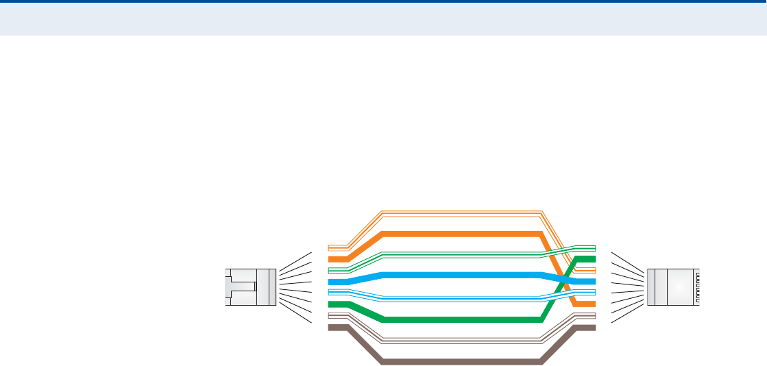
ß
ÐÐÛÒÜ×È
Ý
| Cables and Pinouts
Twisted-Pair Cable Assignments
95
ÝÎÑÍÍÑÊÛÎ É×Î×ÒÙ If the twisted-pair cable is to join two ports and either both ports are
labeled with an "X# (MDI-X) or neither port is labeled with an "X# (MDI), a
crossover must be implemented in the wiring.
Figure 61: Crossover Wiring
ɸ·¬»ñÑ®¿²¹»Í¬®·°»
Ñ®¿²¹»
ɸ·¬»ñÙ®»»²Í¬®·°»
ï
î
í
ì
ë
ê
é
è
ï
î
í
ì
ë
ê
é
è
Û×ßñÌ×ßëêèÞÎÖóìëÉ·®·²¹Í¬¿²¼¿®¼
ïðñïððÞßÍÛóÌÈÝ®±--±ª»®Ý¿¾´»
Û²¼ß
Û²¼Þ
Ù®»»²
Þ´«»
ɸ·¬»ñÞ´«»Í¬®·°»
Þ®±©²
ɸ·¬»ñÞ®±©²Í¬®·°»
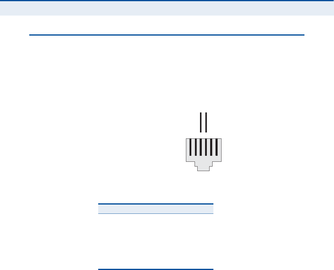
ß
ÐÐÛÒÜ×È
Ý
| Cables and Pinouts
RJ-11 Port
96
ÎÖóïï ÐÑÎÌ
Standard telephone RJ-11 connectors and cabling can be found in several
common wiring patterns. These six-pin connectors can accommodate up to
three wire pairs (three telephone lines), but usually only one or two pairs
of conductor pins and wires are implemented.
The RJ-11 port on this device contains only one wire pair on the inner pins
(3 and 4).
Figure 62: RJ-11 Port Pinout
Table 8: RJ-11 Port Pinout
Pin Signal Name Wire Color
1Not used
2Not used
3Line 1 RingRed or Blue/White
4Line 1 TipGreen or White/Blue
5Not used
6Not used
ïîíìëê
λ¼±®
Þ´«»ñɸ·¬»
Ù
®»»²±®
ɸ·¬»
ñÞ´
«»
ÎÌ
Îãη²¹ÌãÌ·°

97
ÙÔÑÍÍßÎÇ
ïðÞßÍÛóÌ IEEE 802.3-2005 specification for 10 Mbps Ethernet over two pairs of
Category 3 or better UTP cable.
ïððÞßÍÛóÌÈ IEEE 802.3-2005 specification for 100 Mbps Fast Ethernet over two pairs of
Category 5 or better UTP cable.
ßÝÝÛÍÍ ÐÑ×ÒÌ An Wi-Fi internetworking device that seamlessly connects wired and
wireless networks.
ßËÌØÛÒÌ×ÝßÌ×ÑÒ The process to verify the identity of a client requesting network access.
ßËÌÑóÒÛÙÑÌ×ßÌ×ÑÒ Signalling method allowing each node to select its optimum operational
mode (speed and duplex mode) based on the capabilities of the node to
which it is connected.
ÞßÍÛ ÍÌßÌ×ÑÒ A WIMAX service provider!s equipment that is installed at a fixed location
to provide network connectivity for subscriber stations within a defined
service area.
ÞÛßÝÑÒ A signal periodically transmitted from a Wi-Fi access point that is used to
identify the network and maintain contact with wireless clients.
Ý×ÒÎ Carrier-to-Interference-Plus-Noise Ratio. A measurement of the channel
quality in a WiMAX link. Subscriber stations measure the received CINR
and send the information back to the base station. The base station can
then adjust modulation and coding for the link to optimize throughput.
ÝÛÒÌÛÎ ÚÎÛÏËÛÒÝÇ The radio frequency at the center of a WiMAX channel. WiMAX channels
can be of different widths (the channel bandwidth) and the transmitted
radio signal is spread across the full width of the channel.
ÝØßÒÒÛÔ ÞßÒÜÉ×ÜÌØ The range of frequencies occupied by a WiMAX radio signal. The amount of
information that can be transmitted in a radio signal is related to the
channel bandwidth, which is measured in Megahertz (MHz). WiMAX
supports a range of channel bandwidths that can be defined by the service

Ù
ÔÑÍÍßÎÇ
98
operator depending on performance requirements, operating preferences,
and regulatory constraints.
ÝÐÛ Customer-Premises Equipment. Terminal equipment provided by a service
provider that is located at a subscriber!s premises and supports a
communication channel between a customer and the service provider.
ÜÒÍ Domain Name System. A system used for translating host names for
network nodes into IP addresses.
ÜØÝÐ Dynamic Host Configuration Protocol. Provides a framework for passing
configuration information to hosts on a TCP/IP network. DHCP is based on
the Bootstrap Protocol (BOOTP), adding the capability of automatic
allocation of reusable network addresses and additional configuration
options.
ÛÒÝÎÇÐÌ×ÑÒ Data passing between a base station and subscribers uses encryption to
protect from interception and evesdropping.
ÛÌØÛÎÒÛÌ A popular local area data communications network, which accepts
transmission from computers and terminals.
ÛßÐ Extensible Authentication Protocol. An authentication protocol used to
authenticate subscribers. EAP is used with TLS or TTLS authentication to
provide "mutual authentication# between a subscriber and a WiMAX
network.
ØÌÌÐ Hypertext Transfer Protocol. HTTP is a standard used to transmit and
receive all data over the World Wide Web.
×ÝÓÐ Internet Control Message Protocol. A network layer protocol that reports
errors in processing IP packets. ICMP is also used by routers to feed back
information about better routing choices.
×ÛÛÛ èðîòïïÞThe Wi-Fi wireless standard that supports communications in the 2.4 GHz
band using Direct Sequence Spread Spectrum (DSSS). The standard
provides for data rates of 1, 2, 5.5, and 11 Mbps.
×ÛÛÛ èðîòïïÙThe Wi-Fi wireless standard that supports communications in the 2.4 GHz
band using using Orthogonal Frequency Division Multiplexing (OFDM). The
standard provides for data rates of 6, 9, 11, 12, 18, 24, 36, 48, 54 Mbps.
IEEE 802.11g is also backward compatible with IEEE 802.11b.

Ù
ÔÑÍÍßÎÇ
99
×ÛÛÛ èðîòïêÛThe WiMAX standard that provides mobile broadband wireless access using
Scalable Orthogonal Frequency Division Multiple Access (SOFDMA).
×Ð ßÜÜÎÛÍÍ The Internet Protocol (IP) address is a numerical identification assigned to
a device that communicates in a network using the Internet Protocol.
×ÍÐ Internet Service Provider. A company that offers an access service that
connects customers to the Internet.
ÔÛÜ Light emitting diode. Used for indicating a device or network condition.
ÔßÒ Local Area Network. A group of interconnected computer and support
devices.
ÓßÝ ßÜÜÎÛÍÍ The physical layer address used to uniquely identify network nodes.
ÓÍóÝØßÐÊî Microsoft!s version 2 of the Challenge-Handshake Authentication Protocol.
Introduced by Microsoft with Windows 2000, MS-CHAPV2 (defined in RFC
2759) provides mutual authentication between peers using user names
and passwords.
ÑÜÚÓ Orthogonal Frequency Division Multiplexing. The air interface defined for
IEEE 802.11g Wi-Fi. OFDM allows multiple users to transmit in an allocated
band by dividing the bandwidth into many narrow bandwidth carriers.
ÎÖóìë ÝÑÒÒÛÝÌÑÎ A connector for twisted-pair wiring.
ÎÍÍ× Receive Signal Strength Indicator. A measurement of the strength of a
received wireless signal. The higher the RSSI value, the stronger the
received signal from the antenna.
ÎÑßÓ×ÒÙ The process where a WiMAX subscriber can move onto another operator!s
network while maintaining a continuous connection.
ÍÑÚÜÓß Scalable Orthogonal Frequency Division Multiple Access. The air interface
defined for mobile WiMAX. SOFDMA is a multiple access method that allows
simultaneous transmissions to and from several users, employing a
subchannel structure that scales with bandwidth.
ÍÛÎÊ×ÝÛ ÐÎÑÊ×ÜÛÎ See Internet Service Provider.

Ù
ÔÑÍÍßÎÇ
100
ÍÍ×Ü Service Set Identifier. A name that is sent in packets over a Wi-Fi network,
which functions as a password for clients connecting to the network. The
SSID differentiates one Wi-Fi network from another.
ÍÒÌÐ Simple Network Time Protocol. SNTP allows a device to set its internal
clock based on periodic updates from a Network Time Protocol (NTP)
server. Updates can be requested from a specific NTP server, or can be
received via broadcasts sent by NTP servers.
Í×Ó Subscriber Identity Module. A standard for a small removable integrated
circuit card that securely stores information used to identify a mobile
wireless subscriber.
ÍËÞÍÝÎ×ÞÛÎ ÍÌßÌ×ÑÒ A general term for a customer!s WIMAX terminal equipment that provides
connectivity with a base station.
ÌÝÐñ×Ð Transmission Control Protocol/Internet Protocol. Protocol suite that
includes TCP as the primary transport protocol, and IP as the network layer
protocol.
ÌÔÍ Transport Layer Security. An standard defined in RFC 5216, EAP-TLS is an
authentication protocol that provides strong security through the use of
client-side certificates.
ÌÌÔÍ Tunneled Transport Layer Security. EAP-TTLS is a protocol extension of
EAP-TLS. The authentication server is authenticated to the client using its
Certification Authority certificate, this establishes a secure "tunnel#
through which the client is then authenticated.
ËÎÔ Uniform Resource Locator. An easy-to-read character string that is used to
represent a resource available on the Internet. For example, "http://
www.url-example.com/.#
ËÌÐ Unshielded twisted-pair cable.
ÉÛÐ Wired Equivalent Privacy. WEP is the Wi-Fi security based on the use of
RC4 encryption keys. Wi-Fi devices without a valid WEP key are excluded
from the network.
ÐÍÕ WPA Pre-shared Key. PSK security can be used for small Wi-Fi networks
that may not have the resources to configure and maintain a RADIUS

Ù
ÔÑÍÍßÎÇ
101
server. WPA provides a simple operating mode that uses just a pre-shared
password for network access.
É×ÓßÈ The IEEE 802.16 standard for Worldwide Interoperability for Microwave
Access. The IEEE 802.16-2004 standard, known as "fixed WiMAX,#
supports only point-to-point links and has no support for mobility. The IEEE
802.16e-2005 standard, known as "mobile WiMAX,# is an amendment to
IEEE 802.16-2004 and supports mobility. Note that mobile WiMAX standard
is not backward compatible with the fixed WiMAX standard.

102
×ÒÜÛÈ
ß
AC power adapter 18
administrator password, setting 32
administrator settings 32
Advanced Setup menu 27
AES encryption 82
authentication
type 79
authentication options 80
auto-logout time 33
Þ
beacon interval 78
button, Reset 18
Ý
cable assignments 93
cable connections 21
channel setting 77
channels, maximum 91
checklist 20
client filter, enable 54
Codec 73
configuration, basic 25
contents, package 20
Ü
data beacon rate 78
default Key, WEP 81
default settings, restore 34
defaults, factory 34
DHCP server 45
discard ping 53
downloading software 33
DTIM setting 78
dynamic DNS 43
dynamic IP, cable modem 39
Û
encryption 79
encryption options 80
Ethernet ports 17
Ú
factory defaults, restoring 34
firewall protection 53
firmware update 33
fixed-IP xDSL 39
fragmentation threshold 78
frequency setting 77
Ù
Gateway address 40, 60
gateway function 21
Ø
hacker attack, prevention 53
hardware, description 15
×
IEEE 802.11g 75
configuring interface 76
initial configuration 23
installation, connecting cables 21
installing the device 20
IP address 40, 45
IP filters 54
IPsec 51
Ô
L2TP 39, 51
LAN status information 31
language selection 24, 33
LEDs 16, 17
logging, system 36
login, web 23
lost password, recovery 88
Ó
MAC address filters 56
MDI/MDI-X, automatic 17
messages, logging 36
Ò
NAT setting 48
network name, wireless 77

×
ÒÜÛÈ
103
Ñ
open system 79
operating frequency 90, 91
Ð
package checklist 20
panels, front and rear 15
password, setting 32
phone settings 72
ping discard 53
port indicators 16, 17
power socket 18
power supply, specifications 89
PPTP 39, 51
private IP 49
private port 49
proxy server port 66
Î
radio mode 76
rear panel sockets 18
reboot unit 37, 88
Reset button 18
resetting the unit 37, 88
RJ-45 ports 17
RTS threshold 78
Í
security, options 79
Setup Wizard
launching 25
Simple Network Time Protocol See SNTP
SIP settings 66
slot time 79
SNTP 35
enabling client 35
software update 33
SSID 77
static routing table 61
subnet mask 40, 45, 60
subscriber station 14
system clock, setting 35
system indicators 16, 17
system information 32
system log 36
system time 35
Ì
time updates 35
TKIP encryption 82
Ë
upgrading software 33
É
WAN connection type 31
web management interface
access 23
login 23
troubleshooting 88
WEP security 80
wireless network mode 76
Wizard, setup 25
WPA pre-shared key 81

RG300
E042011-CS-R01
149100000095W