Acer 5100 Users Manual S58M
7100 to the manual d8477a9c-4f4d-44a3-887b-6202b52d17fb
2015-01-25
: Acer Acer-5100-Users-Manual-211365 acer-5100-users-manual-211365 acer pdf
Open the PDF directly: View PDF ![]() .
.
Page Count: 120 [warning: Documents this large are best viewed by clicking the View PDF Link!]
- Veriton 5100/7100
- Table of Contents
- Ch.1 System Specifications
- Ch.2 System Utilities
- Ch.3 Machine Disassembly and Replacement
- Ch.4 Troubleshooting
- Ch.5 Jumper and Connector Information
- Ch.6 FRU (Field Replaceable Unit) List
- Ap.A Model Definition and Configuration
- Ap.B Test Compatible Components
- Ap.C Online Support Information
- Index

Veriton 5100/7100
Service Guide
PART NO.: 49.38H02.001/ 49.38H02.011
DOC. NO.: SG349-0007A/ SG350-0007A PRINTED IN TAIWAN
Service guide files and updates are available
on the AIPG/CSD web; for more information,
please refer to http://csd.acer.com.tw

II
Copyright
Copyright © 1999 by Acer Incorporated. All rights reserved. No part of this publication may be reproduced,
transmitted, transcribed, stored in a retrieval system, or translated into any language or computer language, in
any form or by any means, electronic, mechanical, magnetic, optical, chemical, manual or otherwise, without
the prior written permission of Acer Incorporated.
Disclaimer
The information in this guide is subject to change without notice.
Acer Incorporated makes no representations or warranties, either expressed or implied, with respect to the
contents hereof and specifically disclaims any warranties of merchantability or fitness for any particular
purpose. Any Acer Incorporated software described in this manual is sold or licensed "as is". Should the
programs prove defective following their purchase, the buyer (and not Acer Incorporated, its distributor, or its
dealer) assumes the entire cost of all necessary servicing, repair, and any incidental or consequential
damages resulting from any defect in the software.
Acer is a registered trademark of Acer Corporation.
Intel is a registered trademark of Intel Corporation.
Pentium and Pentium II/III are trademarks of Intel Corporation.
Other brand and product names are trademarks and/or registered trademarks of their respective holders.

III
Conventions
The following conventions are used in this manual:
Screen messages Denotes actual messages that appear
on screen.
NOTE Gives bits and pieces of additional
information related to the current
topic.
WARNING Alerts you to any damage that might
result from doing or not doing specific
actions.
CAUTION Gives precautionary measures to
avoid possible hardware or software
problems.
IMPORTANT Reminds you to do specific actions
relevant to the accomplishment of
procedures.

IV
Preface
Before using this information and the product it supports, please read the following general information.
1. This Service Guide provides you with all technical information relating to the BASIC CONFIGURATION
decided for Acer's "global" product offering. To better fit local market requirements and enhance product
competitiveness, your regional office MAY have decided to extend the functionality of a machine (e.g.
add-on card, modem, or extra memory capability). These LOCALIZED FEATURES will NOT be covered
in this generic service guide. In such cases, please contact your regional offices or the responsible
personnel/channel to provide you with further technical details.
2. Please note WHEN ORDERING FRU PARTS, that you should check the most up-to-date information
available on your regional web or channel. If, for whatever reason, a part number change is made, it will
not be noted in the printed Service Guide. For ACER-AUTHORIZED SERVICE PROVIDERS, your Acer
office may have a DIFFERENT part number code to those given in the FRU list of this printed Service
Guide. You MUST use the list provided by your regional Acer office to order FRU parts for repair and
service of customer machines.

V
Table of Contents
Chapter 1 System Specifications 1
Overview . . . . . . . . . . . . . . . . . . . . . . . . . . . . . . . . . . . . . . . . . . . . . . . . . . . . . . . 1
Features. . . . . . . . . . . . . . . . . . . . . . . . . . . . . . . . . . . . . . . . . . . . . . . . . . . . . . . 2
Front Panel-Veriton 5100. . . . . . . . . . . . . . . . . . . . . . . . . . . . . . . . . . . . . . . . . . . 4
Rear Panel-Veriton 5100 . . . . . . . . . . . . . . . . . . . . . . . . . . . . . . . . . . . . . . . . . . . 6
Front Panel-Veriton 7100. . . . . . . . . . . . . . . . . . . . . . . . . . . . . . . . . . . . . . . . . . . 8
Rear Panel-Veriton 7100 . . . . . . . . . . . . . . . . . . . . . . . . . . . . . . . . . . . . . . . . . . 10
Main Board Layout. . . . . . . . . . . . . . . . . . . . . . . . . . . . . . . . . . . . . . . . . . . . . . . 12
Keyboard . . . . . . . . . . . . . . . . . . . . . . . . . . . . . . . . . . . . . . . . . . . . . . . . . . . . . . 13
Hardware Specifications and Configurations. . . . . . . . . . . . . . . . . . . . . . . . . . . 16
Power Management Functions . . . . . . . . . . . . . . . . . . . . . . . . . . . . . . . . . . . . . 25
Chapter 2 System Utilities 27
Entering Setup. . . . . . . . . . . . . . . . . . . . . . . . . . . . . . . . . . . . . . . . . . . . . . . . . . 28
System Information . . . . . . . . . . . . . . . . . . . . . . . . . . . . . . . . . . . . . . . . . . . . . . 30
Product Information . . . . . . . . . . . . . . . . . . . . . . . . . . . . . . . . . . . . . . . . . . . . . . 32
Disk Drives. . . . . . . . . . . . . . . . . . . . . . . . . . . . . . . . . . . . . . . . . . . . . . . . . . . . . 33
Onboard Peripherals . . . . . . . . . . . . . . . . . . . . . . . . . . . . . . . . . . . . . . . . . . . . . 37
Power Management. . . . . . . . . . . . . . . . . . . . . . . . . . . . . . . . . . . . . . . . . . . . . . 39
Boot Options . . . . . . . . . . . . . . . . . . . . . . . . . . . . . . . . . . . . . . . . . . . . . . . . . . . 41
Date and Time . . . . . . . . . . . . . . . . . . . . . . . . . . . . . . . . . . . . . . . . . . . . . . . . . . 43
System Security . . . . . . . . . . . . . . . . . . . . . . . . . . . . . . . . . . . . . . . . . . . . . . . . 44
Advanced Options . . . . . . . . . . . . . . . . . . . . . . . . . . . . . . . . . . . . . . . . . . . . . . . 47
Load Default Settings . . . . . . . . . . . . . . . . . . . . . . . . . . . . . . . . . . . . . . . . . . . . 52
Abort Settings Change. . . . . . . . . . . . . . . . . . . . . . . . . . . . . . . . . . . . . . . . . . . . 53
Exiting Setup . . . . . . . . . . . . . . . . . . . . . . . . . . . . . . . . . . . . . . . . . . . . . . . . . . . 54
Chapter 3 Machine Disassembly and Replacement 55
Disassembling Veriton 5100 . . . . . . . . . . . . . . . . . . . . . . . . . . . . . . . . . . . . . . . 56
Disasembling the Veriton 7100 . . . . . . . . . . . . . . . . . . . . . . . . . . . . . . . . . . . . . 63
Chapter 4 Troubleshooting 71
Power-On Self-Test (POST) . . . . . . . . . . . . . . . . . . . . . . . . . . . . . . . . . . . . . . . 72
POST Error Messages List . . . . . . . . . . . . . . . . . . . . . . . . . . . . . . . . . . . . . . . . 73
Error Symptoms List . . . . . . . . . . . . . . . . . . . . . . . . . . . . . . . . . . . . . . . . . . . . . 75
Undetermined Problems . . . . . . . . . . . . . . . . . . . . . . . . . . . . . . . . . . . . . . . . . . 79
Chapter 5 Jumper and Connector Information 81
Jumpers and Connectors. . . . . . . . . . . . . . . . . . . . . . . . . . . . . . . . . . . . . . . . . . 81
Chapter 6 FRU (Field Replaceable Unit) List 85
Veriton 5100 Exploded Diagram . . . . . . . . . . . . . . . . . . . . . . . . . . . . . . . . . . . . 86
Veriton 7100 Exploded Diagram . . . . . . . . . . . . . . . . . . . . . . . . . . . . . . . . . . . . 87
Appendix A Model Definition and Configuration 97
Veriton 5100 . . . . . . . . . . . . . . . . . . . . . . . . . . . . . . . . . . . . . . . . . . . . . . . . . . . 97
Veriton 7100 . . . . . . . . . . . . . . . . . . . . . . . . . . . . . . . . . . . . . . . . . . . . . . . . . . . 98
Appendix B Test Compatible Components 99
MS DOS V6.22 Environment Test . . . . . . . . . . . . . . . . . . . . . . . . . . . . . . . . . . 100
Microsoft Windows 98SE (EN/TW) Environment Test. . . . . . . . . . . . . . . . . . . 101
Microsoft Windows 2000 Professional Environment Test . . . . . . . . . . . . . . . . 103

VI
Table of Contents
Microsoft Win95/NT 4.0 Workstation Environment Test . . . . . . . . . . . . . . . . . 104
IBM OS/2 Warp 4.0 Environment Test . . . . . . . . . . . . . . . . . . . . . . . . . . . . . . 105
Novell Netware 4.12 & 5.1 Environment Test . . . . . . . . . . . . . . . . . . . . . . . . . 106
SCO UNIX/Red Hat Linux Environment Test . . . . . . . . . . . . . . . . . . . . . . . . . 107
Appendix C Online Support Information 109
Index 111

Chapter 1 1
Overview
The Veriton 5100/7100 supports Intel® Pentium III Flip Chip-Pin Grid Array (FC-PGA) processor based Micro
ATX, IBM PC/AT compatible system with PCI/AGP bus.
System Specifications
Chapter 1

2Chapter 1
Features
Performance
!Intel® Pentium III processor which uses the FC-PGA 370 socket.
!128/256 KB PBSRAM L2 cache incorporated in Intel® Pentium III (Coppermine) processor.
!Maximum of 512 MB SDRAM within 3 DIMM slots up to 133MHz.
!Support AGP 2.0 including 4x AGP data transfers.
!Integrated LAN Controller (82801BA).
!3.5-inch and 5.25-inch floppy disk drives.
!CD-ROM/DVD-ROM drive
!High capacity, Enhanced-IDE hard disk
!Power management features
!CPU SMM (System Management Mode), STOP clock control
!On-board PCI master enhanced local bus IDE (Embedded in 82801BA chipset).
!PIO mode 4
!Ultra DMA/100, Ultra DMA/66 & Ultra DMA/33 modes
!Plug-and-Play (PnP) feature
!Power management features
!Support for APM-1.2 for Non-ACPI implementations
!ACPI 1.0 compliant
!Software shutdown for Windows 95/98
!Hardware monitor function (only support SMB)
Multimedia
!3-D quality audio system via onboard audio controller
!Audio-in/Line-in, Audio-out/Line-out, Headphone-in, Mic-in, and Game/MIDI interface
Connectivity
!One AGP and three PCI slots
!PS/2 mouse and keyboard interface
!Two serial and one parallel interface
!Four USB ports ( available on front and rear panels)
!High-speed fax/data PCI modem (optional)
!10Base-T/100Base-TX network support with remote wake-up function

Chapter 1 3
Human-centric design and ergonomics
!Slim desktop form factor
!Separate computer stand and rubber stands for quick and easy positioning
!Space-saver solution
!Accessible I/O ports
!Easy-to-open housing design for quick upgrade
4Chapter 1
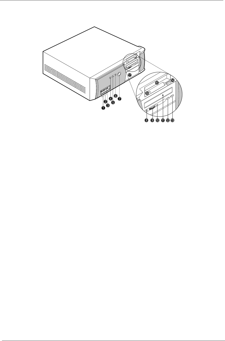
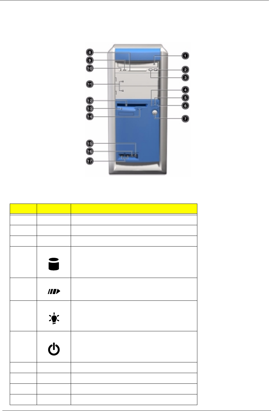
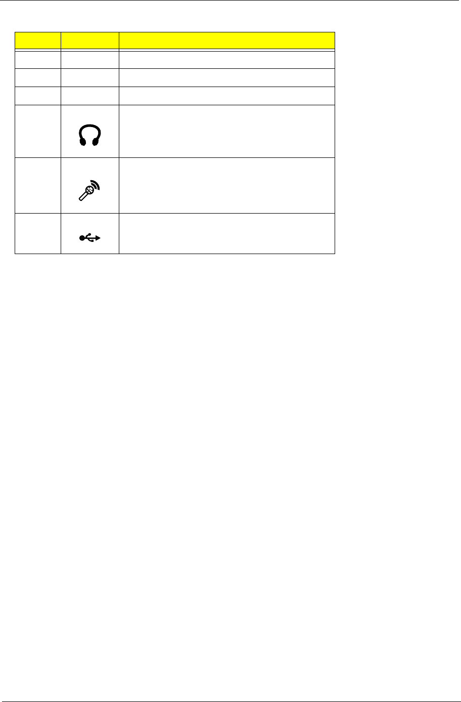
Front Panel-Veriton 5100
Chapter 1 5
NOTE: The system has two microphone-in ports (front and rear). However, you can not use both of them at
the same time. The default setting for your system enables the microphone-in port at the back and
disables the one in front. You have to enable the front microphone-in port to be able to use it.
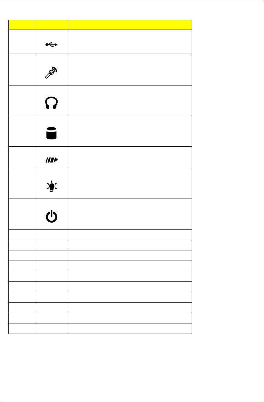
Label Icon Description
1 USB Ports
2 Microphone-in Port*
3 Speaker-out/Line-out Port
4 Hard Disk Drive Activity Light-emitting Diode (LED)
5 System Activity LED
6 Power LED
7 Power Switch
8 CD-ROM/DVD-ROM Headphone/Earphone Port
9 Volume Tuner
10 CD-ROM/DVD-ROM LED
11 CD-ROM/DVD-ROM Tray
12 Fast Forward/Skip Button
13 Stop/Eject Button
14 Floppy Disk Drive Eject Button
15 3.5-inch Floppy Disk Drive
16 Floppy Disk Drive LED
17 5.25-inch Drive Bays
6Chapter 1
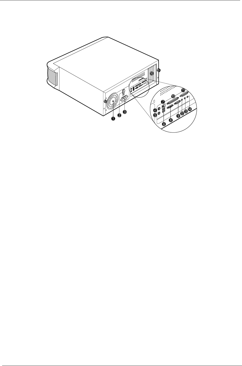
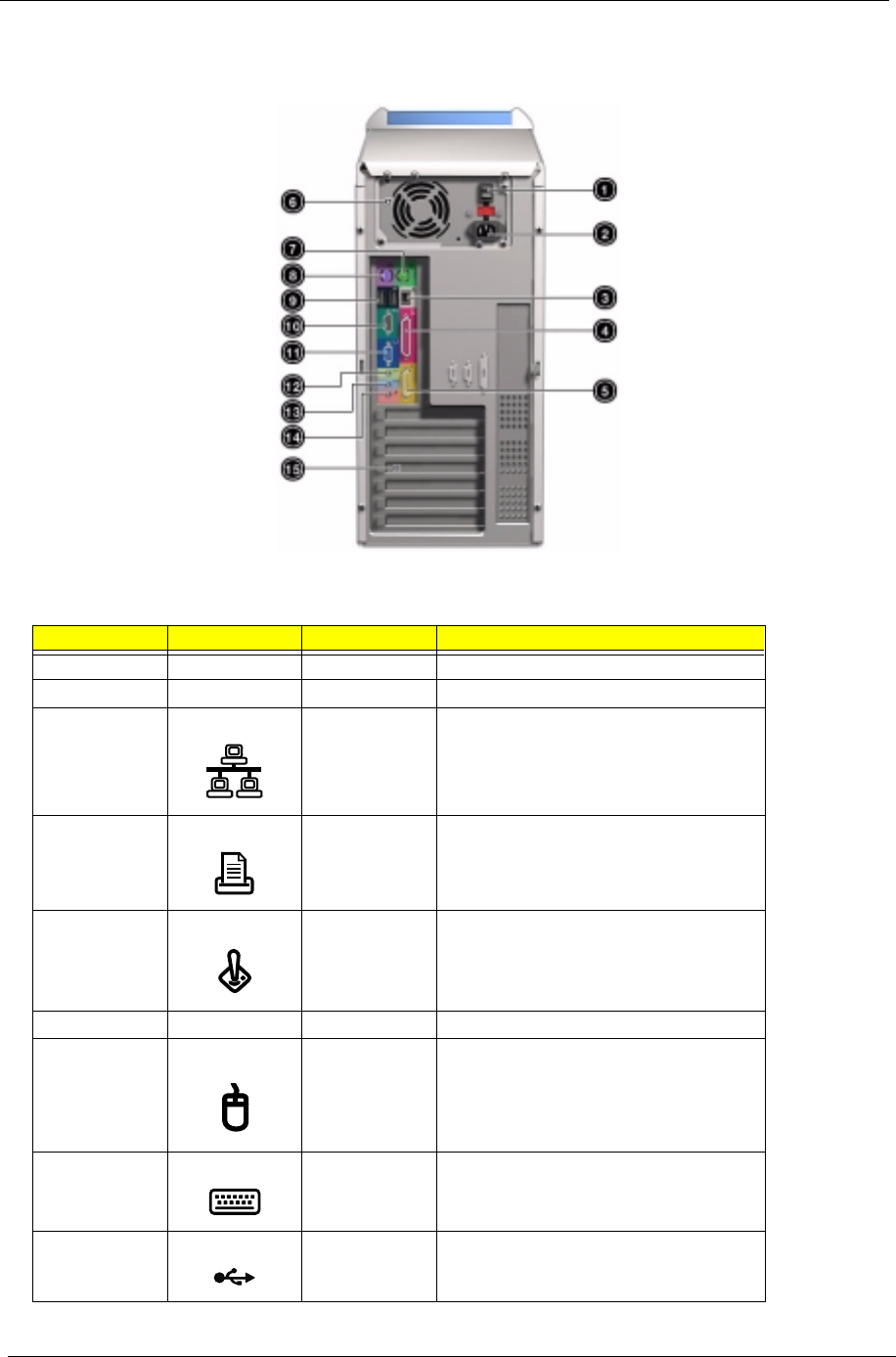
Rear Panel-Veriton 5100
Chapter 1 7
NOTE: The system has two microphone-in ports (front and rear). However, you can not use both of them at
the same time. The default setting for your system enables the microphone-in port at the back and
disables the one in front. You have to enable the front microphone-in port to be able to use it.
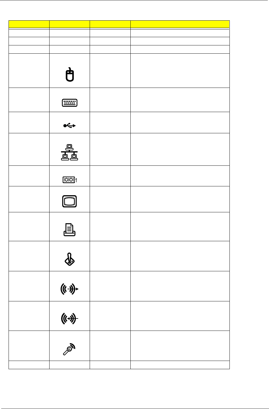
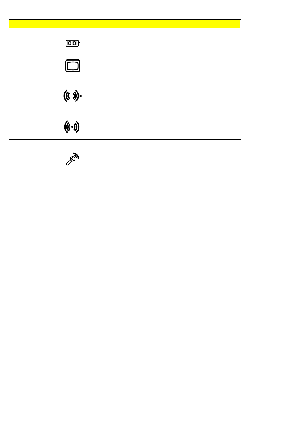
Label Icon Color Description
1 Power Supply
2 Power Switch
3 Power Cord Socket
4 Green PS/2 Mouse Port
5 Purple PS/2 Keyboard Port
6 Black USB Ports
7 White Network Port
8 Teal or Turquoise Serial Port
9 Blue CRT/LCD Monitor Port
10 Burgundy Parallel/Printer Port
11 Gold Game/MIDI Port
12 Lime Audio-out/Line-out Jack
13 Light blue Audio-in/Line-in Jack
14 Microphone-in Port *
15 Expansion Slots
8Chapter 1
Front Panel-Veriton 7100
The computer’s front panel consists of the following:
Label Icon Description
1 CD-ROM/DVD-ROM tray
2 Stop/Eject Button
3 Skip/Forward Button
4 Hard disk drive activity light-emitting diode (LED)
5 System activity LED
6 Power LED
7 Power button
8 CD-ROM/DVD-ROM LED
9 Volume Tuner
10 CD-ROM/DVD-ROM Headphone/Earphone port
11 5.25-inch drive bays
Chapter 1 9
* The system has two microphone-in ports (front and rear). However, you can not use both of them at the same
time. The default setting for your system enables the microphone-in port at the back and disables the one in
front. You have to enable the front microphone-in port to be able to use it.
12 3.5-inch floppy disk drive
13 Floppy disk drive LED
14 Floppy disk drive eject button
15 Speaker-out/Line-out port
16 Microphone-in port *
17 USB ports
Label Icon Description
10 Chapter 1
Rear Panel-Veriton 7100
Label Icon Color Description
1 Power Switch
2 Power cord socket
3 White Network port
4 Burgundy Parallel/printer port
5 Gold Game/MIDI port
6 Power Supply
7 Green PS/2 mouse port
8 Purple PS/2 keyboard port
9BlackUSB ports
Chapter 1 11
* The system has two microphone-in ports (front and rear). However, you can not use both of them at the same
time. The default setting for your system enables the microphone-in port at the back and disables the one in
front. You have to enable the front microphone-in port to be able to use it.
10 Teal or Turquoise Serial port
11 Blue CRT/LCD Monitor port
12 Lime Audio-out/Line-out jack
13 Light blue Audio-in/Line-in jack
14 Microphone-in port *
15 Expansion slots
Label Icon Color Description
12 Chapter 1
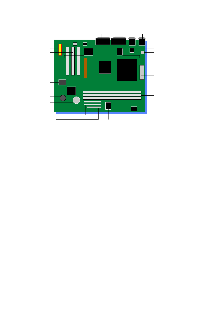
Main Board Layout
1 Audio Power AMP 14 FDD Connector
2 MIDI/Game (Upper), Line-Out (Left),
Line-In (Middle), and Mic-In Ports
(Right)
15 EIDE Connector
3 Parallel Port, VGA Port and Serial Port
1
16 Battery
4 Network Port and USB Ports 17 Buzzer
5 PS/2 Mouse Port and Keyboard Port 18 Intel 82801BA Chipset
6 Transformer 19 4MB FWH
7 FAN Connector 20 Intel 82815 Chipset
8 Platform LAN Connector 21 AGP
9 Socket 370 CPU 22 Super I/O Chipset
10 Power Connector 23 3 PCI
11 3 DIMM Sockets 24 CNR
12 H/W Mon. AD1024 25 Audio Chipset
13 Clock Generator
9
5
16
14
4
10
13
11
32
23
20
7
18
15
22
21
19
12
25
1
17
6
8
24
9
5
16
14
4
10
13
11
32
23
20
7
18
15
22
21
19
12
25
1
17
6
8
24
Chapter 1 13
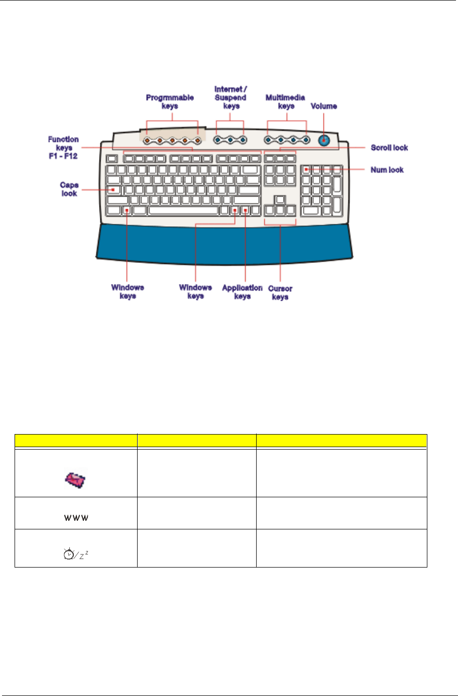
Keyboard
The keyboard has full-sized keys that include separate cursor keys, two Windows keys, and twelve function
keys.
Programmable keys
The programmable keys help you directly access a URL (Web site) or launch any program, files, or application
in your system. The fifth key is set to launch the media player. If you want to configure the settings of each key
right click on the Magic Keyboard icon located on the desktop.
Internet/Suspend keys
The internet/Suspend keys consist of three buttons:
Icons Key Description
E-mail Launches your e-mail application.
Web Browser Launches your current default browser.
Suspend/Resume Press this button to put the system to sleep.
Press again to wake up.
14 Chapter 1
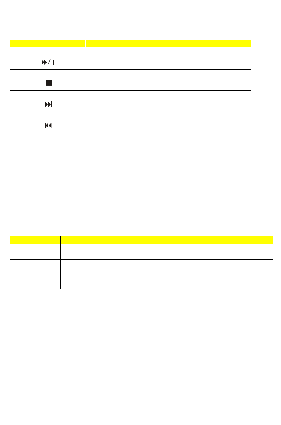
Multimedia keys
Allow you to play, pause, stop, step forward, or step back a song or movie conveniently using your keyboard.
Volume control/Mute
The volume control/Mute knob controls the speaker volume. Turn it clockwise or counterclockwise to adjust
the volume. Press it to toggle between mute and sound.
Cursor keys
The cursor keys, also called the arrow keys, let you move the cursor around the screen. They serve the same
function as the arrow keys on the numeric keypad when the Num Lock is toggled off.
Lock keys
The keyboard has three lock keys which you can toggle on and off to switch between two functions.
Icons Key Description
Play/Pause Press to start playing an audio or video
file. Press again to pause.
Stop Press to stop playing the audio or video
file.
Forward Press to skip forward to the next file and
start playing.
Backward Press to skip backward to the previous
file and start playing.
Lock Key Description
Caps Lock When activated, all alphabetic characters typed appear in uppercase (same function as pressing
Shift + <letter>).
Num Lock When activated, the keypad is set to numeric mode, i.e., the keys will function as a calculator
(complete with arithmetic operators such as +, -, x, and /).
Scroll Lock When activated, the screen moves one line up or down when you press the up arrow or down
arrow respectively. Take note that Scroll Lock may not work with some applications.

Chapter 1 15
Windows keys
The keyboard has two keys that perform Windows-specific functions.
Key Description
Windows logo key Start button. Combinations with this key perform special functions, such as:
!Windows + Tab: Activate the next Taskbar button
!Windows + E: Explore My Computer
!Windows + F: Find Document
!Windows + M: Minimize All
!Shift + Windows + M: Undo Minimize All
!Windows + R: Display the Run dialog box
Application key Opens the application’s context menu (same function as clicking the right button of
the mouse).
16 Chapter 1
Hardware Specifications and Configurations
NOTE: The BIOS can be overwritten/upgraded using the AFLASH utility (AFLASH.EXE).
Processor
Item Specification
Type Intel® Pentium III- Coppermine processors
Slot Socket 370
Speed Internal : 450/500/533/550/600/667/733/800/866 MHz
External: 100/133 MHz
Minimum operating speed 0 MHz (If Stop CPU Clock in Sleep State the BIOS Setup is set to Enabled.)
Voltage Processor voltage can be detected by the system without setting any jumper.
BIOS
Item Specification
BIOS code programmer Award
BIOS version V4.0
BIOS ROM type Flash ROM
BIOS ROM size 4Mbits
BIOS ROM package 32-pin DIP package
Support protocol PCI 2.1, APM1.2, DMI 2.00.1, E-IDE, ACPI 1.0, ESCD 1.03, ANSI ATA 3.0, PnP
1a, Bootable CD-ROM 1.0, ATAPI
Boot from CD-ROM feature Yes
Support to LS-120 drive Yes
Support to BIOS boot block feature No
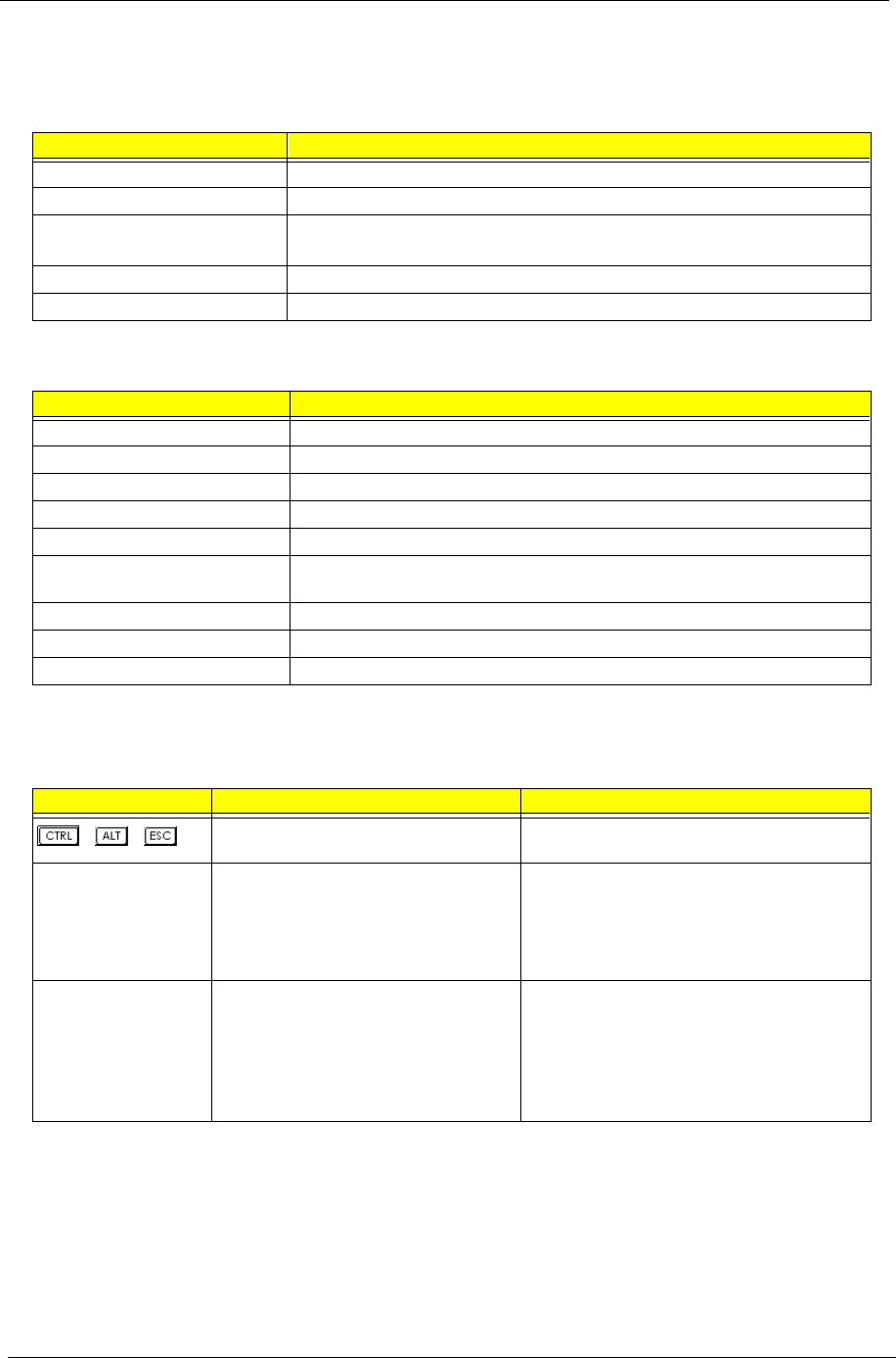
BIOS Hotkey List
Hotkey Function Description
++ Enter BIOS Setup Utility Press while the system is booting to enter BIOS
Setup Utility.
F8 Enable hidden page of BIOS Setup Utility Press in BIOS Setup Utility main menu screen,
the Advanced Options menu then appears.
The items on the Advanced Options menu are:
Memory/Cache Options
PnP/PCI Options
Alt + F4 Enable hidden page of BIOS Setup Utility Press in BIOS Setup Utility main menu screen,
the Advanced Options menu then appears.
The items on the Advanced Options menu are:
Memory/Cache Options
PnP/PCI Options
Chips Options
17
This section has two table lists, system memory specification and the possible combinations of memory
module.
NOTE: For Memory Combinations-133 MHz, if memory is double-sided, only slot 1 and slot 2 will work. The
maximum memory size of S58M is 512M. Users can make different combinations of double-sided
memory in slot 1 and slot 2; single-sided memory in slot 1, 2, and 3, but, the total memory should not go
beyond 512M.
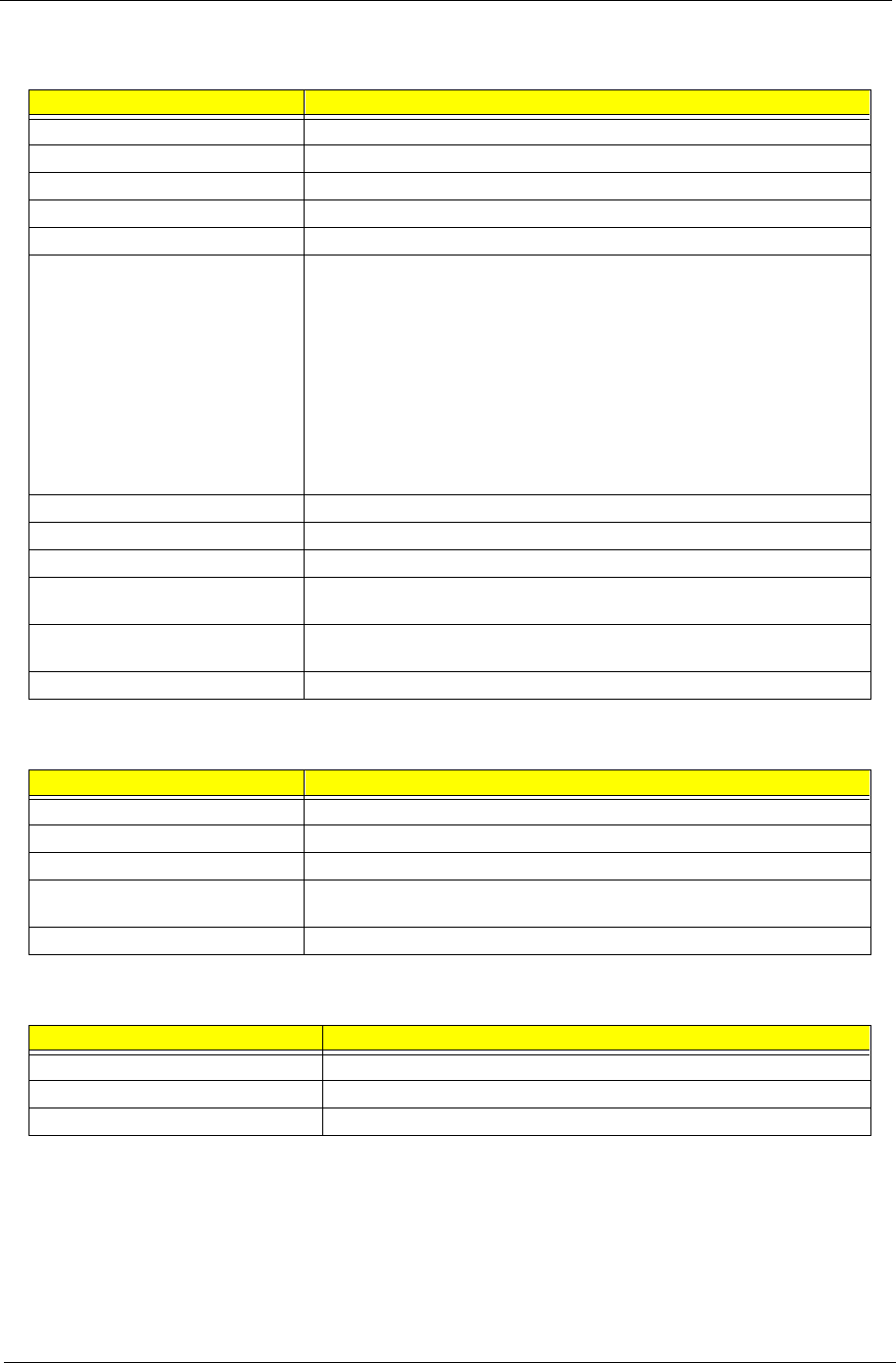
System Memory
Item Specification
Memory socket number 3 sockets (3 banks)
Support memory size per socket 64/128/256MB
Support maximum memory size 512MB
Support memory type SDRAM
Support memory speed 100/133MHz (PC100/ PC133) (for Local Bus speed 100/133MHz)
Support memory voltage 3.3 V
Support memory module package 168-pin DIMM
Support to parity check feature Yes
Support to Error Correction Code (ECC)
feature.
Yes
Memory module combinations You can install memory modules in any combination as long as they match
the Memory Combination specifications.
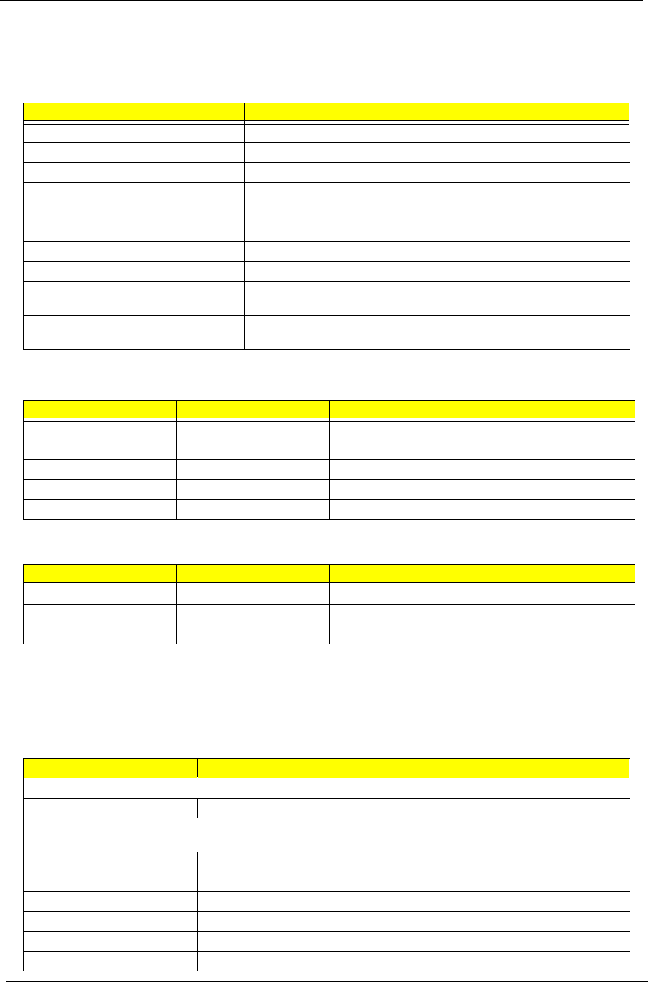
Memory Combinations-100 MHz
DIMM 1 DIMM 2 DIMM 3 TOTAL
128M 128M 128M 384M
256M 256M 0M 512M
64M 64M 64M 192M
32M 32M 32M 96M
16M 16M 16M 48M
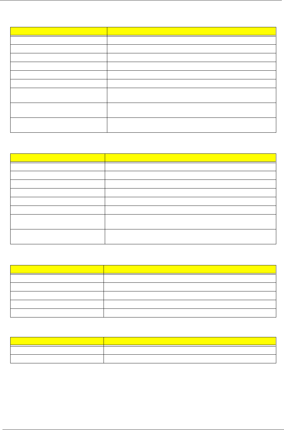
Memory Combinations-133 MHz
DIMM 1 DIMM 2 DIMM 3 TOTAL
256/DS M 256/DS M 0M 512M
64/SS M 64/SS M 64/SS M 192M
128/SS M 128/SS M 128/SS M 384M
Cache Memory
Item Specification
First-Level Cache Configurations
Cache function control Enable/Disable by BIOS Setup (Advanced options)
Second-Level Cache Configurations
Below information is only applicable to system with installed Pentium III processor.
L2 Cache RAM type PBSRAM
L2 Cache RAM size 128/256 KB
L2 Cache RAM speed One-half the processor core clock frequency
L2 Cache RAM voltage Pentium III processor: 1.65V
L2 Cache function control Enable/Disable by BIOS Setup
L2 Cache scheme Fixed in write-back
S58M-Ch1.fm Page 17 Thursday, August 3, 2000 9:41 AM

18 Chapter 1
*32 - 24bpp color data is processed using a 32bpp data format.
NOTE: You may disable the on-board video function in the BIOS Utility.
Video Interface
Item Specification
Video controller Embedded in Intel 82801BA ICH II
Video controller resident bus AGP bus
Video interface support Video YUV texture in all texture formats
H/W DVD accelerator
Display Screen Resolution Bits Per Pixel
(Frequency in Hz)
8-bit Indexed
Bits Per Pixel
(Frequency in Hz)
16-bit Indexed)
Bits Per Pixel
(Frequency in Hz)
24-bit Indexed
320x240 70 70 70
320x240 70 70 70
352x480 70 70 70
352x576 70 70 70
400x300 70 70 70
512x384 70 70 70
640x400 70 70 70
640x480 60, 70, 72, 75, 85 60, 70, 72, 75, 85 60, 70, 72, 75, 85
720x480 75, 85 75, 85 75, 85
720x576 60, 75, 85 60, 75, 85 60, 75, 85
800x600 60, 70, 72, 75, 85 60, 70, 72, 75, 85 60, 70, 72, 75, 85
1024x768 60, 70, 72, 75, 85 60, 70, 72, 75, 85 60, 70, 72, 75, 85
1152x864 60, 70, 72, 75, 85 60, 70, 72, 75, 85 60, 70, 72, 75, 85
1280x720 60, 75, 85 60, 75, 85 60, 75, 85
1280x960 60, 75, 85 60, 75, 85 60, 75, 85
1280x1024 60, 70, 72, 75, 85 60, 70, 72, 75, 85 60, 70, 72, 75, 85
1600x900 60, 75, 85 60, 75, 85 60, 75, 85
1600x1200 60, 70, 72, 75, 85 Not available Not available
Chapter 1 19
Audio Interface
Item Specification
Audio controller Embedded in Intel 82801BA ICH II
Audio controller resident bus AC’97 link
Audio function control Enable/disable by BIOS Setup
Mono or stereo Stereo
Resolution 16 bits
Compatibility AC’97 2.1 compliant
Sound Blaster Pro compatible
Mixed digital and analog high performance chip
Enhanced stereo full duplex operation
High performance PCI audio accelerator
Full native DOS games compatibility
High-Quality ESFM music synthesizer
MPU-401(UART mode) interface for wavetable synthesizers and MIDI devices
Integrated dual game port
Meets PC 97/PC98 and WHQL specifications
Music synthesizer Yes
Sampling rate 44.1 KHz
MPU-401 UART support Yes
Microphone jack Supported
On audio-I/O board (connects via CN8)
Headphone jack Supported
On audio-I/O board (connects via CN8)
Package QFP64
IDE Interface
Item Specification
IDE controller Embedded in Intel 82801BA ICH II
IDE controller resident bus PCI bus
Number of IDE channel 2 on-board: 40-pin hard disk drive connector,
Support IDE interface E-IDE (up to PIO mode 4 and Ultra DMA/33, Ultra DMA/66 and Ultra DMA/100
mode 2) ANSIS ATA rev.4.0 ATAPI
Support bootable CD-ROM Yes
Floppy disk drive Interface
Item Specification
Floppy disk drive controller Embedded in LPC 47B277
Floppy disk drive controller resident bus LPC
Support FDD format 360KB, 720KB, 1.2MB, 1.44MB, 2.88MB; 3-mode
20 Chapter 1
Parallel Port
Item Specification
Parallel port controller Embedded in LPC 47B277
Parallel port controller resident bus LPC
Number of parallel ports 1
Support ECP/EPP ECP / EPP 1.7 & 1.9
Connector type 25-pin D-type female connector
Parallel port function control Enable/disable by BIOS Setup
Optional ECP DMA channel
(in BIOS Setup)
DMA channel 1
DMA channel 3
Optional parallel port I/O address
(via BIOS Setup)
378h
278h
Optional parallel port IRQ
(via BIOS Setup)
IRQ5
IRQ7
Serial Port
Item Specification
Serial port controller Embedded in Intel 82801BA ICH II
Serial port controller resident bus LPC
Number of serial port 2
Serial ports location CN4, COM 2
16550 UART support Yes
Connector type 10-pin connector
Optional serial port I/O address
(via BIOS Setup)
3F8h, 2F8h, 3E8h, 2E8h
Optional serial port IRQ
(via BIOS Setup)
4, 3
Modem
Item Specification
Fax modem data baud rate (bps) 14.4K bps
Data modem data baud rate (bps) 56K bps
Voice modem Yes
Modem connector type RJ11
Full duplex Not applicable
USB Port
Item Specification
Universal HCI USB 1.0
USB Class Support legacy keyboard for legacy mode
Chapter 1 21
Memory Address Map
Address Size Function
000000 - 07FFFF 512KBytes Host Memory
080000 - 09FFFF 128KBytes Host/PCI Memory
0A0000 - 0BFFFF 128KBytes PCI/ISA Video Buffer Memory
0C0000 - 0C7FFF 32KBytes Video BIOS Memory
0C8000 - 0DFFFF 96Kbytes ISA Card BIOS & Buffer Memory
0E0000 - 0EFFFF 64Kbytes BIOS Extension Memory
Setup and Post Memory
PCI Development BIOS
0F0000 - 0FFFFF 64Kbytes System BIOS Memory
100000 - UPPER LIMIT Main Memory
UPPER LIMIT - 4GBytes PCI Memory
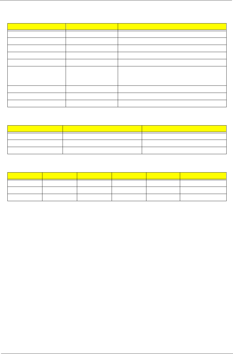
PCI INTx# and IDSEL Assignment Map
PCI INTx # PCI Devices Device IDSEL: ADxx
INTA# PCI Slot 1 AD16
INTB# PCI slot 2 AD17
INTC# PCI slot 3 AD22
PCI Slot IRQ Routing Map
PCI INTX# INTA INTB INTC INTD Bus Mastering
PCI 1 Route 1 Route 2 Route 3 Route 4 Enabled
PCI 2 Route 4 Route 1 Route 2 Route 3 Enabled
PCI 3 Route 3 Route 4 Route 1 Route 2 Enabled
22 Chapter 1
NOTE: N - Not in use
I/O Address Map
Hex Range Devices
000-00F
020-021
040-043
060-060
061-061
070-071
081-08F
0A0-0A1
0C0-0DF
0F0-0FF
170-177
1F0-1F7
278-27F
2F8-2FF
378-37F
3F0-3F5
3F6-3F6
3F7-3F7
3F8-3FF
0CF8
0CFC
778-77A
DMA Controller-1
Interrupt Controller-1
System Timer
Keyboard Controller 8742
System Speaker
CMOS RAM Address and Real Time Clock
DMA Controller-2
Interrupt Controller-2
DMA Controller-2
Math Co-Processor
Secondary IDE
Primary IDE
Parallel Printer Port 2
Serial Asynchronous Port 2
Parallel Printer Port 1
Floppy Disk Controller
Secondary IDE
Primary IDE
Serial Asynchronous Port 1
Configuration Address Register
Configuration Data Register
Parallel Printer Port 1
IRQ Assignment Map
IRQx System Devices Add-On-Card Devices
IRQ0 Timer N
IRQ1 Keyboard N
IRQ2 Cascade Interrupt Control N
IRQ3 Serial Alternate Reserved
IRQ4 Serial Primary Reserved
IRQ5 Parallel Port (Alternate) Reserved
IRQ6 Floppy Diskette Reserved
IRQ7 Parallel Port Reserved
IRQ8 Real Time Clock N
IRQ9 N Reserved
IRQ10 N Reserved
IRQ11 N Reserved
IRQ12 PS/2 Mouse Reserved
IRQ13 Math Co-processor Exception N
IRQ14 Fix Diskette Reserved
IRQ15 Fix Diskette Reserved
Chapter 1 23
NOTE: N - Not in use
DRQ Assignment Map
DRQx System Devices Add-On-Card Devices
DRQ0 N Reserved
DRQ1 N Reserved
DRQ2 Floppy Diskette N
DRQ3 N Reserved
DRQ4 Cascade N
DRQ5 N Reserved
DRQ6 N Reserved
DRQ7 N Reserved
Main Board Major Chips
Item Controller
North Bridge Intel 82815 GMCH
South Bridge Intel 82801BA ICH II
Super I/O controller SMSC LPC47B277
Audio controller Built-in Intel 82801 ICH
LAN controller Intel 82562EM
HDD controller Built-in Intel 82801BA ICH II
Keyboard controller Built-in Intel 82801BA ICH II
RTC Built-in Intel 82801BA ICH II
Environmental Requirements
Item Specifications
Temperature
Operating +10 ~ +35°C
Non-operating -20 ~ +60°C (Storage package)
Humidity
Operating 20% to 80% RH
Non-operating 20% to 80% RH
Vibration
Operating (unpacked) 5 ~ 16.2 Hz: 0.38 mm
16.2~250 Hz: 0.2G
Non-operating (packed) 5 ~ 27.1 Hz: 0.6 G
27.1 ~ 50 Hz: 0.4 mm
50 ~ 500 Hz: 2 G
Mechanical Specifications
Item Specification
Weight
One 3.5 FDD and one 3.5 HDD
(without packing)
Depends on local configuration
Dimensions
(main footprint)
Veriton 5100:
24 Chapter 1
(This is for 145 power supply)
NOTE: 1. This "4A" includes the outlet supply current: 2A.
2. Measure at line input 90VRMS and maximum load condition.
NOTE: +5V and 3.3V total power is 100W max.
Switching Power Supply 145W
Input Frequency Frequency Variation Range
50Hz 47Hz to 53Hz
60Hz 57Hz to 63Hz
Input Voltage Variation Range
100 - 120 VRMS 90-132 VRMS
200 - 240 VRMS 180-264 VRMS
Input Current Measuring Range
4A 90 -132 VRMS
3A 180 - 264 VRMS
Output Requirements Regulation Current Rating
+5V +-5% 15A
+12V +-5% 3A
-12V +-10% 0.3A
+3.3V +-5% 12A
-5V +-10% 0A
+5Vaux +-5% 1A

Chapter 1 25
Power Management Functions
Device Standby Mode
!Independent power management timer for hard disk drive devices
(0-15 minutes, time step=1 minute).
!Hard disk drive goes into Standby mode (for ATA standard interface).
!Disable V-sync to control the VESA DPMS monitor.
!Resume method: device activated (Keyboard for DOS, keyboard & mouse for Windows).
!Resume recovery time: 3-5 sec.
Global Standby Mode
!Global power management timer (2-120 minutes, time step=10 minute).
!Hard disk drive goes into Standby mode (for ATA standard interface).
!Disable H-sync and V-sync signals to control the VESA DPMS monitor.
!Resume recovery time: 7-10 sec.
Suspend Mode
!Independent power management timer (2-120 minutes, time step=10 minutes) or pushing external
switch button
!CPU goes into SMM.
!CPU asserts STPCLK# and goes into the Stop Grant State.
!LED on the panel turns amber color.
!Hard disk drive goes into SLEEP mode (for ATA standard interface).
!Disable H-sync and V-sync signals to control the VESA DPMS monitor.
!Return to original state by pushing external switch button.
Suspend to RAM
!The system context is maintained in system memory
!Power is shut to non-critical circuits.
!Memory is retained, and refreshes continually.
!All clocks shut except RTC.
!Return to original state by pushing external switch button & “PME” events at ACPI mode.

26 Chapter 1

Chapter 2 27
Most systems are already configured by the manufacturer or the dealer. There is no need to run
Setup when starting the computer unless you get a Run Setup message.
The Setup program loads configuration values into the battery-backed nonvolatile memory called CMOS RAM.
This memory area is not part of the system RAM.
NOTE: If you repeatedly receive Run Setup messages, the battery may be bad. In this case, the system
cannot retain configuration values in CMOS.
Before you run Setup, make sure that you have saved all open files. The system reboots immediately after
you exit Setup.
System Utilities
Chapter 2
28 Chapter 2
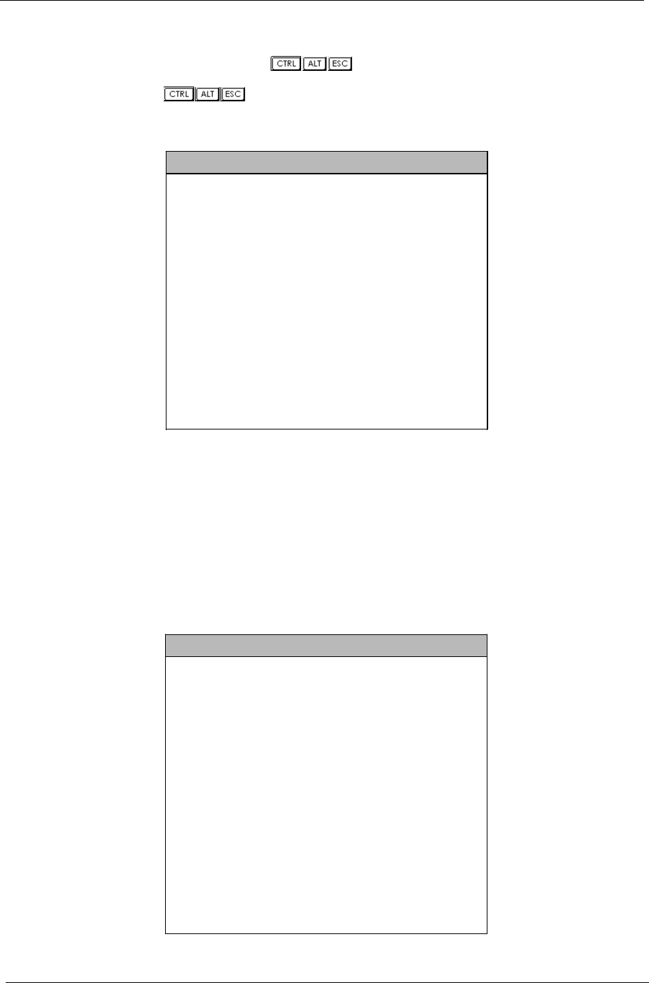
Entering Setup
To enter Setup, press the key combination .
NOTE: You must press simultaneously while the system is booting.
The Setup Utility main menu then appears:
The system supports two BIOS Utility levels: Basic and Advanced. The above screen is the BIOS Utility Basic
Level screen. It allows you to view and change only the basic configuration of your system.
If you are an advanced user, you may want to check the detailed configuration of your system. Detailed
system configurations are contained in the Advanced Level. To view the Advanced Level menu, press F8 or
the Alt + F4 keys simultaneously.
NOTE: The F8 and Alt + F4 keys work only when you are in the main menu. This means that you can activate
the advanced level and hidden information only when you are in the main menu.
The following screen shows the Advanced Level main menu:
Setup Utility
! System Information
! Product Information
! Disk Drives
! Onboard Peripherals
! Power Management
! Boot Options
! Date and Time
! System Security
Load Default Settings
Abort Settings Change
Setup Utility
! System Information
! Product Information
! Disk Drives
! Onboard Peripherals
! Power Management
! Boot Options
! Date and Time
! System Security
! Advanced Options
Load Default Settings
Abort Settings Change

Chapter 2 29
The command line at the bottom of the menu tells you how to move within a screen and from one screen to
another.
!To select an option, move the highlight bar by pressing or then press .
!Press to move to the next page or to return to the previous page.
!To change a parameter setting, press or until the desired setting is found.
!Press to return to the main menu. If you are already in the main menu, press again to
exit Setup.
The parameters on the screens show default values. These values may not be the same as those in your
system.
The grayed items on the screens have fixed settings and are not user-configurable.
30 Chapter 2
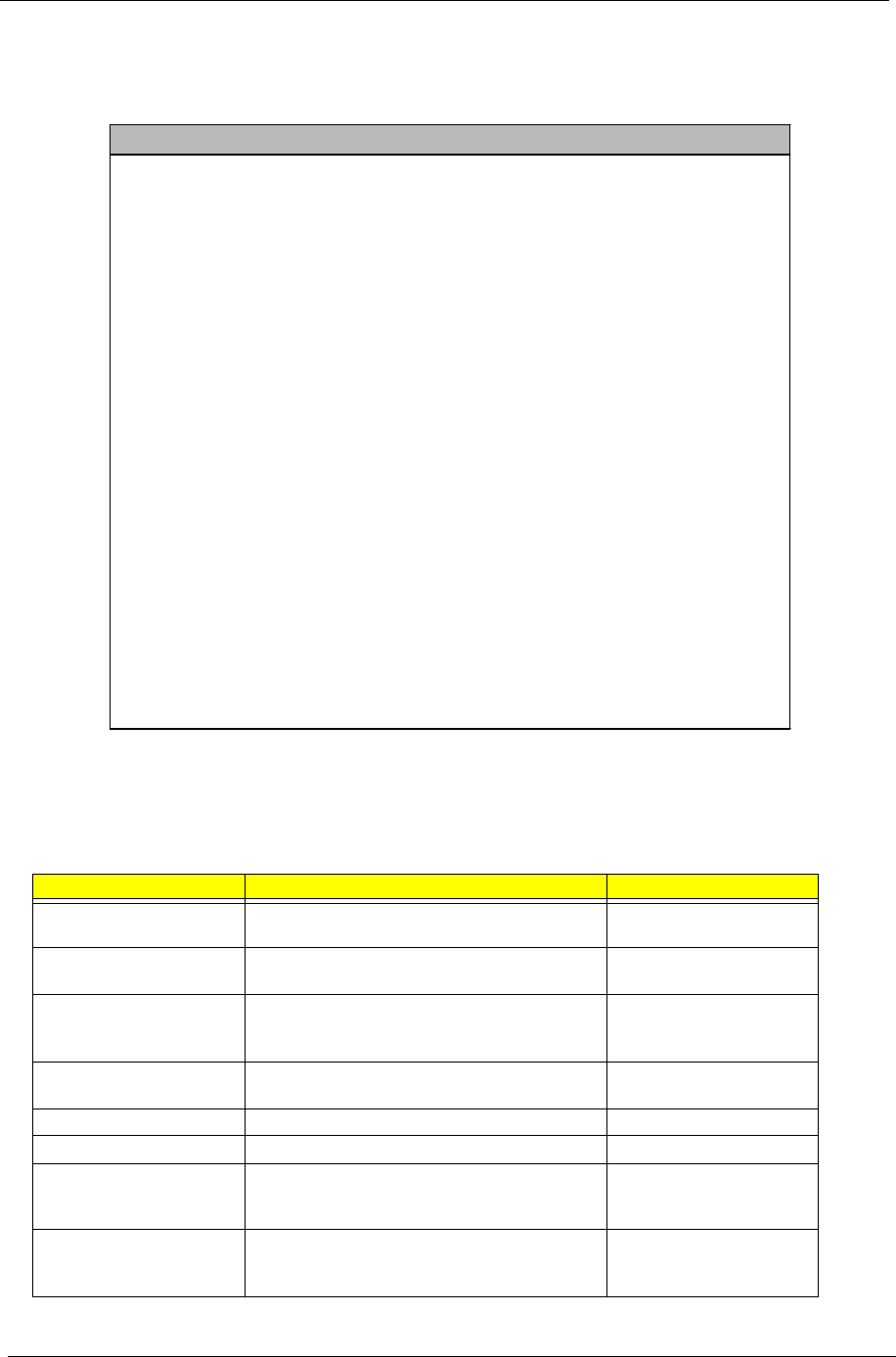
System Information
The following screen appears if you select System Information from the main menu.
This page shows the current basic configuration of your system.
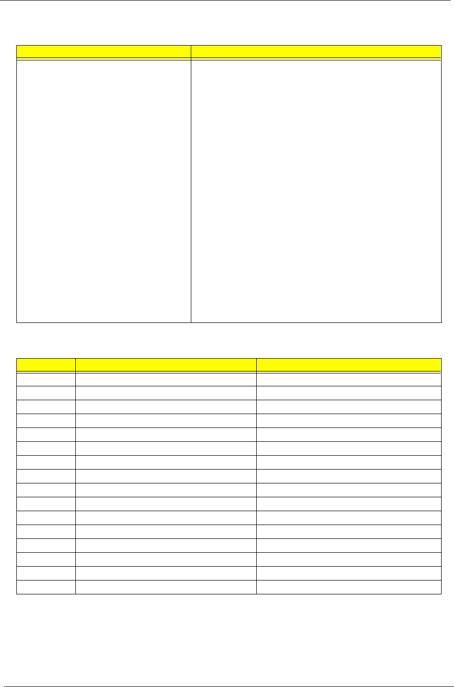
The following table describes the parameters found in the System Information pages:
Parameter Description Format
Processor Specifies the type of processor currently installed
in your system.
Processor Speed Specifies the speed of the processor currently
installed in your system.
Level 1 Cache Specifies the first-level or the internal memory
(i.e., the memory integrated into the processor)
size, and whether it is enabled or disabled.
Cache size in KB
Level 2 Cache Specifies the second-level cache memory size
currently supported by the system.
Cache size in KB
Diskette Drive A Shows the diskette drive A type. Capacity, dimension
Diskette Drive B Shows the diskette drive B type. Capacity, dimension
IDE Primary Channel Master Specifies the current configuration of the IDE
device connected to the master port of the primary
IDE channel.
Drive type, capacity
IDE Primary Channel Slave Specifies the current configuration of the IDE
device connected to the slave port of the primary
IDE channel.
Drive type, capacity
System Information
Processor ........................... Pentium III
Processor Speed ..................... 600 MHz
Level 1 Cache ....................... 32 KB, Enabled
Level 2 Cache ....................... 256 KB, Enabled
Diskette Drive A .................... 1.44 MB 3.5-inch
Diskette Drive B .................... None
IDE Primary Channel Master .......... HardDisk,xxxx M.B.
IDE Primary Channel Slave ........... None
IDE Secondary Channel Master ........ IDE CD-ROM
IDE Secondary Channel Slave ......... None
Total Memory ........................ 64 MB
1st Bank........................... SDRAM, 32 MB
2nd Bank........................... SDRAM, 32 MB
3rd Bank........................... none
Serial Port 1 ....................... 3F8h, IRQ 4
Serial Port 2 ....................... Disabled
Parallel Port ....................... 378h, IRQ 7
PS/2 Mouse .......................... Installed

Chapter 2 31
IDE Secondary Channel
Master
Specifies the current configuration of the IDE
device connected to the master port of the
secondary IDE channel.
Drive type, capacity
IDE Secondary Channel
Slave
Specifies the current configuration of the IDE
device connected to the slave port of the
secondary IDE channel.
Drive type, capacity
Total Memory Specifies the total amount of onboard memory.
The memory size is automatically detected by
BIOS during the POST. If you install additional
memory, the system automatically adjusts this
parameter to display the new memory size.
Memory size in MB
1st Bank Indicates the type of DRAM installed in the DIMM
1 socket. The None setting indicates that there is
no DRAM installed.
DIMM type, capacity in MB
2nd Bank Indicates the type of DRAM installed in the DIMM
2 socket. The None setting indicates that there is
no DRAM installed.
DIMM type, capacity in MB
3rd Bank Indicates the type of DRAM installed in the DIMM
3 socket. The None setting indicates that there is
no DRAM installed.
DIMM type, capacity in MB
Serial Port 1 If enabled, indicates the IRQ and Direct Memory
Address (DMA) assigned to serial port 1.
DMA, IRQ
Serial Port 2 If enabled, indicates the IRQ and Direct Memory
Address (DMA) assigned to serial port 2.
DMA, IRQ
Parallel Port If enabled, indicates the IRQ and Direct Memory
Address (DMA) assigned to the parallel port.
DMA, IRQ
PS/2 Mouse Specifies the presence of a PS/2 mouse Installed or Disabled
Parameter Description Format
32 Chapter 2
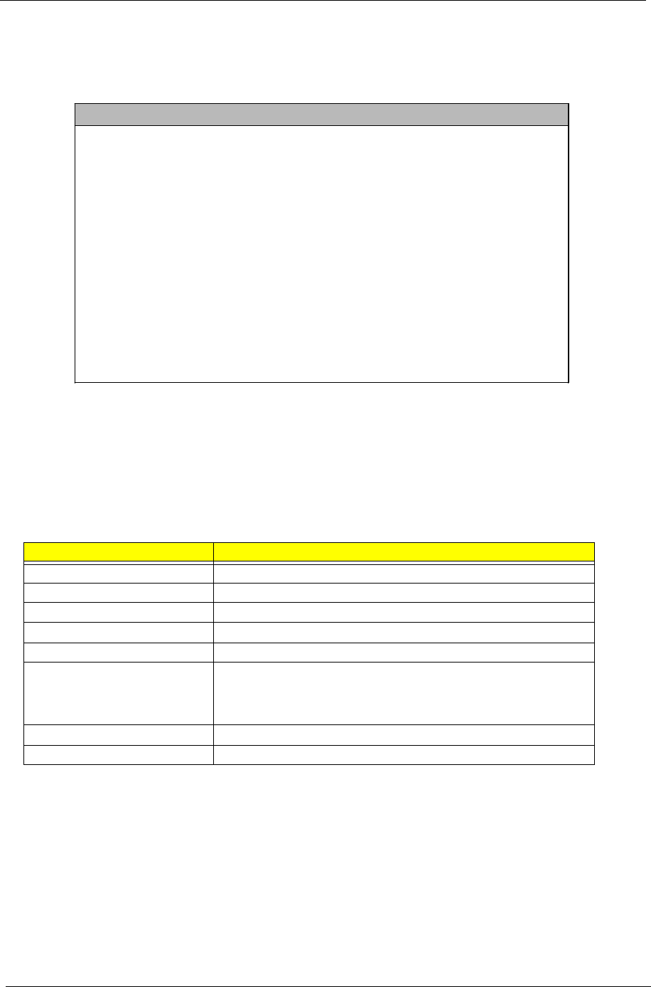
Product Information
The screen below appears if you select Product Information from the main menu:
NOTE: The asterisk (*) mark indicates that the parameter appears only when you are in the Advanced Level.
The Product Information menu contains general data about the system, such as the product name, serial
number, BIOS version, etc. These information is necessary for troubleshooting (maybe required when asking
for technical support).
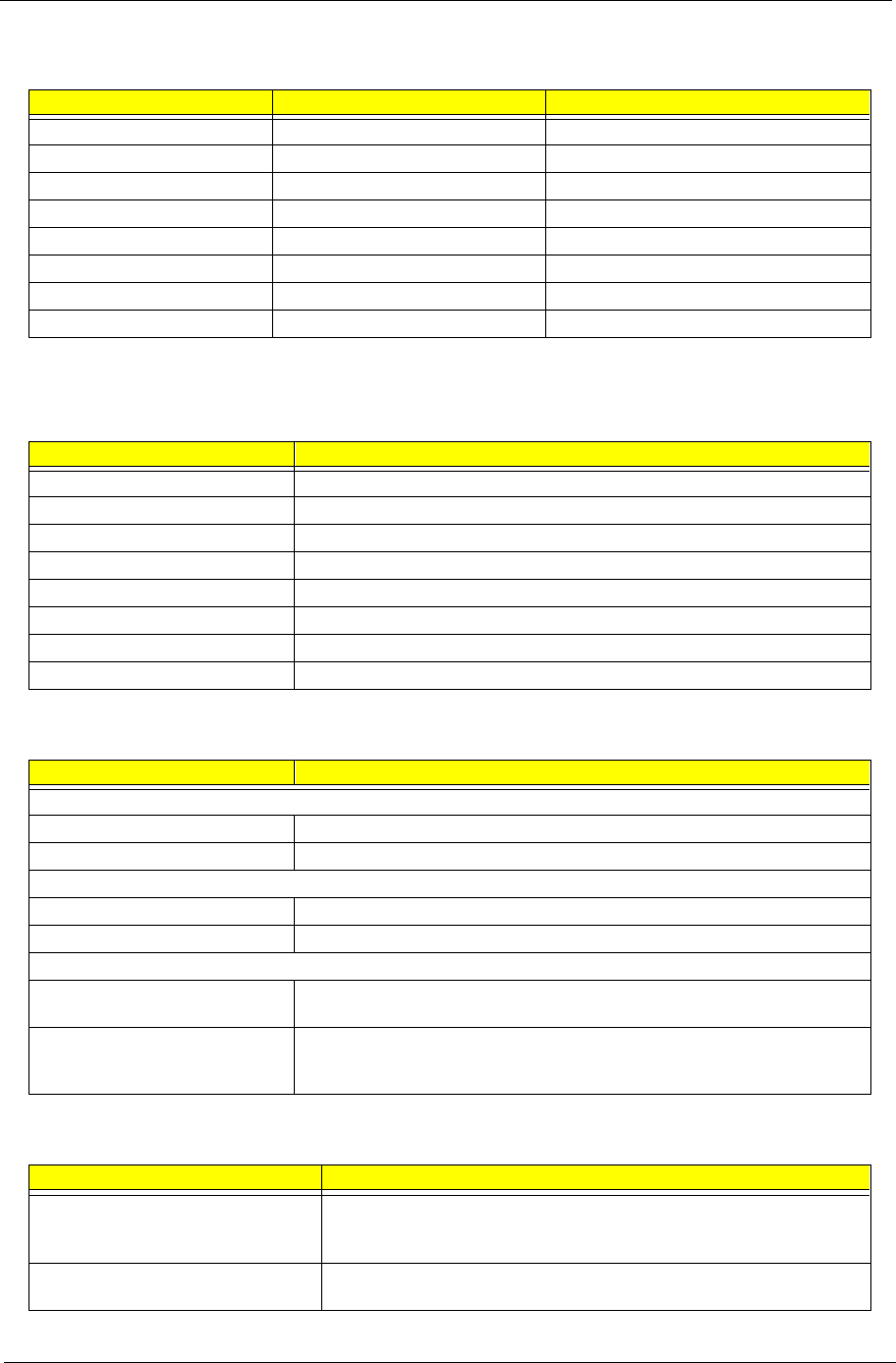
The following table describes the parameters found in this menu:
Parameter Description
Product Name Displays the model name of your system.
System S/N Displays your system’s serial number.
Main Board ID Displays the main board’s identification number.
Main Board S/N Displays your main board’s serial number.
System BIOS Version Specifies the version of your BIOS utility.
SMBIOS version The System Management Interface (SM) BIOS allows you to check your
system hardware components without actually opening your system.
Hardware checking is done via software during start up. This parameter
specifies the version of the SMBIOS utility installed in your system.
System BIOS ID Specifies the version ID of the BIOS utility.
BIOS Release Date Displays the release date of the BIOS utility.
Product Information
Product Name ................... Acer Veriton 5100/7100
System S/N ..................... N/A
Main Board ID .................. S58M
Main Board S/N ................. N/A
System BIOS Version ............ V4.0
SMBIOS Version ................. 2.3
*System BIOS ID.................. R01-A0 EN
*BIOS Release Date............... Jan 03,’00
Chapter 2 33
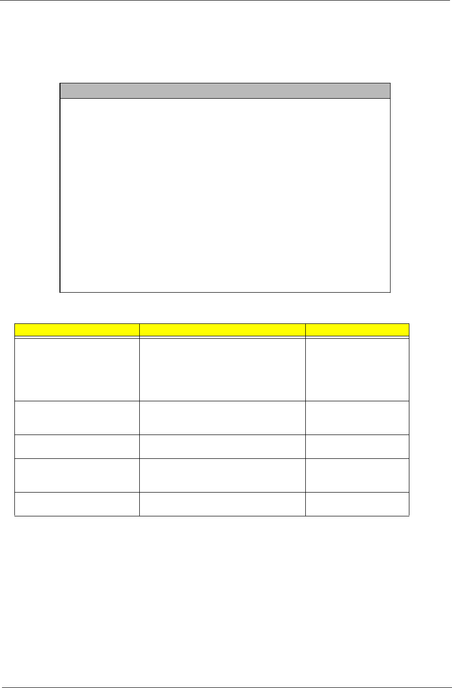
Disk Drives
Select Disk Drives from the main menu to configure the drives installed in your system.
NOTE: The following screen shows the Disk Drives menu:
The asterisk (*) mark indicates that the parameter appears only when you are in the Advanced Level.
The following table describes the parameters found in this menu.
Parameter Description Options
Diskette Drive A / B Allows you to configure your floppy drive None
360 KB, 5.25-inch
1.2 MB, 5.25-inch
720 KB, 3.5-inch
1.44 MB, 3.5-inch
2.88 MB, 3.5-inch
IDE Primary Channel Master Lets you configure the hard disk drive
connected to the master port of IDE channel
1.
IDE Primary Channel Slave Lets you configure the hard disk drive
connected to the slave port of IDE channel 1.
IDE Secondary Channel Master Lets you configure the hard disk drive
connected to the master port of IDE channel
2.
IDE Secondary Channel Slave Lets you configure the hard disk drive
connected to the slave port of IDE channel 2.
Disk Drives
Diskette Drive A .................[1.44 MB 3.5-inch]
Diskette Drive B .................[None]
! * IDE Primary Channel Master
! * IDE Primary Channel Slave
! * IDE Secondary Channel Master
! * IDE Secondary Channel Slave

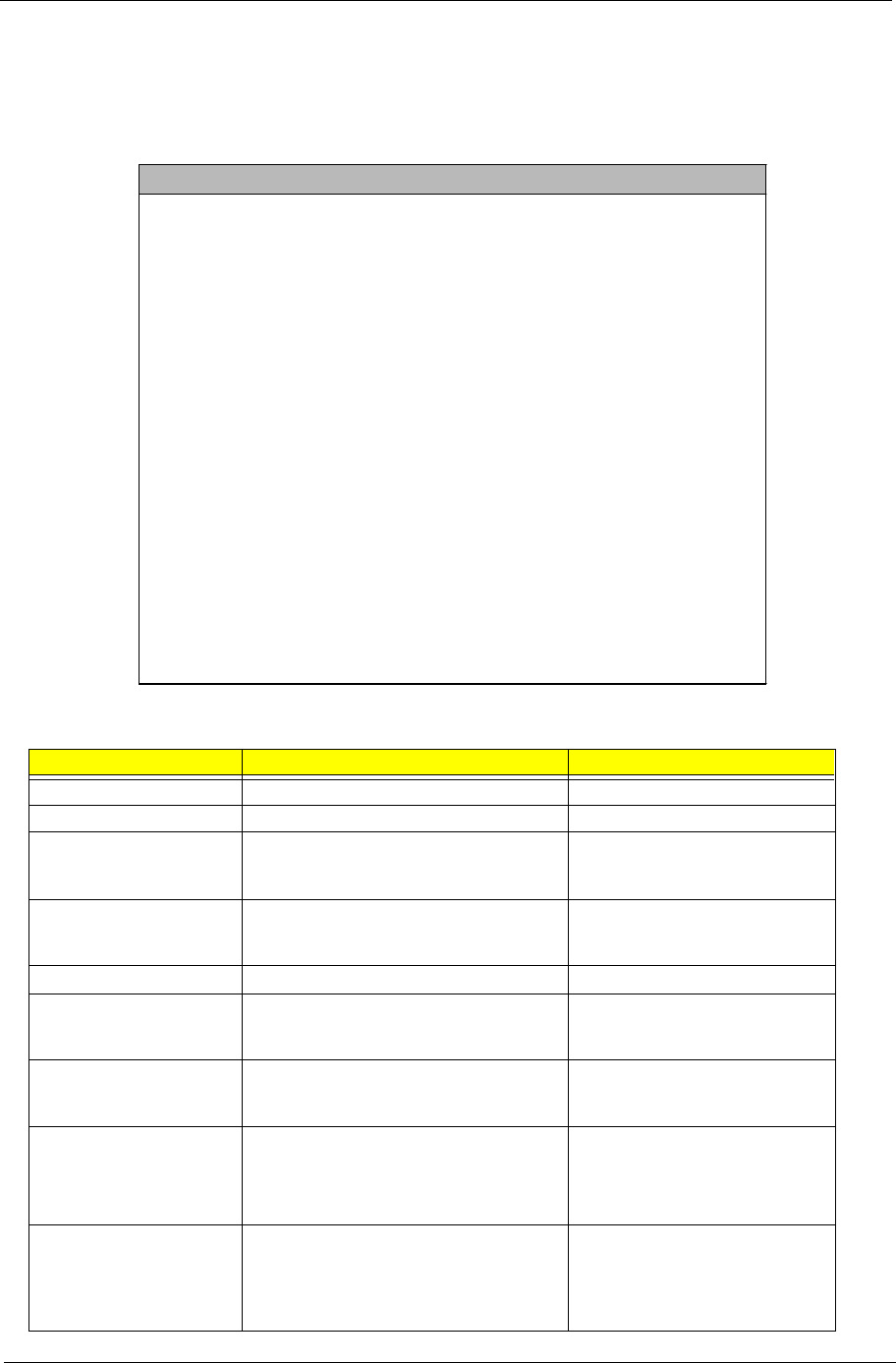
34 Chapter 2
The following screen appears if you select any of the IDE drive parameters:
NOTE: The asterisk (*) mark indicates that the parameter appears only when you are in the Advanced Level.
IDE Primary Channel Master
Device Detection Mode ............... [Auto]
Device Type........................ Hard Disk
Cylinder........................... [8354]
Head............................... [16]
Sector............................. [63]
Size............................... [4311] M.B.
Hard Disk LBA Mode .................. [Auto]
*Hard Disk Block Mode................ [Auto]
*Hard Disk 32 Bit Access............. [Enabled]
*Advanced PIO Mode................... [Enabled]
*DMA Transfer Mode................... [Enabled]
IDE Primary Channel Slave
Device Detection Mode ............... [Auto]
Device Type........................ None
Cylinder........................... [0]
Head............................... [0]
Sector............................. [0]
Size............................... [0] M.B.

Chapter 2 35
NOTE: The asterisk (*) mark indicates that the parameter appears only when you are in the Advanced Level.
The following table describes the parameters found in this menu.
Parameter Description Options
Device Detection Mode Lets you specify the type of hard disk installed in your
system. If you want BIOS to automatically configure
your hard disk, select Auto. If you know your hard
disk type, you can enter the setting manually.
Setting this parameter also sets the Cylinder, Head,
Sector, and Size parameters.
Auto, None, or User. The User
setting allows you to enter your
settings manually if you know
your hard disk type. The Auto
setting also sets the Cylinder,
Head, Sector, and Size
parameters.
Device Type Display the type of device installed. Not configurable. The default
is Hard Disk.
IDE Secondary Channel Master
Device Detection Mode ............... [Auto]
Device Type........................ None
Cylinder........................... [0]
Head............................... [0]
Sector............................. [0]
Size............................... [0] M.B.
IDE Secondary Channel Slave
Device Detection Mode ............... [Auto]
Device Type ........................ IDE CD-ROM
*Advanced PIO Mode ................... [Enabled]
*DMA Transfer Mode ................... [Enabled]

36 Chapter 2
Cylinder Specifies your hard disk’s number of cylinders, and is
automatically set depending on your Type parameter
setting.
Only Device Detection Mode is
set to User, the item Cylinder
will be available; Otherwise it is
non-configurable.
Head Specifies your hard disk’s number of heads, and is
automatically set depending on your Type parameter
setting.
Only Device Detection Mode is
set to User, the item Head will
be available; Otherwise it is
non-configurable.
Sector Specifies your hard disk’s number of sectors, and is
automatically set depending on your Type parameter
setting.
Only Device Detection Mode is
set to User, the item Sector will
be available; Otherwise it is
non-configurable.
Size Specifies the size of your hard disk, in MB, and is
automatically set depending on your Type parameter
setting
It will turn to gray and will be
non- configurable.
Hard Disk LBA Mode Set to “Auto” under DOS and Windows. Set to
“Disabled” under Novell Netware and Unix. Auto or Disabled
Hard Disk Block Mode This function enhances disk performance depending
on the hard disk in use. If you set this parameter to
Auto, the BIOS utility automatically detects if the
installed hard disk drive supports the Block Mode
function. If supported, it allows data transfer in blocks
(multiple sectors) at a rate of 256 bytes per cycle.
Auto or Disabled
Hard Disk 32-bit Access Enabling this parameter improves system
performance by allowing the use of the 32-bit hard
disk access. This enhanced IDE feature works only
under DOS, Windows 3.x, Windows 95/98, Windows
NT, and Novell NetWare.
Enabled or Disabled
Advanced PIO Mode When set to Auto, the BIOS utility automatically
detects if the installed hard disk supports the function,
it allows for faster data recovery and read/ write
timing that reduces hard disk activity time. This
results in better hard disk performance.
Auto, Mode 0, 1, 2, 3 or 4
DMA Transfer Mode The Ultra DMA and Multi-DMA modes enhance hard
disk performance by increasing the transfer rate.
However, besides enabling these features in the
BIOS Setup, both the Ultra DMA and Multi-DMA
modes require the DMA driver to be loaded.
Auto
Multiword Mode 0, 1, 2
Ultra Mode 0, 1, 2, 3, 4
Disabled
Parameter Description Options
Chapter 2 37
Onboard Peripherals
The Onboard Peripherals menu allows you to configure the onboard devices. Selecting this option from the
main menu displays the following screen:
The following table describes the parameters found in this menu.
Parameter Description Options
Serial Port 1 Lets you enable or disable the serial port 1. Enabled or Disabled
Serial Port 2 Lets you enable or disable the serial port 2. Disabled or Enabled
Base Address Lets you set a logical base address for each
serial port. This parameter is configurable
only if the Serial Port parameter is enabled.
3F8h (for serial port 1), 2F8h (for
serial port 2), 3E8h, 2E8h
IRQ Lets you assign an interrupt for each serial
port. This parameter is configurable only if
the Serial Port parameter is enabled.
4 or 11(for serial port 1), 3 or 10 (for
serial port 2)
Parallel Port Lets you enable or disable the parallel port. Enabled or Disabled
Base Address Lets you set a logical base address for the
parallel port. This parameter is configurable
only if the Parallel Port parameter is enabled.
3BCh, 378h, 278h
IRQ Lets you assign an interrupt for the parallel
port. This parameter is configurable only if
the Parallel Port parameter is enabled.
7 or 5
Operation Mode Lets you set your parallel port’s operation
mode. This parameter is configurable only if
the Parallel Port parameter is enabled.
Enhanced Parallel Port (EPP)
Bidirectional
Standard Parallel Port (SPP)
Extended Capabilities Port (ECP)
ECP DMA Channel Allows you to assign a DMA channel for the
ECP parallel port function. This parameter is
configurable only if you select the Extended
Capabilities Port (ECP) as the operation
mode.
1 or 3
Onboard Peripherals
Serial Port 1 ....................... [Enabled]
Base Address ....................... [3F8h]
IRQ ................................ [4]
Serial Port 2 ........................ [Disabled]
Base Address ....................... [---]
IRQ ................................ [---]
Parallel Port ....................... [Enabled]
Base Address ....................... [378h]
IRQ ................................ [7]
Operation Mode ..................... [EPP]
ECP DMA Channel .................. [-]
Floppy Disk Controller .............. [Enabled]
IDE Controller ...................... [Both]
PS/2 Mouse Controller ............... [Enabled]
USB Host Controller ................. [Enabled]
USB Legacy Mode .................... [Enabled]
Onboard Audio Chip .................. [Enabled]
Game Port Address ................... [201]
Midi Port Address ................... [330]
Midi Port IRQ ....................... [5]

38 Chapter 2
Floppy Disk Controller Lets you enable or disable the onboard
floppy disk controller. Enabled or Disabled
IDE Controller Lets you enable or disable the onboard
primary, secondary or both IDE interfaces. Both, Primary, or Disabled
PS/2 Mouse Controller Lets you enable or disable the onboard PS/2
mouse controller Enabled or Disabled
USB Host Controller Lets you enable or disable the onboard USB
host controller. Enabled or Disabled
USB Legacy Mode Lets you activate or deactivate the USB
keyboard connected to your system. When
activated, the USB keyboard functions in a
DOS environment.
Enabled or Disabled
Onboard Audio Chip Lets you enable or disable the onboard audio
controller Enabled or Disabled
Game Port Address Sets the I/O base address of the game port. 201, 209, or Disabled
Midi Port Address Sets the I/O base address of the midi port. 330, 300, or Disabled
Midi Port IRQ Sets the IRQ channel of the midi port. 5 or 10
Parameter Description Options

Chapter 2 39
Power Management
The Power Management menu lets you configure the system power-management feature. It works only under
APM mode.
IMPORTANT:If an ACPI-aware operating system such as Windows 98 or Windows 2000 is installed in ACPI
mode, the operating system will use the ACPI interfaces. Then the settings in Power Management
page is non-effective.
The following screen shows the Power Management parameters and their default settings:
The following table describes the parameters found in this menu.
Parameter Description Options
Power Management Mode Allows you to reduce the system’s power
consumption. When enabled, the IDE hard
disk and system timers become
configurable.
Enabled or Disabled
IDE Hard Disk Standby Timer Allows the hard disk to enter Standby mode
after inactivity of 1 to 15 minutes, depending
on your setting.
Off or 1 to 15 minutes
System Sleep Timer Automatically puts the system to power-
saving mode after a specified period of
inactivity. Any keyboard or mouse action, or
any activity detected from the IRQ channels
resumes system operation.
Off, or 2, 5, 10, 15, 20, 30, 40,
50...120 minutes
Sleep Mode Lets you specify the power-saving mode
that the system will enter after a specified
period of inactivity. This parameter is
configurable only if the System Sleep Timer
is enabled.
Suspend or Standby
Power Management
Power Management Mode ............... [Enabled]
IDE Hard Disk Standby Timer ........ [OFF]
System Sleep Timer ................. [OFF]
Sleep Mode ....................... [-------]
Power Switch < 4 sec ................ [Suspend]
System wake-up event
Modem Ring Indicator ............... [Disabled]
PCI Power Management ............... [Enabled]
RTC Alarm ......................... [Disabled]
Resume Day .......................[--]
Resume Time ......................[--:--:--]
Restart on AC/Power Failure ....... [Disabled]
ACPI Sleep State ................... [S1]

40 Chapter 2
Power Switch < 4 sec. Lets you specify whether to automatically
turn off the machine or put the system to
Suspend mode when the power switch is
pressed for less than 4 seconds.
Suspend or Power Off
System Wake-up Event Lets you specify the activity that will resume
the system to normal operation.
Modem Ring Indicator Wakes the system from Sleep mode once
any fax/modem activity is detected. Disabled or Enabled
PCI Power Management Allows the system to be awaken by the PME
function. Enabled or Disabled
RTC Alarm Allows you to set a certain time on a certain
day to wake-up your system from suspend
mode.
Disabled or Enabled
Resume Day If RTC alarm is enabled, the system will
resume operation at the time indicated here.
User Input
Resume Time If RTC alarm is enabled, the system will
resume operation at the time indicated here.
User Input
Restart on AC/ Power Failure When power failure occurs, your system
automatically stops functioning. Setting this
parameter to Enabled lets you set your
computer to automatically turn on once
power resumes. The Disabled setting
leaves the computer off.
Disabled or Enabled
ACPI Sleep State When set to S1, system enters standby
mode when power management mode is
enabled. When set to S3, system enters
suspend to RAM mode.
S1 or S3
Parameter Description Options

Chapter 2 41
Boot Options
This option allows you to specify your preferred settings for bootup.
The following screen appears if you select Boot Options from the main menu:
NOTE: The asterisk (*) mark indicates that the parameter appears only when you are in the Advanced Level.
The following table describes the parameters found in this menu.
Parameter Description Options
Boot Sequence Allows you to specify the boot search sequence. Floppy Disk
Hard Disk
IDE CD-ROM
Intel (R) Boot Agent Version
3.0 ( boot from LAN)
Primary Display Adapter Lets you activate the onboard video controller as
your primary adapter, or automatically disable it
once BIOS detects that there is a video card
installed in your system.
Auto or Onboard
Fast Boot Allows you to define your system’s booting
process, whether to skip some POST routines or
proceed with the normal booting process.
Auto or Disabled
Silent Boot When enabled, BIOS is in graphical mode and
displays only an identification logo during POST
and while booting. Then, the screen displays the
operating system prompt (as in DOS) or logo (as
in Windows). If any error occurs while booting,
the system automatically switches to the text
mode.
You may also switch to the text mode while
booting by pressing F9 after you hear a beep that
indicates the activation of the keyboard.
Enabled or Disabled
Boot Options
Boot Sequence
1st. [Floppy Disk A:]
2nd. [Hard Disk C:]
3rd. [IDE CD-ROM]
4th. [Intel ® Boot Agent Version 3.0]
Primary Display Adapter.............. [Auto]
Fast Boot ........................... [Auto]
Silent Boot ......................... [Enabled]
Num Lock After BOOT ................. [Enabled]
Memory Test ......................... [Disabled]
*Configuration Table ................. [Enabled]
Update BIOS with Boot Block ......... [Disabled]
*Language Type ....................... [English]

42 Chapter 2
Num Lock After Boot Allows you to activate or deactivate the Num
Lock function upon booting. Enabled or Disabled
Memory Test Lets you specify whether you want BIOS to
perform or bypass the memory test. This
parameter is only available when Fast Boot is
disabled.
Disabled or Enabled
Configuration Table This parameter allows you to enable or disable
the display of the configuration table after POST
but before booting. The configuration table gives
a summary of the hardware devices and settings
that BIOS detected during POST.
Enabled or Disabled
Update BIOS w/ Boot Block When enabled, it automatically flashed the BIOS
file from the hard disk drive in case the system
fails to boot up.
Disabled or Enabled
Language Type Select the language. English or Japanese
Parameter Description Options

Chapter 2 43
Date and Time
The following screen appears if you select the Date and Time option from the main menu:
The following table describes the parameters found in this menu:
Parameter Description Options
Date Lets you set the date following the weekday-
month-day-year format.
Weekday: Sun, Mon, Tue, Wed, Thu,
Fri, Sat
Month: Jan, Feb...Dec
Day: 1 to 31
Year: 1980 to 2099
Time Lets you set the time following the hour-
minute-second format.
Hour: 0 to 23
Minute: 0 to 59
Second: 0 to 59
Date and Time
Date .................................. [Mon Jan 03, 2000]
Time .................................. [HH:MM:SS]
44 Chapter 2
System Security
The Setup program has a number of security features to prevent unauthorized access to the system and its
data.
The following screen appears if you select System Security from the main menu:
The following table describes the parameters found in this menu.
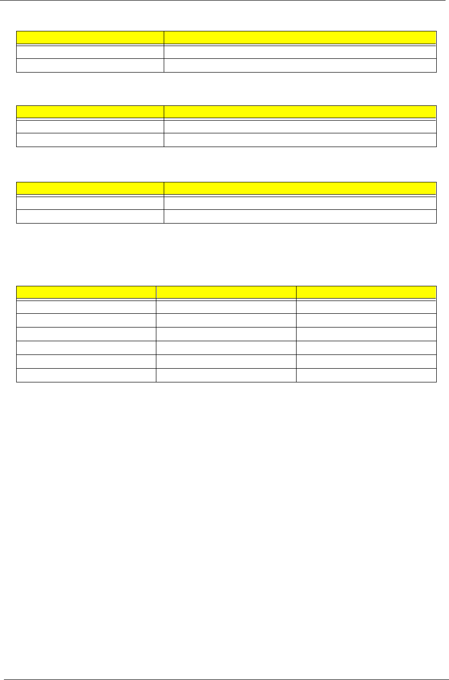
Parameter Description Options
Supervisor Password Prevents unauthorized access to the BIOS
utility.
None or Present. The Present
setting allows you to set a Setup
password. For instructions on how
to set a Setup password, refer to
“Setting a Password” on page 45.
User Password Secures your system against unauthorized
use. Once you set this password, you have
to type it whenever you boot the system.
Disk Drive Controller Allows you to protect your system’s floppy
drive and hard disk data from being modified
(possible under DOS mode only).
Floppy Drive Protects your floppy drive data from being
modified. Normal, Write Protect All Sectors,
Write Protect Boot Sectors
Hard Disk Drive Protects your hard disk data from being
modified. Normal, Write Protect All Sectors,
Write Protect Boot Sectors
Processor Serial Number
System Security
Supervisor Password ................. [None]
User Password ....................... [----]
Disk Drive Controller
Floppy Drive ....................... [Normal]
Hard Disk Drive .................... [Normal]
Processor Serial Number ............. [Disabled]

Chapter 2 45
Setting a Password
3. Enter the BIOS utility and select “System Security” .
4. Highlight the “Supervisor Password” parameter to set a Setup password, or “User Password” to set a
power-on password. Then press the left or right arrow key. The following creen appears:
5. Type a password. The password may consist of up to seven characters. Then press Enter.
6. Retype the password then press Enter.
7. After setting the password, highlight the “Set or Change Password” option.
8. Press Esc to return to the System Security screen. If you have set a Supervisor password (and/or User
password), the Supervisor Password (and/or User password) setting automatically changes to Present.
9. Press Esc to return to the Main menu.
10. Press Esc to exit the BIOS utility. A dialog box appears asking if you want to save the CMOS data.
11. Select “Yes” to save the changes and reboot the system.
If you have set a Supervisor password, the next time you want to enter the BIOS utility, you must key-in your
Supervisor password.
If you have set a User password, you will be prompted to enter that password every time you boot your
system.
Supervisor Password
Enter your Password twice. The Password
may be up to 7 characters long.
Enter Password ...................... [!!!!!!!]
Enter Password again ................ [!!!!!!!]
Set or Change Password

46 Chapter 2
Changing or Removing the Password
If you want to change one of your passwords, do the following:
1. Enter the BIOS utility and select “System Security”.
2. Highlight the “Supervisor Password” parameter (for Supervisor password) or the “User Password”
parameter (a Supervisor Password must be set first before you can change the User password). The
Password menu appears.
3. From the Password menu, highlight the “Set or Change Password” option.
4. Enter a new password.
5. Press Esc to return to the System Security screen.
6. Press Esc to return to the main menu.
7. Press Esc to exit the BIOS utility. A dialog box appears asking if you want to save the CMOS data.
8. Select “Yes” to save the changes.
To remove the password, simply select the “Supervisor Password” parameter (for Supervisor password) or
the “User Password” parameter (a Supervisor Password must be set first before you can change the User
password) from the System Security menu and set it to “None”.
Bypassing the Password
If you forgot your password, you can bypass the password security feature thru hardware configuration.
RTC Battery
Follow these steps to bypass the password:
1. Turn off and unplug the system.
2. Open the system housing. Take off battery and short it.
3. Place on RTC battery, reboot the system and enter setup menu, to load default setting.
Clear CMOS
Follow these steps to bypass the password:
1. Reset CMOS, by adjusting JPX1 to 1-2
2. Reboot the system.
3. Adjust the JPX1 back to 2-3
Password Check
Follow the step to bypass the password:
1. Adjust JPXB to 2-3

Chapter 2 47
Advanced Options
NOTE: The Advanced Options menu is only available if you press F8 or Alt + F4 in the main menu.
The “Advanced Options” menu allows you to configure the system memory and PCI device settings.
The following screen shows the Advanced Options parameters:
CAUTION: Do not change any settings in the Advanced Options menu if you are not a qualified technician to
avoid damaging the system.
Memory/Cache Options
Selecting “Memory/Cache Options” from the Advanced Options menu displays the following screen:
This menu lets you configure the system memory.
The following table describes the parameters found in this sub-menu.
Parameter Description Options
Level 1 Cache (processor
Cache)
Lets you enable or disable the primary cache
memory, i.e., the processor memory. Enabled or Disabled
Level 2 Cache Lets you enable or disable the secondary
cache memory. Enabled or Disabled
Advanced Options
! Memory/Cache Options
! PnP/PCI Options
Memory/Cache Options
Level 1 Cache ....................... [Enabled]
Level 2 Cache ....................... [Enabled]
Memory at 15MB-16MB Reserved for .... [System]
CPU frequency Multiplier .............[3X]

48 Chapter 2
Memory at 15MB-16MB
Reserved for
To prevent memory address conflicts between
the system and expansion boards, reserve
this memory range for the use of either the
system or an expansion board. Some VGA
cards have required settings for this feature.
Check your VGA card manual before setting
this parameter.
System or Expansion board
CPU Frequency Multiplier Sets the Core/bus ratio of your system. The
clock speed of the bus does not necessarily
equal the CPU’s (core). The bus clock speed
is often slower than the CPU clock speed.
3X, 3.5X, 4X, 4.5X.......8X
Parameter Description Options

Chapter 2 49
PnP/PCI Options
The PnP/PCI Options menu allows you to specify the settings for your PCI devices. Selecting this option
displays the following screen:
The following table describes the parameters found in this sub-menu.
Parameter Description Options
PCI IRQ Setting Select Auto to let BIOS automatically configure the plug-
and-play (PnP) devices installed in your system.
Otherwise, select Manual.
Note: Refer to your PCI card manual for technical
information.
Auto or Manual
PCI Slot 1 When you set the PCI IRQ Setting parameter to Auto,
these parameters specify the auto-assigned interrupt for
each of the PCI devices. If you set the PCI IRQ Setting
parameter to Manual, you need to specify the interrupt
that you want to assign for each PCI device installed in
your system.
User input
PCI IRQ Sharing Setting this parameter to Yes allows you to assign the
same IRQ to two different devices. To disable the
feature, select No.
Note: If there are no IRQs available to assign for the
remaining device function, we recommend that you
enable this parameter.
Yes or No
VGA Palette Snoop This parameter permits you to use the palette snooping
feature if you installed more than one VGA card in the
system. The VGA palette snoop function allows the
control palette register (CPR) to manage and update the
VGA RAMDAC (Digital Analog Converter, a color data
storage) of each VGA card installed in the system. The
snooping process lets the CPR send a signal to all the
VGA cards so that they can update their individual
RAMDACs. The signal goes through the cards
continuously until all RAMDAC data has been updated.
This allows the display of multiple images on the screen.
Note: Some VGA cards have required settings for this
feature. Check your VGA card manual before setting this
parameter.
Disabled or Enabled
PnP/PCI Options
PCI IRQ Setting ..................... [Auto]
INTA INTB INTC INTD
PCI Slot 1 ............. [--] [--] [--] [--]
PCI Slot 2 ............. [--] [--] [--] [--]
PCI Slot 3 ............. [--] [--] [--] [--]
PCI IRQ Sharing ...................... [Yes]
VGA Palette Snoop ................... [Disabled]
Graphics Aperture Size .............. [64] MB
Plug and Play OS .................... [Yes]
Reset Resource Assignments .......... [No]

50 Chapter 2
Chipset Settings
The Chipset Settings will be shown only if you press Alt + F4 in main menu:
Press Enter to view the Chipset settings information.
Graphics Aperture Size This parameter determines the effective size of the
graphics aperture. Graphics aperture is the address
range that the AGP video and the CPU use to manage
graphical objects. The lowest setting is 8 MB and the
highest is 256 MB.
User input
Plug and Play OS When this parameter is set to Yes, BIOS initializes only
PnP boot devices such as SCSI cards. When set to No,
BIOS initializes all PnP boot and non-boot devices such
as sound cards.
Note: Set this parameter to Yes only if your operating
system is Windows 95/98/2000.
Yes or No
Reset Resource
Assignments
Set this parameter to Yes to avoid IRQ conflict when
installing non-PnP or PnP ISA cards. This clears all
resource assignments and allows BIOS to reassign
resources to all installed PnP devices the next time the
system boots. After clearing the resource data, the
parameter resets to No.
No or Yes
Parameter Description Options
Advanced Options
! Memory/Cache Options
! PnP/PCI Options
! *Chipset Settings
Chapter 2 51
The following screen displays the Chipset settings menu:
Parameter Description Options
Spread Spectrum This parameter lets you enable or disable the
spread spectrum. Enabled or Disabled
ICH Audio Codec This parameter lets you enable or disable the
ICH Audio Codec. Enabled or Disabled
ICH SMBUS Controller This parameter lets you enable or disable the
ICH SMBUS controller. Enabled or Disabled
Delay Transaction This parameter lets you enable or disable delay
transaction. Enabled or Disabled
Determine DIMM Frequency This parameter lets you set the frequency of
DIMM. Auto, PC100 or PC133
Chipset Settings
• Spread Spectrum ............... [Enabled]
• ICH Audio Codec ............... [Enabled]
• ICH SMBUS Controller .......... [Enabled]
• Delay Transaction ............. [Enabled]
• Determine DIMM Frequency ...... [Auto]

52 Chapter 2
Load Default Settings
You need to reload the BIOS default settings every time you make changes to your system hardware
configuration (such as memory size, CPU type, hard disk type, etc.); otherwise, BIOS will keep the previous
CMOS settings. Selecting this option displays the following dialog box:
Choosing Yes enables BIOS to automatically detect the hardware changes that you have made in your
system. This option also allows you to restore the default settings.
Choosing No returns you to the main menu without loading the default settings.
Load Default Settings
Do you want to load default settings?
[Yes] *[No]

Chapter 2 53
Abort Settings Change
Selecting the Abort Settings Change option from the main menu displays the following dialog box:
Choosing Yes discards all the changes that you have made and reverts the parameters to their previously
saved settings.
Choosing No returns you to the main menu. BIOS retains all changes that you have made.
Abort Settings Change
Do you really want to abort settings change?
*[Yes] [No]

54 Chapter 2
Exiting Setup
To exit the BIOS utility, simply press Esc. The following dialog box appears:
Select Yes to exit Setup. Select No to return to the main menu.
If you have made changes in the parameter settings, you will be asked if you want to keep the changes made
to the BIOS. Select Yes to save your changes before you exit Setup. Select No to discard all changes and
exit Setup.
Exit Setup
Settings have been changed.
Do you really want to exit setup?
*[Yes] [No]
Exit Setup
Settings have been changed.
Do you want to save CMOS settings?
*[Yes] [No]

Chapter 3 55
This chapter contains 2 separate step-by-step procedures on how to disassemble the Veriton 5100 and 7100
desktop computer for maintenance and troubleshooting.
To disassemble the computer, you need the following tools:
TWrist grounding strap and conductive mat for preventing electrostatic discharge
TFlat-bladed screwdriver
TPhillips screwdriver
THexagonal screwdriver
TPlastic stick
NOTE: The screws for the different components vary in size. During the disassembly process, group the
screws with the corresponding components to avoid mismatches when putting back the components.
Machine Disassembly and Replacement
Chapter 3
56 Chapter 3
Disassembling the Veriton 5100
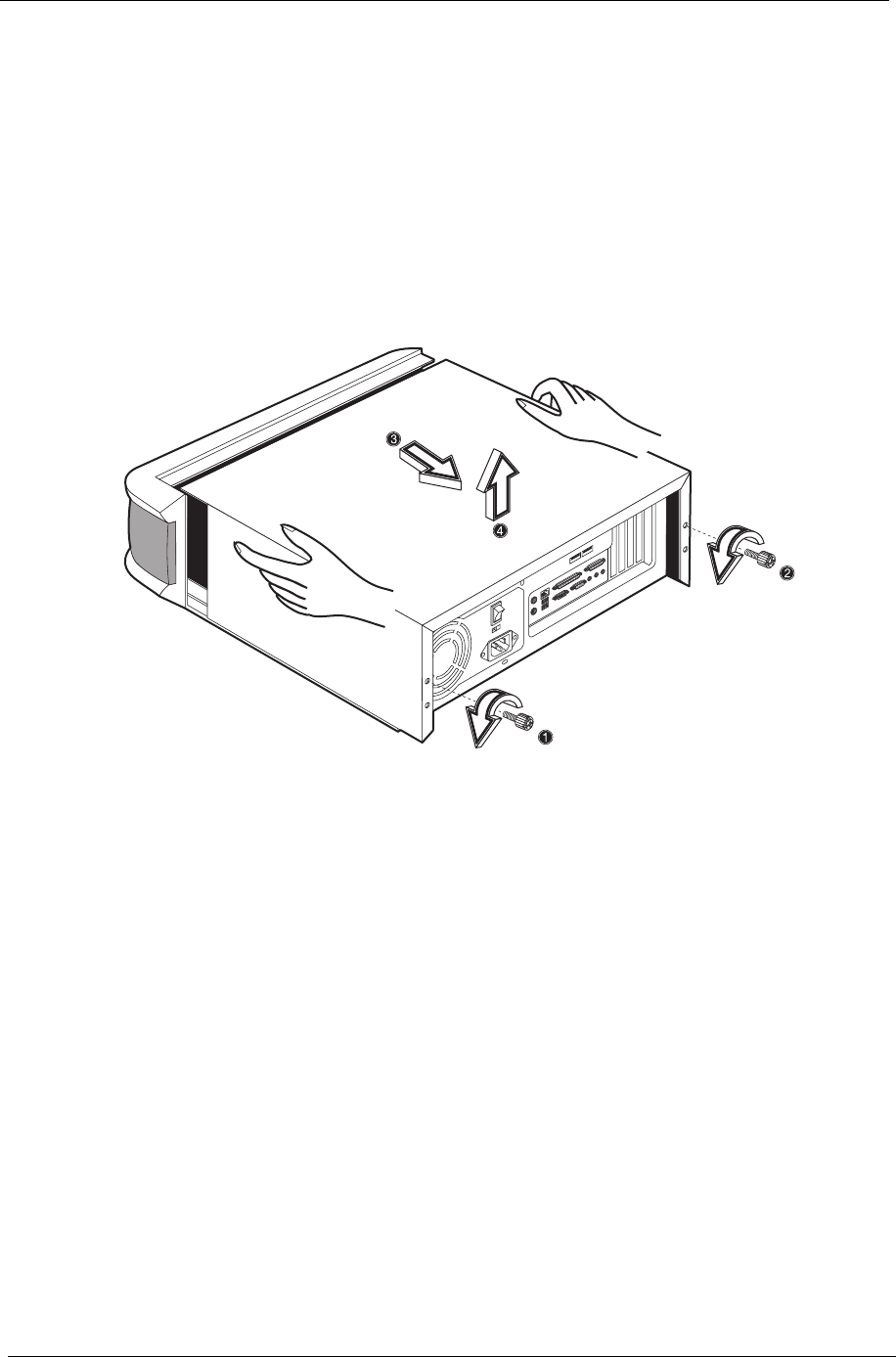
Removing the Housing Cover
CAUTION: Before you proceed, make sure that you have turned off the system and all peripherals connected
to it.
1. Turn off the system power and unplug all cables.
2. Place the system unit on a flat, steady surface.
3. Turn the thumbscrews counterclockwise to remove the cover. Set the screws aside. You will need the
when replacing the housing cover.
4. Hold the sides of the cover with both hands. Slide it back about an inch and then gently pull it outward to
detach it.
Chapter 3 57
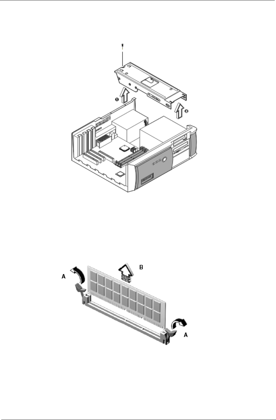
Removing a Link Bar
1. To remove a link bar, remove the screw that secures it to the housing.
2. Then gently lift the link bar and pull it out.
Removing a DIMM
1. Press the latches on both sides of the DIMM socket outward, to release the DIMM.
2. Then gently lift the DIMM out to remove it.
58 Chapter 3
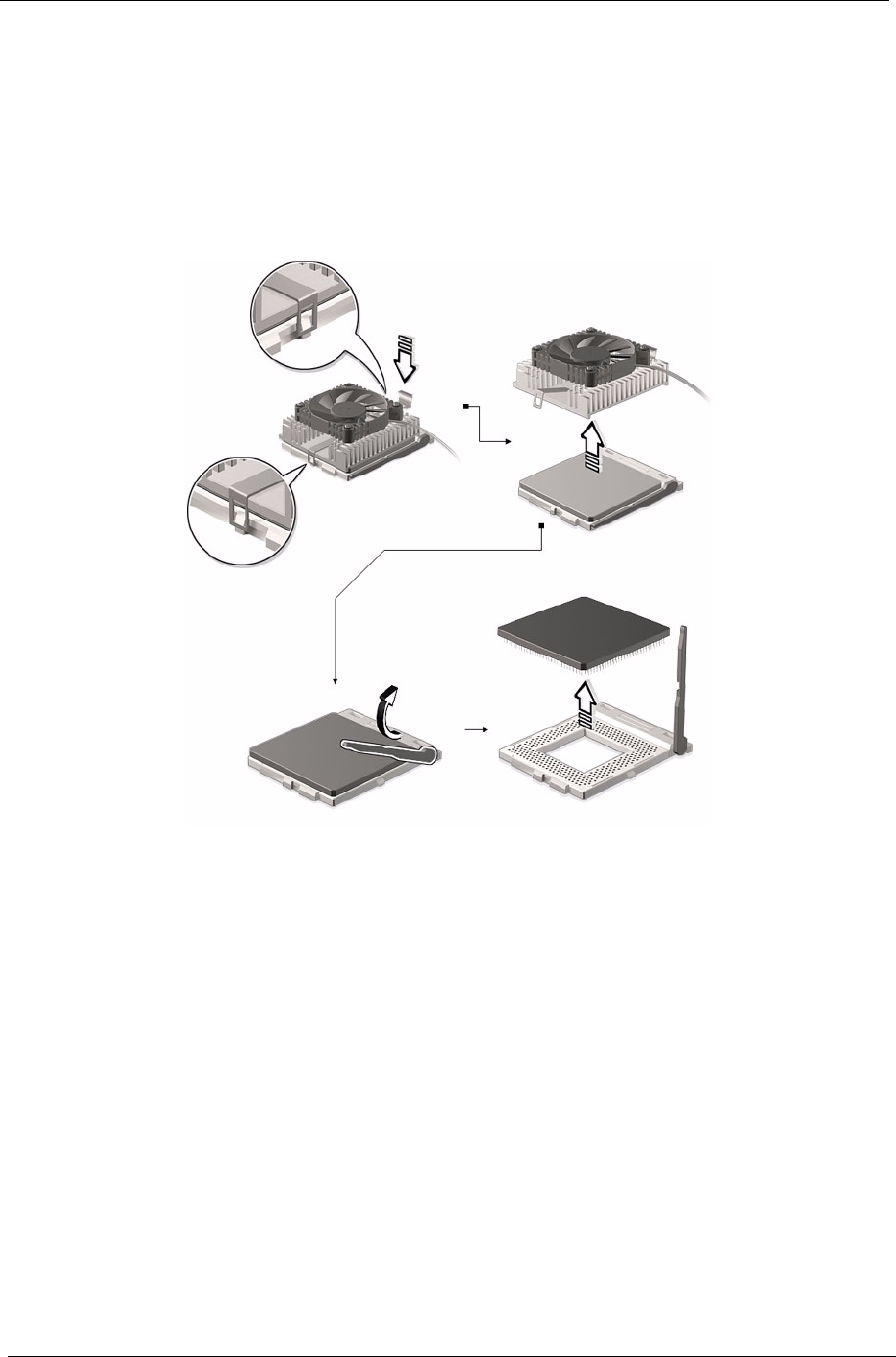
Removing the Processor
Follow these steps to remove the processor:
1. Detach the fan/heatsink cable connector .
2. Remove the fan/heatsink from the processor.
3. Pull the socket lever up to release the processor pins from the socket holes.
4. Pull out the processor from the socket.
.
WARNING:The heatsink becomes very hot when the system is On. Never touch the heatsink with any
metal or with your hands.
Chapter 3 59
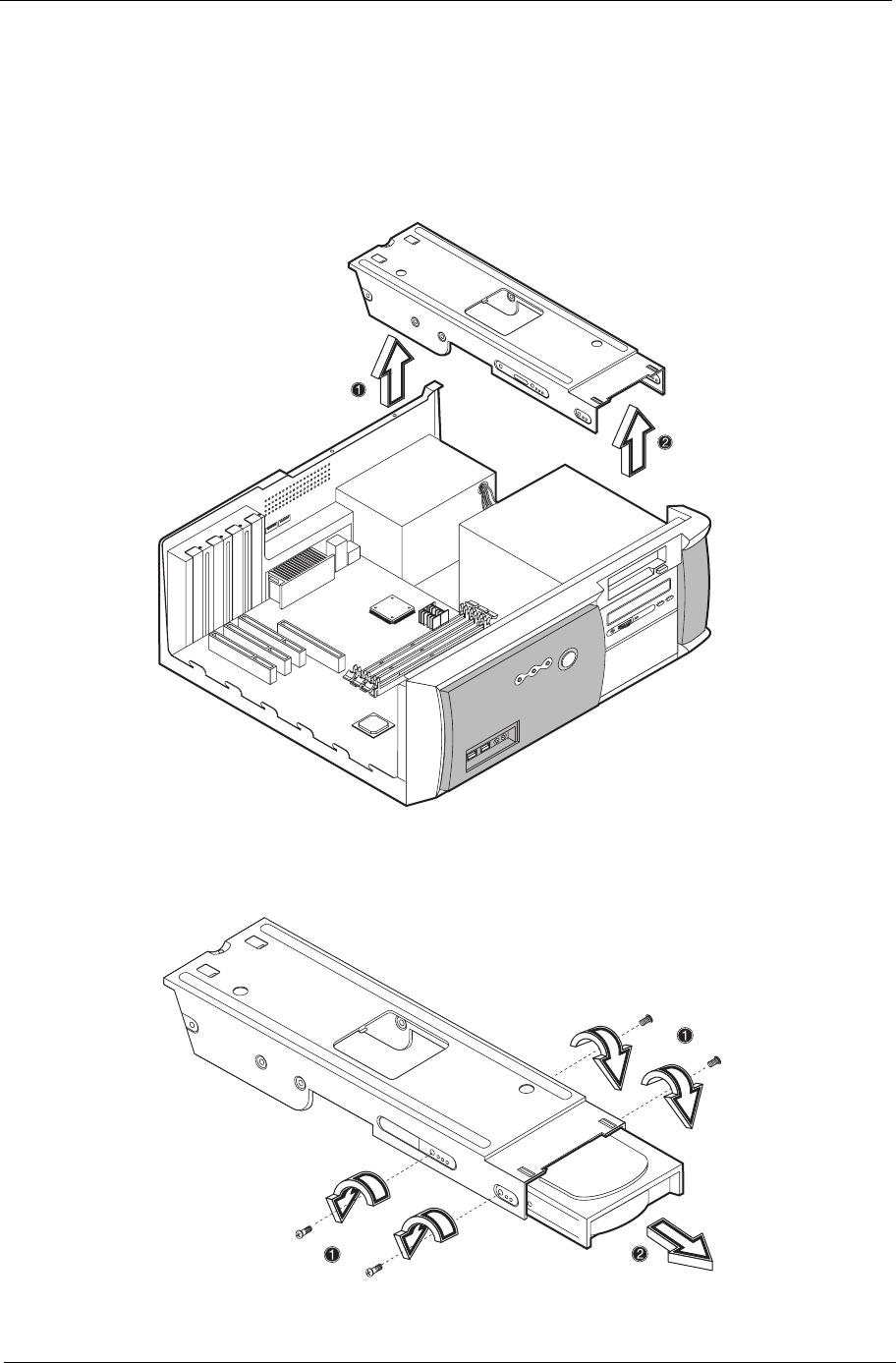
Removing the Hard Disk Drive and 3.5-inch Diskette Drive
Follow these steps to remove the hard disk drive:
1. Detach the power and disk drive cables from the hard disk and diskette drive.
2. Remove the screw that secures the link bar to the housing.
3. Lift up the link bar and pull it out.
4. Remove the four screws that hold the hard disk drive to the disk frame and detach the hard disk drive. Set
the screws aside.
60 Chapter 3
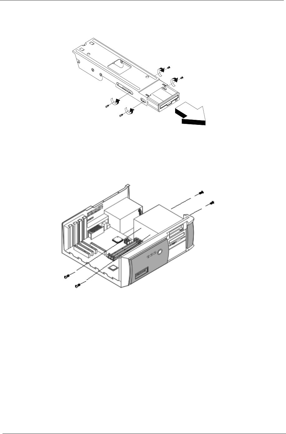
5. Remove the four screws that hold the diskette drive to the disk frame and pull out the diskette drive.
Removing the CD-ROM Drive
1. Remove the four screws that hold the CD-ROM drive to the bracket frame and pull out the CD-ROM drive.
Chapter 3 61
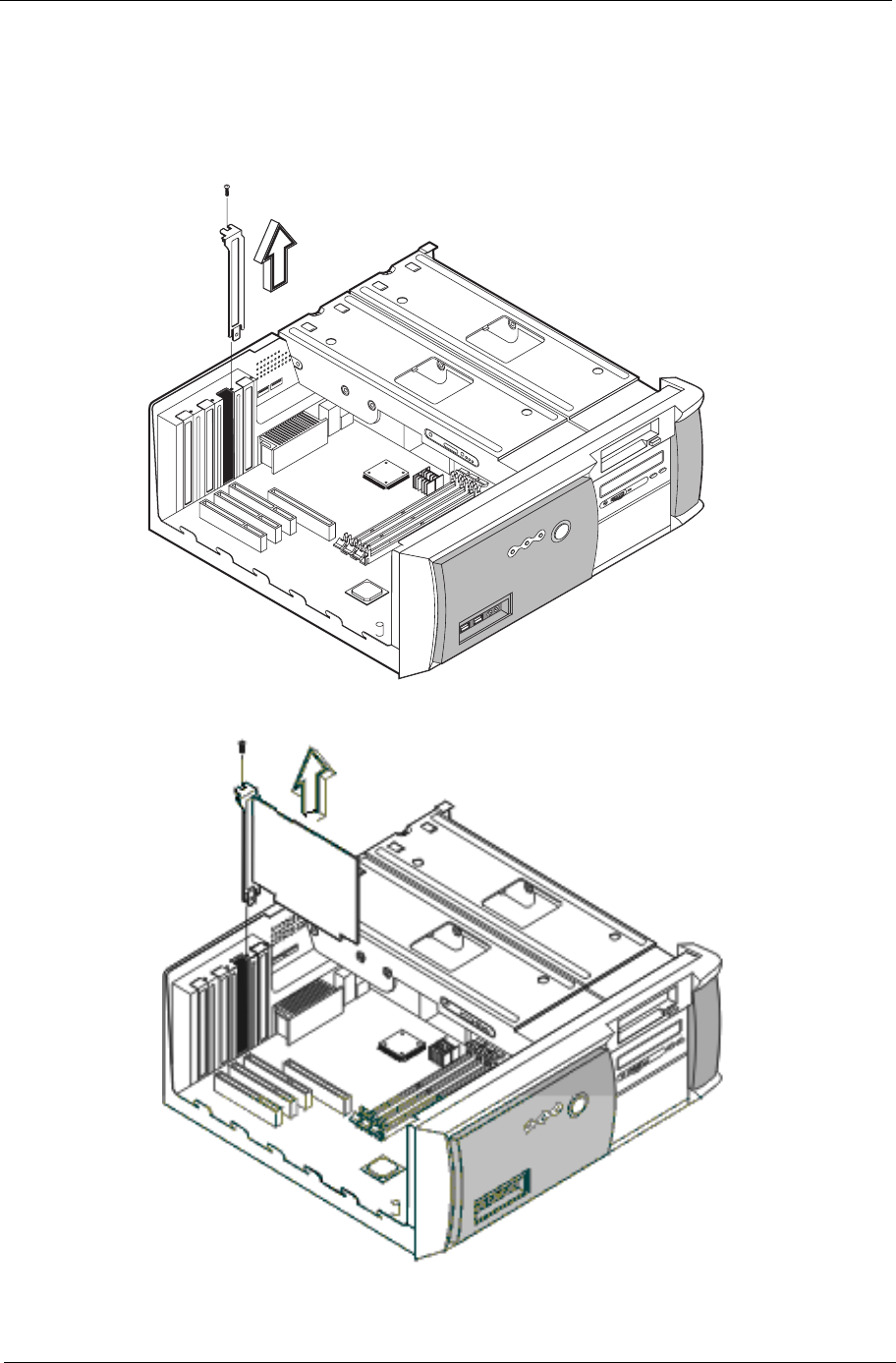
Removing the PCI and AGP Expansion Cards
1. Remove the screw on the bracket of an expansion card. Set the screw aside. You will need it when
replacing the expansion card.
2. Gently pull out the expansion card to remove it from the expansion slot.
NOTE: When you turn on the system, BIOS automatically detects and assigns resources to the PCI devices.
62 Chapter 3
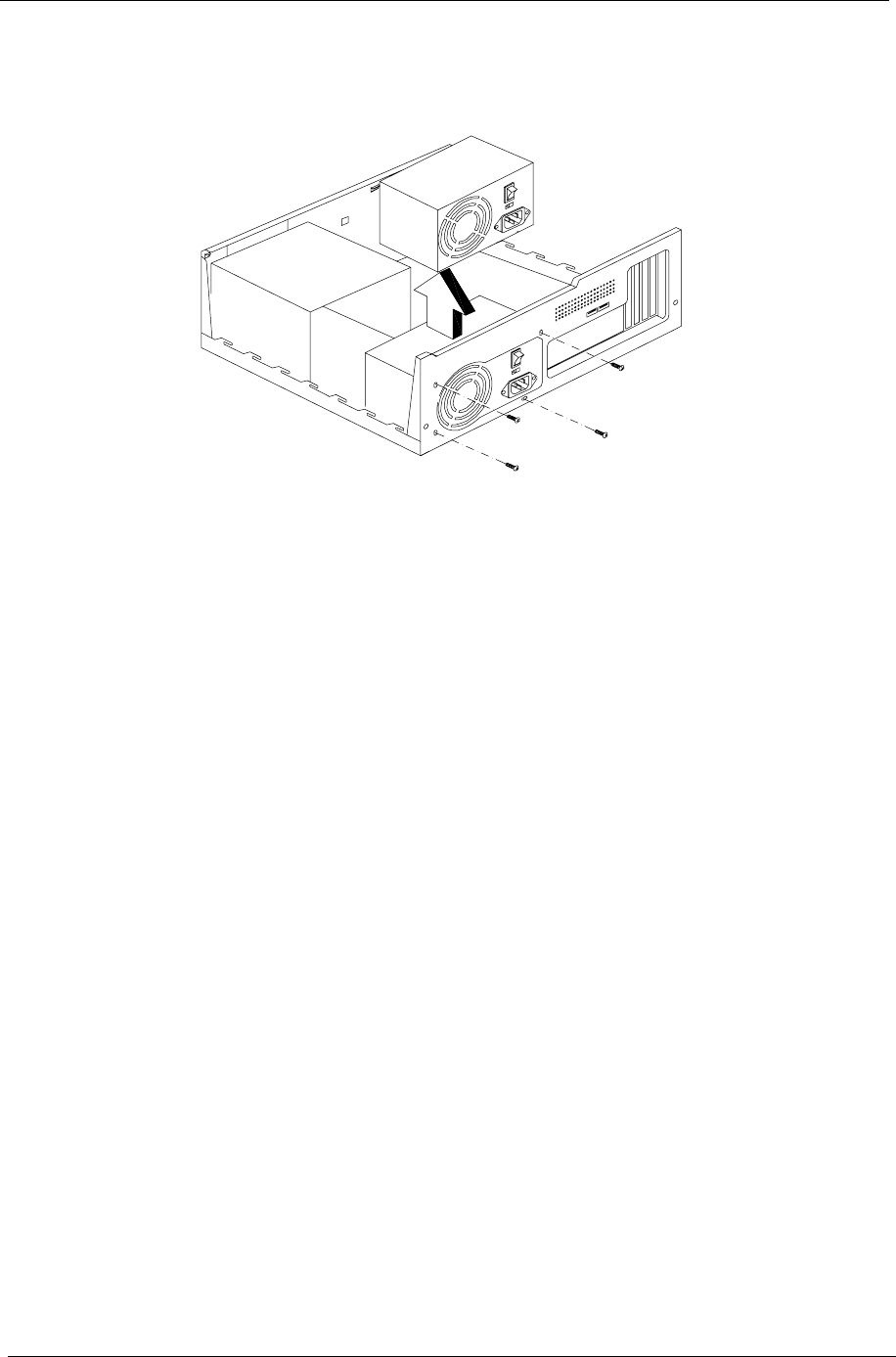
Removing the Power Supply
1. Remove the four screws that hold the power supply to the housing and pull out the power supply.
Chapter 3 63
Disassembling the Veriton 7100
Opening the Housing
This section tells you how to open the housing cover when you need to install additional components inside
the system unit.
CAUTION: Before you proceed, make sure that you have turned off the system and all peripherals connected
to it.
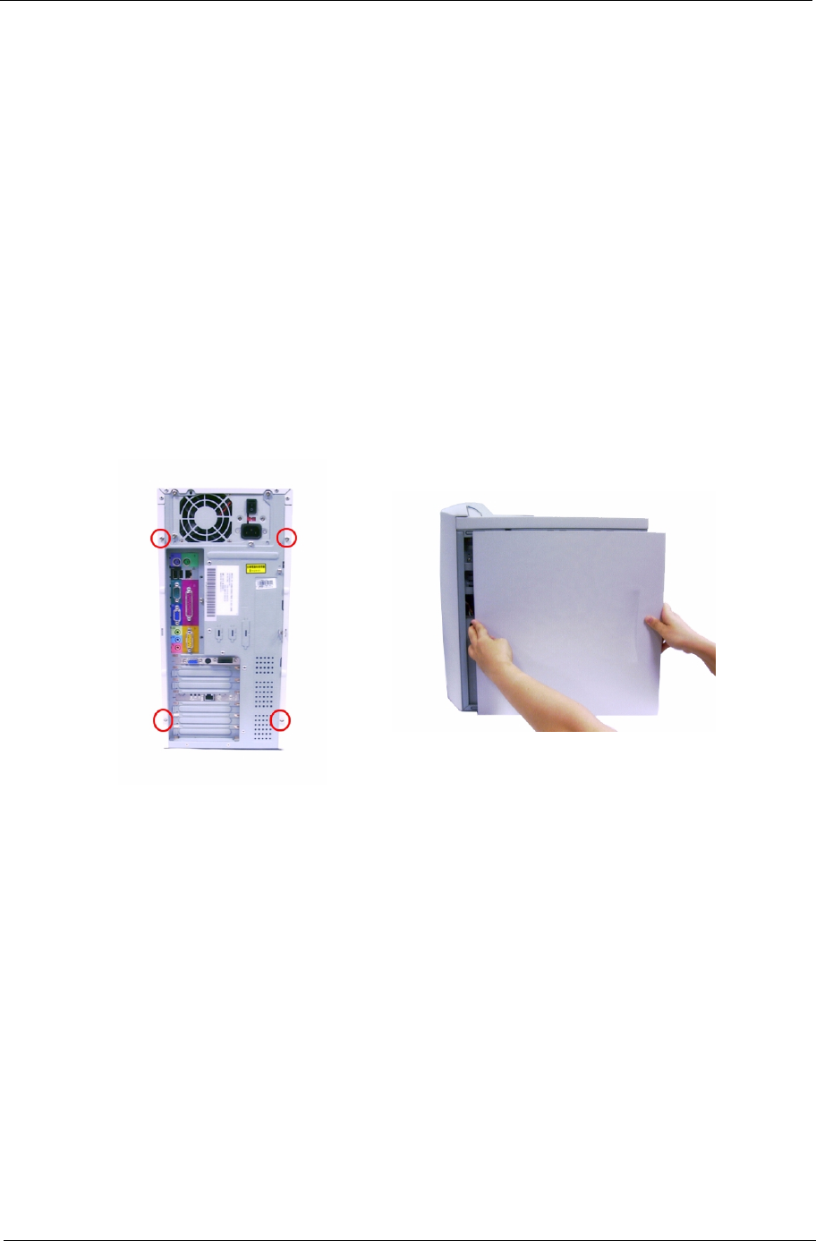
Removing the Housing Cover
1. Turn off the system power and unplug all cables.
2. Place the system unit on a flat, steady surface.
3. Remove the four screws of the right panel using a screwdriver. Set the screws aside, you will need the
when replacing the right panel of the unit.
4. Slide the right panel out and then gently pull it outward to detach it from the housing. Do the same for the
left panel.
64 Chapter 3
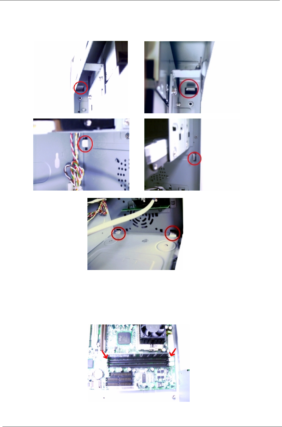
Removing the Front Panel
1. Release the 6 latches as shown below that holds the front panel and then it from the housing.
Removing a DIMM
1. Press the latches on both sides of the DIMM socket outward, to release the DIMM.
2. Then gently lift the DIMM out to remove it.
Chapter 3 65
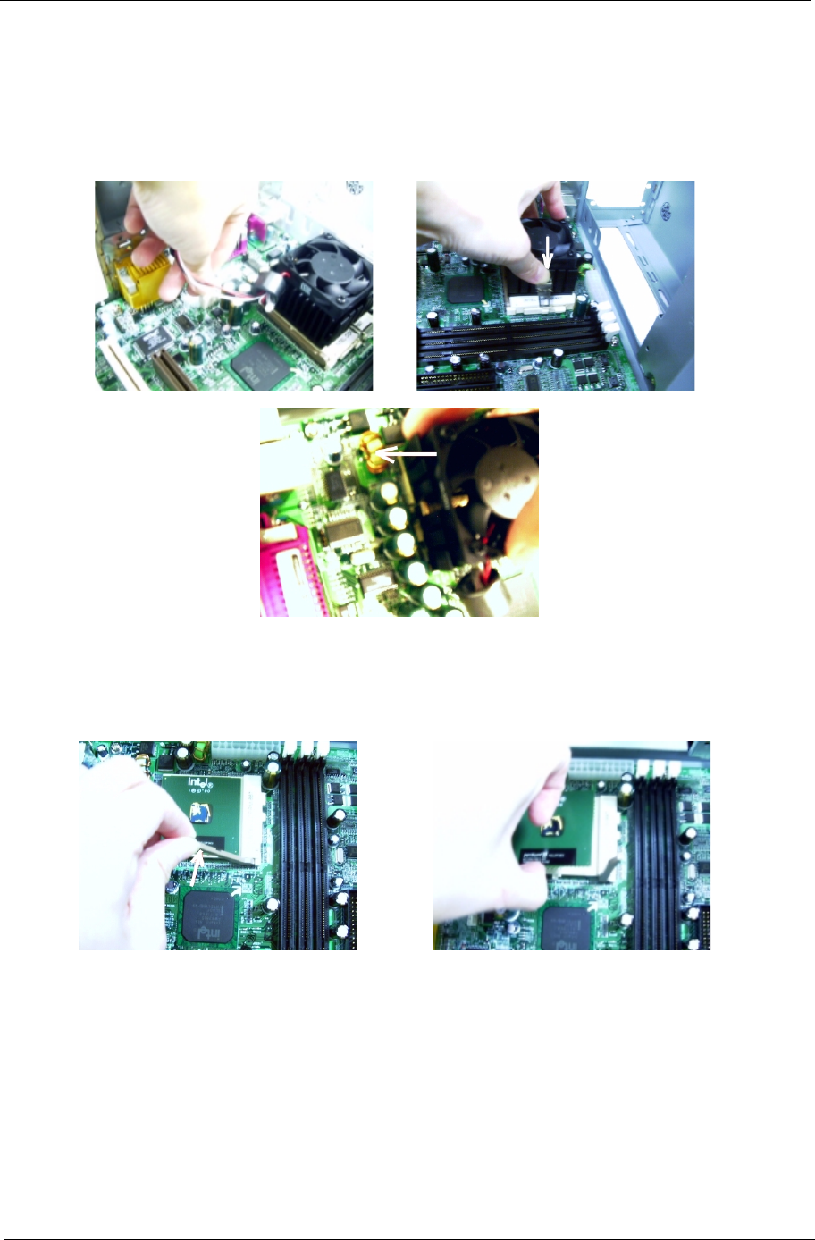
Removing the Processor
Follow these steps to remove the processor:
1. Detach the fan/heatsink cable connector .
2. Remove the fan/heatsink from the processor.
3. Pull the socket lever up to release the processor pins from the socket holes.
4. Pull out the processor from the socket.
.
WARNING:The heatsink becomes very hot when the system is On. Never touch the heatsink with any
metal or with your hands.
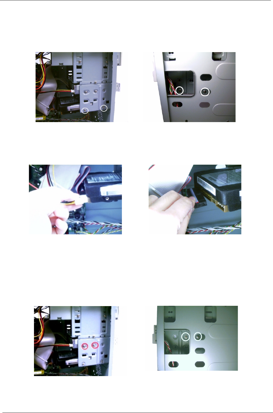
66 Chapter 3
Removing the Hard Disk
Follow these steps to remove the hard disk drive:
1. Remove the four screws that hold the hard disk drive to the disk frame. Set the screws aside.
.
2. Detach the power and disk drive cables from the hard disk drive, then detach the hard disk from the drive
frame.
.
Removing the Diskette Drive
Follow these steps to remove the diskette drive:
1. Remove the four screws holding the diskette drive.
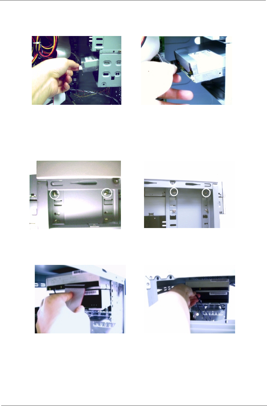
Chapter 3 67
2. Disconnect the power connector and the diskette drive cable, then remove the diskette drive from the
housing.
Removing the CD-ROM/DVD-ROM/CD-RW Drive
Follow these steps to remove the CD-ROM//DVD-ROM/CD-RW drive:
1. Remove the four screws holding the CD-ROM/DVD-ROM/CD-RW drive,
2. Disconnect the power connector, CD-ROM/DVD-ROM/CD-RW drive cable, and audio cable, then remove
the CD-ROM/DVD-ROM/CD-RW drive from the housing.

68 Chapter 3
Removing the PCI and AGP Expansion Cards
1. Remove the screw on the bracket of the expansion card. Set the screw aside, you will need it when
replacing the expansion card.
2. Gently pull out the expansion card to remove it from the expansion slot.
.
NOTE: When you turn on the system, BIOS automatically detects and assigns resources to the PCI or AGP
devices.
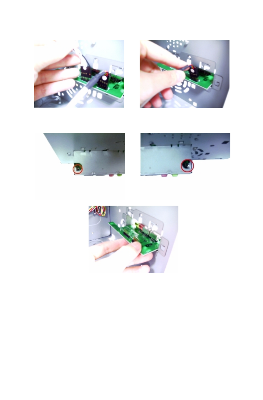
Chapter 3 69
Removing the Audio Board
1. Disconnect the audio cable and the USB cable from the audio board.
2. Remove the 2 screws that hold the audio board, then remove it from the housing.
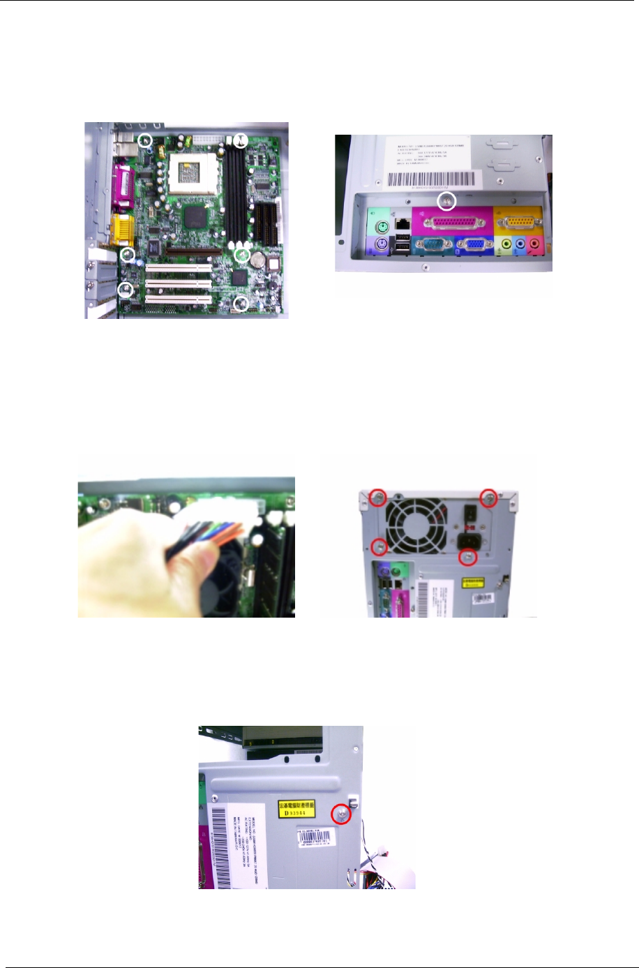
70 Chapter 3
Removing the System Main Board
1. Put the housing to lying position with the open area facing upward.
2. Remove the seven screws holding the main board and then remove the main board from the housing.
Removing the Power Supply
1. Disconnect the power supply power connector from the main board.
2. Remove the four screws holding the power supply, and then remove the power supply from the housing..
Removing the Intrusion Alarm
1. Remove the screw that secures the intrusion alarm and then remove it from the housing.

Chapter 4 71
This chapter provides troubleshooting information for the Veriton 5100/7100:
!Power-On Self-Test (POST)
!Index of Error Messages
!Index of Error Codes and Error Beeps
!Index of Error Symptoms
!Undetermined Problems
Chapter 4
Troubleshooting

72 Chapter 4
Power-On Self-Test (POST)
Each time you turn on the system, the Power-on Self Test (POST) is initiated. Several items are tested during
POST, but is for the most part transparent to the user.
The Power-On Self Test (POST) is a BIOS procedure that boots the system, initializes and diagnoses the
system components, and controls the operation of the power-on password option. If POST discovers errors in
system operations at power-on, it displays error messages on screen, generates a check point code at port
80h or even halts the system if the error is fatal.
The main components on the main board that must be diagnosed and/or initialized by POST to ensure system
functionality are as follows:
!Microprocessor with built-in numeric co-processor and cache memory subsystem
!Direct Memory Access (DMA) controller
!Interrupt system
!Three programmable timers
!ROM subsystem
!RAM subsystem
!RTC RAM subsystem and real time clock/calendar with battery backup
!Onboard serial interface controller
!Onboard parallel interface controller
!Embedded hard disk interface and one diskette drive interface
!Keyboard and auxiliary device controllers
!I/O ports
! PS/2-compatible mouse port
! PS/2-compatible keyboard port
!Serial ports
!Parallel ports
!USB port

Chapter 4 73
POST Error Messages List
If you cannot run the diagnostics program tests but did receive a POST error message, use “POST Error
Messages List” to diagnose system problems. If you did not receive any error message, look for a description
of your error symptoms in “Error Symptoms List” on page 75.
NOTE: When you have deemed it necessary to replace an FRU, and have done so, you must run a total
system check to ensure that no other activity has been affected by the change. This system check can
be done through the diagnostics program.
NOTE: Check all power supply voltages, switch, and jumper settings before you replace the main board. Also
check the power supply voltages if you have a “system no-power” condition.
If you are unable to correct the problem by using the “BIOS Messages List” table and “Error Symptoms List”
table, go to “Undetermined Problems” on page 79.
NOTE: To diagnose a problem, first find the BIOS error messages in the left column. If directed to a check
procedure, replace the FRU indicated in the check procedure. If no check procedure is indicated, the
first Action/FRU listed in right column is the most likely cause.
BIOS Messages Action/FRU
I/O Parity Error 1. System board
CPU Clock Mismatch 1. Enter BIOS Setup and load the default settings.
2. Ensure BIOS setting for processor is set correctly.
Real Time Clock Error
CMOS Battery Bad
CMOS Checksum Error
1. Enter BIOS Setup and load the default settings.
2. RTC Battery.
3. System Board.
Equipment Configuration Error 1. Ensure the system configuration set in BIOS Setup is
correct.
2. Enter BIOS Setup and load the default settings.
3. RTC battery.
4. System board.
System Management Memory Bad
Memory Error at MMMM:SSSS:OOOOh
1. Insert the memory modules in the DIMM sockets
properly, then reboot the system.
2. Memory module.
3. System board.
RAM Parity Error 1. Enter BIOS Setup to disable parity check.
2. Memory module
3. System board
PS/2 Keyboard Error or Keyboard Not Connected
PS/2 Keyboard Interface Error
PS/2 Keyboard Locked
1. Re-connect PS/2 keyboard and mouse.
2. Enter BIOS Setup and load the default settings.
3. PS/2 keyboard
4. PS/2 mouse
5. System board
Onboard xxx... Conflict(s) 1. Enter BIOS Setup and load the default settings.
2. Remove all adapter cards that are NOT factory-
installed, then reboot the system.
Floppy Disk Controller Error
Floppy Drive A Error
Floppy Drive B Error
1. Diskette drive cable/connection.
2. Diskette drive.
3. System board
On Board Parallel Port Conflict(s)
On Board Serial Port 1 Conflict(s)
On Board Serial Port 2 Conflict(s)
1. Enter BIOS Setup and load the default settings.
2. Remove all adapter cards that are NOT factory-
installed, then reboot the system.
Floppy Drive(s) Write Protected
Hard Disk Drive(s) Write Protected
1. Ensure that the diskette drive is not set to [Write
Protected] in the Security Options in BIOS Setup.
2. Load default settings in Setup.

74 Chapter 4
IDE Drive 0 Error
IDE Drive 1 Error
IDE Drive 2 Error
IDE Drive 3 Error
1. Enter BIOS Setup and load the default settings.
2. Check IDE drive jumper.
3. IDE hard disk drive power.
4. IDE hard disk drive cable/connection.
5. IDE hard disk drive.
IRQ Setting Error
Expansion ROM Allocation Fail
I/O Resource Conflict(s)
Memory Resource Conflict(s)
1. Load default settings in Setup.
2. Enter BIOS Setup and set the Reset Resource
Assignments of the PnP/PCI Options to Yes,
then reboot the system.
3. Remove all adapter cards that are NOT factory-
installed, then reboot the system
PCI Device Error 1. Load default settings in Setup.
2. Enter BIOS Setup and set the Reset Resource
Assignments of the PnP/PCI Options to Yes,
then reboot the system.
3. Remove all adapter cards that are NOT factory-
installed, then reboot the system.
PS/2 Pointing Device Interface Error
PS/2 Pointing Device Error
1. Re-connect PS/2 keyboard and mouse.
2. Enter BIOS Setup and load the default settings.
3. PS/2 mouse
4. PS/2 keyboard
5. System board
DMI Table Was Destroyed 1. Flash BIOS
Press Ctrl + Alt + Esc key to enter Setup or F1 key to
continue
1. Press Ctrl+Alt+Del to enter Setup and reconfigure the
system.
Press Esc to turn off NMI, or any key to reboot 1. Press Esc to reject NMI error or press any other key to
reboot the system.
Insert system diskette and press <Enter> key to
reboot
1. Insert a bootable disk into the floppy disk drive or
remove this disk if a hard disk is installed.
BIOS Messages Action/FRU

Chapter 4 75
Error Symptoms List
NOTE: To diagnose a problem, first find the error symptom in the left column. If directed to a check procedure,
replace the FRU indicated in the check procedure. If no check procedure is indicated, the first Action/
FRU listed in right column is the most likely cause.
Error Symptom Action/FRU
Processor / Processor Fan
NOTE: Normally, the processor fan should be operative, and the processor clock setting should be
exactly set to match its speed requirement before diagnosing any processor problems.
Processor fan does not run but power supply
fan runs.
1. Ensure the system is not in power saving mode. See “Power
Management” in chapter 2.
2. With the system power on, measure the voltage of processor fan
connector. Its reading should be +12Vdc.
3. System board.
Processor test failed. 1. Processor.
2. System board.
System Board and Memory
NOTE: Ensure the memory modules are installed properly and the contact leads are clean before
diagnosing any system problems.
Memory test failed. 1. See "Memory"
2. System board
Incorrect memory size shown or repeated
during POST.
1. Insert the memory modules in the DIMM sockets properly, then
reboot the system.
2. Memory module.
3. System board.
System works but fails to enter power saving
mode when the Power Management Mode
is set to Enabled, and power saving timer
set in BIOS has elapsed.
1. Enter BIOS Setup and load default settings.
In Windows 98, check settings in Power Management Property
of Control Panel.
2. Reload software from Recovery CD.
System hangs before system boot. 1. See "Index of Symptoms"
2. See "Undetermined Problems"
System hangs after system boot. 1. Execute a system test and set it to stop at “Halt on Error” to see
the potential cause of the problem.
2. See “Undetermined Problems”.
Blinking cursor only; system does not work. 1. Diskette/IDE drive connection/cables
2. Diskette/IDE disk drives
3. See “Undetermined Problems”.
4. System board
Diskette Drive
NOTE: Ensure the diskette drive is configured correctly in BIOS Setup and its read/write head is
clean before diagnosing any diskette drive problems.
Media and drive are mismatched. 1. Ensure the diskette drive is configured correctly in the Disk
Drives of BIOS Setup.
2. Ensure the diskette drive is correctly formatted.
3. Diskette drive connection/cable
4. Diskette drive
5. System board
Diskette drive does not work. 1. Ensure the diskette drive is not set to None in the Disk Drives of
BIOS Setup.
2. Diskette drive power
3. Diskette drive connection/cable
4. Diskette drive
5. System board

76 Chapter 4
Diskette drive read/write error. 1. Diskette.
2. Ensure the diskette drive is not set to Write protect in the
Security Options of BIOS Setup.
3. Diskette drive cable.
4. Diskette drive.
5. System board.
Diskette drive LED comes on for more than 2
minutes when reading data.
1. Diskette
2. Diskette drive connection/cable
3. Diskette drive
4. System board
Diskette drive LED fails to light, and the drive
is unable to access for more than 2 minutes.
1. Diskette
2. Diskette drive power
3. Diskette drive connection/cable
4. Diskette drive
5. System board
Diskette drive test failed. 1. Diskette
2. Diskette drive
3. Diskette drive cable
4. System board
Hard Disk Drive
NOTE: Ensure hard disk drive is configured correctly in BIOS Setup, cable/jumper are set correctly
before diagnosing any hard disk drive problems.
Hard disk drive test failed. 1. Enter BIOS Setup and Load default settings.
2. Hard disk drive cable.
3. Hard disk drive.
4. System board.
Hard disk drive cannot format completely. 1. Enter BIOS Setup and Load default settings.
2. Hard disk drive cable.
3. Hard disk drive.
4. System board.
Hard disk drive has write error. 1. Enter BIOS Setup and Load default settings.
2. Hard disk drive.
Hard disk drive LED fails to light, but system
operates normally.
1. With the system power on, measure the voltage of hard disk LED
connector.
2. Hard drive LED cable.
CD/DVD-ROM Drive
NOTE: Ensure CD/DVD-ROM drive is configured correctly in BIOS Setup, cable/jumper are set
correctly and its laser beam is clean before diagnosing any CD/DVD-ROM drive problems.
CD/DVD-ROM drive LED doesn't come on
but works normally.
1. CD/DVD-ROM drive
CD/DVD-ROM drive LED flashes for more
than 30 seconds before LED shutting off.
Software asks to reinstall disc.
Software displays a reading CD/DVD error.
1. CD/DVD-ROM may have dirt or foreign material on it. Check with
a known good disc.
2. CD/DVD-ROM is not inserted properly.
3. CD/DVD-ROM is damaged.
CD/DVD-ROM drive cannot load or eject
when the system is turned on and its eject
button is pressed and held.
1. Disconnect all cables from CD/DVD-ROM drive except power
cable, then press eject button to try to unload the disk.
2. CD/DVD-ROM drive power.
3. CD/DVD-ROM drive
CD/DVD-ROM drive does not read and there
are no messages are displayed.
1. CD may have dirt or foreign material on it. Check with a known
good disc.
2. Ensure the CD/DVD-ROM driver is installed properly.
3. CD/DVD-ROM drive.
Error Symptom Action/FRU

Chapter 4 77
CD/DVD-ROM drive can play audio CD but
no sound output.
1. Ensure the headphone jack of the CD/DVD-ROM has an output.
2. Turn up the sound volume.
3. Speaker power/connection/cable.
4. CD/DVD-ROM drive.
Real-Time Clock
Real-time clock is inaccurate. 1. Ensure the information in the Date and Time of BIOS Setup is
set correctly.
2. RTC battery.
3. System board
Audio
Audio software program invokes but no sound
comes from speakers.
1. Speaker power/connection/cable.
Modem
Modem ring cannot wake up system from
suspend mode.
1. Ensure the Modem Ring Indicator in BIOS Setup or Power
Management is set to Enabled.
2. If PCI modem card is used, reinsert the modem card to PCI slot
firmly or replace the modem card.
3. If ISA modem card is used, ensure the modem ring-in cable from
the modem card to system board is connected properly.
4. In Win 98, ensure the telephone application is configured
correctly for your modem and set to receive messages and/or
fax.
Data/fax modem software program invokes
but cannot receive/send data/fax
1. Ensure the modem card is installed properly.
Fax/voice modem software program invokes
but has no sound output. (Data files are
received normally; voice from modem cannot
be produced, but system sound feature works
normally.)
1. Ensure the modem voice-in cable from modem adapter card to
system board
Video and Monitor
Video memory test failed.
Video adapter failed.
1. Remove all non-factory-installed cards.
2. Load default settings (if screen is readable).
3. System board
Display problem:
- Incorrect colors
No high intensity
Missing, broken, or incorrect characters
Blank monitor(dark)
Blank monitor(bright)
Distorted image
Unreadable monitor
Other monitor problems
1. Monitor signal connection/cable.
2. Monitor
3. Video adapter card
4. System board
Display changing colors. 1. Monitor signal connection/cable
2. Monitor
3. System board
Display problem not listed above (including
blank or illegible monitor).
1. “Monitor".
2. Load default settings (if screen is readable).
3. System board
Error Symptom Action/FRU

78 Chapter 4
Parallel/Serial Ports
Execute “Load BIOS Default Settings” in BIOS Setup to confirm ports presence before diagnosing any parallel/serial
ports problems.
Serial or parallel port loop-back test failed. 1. Make sure that the LPT# or COM# you test is the same as the
setting in BIOS Setup.
2. Loop-back.
3. System board.
Printing failed. 1. Ensure the printer driver is properly installed. Refer to the printer
service manual.
2. Printer.
3. Printer cable.
4. System board.
Printer problems. 1. Refer to the service manual for the printer.
Keyboard
Some or all keys on keyboard do not work. 1. Keyboard
Power Supply
Pressing power switch does not turn off
system. (Only unplugging the power cord
from electrical outlet can turn off the system.)
1. Ensure the Power Switch < 4 sec. in BIOS Setup of Power
Management is not set to Suspend.
2. Power switch cable assembly
Pressing power switch does not turn on the
system.
1. Ensure the power override switch (situated at the back of the
machine, just above the connector for the power cable) is not set
to OFF.
2. Power switch cable assembly.
Executing software shutdown from
Windows98 Start menu does not turn off the
system. (Only pressing power switch can turn
off the system).
1. Load default settings.
2. Reload software from Recovery CD.
No system power, or power supply fan is not
running.
1. Power Supply
2. System Board
Other Problems
Any other problems. 1. Undetermined Problems
Error Symptom Action/FRU

Chapter 4 79
Undetermined Problems
If an error message is present, go to “POST Error Messages List” on page 73. If you did not receive any
messages, see if the symptom is listed in “or “Error Symptoms List” on page 75. If you still cannot solve the
problem, continue with this check:
1. Check the power supply voltages. If the voltages are correct continue with the following steps:
2. Power off the system unit.
3. Perform the following checks, one by one, until you have isolated the
problem FRU.
4. Load default settings in setup.
5. Check all system board jumper positions and switch settings.
6. Check all adapter card jumper positions.
7. Check all device jumper positions.
8. Check all cables and connectors for proper installation.
9. If the jumpers, switches and voltage settings are correct, remove or disconnect the following, one at a
time:
10. Non-Acer devices
!External devices
!Any adapter card (modem card, LAN card or video card, if installed)
!CD/DVD-ROM drive
!Diskette drive
!Hard disk drive
!DIMM
!Processor
!System board
11. Power on the system unit.
12. Repeat steps 2 through 5 until you find the failing device or adapter.

80 Chapter 4
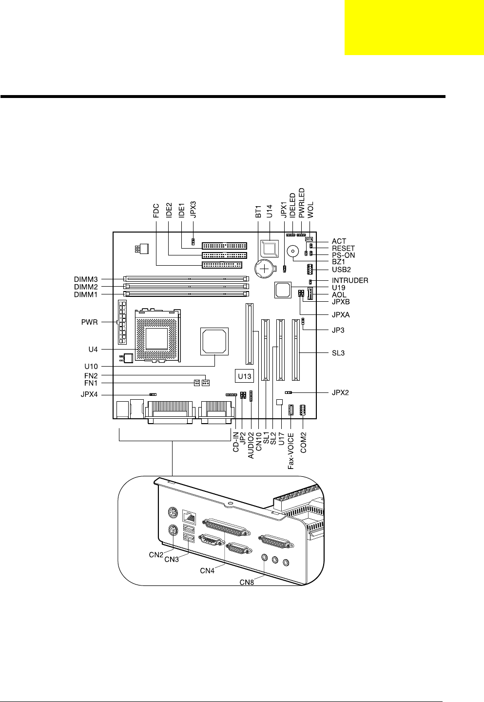
Chapter 5 81
Jumpers and Connectors
Refer to the following figure for the location of the jumpers and connectors on the main board:
Main board
Jumper and Connector Information
Chapter 5

82 Chapter 5
Connector Description
Connector No. Description
ACT Turbo/LAN active LED connector
AOL Alert on LAN connector
AUDIO2 Audio connector for USB-audio board
BT1 Battery
BZ1 Buzzer
CD-IN CD-ROM audio connector
CN2 PS/2 mouse (upper) and keyboard (lower) ports
CN3 Network (upper) and USB (lower) ports
CN4 Parallel (upper), VGA (lower right) and serial port 1 (lower left)
ports
CN8 MIDI/game (upper), line-out (left), line-in (middle), and mic-in
(right) ports
CN10 AGP slot
COM2 Serial port 2 (COM2) connector (optional)
DIMM 1 to 3 DIMM sockets 1 to 3
FDC Floppy disk drive connector
FN1 2-pin CPU fan connector
FN2 3-pin CPU fan connector
IDELED IDE LED connector
IDE1 IDE 1 HDD connector
IDE2 IDE 2 HDD connector
INTRUDER Intrusion alarm connector
PS-ON ATX power switch
PWR ATX power connector
PWRLED Power LED connector
RESET Reset button connector
SL 1 to 3 PCI slots 1 to 3
USB2 USB connector for USB-audio board
U4 FC-PGA CPU socket
U10 Intel 82815 chipset
U13 Super I/O chipset
U14 Firmware HUB (BIOS)
U17 Audio chipset
U19 Intel 82801BA chipset
WOL Wake on LAN connector

Chapter 5 83
Jumper Setting
NOTE: *: Default Settings
Jumper Function and settings
JP2
1-3, 2-4
3-5, 4-6*
Line-out options
Unamplified
Amplified
JP3
1-2*
2-3
LAN EEPROM
Enabled
Disabled
JPXA
1-2
2-3*
Boot block
Enabled
Disabled
JPXB
1-2
2-3*
Check password
Enabled
Disabled
JPX1
1-2
2-3*
CMOS clear
Clear CMOS
Normal
JPX2
1-2
2-3*
CPU speed
Safe mode
Normal
JPX3
1-2*
2-3
Support CPU
Coppermine/Celeron
VIA (Cyrix)/Joshua
JPX4
1-2*
2-3
Onboard LAN
Enabled
Disabled
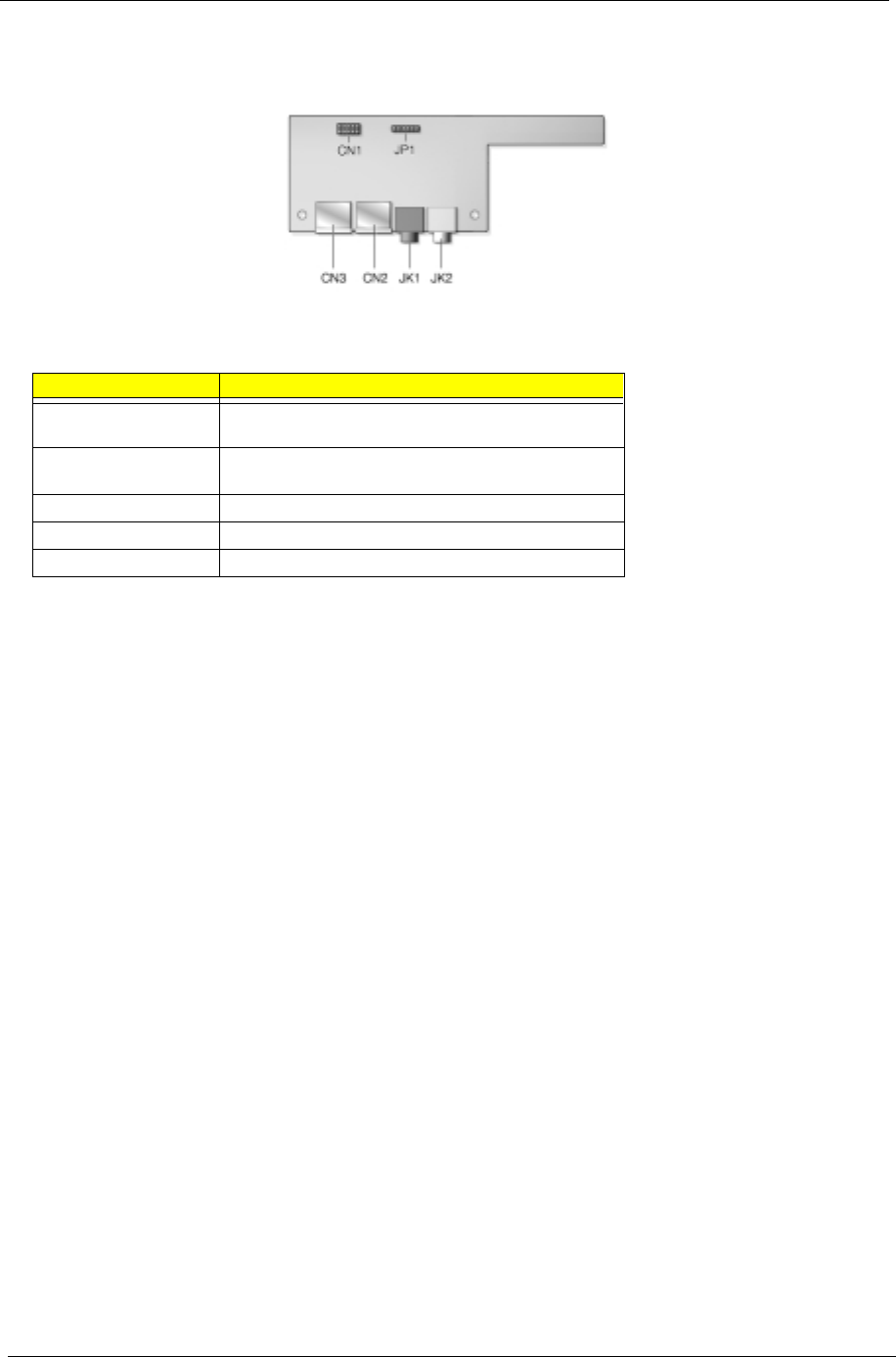
84 Chapter 5
Audio Board
Connector No. Description
JP1 Audio connector-connects to the AUDIO2 connector of
the mainboard
CN1 USB connector-connects to the USB2 connector of the
mainboard
CN2, CN3 USB ports
JK1 Microphone-in port
JK2 Audio-out port

85
This chapter gives you the FRU (Field Replaceable Unit) listing in global configurations of Veriton 5100/7100.
Refer to this chapter whenever ordering for parts to repair or for RMA (Return Merchandise Authorization).
IMPORTANT: Please note WHEN ORDERING FRU PARTS, that you should check the most up-to-date
information available on your regional web or channel. For whatever reasons a part number change
is made, it will not be noted in the printed Service Guide. For ACER-AUTHORIZED SERVICE
PROVIDERS, your Acer office may have a DIFFERENT part number code to those given in the FRU
list of this printed Service Guide. You MUST use the local FRU list provided by your regional Acer
office to order FRU parts for repair and service of customer machines.
NOTE: To scrap or to return the defective parts, you should follow the local government ordinance or
regulations on how best to dispose it, or follow the rules set by your regional Acer office on how to
return it.
NOTE: The number indicates the location shown on exploded diagram or “NS” indicates “Not shown” on it.
FRU (Field Replaceable Unit) List
Chapter 6
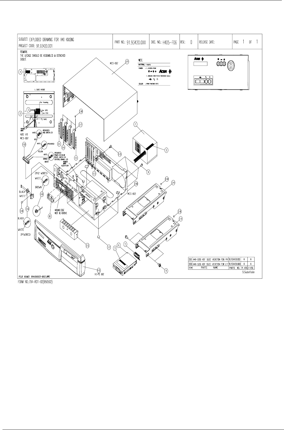
86 Chapter 6
Veriton 5100 Exploded Diagram
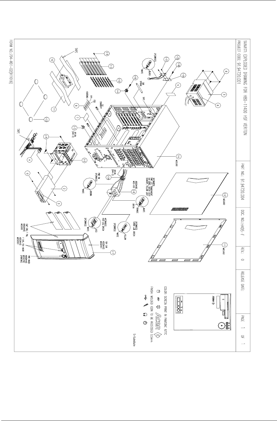
Chapter 6 87
Veriton 7100 Exploded Diagram
88 Chapter 6
Picture No. Partname Description Part No. 5100 7100
CPU
NS CPU,COPPERMINE733
MHZ,133M,256K,
FCPGA,SOCKET370,INT
EL
IC CPU COP733/133/
256 FCPGA B0
01.COPRM.73C X X
CPU,COPPERMINE
667MHZ,133M,256K,
FCPGA,SOCKET
370,INTEL
IC CPU COP667/133/
256 FCPGA B0
01.COPRM.66C X X
CPU,COPPERMINE
600MHZ,100M,256K,
FCPGA,SOCKET
370,INTEL
IC CPU COP600/100/
256 FCPGA B0
01.COPRM.60I X X
CPU,CELERON 533MHZ
,66M,128K,FCPGA,
SOCKET 370,INTEL
IC CPU CELER533A/
128K/66M 0D
01.ICLON.53A X X
CPU,CELERON 566MHZ
,66M,128K,FCPGA,
SOCKET 370,INTEL
IC CPU CELER566/
128K/66M 0D
01.ICLON.566 X X
CPU,CELERON 600MHZ
,66M,128K,FCPGA,
SOCKET 370,INTEL
IC CPU CELER600/
128K/66M 0D
01.ICLON.600 X X
CPU,COPPERMINE
933MHZ ,133M,256K,
FCPGA,SOCKET
370,INTEL
IC CPU COPP933/133/
256 FCPGA
01.COPRM.933 X X
CPU,COPPERMINE
866MHZ,133M,256K,
FCPGA,SOCKET
370,INTEL
IC CPU COPP866/133/
256/0D FCPG
01.COPRM.866 X X
CPU,COPPERMINE
800MHZ,133M,256K,
FCPGA,SOCKET
370,INTEL
IC CPU COPP800B/
133/256/0D FCP
01.COPRM.800 X X
CPU,COPPERMINE
600MHZ,133M,256K,
FCPGA,SOCKET
370,INTEL
IC CPU COP600/133/
256 FCPGA B0
01.COPRM.60H X X
CPU,COPPERMINE
800MHZ,100M,256K,
FCPGA,SOCKET
370,INTEL
IC CPU COPP800/100/
256/0D FCPG
01.COPRM.80B X X
CPU,COPPERMINE
750MHZ,100M,256K,
FCPGA,SOCKET
370,INTEL
IC CPU COP750/100/
256 FCPGA B0
01.COPRM.75G X X
CPU,COPPERMINE
700MHZ,100M,256K,
FCPGA,SOCKET
370,INTEL
IC CPU COP700/
100256 FCPGA B0
01.COPRM.70G X X
CPU,COPPERMINE
650MHZ,100M,256K,
FCPGA,SOCKET
370,INTEL
IC CPU COP650/100/
256 FCPGA B0
01.COPRM.65E X X
Chapter 6 89
NS FANSINK,3PIN,SOCKET
370
Fan Sink SKT370 3-pin
AI
90.00028.632 X
FANSINK,2PIN,SOCKET
371
Fan Sink SKT370 2-pin 90.00028.641 X
Memory
NS MEMORY,SDIMM,128MB
,PC-133,INFINEON
SDIMM 128M
64V16220GU-7.5C
(ACE)
72.64162.L05 X X
MEMORY,SDRAM,64MB,
PC-100,INFINEON
SDRAM 64MB
HYS64V8300GU-8-
C(A)
72.64830.L03 X X
MEMORY,DIMM,128MB,
PC-133,MICRON
DIMM 128M
MT16LSDT1664AG-
133C7
72.16664.L04 X X
MEMORY,SDIMM,128MB
,PC-100,MICRON
SDIMM 128M
MT16LSDT1664AG-
10EC
72.16164.L03 X X
MEMORY,DIMM,64MB,P
C-133,MICRON
DIMM 64M
MT8LSDT864AG133C
7
72.08864.L05 X X
MEMORY,SDIMM,32MB,
PC-100,MICRON
SDIMM 32M
MT4LSDT464AG-
10EC5
72.04464.L04 X X
Monitor
NS 15" (110V North
Hemisphere)--AAC/ACLA
91.71602.301 X X
(Universial 220/110V
North Hemisphere)--ACI/
AEB/ACLA
91.71602.302 X X
(Universial 220/110V
Equatorial Hemisphere)--
ACI/ACLA
91.71602.303 X X
(Universial 220/110V
South Hemisphere)--ACI
91.71602.304 X X
(Universial 110V North
Hemisphere)--STK
91.71602.305 X X
17"--AAC/ACLA 91.70602.107 X X
17"--ACI/AEB 91.70602.108 X X
17"--AAC/ACLA 91.70602.109 X X
17"--ACI (N.Z. &
Australia)
91.70602.110 X X
17"--STK Taiwan 91.70602.111 X X
17"(TCO) 91.70602.112 X X
FDD/Floppy Disk Drive
6, 2 FDD,1.44MB,3
MODE,PANASONIC/
JU-256A046P
FDD 1.44
JU-256A046P ACER
V.S
56.01057.194 X X
Picture No. Partname Description Part No. 5100 7100
90 Chapter 6
HDD/Hard Disk Drive
NS HDD,
30GB,IDE,QUANTUM/
30.0AT LC30A
HDD 30G 4400 QTM/
30.0AT LC30A
56.02B92.021 X X
HDD,
30GB,IDE,MAXTOR/
ATV33073H4
HDD 30G MX5400/
ATV33073H4 DE
56.02B93.031 X
HDD,
20.4GB,IDE,SEAGATE/
ST320423A
HDD 20.4GB
SEAGATE/ST320423A
56.02B34.051 X X
HDD,
20GB,IDE,ATA2,SEAGAT
E/ST320420A
HDD 20G ATA2 7200
SG/ST320420A
56.02B34.091 X X
HDD,
10.2GB,IDE,SEAGATE/
ST310212A
HDD 10.2GB
SEAGATE/ST310212A
56.02A72.081 X X
HDD ,
15.3GB,IDE,SEAGATE/
ST315323A
HDD 15.3GB
SEAGATE/ST315323A
56.02B65.001 X X
HDD,
15GB,IDE,SEAGATE/
ST315320A
HDD 15G ATA2 7200
SG/ST315320A
56.02B65.021 X X
HDD ,
7.5GB,IDE,QUANTUM/
7.5AT LC07A
HDD 7.5G 4500 QTM/
7.5AT LC07A
56.02A62.001 X X
HDD,
15GB,IDE,QUANTUM/
15.0AT LC15A
HDD 15G 4400 QTM/
15.0AT LC15A
56.02B64.021 X X
HDD,
20.4GB,IDE,QUANTUM/
20.4ATLC20A
HDD 20.4GB
4400QUA/
20.4ATLC20A
56.02B33.051 X X
CD-ROM Drive
NS CD-ROM ,
48X,AOPENCD-948E
CD ROM CD-948E/
AKUF 48X
91.32D37.407 X X
CDROM,48X,IDE,API/
650P-047
CD ROM 48X API/
650P-047
56.10213.001 X
CD-RW Drive
NS CD-RW,8/4/32X,LG/CED-
8080B
CD-RW 8/4/32X LG/
CED-8080B IBE
56.1938H.031 X
CD-RW,8*4*32X,ISONY/
CRX140E
CD-RW 8*4*32X
SONY/CRX140E
56.1938H.001 X X
CD-RW 8/4/32 SONY/
CRX140E-AC
CD-RW 8/4/32 SONY/
CRX140E-AC
56.1938H.011 X X
CD-RW 8/4/32X LG/CED-
8080B AC
CD-RW 8/4/32X LG/
CED-8080B AC
56.1938H.021 X X
DVD-ROM Drive
NS DVD ROM 8/40X
HITACHI/GD-5000BVAC
DVD ROM 8/40 HIT/
GD-5000BVAC
56.2232G.012 X X
DVD ROM 8X/40X
HITACHI/ GD-7000ACO
DVD 8X/40X HITACHI/
GD-7000ACO
56.2238H.011 X X
Picture No. Partname Description Part No. 5100 7100
Chapter 6 91
Cables
NS IDE CABLE,40PIN,3C C.A 40P 3CON
450MM IDE ID2M
50.00509.041 X X
IDE CABLE,40PIN,3C C.A 40P 3C
250+100MM IDE H61
50.92207.001 X X
IDE
CABLE,ULTRA66,40PIN,
3C
C.A 80P 2CON
210MM ULTRA 66
50.95704.001 X
IDE
CABLE,ATA66,40PIN,3C
C.A 40P 3C
150+300mmATA66
H20
50.91209.001 X X
IDE CABLE,40PIN,3C C.A 40P 3C
150+300MM IDE H61
50.92207.031 X X
NS FDD CABLE,34PIN,2C C.A 34P 2C 450MM
FDD H61
50.92205.021 X X
FDD CABLE,34PIN,2C C.A 34P 2C 350MM
FDD M19A/FU
50.54A08.001 X X
NS CDROM AUDIO(Y)
CABLE,4PIN,3C
W.A 4P 3C(Y)520MM
AUDIO(COMAX
50.37702.051 X X
CDROM AUDIO
CABLE,4PIN,2C
W.A 4P 2C AUDIO
520MM H61
50.37702.041 X X
AUDIO CABLE,6/5 PI W.A 6/5P 380MM
IRDA TIFA
50.39C05.001 X X
NS INTRUSION ALERM
CABLE MODULE
HOUSING DOOR
ALARM SET AP8600
6K.30C01.001 X
USB CABLE,10PIN C.A USB/10P 260MM
H61
50.92216.001 X X
Main Board
NS Main Board/S58M S58M MB Solano IICH 55.38H01.001 X X
Boards
NS LAN BOARD,10/100
Mbps,3COM/3C905C-
TXM
LAN CARD 3COM/
3C905C-TXM
54.03091.021 X X
LAN BOARD,10/100
Mbps,ANI/ALN-325
LAN 8139B-F ANI/
ALN-325
54.03111.021 X X
LAN BOARD,10/100
Mbps,ANI/ALN-325
LAN 8139B-F ANI/
ALN-325
56.0735G.011 X X
Picture No. Partname Description Part No. 5100 7100
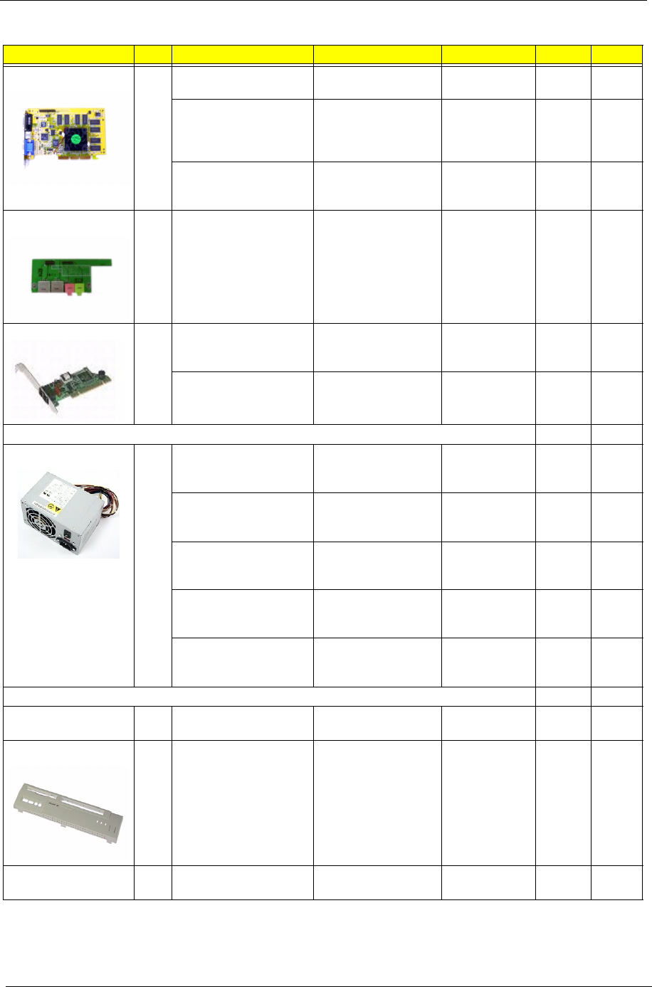
92 Chapter 6
NS VGA BOARD,32MB,ATI/
RAGE 128 PRO
VGA ATI/RAGE 128
PRO 32MB S58M
54.02023.071 X
VGA BOARD,32MB SDR
+ TV Out +
DVI,LEADTEK /
WINFAST GEFORCE256
VGA WINFAST
GEFORCE256 DVI
S61
54.02023.061 X X
VGA BOARD,32MB
,LEADTEK / WINFAST
3D S325
VGA BD WINFAST 3D
S325 S61
54.02023.051 X X
NS USB/AUDIO DAUGHTER
BOARD
S58M USB/AUDIO
DAUGHTER BOARD
55.38H02.001 X X
NS MODEM
BOARD,56K,AMBIT/
MRT62M154
MODEM 56K D/F
AMBIT/MRT62M154
54.09011.281 X X
MODEM BOARD,56K
,ASKEY/1456VQH20E
MODEM D/F 56K
ASKEY/1456VQH20E
54.09551.051 X X
Power Supply
NS POWER
SUPPLY,145W,API/API-
9502-072
SPS 145W API-9502-
072 REV.A
56.04145.552 X
POWER
SUPPLY,145W,DELTA/
DPS-145PB-82A
SPS 145W DEL/DPS-
145PB-82A R01
56.04145.1Q2 X
POWER
SUPPLY,145W,HI-PWR/
SI-X145M3
SPS 145W HI-PWR/SI-
X145M3 V.B1
56.04145.4U1 X
POWER
SUPPLY,200W,DELTA/
DPS-200BP-95B
SPS 200W DELTA/
DPS-200BP-95B
56.04200.1U1 X
POWER
SUPPLY,200W,HP/SI-
X200M3
SPS 200W HP/SI-
X200M3
56.04200.4X2 X
Case/Cover/Bracket assembly
I/O PORT BRACKET ASSY PORT BRKT
B2UL FGA H61
60.92206.111 X X
1 FRONT PANEL MAIN COVER / VER
H40
42.93416.011 X
NS RIGHT PANEL RIGHT COVER / VER
H40
42.93417.011 X
Picture No. Partname Description Part No. 5100 7100
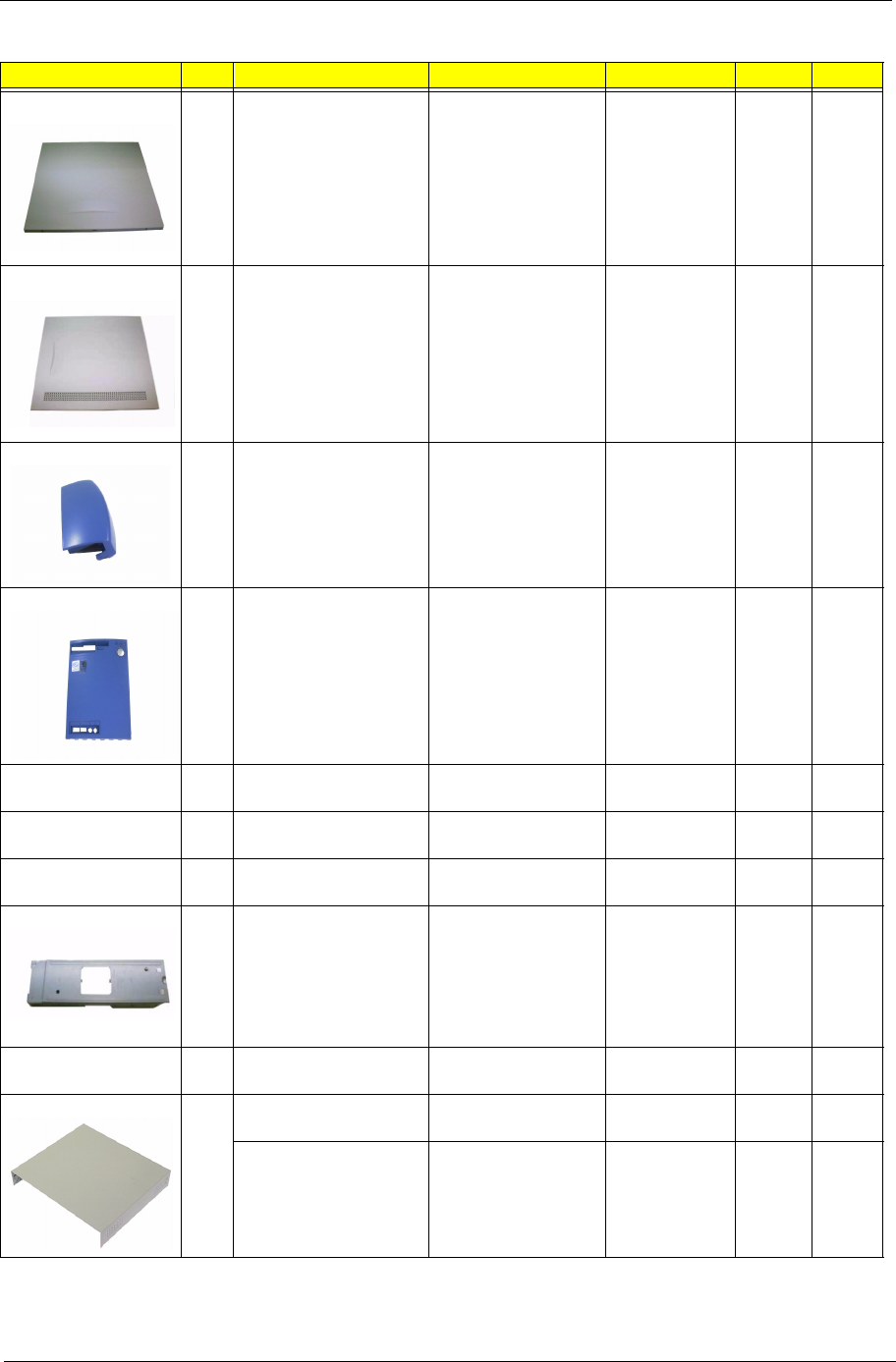
Chapter 6 93
1-1 RIGHT PANEL CVR R SECC T-.8
LX45
31.93302.001 X
1-2 LEFT PANEL CVR L SECC T-.8 H80 31.94701.001 X
1-7 TOP COVER TOP COVER D501
H80 (VERITON)
42.94701.011 X
1-7 FRONT COVER FRONT COVER D501
H80 (VERITON)
42.94705.011 X
10 USB COVER USB COVER / VER
H40
42.93418.001 X
10 USB COVER USB COVER D501
H80 (VERITON)
42.94708.011 X
NS ADD-ON PORT
BRACKET
BKT PORT SECC H51 33.94600.001 X
1-4 LINK BAR LINK BAR SGCC H40 34.93401.011 X
NS POWER SWITCH
CABLE,2PIN
W.A 2P/PWR SW
300MM H61 W/HOLD
50.92201.002 X
1-9 UPPER CASE ASSY UP CASE 002
H40
60.93401.021 X
UPPER CASE ASSY UPPER CASE
H40
60.93401.001 X
Picture No. Partname Description Part No. 5100 7100
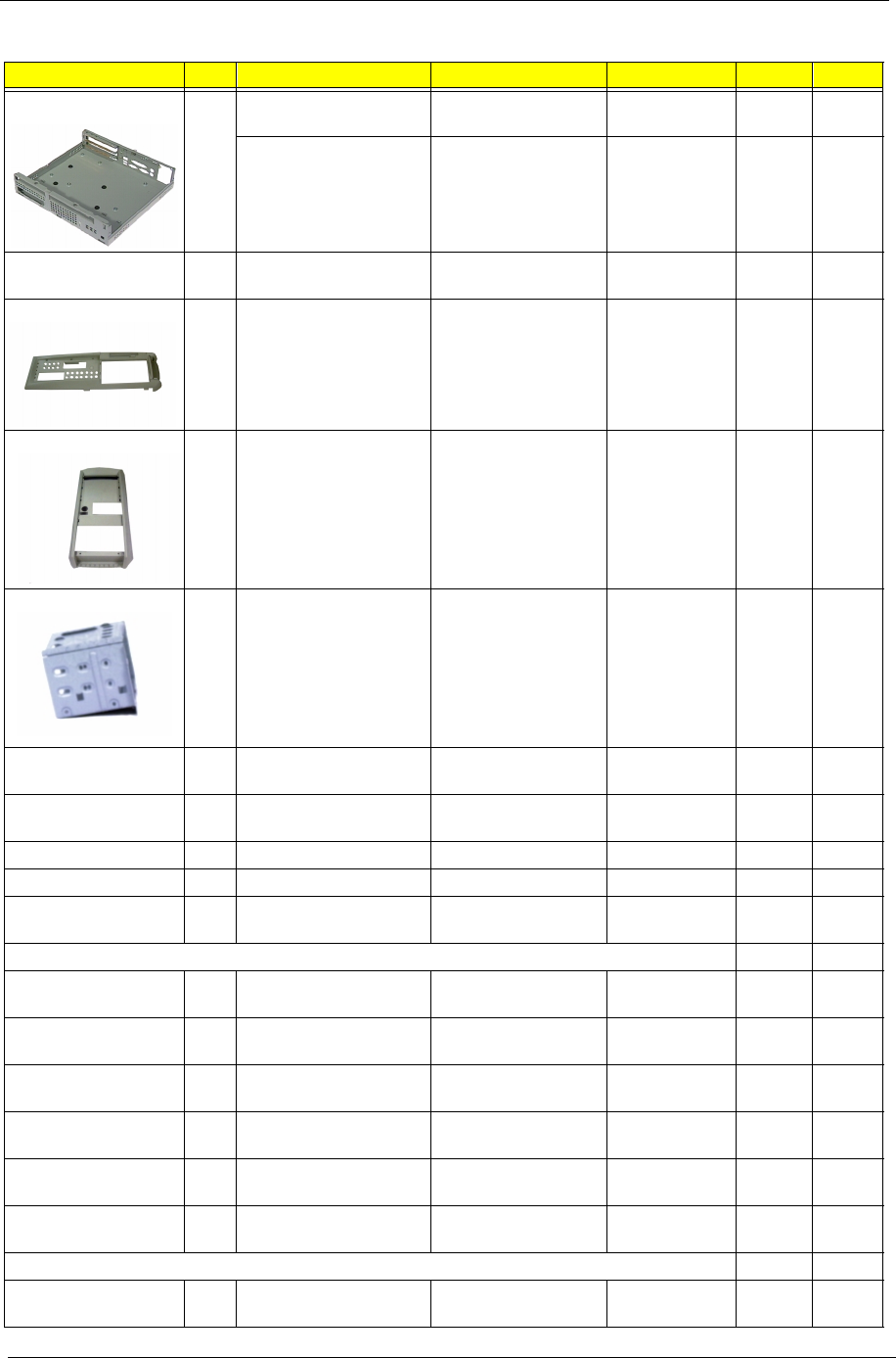
94 Chapter 6
1-10 LOWER CASE ASSY L CASE 002
H40
60.93402.021 X
LOWER CASE ASSY L CASE H40 60.93402.004 X
1-6 LOWER CASE ASSY L-CASE W/USB
HOLE H80
60.94707.011 X
1-11 FRONT BEZEL F PNL / VER H40 41.93405.011 X
1-7 FRONT BEZEL FRONT BZL D002 H80
(VERITON)
41.94701.011 X
1-3 FDD FRAME FRAME FDD 3.5"
SECC T-.6 LX45
34.93302.002 X
NS EMPTY DRIVE COVER
5.25"
CVR EMPTY 525 CHA
HIPS 002 H61
42.92221.011 X
NS EMPTY DRIVE 5.25"
COVER
CVR EMPTY 525 CHA
ABS 002 H80
42.92221.041 X
NS LED CABLE ASSY ASSY LED CABLE H40 60.93405.001 X
NS LED HOLDER MODULE ASSY HLD LX45 60.93305.002 X
NS Intrusion Alert Micro
Switch Cable Module
ASSY MICRO SW
CABLE H40
60.93407.011 X
Screws
NS SPS,Port Bracket, LINK
BAR,Mainboard SCREW
SCRW MACH PAN W/
SPG#6-32*5/16
86.1B526.7R9 X X
NS DVD/CDROM/CD-RW
SCREW
SCRW PAN W/FLT
SPG M3*6L NI
86.1H524.6R0 X X
NS HDD SCREW SCRW MACH BDG #6-
32*3/16" NI
86.4A5A6.012 X X
1-3,
1-4
KEY LOCK SCREW SCRW MACH FLAT
M3*0.5P*8L NI
86.5A524.8R0 X X
NS FDD SCREW SCRW TAP HEX ZINC
M3*.5*5
86.BA224.5R0 X X
NS UPPER CASE SCREW SCRW THUMB #6-32
NI
86.00934.A60 X
Miscellaneous parts
NS NAME PLATE NAME PLT W/O
COL10.25*20.75 PC
40.41306.011 X X
Picture No. Partname Description Part No. 5100 7100

Chapter 6 95
Keyboard
NS KEYBOARD,104KEYS,U
SB,US,DARFON
KB US 104KEYS 99.P5181.041 X X
KEYBOARD,104KEYS,P
S/2,US,DARFON
KB US 104 KEY API
6511-CX(62C)
91.62C07.041 X X
KEYBOARD,105KEYS,P
S/2,SWISS,DARFON
KB 105KEYS SWISS/
US
91.62C07.040 X X
KEYBAORD, 105KEYS
,PS/
2,SPANISH,DARFON
KB 105KEYS
SPANISH/US
91.62C07.042 X X
KEYBOARD 104KEYS
THAILAND PS/2
DARFON
KB 104KEYS
THAILAND
91.62C07.043 X X
KEYBOARD 104KEYS
INTERNATIONAL/US PS/
2 DARFON
KB 104KEYS
INTERNATIONAL/US
91.62C07.046 X X
KEYBOARD 104KEYS
CZECH/US PS/2
DARFON
KB 104KEYS CZECH/
US
91.62C07.049 X X
KEYBOARD 104KEYS
ARABIC/US PS/2
DARFON
KB 104KEYS ARABIC/
US
91.62C07.04A X X
KEYBOARD 105KEYS
BELGIUM/US PS/2
DARFON
KB 105KEYS
BELGIUM/US
91.62C07.04B X X
KEYBOARD 104KEYS
CHINESE/US PS/2
DARFON
KB 104KEYS
CHINESE/US
91.62C07.04C X X
KEYBOARD 105KEYS
DANISH/US PS/2
DARFON
KB 105KEYS DANISH/
US
91.62C07.04D X X
KEYBOARD 105KEYS
ITALIAN/US PS/2
DARFON
KB 105KEYS ITALIAN/
US
91.62C07.04E X X
KEYBOARD 105KEYS
FRENCH/US PS/2
DARFON
KB 105KEYS
FRENCH/US
91.62C07.04F X X
KEYBOARD 105KEYS
GERMAN/US PS/2
DARFON
KB 105KEYS
GERMAN/US
91.62C07.04G X X
KEYBOARD 104KEYS
HEBREW/US PS/2
DARFON
KB 104KEYS
HEBREW/US
91.62C07.04H X X
KEYBOARD 104KEYS
SLOVAKIAN/US PS/2
DARFON
KB 104KEYS
SLOVAKIAN/US
91.62C07.04L X X
KEYBOARD 105KEYS
ICELAND/US PS/2
DARFON
KB 105KEYS
ICELAND/US
91.62C07.04M X X
KEYBOARD 105KEYS
NORWEGIAN PS/2
DARFON
KB 105KEYS
NORWEGIAN
91.62C07.04N X X
KEYBOARD 105KEYS
HOLLAND PS/2
DARFON
KB 105KEYS
HOLLAND
91.62C07.04O X X
Picture No. Partname Description Part No. 5100 7100
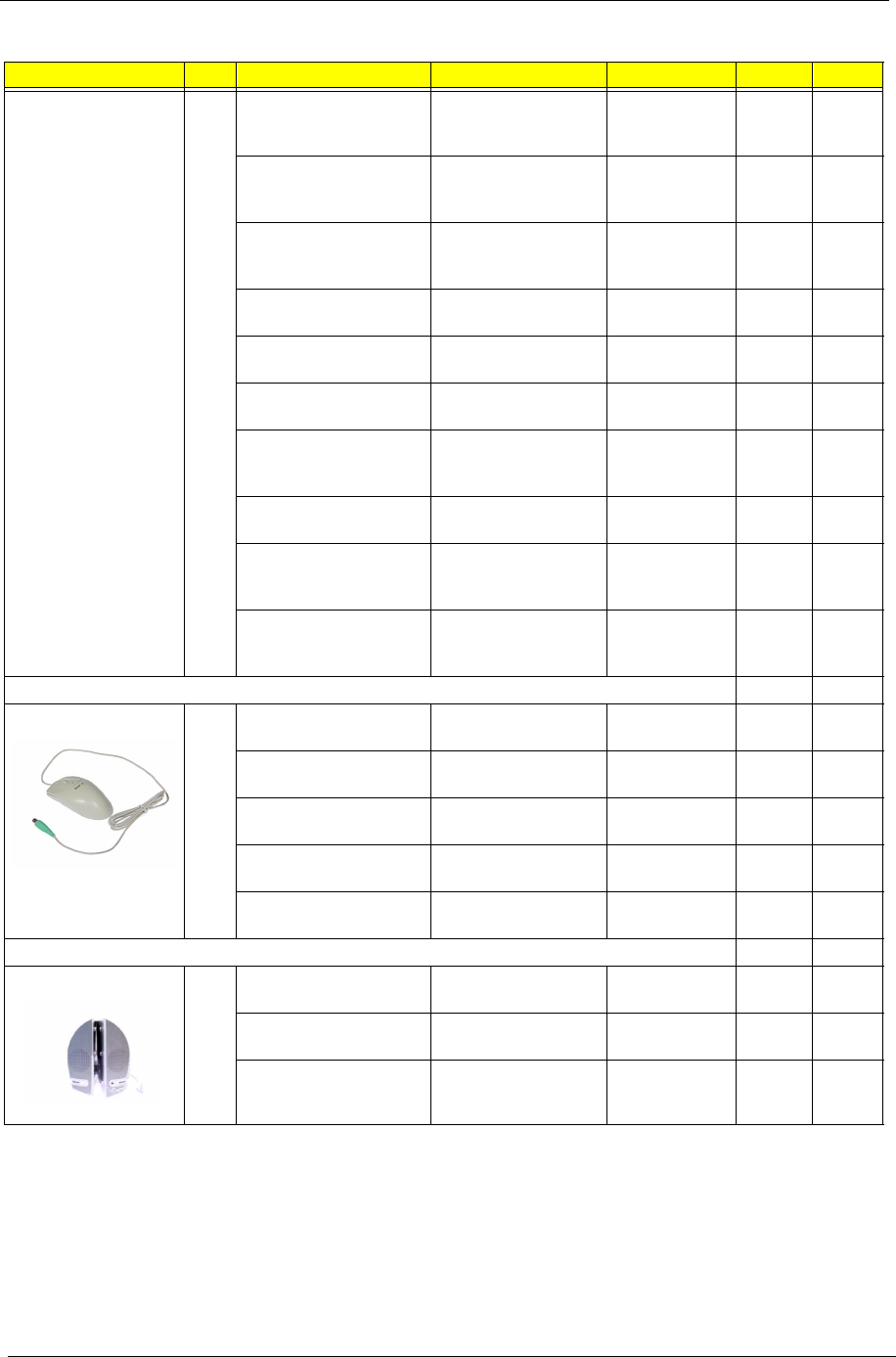
96 Chapter 6
KEYBOARD 105KEYS
PORTUGUESE PS/2
DARFON
KB 105KEYS
PORTUGUESE
91.62C07.04P X X
KEYBOARD 105KEYS
TURKEY-F PS/2
DARFON
KB 105KEYS
TURKEY-F 6512-
CX4Q
91.62C07.04Q X X
KEYBOARD 104KEYS
RUSSIAN/US PS/2
DARFON
KB 104KEYS
RUSSIAN/US
91.62C07.04R X X
KEYBOARD 105KEYS
SPANISH PS/2 DARFON
KB 105KEYS
SPANISH
91.62C07.04S X X
KEYBOARD 105KEYS
TURKEY PS/2 DARFON
KB 105KEYS TURKEY
6512-CX4T
91.62C07.04T X X
KEYBOARD 105KEYS
UK PS/2 DARFON
KB 105KEYS UK 6512-
CX4U
91.62C07.04U X X
KEYBOARD 105KEYS
CANDIAN/FRENCH PS/2
DARFON
KB 105KEYS
CANDIAN/FRENCH
91.62C07.04V X X
KEYBOARD 105KEYS
SWEDEN PS/2 DARFON
KB 105KEYS
SWEDEN 6512-CX4W
91.62C07.04W X X
KEYBOARD 105KEYS
HUNGARIA/US PS/2
DARFON
KB 105KEYS
HUNGARIA/US
91.62C07.04X X X
KEYBOARD 104KEYS
GREEK/US PS/2
DARFON
KB 104KEYS GREEK/
US 6511-CX4Y
91.62C07.04Y X X
Pointing device
NS MOUSE
,USB,LOGITECH U48A
MOUSE LOGITECH
U48A/D002 V75M
90.37C26.005 X X
MOUSE,PS/2,PRIMAX/
MOSXK
MOUSE PS/2 3D
PRIMAX/MOSXK
90.37C26.003 X X
MOUSE ,PS/
2,LOGITECH /S42
MOUSE LOGITECH 2
BUTTON/S42
90.00026.915 X X
MOUSE,PS/
2,LOGITECH/S48A
MOUSE WHEEL
LOGITECH/S48A S61
90.35G26.001 X X
MOUSE,PS/2,PRIMAX/
MUSXJ
MOUSE 2 BOTTON
PRIMAX/MUSXJ
90.00026.067 X X
Speaker
NS SPEAKER,USB,CHARMI
NG/V-1
SPK USB POWER
CHARMING/V-1
90.38H12.001 X X
SPEAKER,USB,CHARMI
NG/HIPS
SPK USB LOW COST
CHARMING/HIPS
90.37C12.019 X X
SPEAKER,USB,CHARM/
KT-691YB
SPK USB PWR
CHARM/KT-691YB
90.37C12.017 X X
Picture No. Partname Description Part No. 5100 7100

Appendix A 97
Veriton 5100
The Veriton 5100 Model No. Define:
1. Trade Mark:
2. Brand Name: Acer
3. Description: Acer Veriton Series, PIII & Celeron Socket 370 Based PC System
4. Model No: VT5100
5. Product Name: Veriton 5100
Model Definition and Configuration
Appendix A

98 Appendix A
Veriton 7100
The Veriton 7100 Model No. Define:
1. Trade Mark:
2. Brand Name: Acer
3. Description: Acer Veriton Series, PIII & Celeron Socket 370 Based PC System
4. Model No: VT7100
5. Product Name: Veriton 7100

Appendix B 99
This computer’s compatibility is tested and verified by Acer’s internal testing department. All of its system
functions are tested under MS DOS V6.22, Microsoft Windows 98 SE (EN/TW), Microsoft Windows 2000
Professional, Microsoft Win95/NT 4.0 Workstation, IBM OS/2 Warp 4.0, Novell Netware 4.12 & 5.1, and SCO
UNIX/Red Hat Linux environment.
Refer to the following lists for components, adapter cards, and peripherals which have passed these tests.
Regarding configuration, combination and test procedures, please refer to the Veriton 5100/7100 Compatibility
Test Report released by the Acer Desktop System Testing Department.
Test Compatible Components
Appendix B

100 Appendix B
MS DOS V6.22 Environment Test
Item Specifications
Processor Coppermine 500/66 MHz
Coppermine 600/100 MHz
Coppermine 667/133 MHz
Coppermine 800/133 MHz
Memory 64 MB
128 MB
192 MB
256 MB
Cache 128 KB
256 KB
Diskette Drive Panasonic JU-256A
EIDE Channel 1 Master Seagate 20.4 GB
API 650P
EIDE Channel 1 Slave Maxtor 30 GB
AOpen CD-948E
EIDE Channel 2 Master API 640A-247
Quamtum 20.4 GB
EIDE Channel 2 Slave AOpen CD-940E Pro
Seagate 10.2 GB
Mouse Logitech Wheel Mouse S48A
Primax Wheel Mouse MOSXK
Keyboard API 62C
API 32TW
Monitor Acer View 19”
Acer View 77C
LAN Adapter Acer NIC-559 With AOL II
ANI ALN-325
3COM 3C905C-TXM

Appendix B 101
Microsoft Windows 98SE (EN/TW) Environment Test
Item Specifications
Processor Coppermine 600/66 MHz
Coppermine 700/100 MHz
Coppermine 733/133 MHz
Coppermine 866/133 MHz
Memory 64 MB
128 MB
192 MB
256 MB
Cache 128 KB
256 KB
Floppy Disk Drive Panasonic JU-256A
EIDE Channel 1 Master Seagate 20.4 GB
Quantum 15 GB
API 650P
EIDE Channel 1 Slave Maxtor 30 GB
Quantum 10.2 GB
AOpen CD-948E
EIDE Channel 2 Master Quantum 20.4 GB
Maxtor 10.2 GB
API 640A-247
EIDE Channel 2 Slave AOpen CD-940E Pro
Seagate 10.2 GB
Mouse Logitech Wheel Mouse S48A
Primax Wheel USB
Keyboard API 62C
API USB
Monitor Acer View 19”
Acer View 77C
Sound/MPEG Adapter Onboard AD1881
Diamond Monster Sound M80 PCI Card
Creative Sound Blaster PCI 64
Video Adapter Winfast 3D S325 32 MB PCI
ATI 128 PRO Pro 16 MB PCI
ATI 128 PRO Pro 32 MB PCI
LAN Adapter Acer NIC-559A
3COM 3C905C-TXM
ANI ALN-325
IBM Token Ring PCI
Fax/Modem Adapter Ambit 56K HCF PCI
Askey 56K HCF PCI
CIS Rockwell HCF PCI
Etech 56K Data/Fax/Voice Modem
Joystick/Game Pad Microsoft SideWinder Precision Pro
Microsoft SideWinder Force Feedback Pro
Microsoft SideWinder Game Pad
Primax RAPTOR 3D USB Gamestick

102 Appendix B
USB Devices HP Desk Jet 895C USB Printer
Logitech Pagescan USB
Acer Digital Video Camera
Primax USB Joystick
Microsoft USB Joystick
AcerScan Prisa 310U
USB Altec Lansing Speaker
Intel USB Digital Video Camera
Printer HP Desk Jet 695C
Epson Stylus Color 440
Canon BJC-4130 SP
Brother HL-660 6PPM Laser Printer
Item Specifications
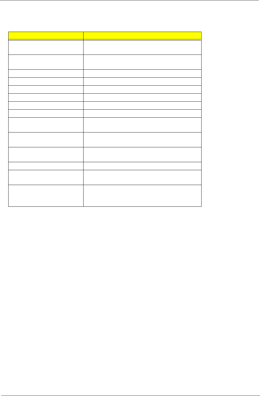
Appendix B 103
Microsoft Windows 2000 Professional Environment Test
Item Specifications
Processor Coppermine 600/133 MHz
Coppermine 650/100 MHz
Memory 64 MB
256 MB
Cache 256 KB
Diskette Drive Panasonic JU-256A
EIDE Channel 1 Master Seagate 30 GB
EIDE Channel 1 Slave Quantum 20.4 GB
EIDE Channel 2 Master API 640A-247
EIDE Channel 2 Slave AOpen CD-940E Pro
Mouse Logitech Wheel Mouse S48A
Primax Wheel Mouse MOSXK
Keyboard API 62C
API 32TW
Monitor Acer View 19”
Acer View 77C
Sound Adapter Onboard AD1881
Video Adapter ATI Rage 128 PRO 32MB PCI
Acer TNT2 AGP 4X 16MB PCI
LAN Adapter 3COM 3C905C-TXM
ANI ALN-325
Acer NIC-559A

104 Appendix B
Microsoft Win95/NT 4.0 Workstation Environment Test
Item Specifications
Processor Coppermine 500/100 MHz
Coppermine 866/133 MHz
Memory 64 MB
256 MB
Cache 256 KB
Diskette Drive Panasonic Ju-256A
EIDE Channel 1 Master Seagate 20 GB
EIDE Channel 1 Slave Quantum 20.4 GB
EIDE Channel 2 Master API 640A-247
EIDE Channel 2 Slave AOpen CD-940E Pro
Mouse Logitech Wheel Mouse S48A
Primax Wheel Mouse MOSXK
Keyboard API 62C
API 32TW
Monitor Acer View 19”
Acer View 77C

Appendix B 105
IBM OS/2 Warp 4.0 Environment Test
Item Specifications
Processor Coppermine 600/100 MHz
Memory 256 MB
Cache 256 K
Diskette Drive Panasonic JU-256A
EIDE Channel 1 Master Seagate 20.4 GB
EIDE Channel 2 Master API 640A-247
Mouse Logitech Wheel Mouse S48A
Keyboard API 62C
Monitor Acer View 19”

106 Appendix B
Novell Netware 4.12 & 5.1 Environment Test
Item Specifications
Processor Coppermine 500/66 MHz
Coppermine 600/100 MHz
Coppermine 800/133 MHz
Coppermine 866/2133 MHz
Memory 64 MB
96 MB
128 MB
256 MB
Cache 128 KB
256 KB
Diskette Drive Panasonic JU-256A
EIDE Channel 1 Master Seagate 30 GB
EIDE Channel 1 Slave Quantum 20.4 GB
EIDE Channel 2 Master API 640A-247
EIDE Channel 2 Slave AOpen CD-940E Pro
Mouse Logitech Wheel Mouse S48A
Primax Wheel Mouse MOSXK
Keyboard API 62C
API 32TW
Monitor Acer View 19”
Acer Vew 77C
LAN Adapter 1 3COM 3C905C-TXM
Acer NIC-559A
ANI ALN-325
LAN Adapter 2 3COM 3C339
3COM 3C905C-TXM
D-Link DFE-500TX
IBM Token Ring PCI
LAN Adapter 3 ANI ALN-325
IBM Token Ring PCI
3COM 3C339
3C905C-TXM
SCSI Adapter AHA-2940UW
AHA-3940UW
AHA-3940AUW
SCSI HDD Seagate 8 GB
IBM 4 GB
Quantum 2 GB

Appendix B 107
SCO UNIX/Red Hat Linux Environment Test
Item Specifications
Processor Coppermine 500/100 MHz
Coppermine 866/133 MHz
Memory 64 MB
256 MB
Cache 256 KB
Diskette Drive Panasonic JU-256A
EIDE Channel 1 Master Seagate 30 GB
EIDE Channel 1 Slave Quantum 20.4 GB
EIDE Channel 2 Master API 640A-247
EIDE Channel 2 Slave AOpen CD-940E Pro
Mouse Logitech Wheel Mouse S48A
Primax Wheel Mouse MOSXK
Keyboard API 62C
API 32TW
Monitor Acer View 19”
Acer View 77C

108 Appendix B

Appendix C 109
This appendix describes online technical support services available to help you repair your Acer Systems.
If you are a distributor, dealer, ASP or TPM, please refer your technical queries to your local Acer branch
office. Acer Branch Offices, Regional Offices and Regional Group may access our website. However, some
information sources will require a user I.D. and password. These can be obtained directly from Acer CSD
Taiwan.
Acer's Website offers you convenient and valuable support resources whenever you need them.
You can get the information on all of Acer's Notebook, Desktop and Server models including;
!Service guides for all models
!User's manuals
!Training materials
!BIOS updates
!Software utilities
Also contained on this website are:
!Detailed information on Acer's International Traveler's Warranty (ITW)
!An overview of all the support services we offer, accompanied by a list of telephone, fax and e-mail
contacts for all your technical queries.
Here is the Acer headquarters’ Customer Service Division Internet address for your support information:
http://csd.acer.com.tw
If you have any suggestions or comments, please do not hesitate to communicate these to:
GCSDlifeline@acer.com.tw, or fax to (886) 2 86911799.
Appendix C
Online Support Information

110 Appendix C

Index 111
A
Advanced Options 47
PnP/PCI 49
AGP
removing 68
AGP Expansion Cards 61
Assignment Map 21
Audio
controller 19
Audio Board 84
Audio Interface 19
Audio-in/Line-in port 7, 11
Audio-out/Line-out port 7, 11
B
Basic level 28
BIOS Setup 27
Entering Setup 28
Setup Utility 28
BIOS Utility 50
Abort Settings Change 53
Advanced Options 47
Boot Options 41
Date 43
Disk Drives 33
Exiting Setup 54
Load Default Settings 52
Memory/Cache Options 47
Onboard Peripherals 37
PnP/PCI Options 49
Power Management 39
Product Information 32
System Security 44
Time 43
Boot Options 41
boot sequence 41
fast boot 41
memory test 42
Num Lock after boot 42
silent boot 41
C
Cache Memory 17
scheme 17
size 17
speed 17
type 17
voltage 17
CD-ROM Drive
removing 67
Chipset Settings 50
System Utilities 50
Chipsets 23
CMOS Setup 27
Compatibility Test 99
Connectors 81
Description 82
description 82
controllers 23
audio 19
serial port 20
video 18
CPU
removing 57, 58, 65
CPU upgrade
removing 57, 58, 65
CRT Monitor port 7, 11
Current 24
D
Date 43
Device Standby Mode 25
Dimensions 23
disassembly
CD-ROM Drive 60
Power Supply 62
Disk Drives 33
cylinder 36
DMA transfer mode 36
floppy drives A/B 33
Hard disk 32-bit access 36
Hard disk block mode 36
head 36
IDE primary channel master 33
IDE primary channel slave 33
IDE secondary channel master 33
IDE secondary channel slave 33
sector 36
size 36
type 35
Diskette Drive
removing 66
Index

112 Index
DRQ Assignment Map 23
E
ECP 20
Environmental Requirements 23
EPP 20
Error Codes 75
Error Sysmptoms List 75
Expansion Cards
removing 68
Expansion slot 7, 11
F
features 2
connectivity 2
design 3
ergonomics 3
Multimedia 2
Performance 2
Floppy disk drive Interface 19
Frequency 24
front panel 8
FRU 85
G
Game/MIDI port 7, 10
Global Standby Mode 25
Graphics Aperture Size 50
H
Hard Disk
removing 66
Hard Disk Drive 59
Hardware Specifications and Configurations 16
HDD
removing 66
Housing 63
Opening the 63
Humidity 23
I
I/O Address Map 22
IDE Interface 19
IDSEL 21
Interface
audio 19
IDE 19
Video 18
IRQ Assignment Map 22
IRQ Sharing 49
J
Jumper and Connector Information 81
Jumpers 81
K
keyboard 13
cursor keys 14
lock keys 14
windows-keys 15
L
Load Default Settings 52
M
Machine Disassembly 55
cover 63
Housing Cover 63
Main board 81
removing 70
Main Board Layout 12
Mechanical Specifications 23
Memory
removing 64
size 17
system 17
Memory Address Map 21
Memory/Cache Options 47
external cache 47
internal cache 47
Model Definition 97
Modem 20
data 20
fax 20
voice 20
Motherboard
removing 70
MPU-401 19
N
Netware 3.12, 4.11 & 5.0 Environment Test 106
Network port 10
NT 4.0 Environment Test 104
O
Onboard Peripherals 37
base address 37
ECP DMA channel 37
IRQ 37

Index 113
operation mode 37
serial port 1/2 37
Online Support Information 109
Overview 1
P
Parallel Port 20
Parallel/printer port 7, 10
Password
bypassing 46
changing 46
removing 46
setting 45
Setup 44
PCI
removing 68
PCI Expansion Cards 61
PCI INTx# 21
PCI Slot IRQ 21
ports
left panel 10
POST 72
Power button 5, 8
Power cord socket 7, 10
Power LED 5, 8
Power Management 25, 39
IDE hard disk timer 39
modem ring indicator 40
modes 39
power switch > 4 seconds 40
Sleep mode 39
system sleep timer 39
system wake-up event 40
Power Supply
removing 70
Power-On Self-Test (POST) 72
Processor 57, 58, 65
removing 57, 58, 65
Product Information 32
DMI BIOS version 32
main board ID 32
product name 32
system BIOS version 32
system serial number 32
PS/2 keyboard port 7, 10
PS/2 mouse port 7, 10
R
Removal and Replacement 55
removing 57, 58, 65
Replacement
Assembly, Machine 55
replacing HDD 59
RIMM
Removing 56, 64
RMA 85
Routing Map 21
S
SCO UNIX/Linux Environment Test 107
Security 44
disk drive control 44
floppy drive 44
hard disk drive 44
Setup password 44
Serial Port 20
Serial port 7, 11
socket
memory 17
Socket 370 16
Suspend Mode 25
Switching
Power Supply 102W 24
Symptoms List 75
Audio 77
CD/DVD-ROM Drive 76
Diskette Drive 75
Keyboard 78
Memory 75
Modem 77
Monitor 77
Other 78
Parallel Port 78
Power Supply 78
Processor / Processor Fan 75
Real-Time Clock 77
Serial Port 78
System Board 75
Video 77
System 27
System Board
removing 70
System Information
1st bank 31
2nd bank 31
External cache size 30
Floppy drive A 30
Floppy drive B 30
IDE primary channel master 30
IDE primary channel slave 30
IDE secondary channel master 31
IDE secondary slave 31
Internal cache size 30
parallel port 31
Processor 30

114 Index
Processor speed 30
PS/2 mouse 31
serial port 1 31
total memory 31
System Memory 56, 64
System Security
Power-on password 44
System Specifications 1
design 3
Features 2
System Utilities 27
Abort Settings Change 53
Advanced Options 47
Boot Options 41
Date 43
Disk Drives 33
Exiting Setup 54
Load Default Settings 52
Memory/Cache Options 47
Onboard Peripherals 37
PnP/PCI Options 49
Power Management 39
Product Information 32
System Security 44
Time 43
T
Temperature 23
Test Compatible Components 99
Time 43
Troubleshooting 71
U
UART 20
Undetermined Problems 79
Universal HCI 20
USB Port 20
USB ports 7, 10
V
VGA Palette Snoop 49
Vibration 23
video
controller 18
Video controller 18
Voltage 24
Voltage selector switch 7, 11
W
Weight 23
Win95/Win2000 Environment Test 103
Windows 98 Environment Test 101
