Aclara Power Line Systems Y72129-1 Electronic Metering Transceiver User Manual RF
Aclara Power-Line Systems Inc. Electronic Metering Transceiver RF
UserManual.wiki
>
Aclara Power Line Systems
>
Y72129 1 User Manual
users manual
Navigation menu
Upload a User Manual
Namespaces
Wiki Guide
HTML
PDF
Info
Views
User Manual
Discussion / Help
Navigation
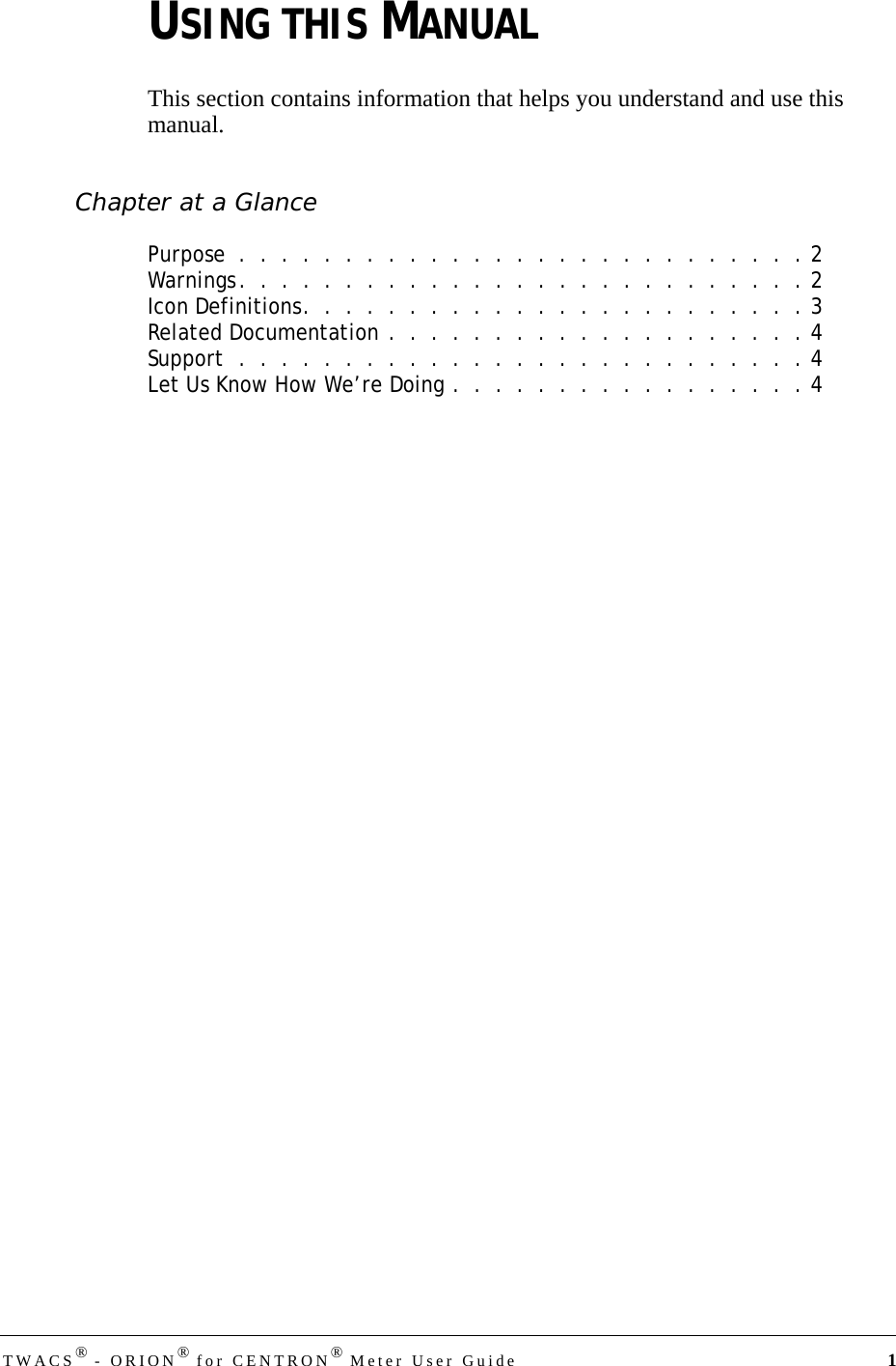
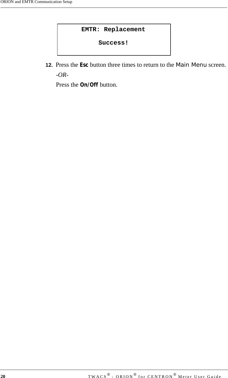
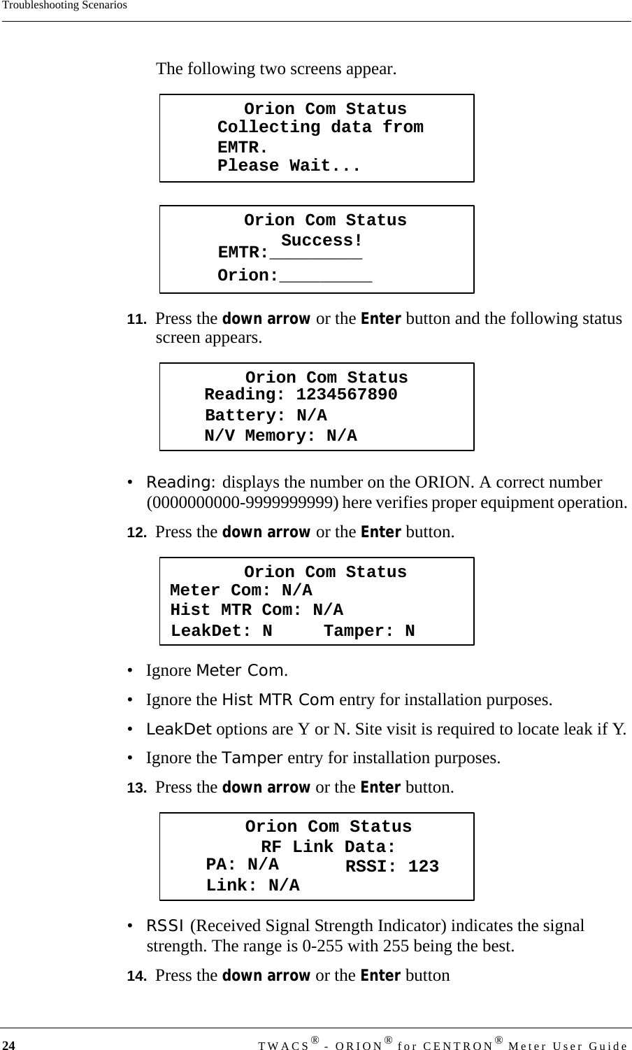
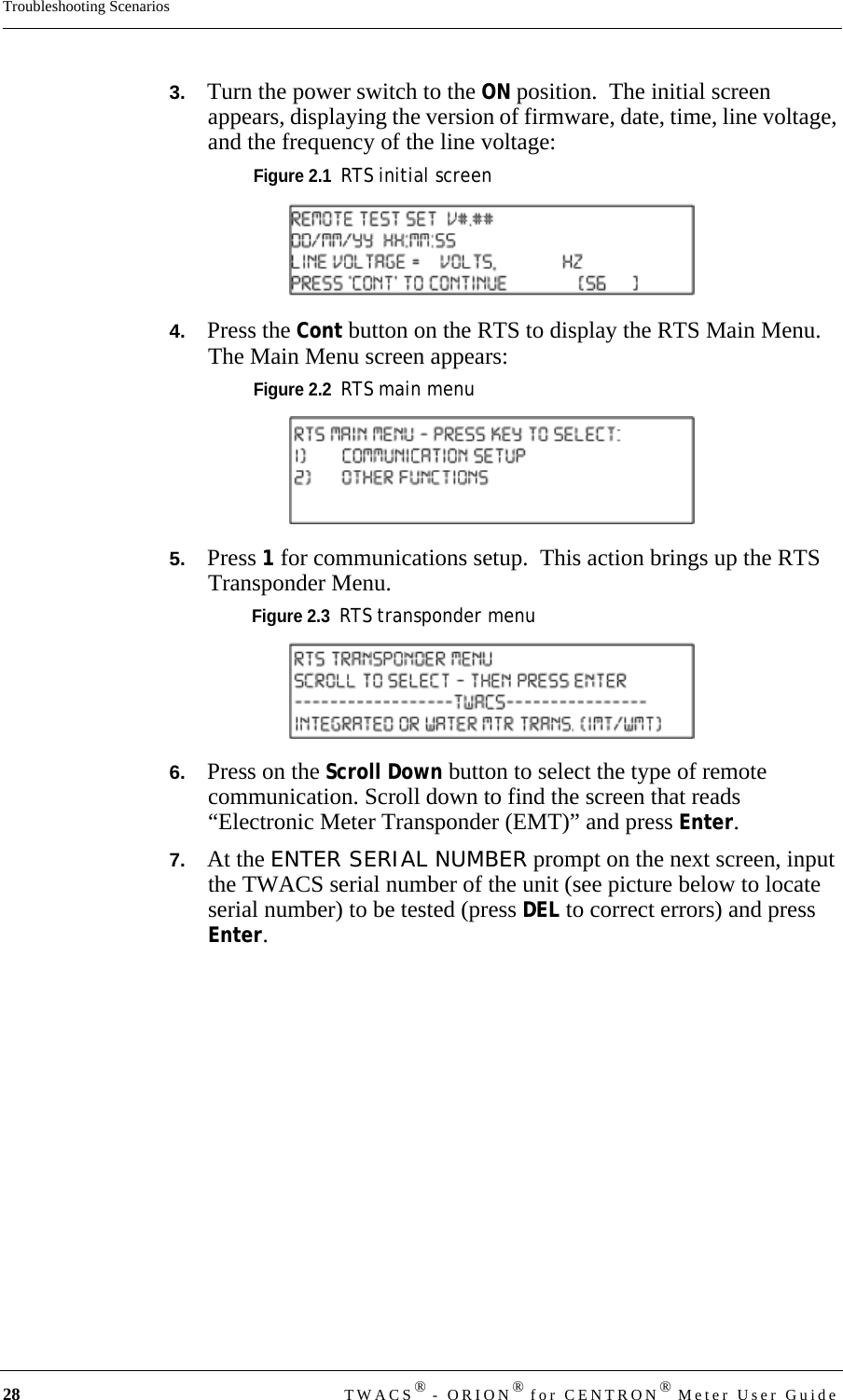
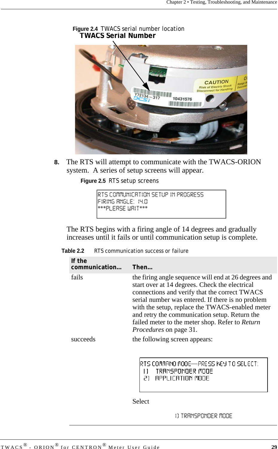
![TWACS® - ORION® for CENTRON® Meter User Guide 3Installation and OperationTheory of OperationThe DCSI TWACS® - ORION® system operates within the 916.450 MHz UHF radio frequency range on channel 43A. This unlicensed frequency band is known as the ISM (Industrial, Science, and Medical) band. All components in the DCSI TWACS® - ORION®system comply with FCC (Federal Communications Commission) rules and regulations for radio devices operating in this frequency range.This band provides up to 79 channels; the TWACS® - ORION®system uses 51 of these channels. A channel is defined as a pair of adjacent frequencies used for transmission and for reception. Refer to the note below.Because the FCC limits the amount and duration of channel energy that can be emitted during RF transmission, the TWACS® - ORION® system employs transmission Frequency Shift Keying (FSK). This modulation and frequency hopping technology serves to: • Comply with FCC regulations• Reduce potential interference to and from other devices operating in the same band• Reduce the potential for eavesdropping• Minimize the effects of signal reduction NOTEFrequency hopping employs an algorithm that provides a half duplex (one transmission direction at a time [send or receive]), pseudo-random sequence of frequencies for the two-way radio link. Frequency Shift Keying modulation controls data transmission by “frequency shifting” between two frequencies (a channel). One frequency is used to represent the logical “1” and a different frequency represents the logical “0”.Five channels provide link acquisition with the HHTR while the remaining 45 channels are used for data transmission after a successful link is established. The one remaining channel is used for TWACS-ORION communication.The EMTR retains data until new data is uploaded during an ORION session. If an ORION transmitter is removed from the Remt List table stored in the EMTR, the previously loaded data (for the removed ORION transmitter) is automatically deleted.](https://usermanual.wiki/Aclara-Power-Line-Systems/Y72129-1/User-Guide-616200-Page-15.png)