Aclara Power Line Systems Y72129-1 Electronic Metering Transceiver User Manual RF
Aclara Power-Line Systems Inc. Electronic Metering Transceiver RF
users manual
TWACS - ORION FOR CENTRON METER
USER GUIDE Y10426-TUM
RRR

TWACS® - ORION® for CENTRON® Meter User Guide (Y10426-TUM)
Proprietary Notice
Information contained in this document is private to Distribution Control Systems, Inc., St. Louis,
Missouri (DCSI). This information may not be published, reproduced, or otherwise disseminated without
the express written authorization of DCSI.
Any software or firmware described in this document is furnished under a license and may be used or
copied only in accordance with the terms of such license.
Disclaimer
The information in this document is subject to change without notice and should not be construed as a
commitment by DCSI. DCSI assumes no responsibility for any errors that may appear in this document.
No responsibility is assumed for the use or reliability of software on equipment that is not supplied by
DCSI.
TWACS, the TWACS logo, and the DCSI logo are registered trademarks of Distribution Control Systems,
Inc., St. Louis, Mo.
TWACS®
Two-Way Automatic Communication System,
a product of
Distribution Control Systems, Inc.
Confidential and Proprietary
Copyright 2005 All Rights Reserved

TWACS® - ORION® for CENTRON® Meter User Guide i
Figures and Tables iii
Using this Manual 1
Purpose . . . . . . . . . . . . . . . . . . . . . . . . . . . . . . . . . 2
Warnings . . . . . . . . . . . . . . . . . . . . . . . . . . . . . . . . . 2
Icon Definitions . . . . . . . . . . . . . . . . . . . . . . . . . . . . . . 3
Related Documentation . . . . . . . . . . . . . . . . . . . . . . . . . . 4
Support . . . . . . . . . . . . . . . . . . . . . . . . . . . . . . . . . 4
Let Us Know How We’re Doing . . . . . . . . . . . . . . . . . . . . . . . 4
Chapter 1: Installation and Operation 1
System Overview . . . . . . . . . . . . . . . . . . . . . . . . . . . . . 2
Theory of Operation. . . . . . . . . . . . . . . . . . . . . . . . . . . . 3
Electric Meter Transceiver (EMTR) . . . . . . . . . . . . . . . . . . . . . 4
RF TWACS and Badger Meter, Inc. ORION® Transmitter . . . . . . . . . . . 5
Hand Held Transceiver (HHTR) . . . . . . . . . . . . . . . . . . . . . . 6
Navigating the HHTR Screens . . . . . . . . . . . . . . . . . . . . . . 7
HHTR Menus. . . . . . . . . . . . . . . . . . . . . . . . . . . . . . 7
RF Hardware Installation. . . . . . . . . . . . . . . . . . . . . . . . . . 9
Pre-Installation Field Survey . . . . . . . . . . . . . . . . . . . . . . . 9
Environmental Conditions . . . . . . . . . . . . . . . . . . . . . . . 9
Installing a New EMTR Module. . . . . . . . . . . . . . . . . . . . . . 11
ORION Equipment Installation . . . . . . . . . . . . . . . . . . . . . . 12
Installing a Replacement EMTR Module. . . . . . . . . . . . . . . . . . 12
ORION Equipment Replacement . . . . . . . . . . . . . . . . . . . . . 12
ORION and EMTR Communication Setup . . . . . . . . . . . . . . . . . . 13
Install the ORION (Linking the ORION and EMTR) . . . . . . . . . . . . . 13
Delete the ORION from the Remt List . . . . . . . . . . . . . . . . . . 15
Replace the EMTR . . . . . . . . . . . . . . . . . . . . . . . . . . . 17
Chapter 2: Testing, Troubleshooting, and Maintenance 21
Troubleshooting and Error Messages. . . . . . . . . . . . . . . . . . . . 22
Troubleshooting Scenarios . . . . . . . . . . . . . . . . . . . . . . . . 22
Configuration/Installation Status . . . . . . . . . . . . . . . . . . . . 22
Field Troubleshooting. . . . . . . . . . . . . . . . . . . . . . . . . . 25
HHTR Displayed Error Codes . . . . . . . . . . . . . . . . . . . . . 26
Remote Test Set (RTS) . . . . . . . . . . . . . . . . . . . . . . . . 27
Meter Shop Test System . . . . . . . . . . . . . . . . . . . . . . . . . 30
Maintenance . . . . . . . . . . . . . . . . . . . . . . . . . . . . . . 30
Warranty . . . . . . . . . . . . . . . . . . . . . . . . . . . . . . . . 30
Return Procedures. . . . . . . . . . . . . . . . . . . . . . . . . . . . 31
Chapter 3: Specifications 33
Electrical Specifications . . . . . . . . . . . . . . . . . . . . . . . . . 34
Electrical Ratings . . . . . . . . . . . . . . . . . . . . . . . . . . . 34
Compliance Specifications . . . . . . . . . . . . . . . . . . . . . . . 34
Environmental Specifications. . . . . . . . . . . . . . . . . . . . . . . 35
Table of Contents


TWACS® - ORION® for CENTRON® Meter User Guide iii
Figure 1.1 Electric Meter Transceiver . . . . . . . . . . . . . . . . . . . . . . . . . . . . 4
Figure 1.2 ORION transmitters for water, gas, and remote . . . . . . . . . . . . . . 5
Table 1.1 ORION transmitter specifications. . . . . . . . . . . . . . . . . . . . . . . . 5
Figure 1.3 Hand Held Transceiver keypad functions. . . . . . . . . . . . . . . . . . . 6
Table 0.1 Error Code Description and Solution. . . . . . . . . . . . . . . . . . . . . 26
Figure 2.1 RTS initial screen . . . . . . . . . . . . . . . . . . . . . . . . . . . . . . . . . 28
Figure 2.2 RTS main menu . . . . . . . . . . . . . . . . . . . . . . . . . . . . . . . . . . 28
Figure 2.3 RTS transponder menu . . . . . . . . . . . . . . . . . . . . . . . . . . . . . 28
Figure 2.4 TWACS serial number location . . . . . . . . . . . . . . . . . . . . . . . . 29
Figure 2.5 RTS setup screens. . . . . . . . . . . . . . . . . . . . . . . . . . . . . . . . . 29
Table 2.2 RTS communication success or failure . . . . . . . . . . . . . . . . . . . 29
Figure 2.6 Return address Label . . . . . . . . . . . . . . . . . . . . . . . . . . . . . . 32
Table 3.1 Electrical ratings . . . . . . . . . . . . . . . . . . . . . . . . . . . . . . . . . 34
Table 3.2 Compliance specifications . . . . . . . . . . . . . . . . . . . . . . . . . . . 34
Table 3.3 Environmental specifications . . . . . . . . . . . . . . . . . . . . . . . . . 35
Table 3.4 Physical specifications. . . . . . . . . . . . . . . . . . . . . . . . . . . . . . 35
Table 3.5 Labeling requirements. . . . . . . . . . . . . . . . . . . . . . . . . . . . . . 36
Figures and Tables

iv TWACS® - ORION® for CENTRON® Meter User Guide
Figures and Tables

TWACS® - ORION® for CENTRON® Meter User Guide 1
U
SING
THIS
M
ANUAL
This section contains information that helps you understand and use this
manual.
Chapter at a Glance
Purpose . . . . . . . . . . . . . . . . . . . . . . . . . . . 2
Warnings. . . . . . . . . . . . . . . . . . . . . . . . . . . 2
Icon Definitions. . . . . . . . . . . . . . . . . . . . . . . . 3
Related Documentation . . . . . . . . . . . . . . . . . . . . 4
Support . . . . . . . . . . . . . . . . . . . . . . . . . . . 4
Let Us Know How We’re Doing . . . . . . . . . . . . . . . . . 4
2TWACS® - ORION® for CENTRON® Meter User Guide
Purpose
Purpose
This TWACS® - ORION ®for CENTRON® Meter User Guide contains
theory of operation, pre-installation considerations, hardware installation
procedures, and instructions for using an HHTR tool to establish the
communication link between the ORION and EMTR.
Warnings
TWACS® - ORION® for CENTRON® Meter User Guide 3
Using this Manual
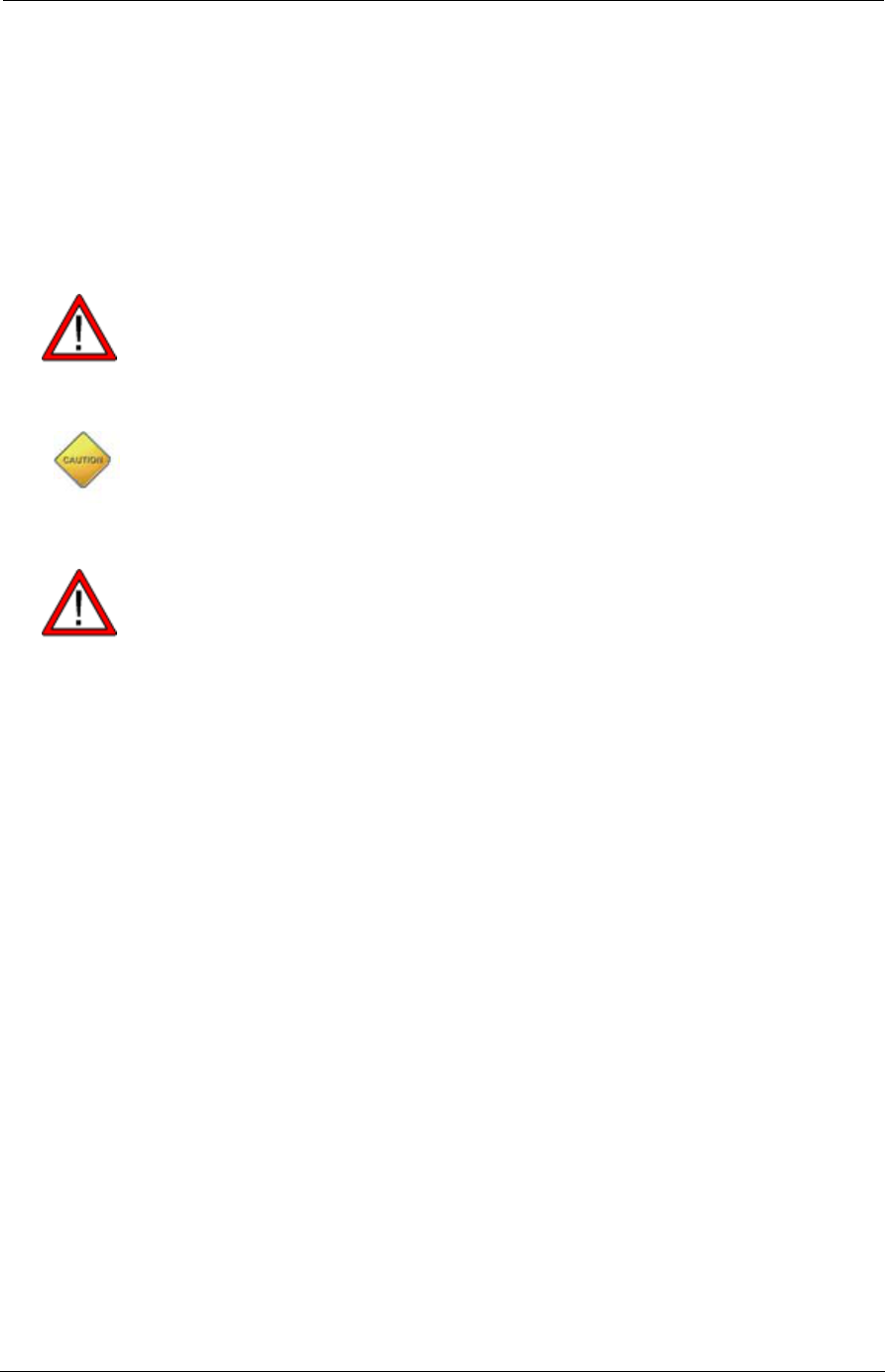
Icon Definitions
Icon Definition
H
AZARD
Indicates electrical equipment hazards and resulting death or
serious injury from misuse.
W
ARNING
Indicates a potentially hazardous situation which - if
precautions are not taken - could result in death or serious
personal injury.
C
AUTION
Indicates a potentially hazardous situation which- if
precautions are not taken - may result in minor or moderate
injury.
I
MPORTANT
Provides information that is important, but will not result in
physical injury if not followed.
N
OTE
Provides additional information or tips on the process.

4TWACS® - ORION® for CENTRON® Meter User Guide
Related Documentation
Related Documentation
The following publications are referenced in this Integrated Metering
Transponder for Electromechanical Meters User Guide. The documents
listed below plus the latest version of all other DCSI technical publications
are available through the TWACS Portal (https://portal.twacs.com/).
• Electronic Metering Transponder for CENTRON Meter User Guide
(Y10317TM)
• TNS End User Guide (Y10285TM)
•Returned Merchandise Packing Requirement Service Advisory
(Y10377TM)
Support
Please address your questions to Customer Care as follows:
Let Us Know How We’re Doing
In an ongoing effort to produce effective documentation, the Technical
Publications department at DCSI welcomes any feedback you can offer
regarding this manual.
Please relay feedback, including suggestions for improvement or to alert us
to corrections, by sending an email to techpubs@twacs.com or calling
Customer Care at 1-800-892-9008.
E-mail: care@twacs.com
Phone: 1-800-892-9008
Address: Distribution Control Systems, Inc.
945 Hornet Drive
Hazelwood, MO 63042
USA

TWACS® - ORION® for CENTRON® Meter User Guide 1
CHAPTER 0CHAPTER
1
C
HAPTER
0
I
NSTALLATION
AND
O
PERATION
This chapter provides a brief overview of the TWACS-ORION system,
explains how the TWACS-ORION system interfaces with the TWACS
system, and describes the functions of the EMTR, HHTR, and ORION
transmitter. It is useful for installers and personnel who would benefit from an
overview of the entire system.
Chapter at a Glance
System Overview . . . . . . . . . . . . . . . . . . . . . . . 2
Theory of Operation . . . . . . . . . . . . . . . . . . . . . 3
Electric Meter Transceiver (EMTR) . . . . . . . . . . . . . . 4
RF TWACS and Badger Meter, Inc. ORION® Transmitter . . . . . 5
Hand Held Transceiver (HHTR) . . . . . . . . . . . . . . . . 6
Navigating the HHTR Screens . . . . . . . . . . . . . . . 7
HHTR Menus . . . . . . . . . . . . . . . . . . . . . . . 7
RF Hardware Installation . . . . . . . . . . . . . . . . . . . 9
Pre-Installation Field Survey. . . . . . . . . . . . . . . . . 9
Environmental Conditions . . . . . . . . . . . . . . . . . 9
Installing a New EMTR Module . . . . . . . . . . . . . . . 11
ORION Equipment Installation . . . . . . . . . . . . . . . 12
Installing a Replacement EMTR Module . . . . . . . . . . . 12
ORION Equipment Replacement . . . . . . . . . . . . . . 12
ORION and EMTR Communication Setup. . . . . . . . . . . . 13
Install the ORION (Linking the ORION and EMTR). . . . . . . 13
Delete the ORION from the Remt List. . . . . . . . . . . . 15
Delete the ORION from the Remt List. . . . . . . . . . . . 15
Replace the EMTR . . . . . . . . . . . . . . . . . . . . 17

2TWACS® - ORION® for CENTRON® Meter User Guide
System Overview
System Overview
The TWACS® - ORION® system utilizes radio frequency (RF)
transmission communication between a RF-enabled auxiliary meter and a
RF-enabled CENTRON® meter. Data relative to energy usage from
auxiliary gas, water, or another electric meter can be gathered and retrieved
in this manner. The system provides selectable Total Consumption data and
Present Consumption data based on the hourly interval meter reading.
Information is retrieved across the Two-Way Automatic Communication
System (TWACS) network by the TWACS Net Server (TNS) located at the
utility company.
The TWACS® - ORION® system solution is comprised of the following RF
devices:
• Electric Meter Transceiver (EMTR)
• Hand Held Transceiver (HHTR)
• Electronic Metering Transponder (EMT-3C-MP)
N
OTE
Also part of the system, but not provided or installed by DCSI, is the
Badger Meter, Inc. ORION transmitter that is installed at the auxiliary
meter and converts the meter information into electronic signals.
RF communication links the ORION (located at the auxiliary meter) to the
EMTR (located inside a nearby electric meter.) This communication
enables successful operation of the Automatic Meter Reading (AMR)
system.
AUXILIARY
METER ELECTRIC
METER
ELECTRIC
METER
TRANSCEIVER
(EMTR)
ORION
TRANSMITTER
RF
COMMUNICATION
UP TO 400 FEET
LINE-OF-SIGHT

TWACS® - ORION® for CENTRON® Meter User Guide 3
Installation and Operation
Theory of Operation
The DCSI TWACS® - ORION® system operates within the 916.450 MHz
UHF radio frequency range on channel 43A. This unlicensed frequency band
is known as the ISM (Industrial, Science, and Medical) band. All components
in the DCSI TWACS® - ORION®system comply with FCC (Federal
Communications Commission) rules and regulations for radio devices
operating in this frequency range.
This band provides up to 79 channels; the TWACS® - ORION®system uses
51 of these channels. A channel is defined as a pair of adjacent frequencies
used for transmission and for reception. Refer to the note below.
Because the FCC limits the amount and duration of channel energy that can
be emitted during RF transmission, the TWACS® - ORION® system employs
transmission Frequency Shift Keying (FSK). This modulation and frequency
hopping technology serves to:
• Comply with FCC regulations
• Reduce potential interference to and from other devices operating in the
same band
• Reduce the potential for eavesdropping
• Minimize the effects of signal reduction
N
OTE
Frequency hopping employs an algorithm that provides a half duplex (one
transmission direction at a time [send or receive]), pseudo-random
sequence of frequencies for the two-way radio link.
Frequency Shift Keying modulation controls data transmission by
“frequency shifting” between two frequencies (a channel). One
frequency is used to represent the logical “1” and a different frequency
represents the logical “0”.
Five channels provide link acquisition with the HHTR while the remaining 45
channels are used for data transmission after a successful link is established.
The one remaining channel is used for TWACS-ORION communication.
The EMTR retains data until new data is uploaded during an ORION session.
If an ORION transmitter is removed from the Remt List table stored in the
EMTR, the previously loaded data (for the removed ORION transmitter) is
automatically deleted.
4TWACS® - ORION® for CENTRON® Meter User Guide
Theory of Operation
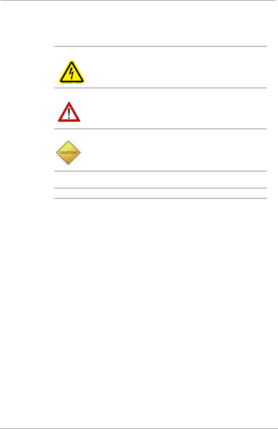
Electric Meter Transceiver (EMTR)
The EMTR is an electronic module assembly (EMA) that is installed in a
TWACS-enabled CENTRON meter. The EMTR is connected to the
EMT-3C-MP transponder during meter/transponder integration. The
EMTR adds functionality to the host EMT-3C-MP. It does not
communicate over the power line, but uploads the data to the EMT-3C-MP
that has power line TWACS capabilities.
The EMTR can communicate with up to four ORION transmitters. Data
from the ORION transmitter is relayed to the EMA. This data is accessed
by the TNS across the TWACS network.
Near the top of the hour, the EMTR listens (for 12.5 seconds) for
communication from an ORION transmitter. Then, for 8.5 seconds the
EMTR listens for an HHTR. This pattern cycles 35 times. No further
communication occurs until the next top of the hour. The top of the hour is
set in TNS. Refer to Metering Maintenance in the TNS User Guide for
instructions.
Figure 1.1
Electric Meter Transceiver
TWACS® - ORION® for CENTRON® Meter User Guide 5
Installation and Operation
RF TWACS and Badger Meter, Inc. ORION
®
Transmitter
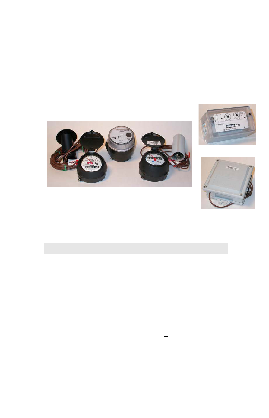
The DCSI RF TWACS System and the Badger Meter, Inc. ORION
transmitter are capable of data communication. The ORION module uses the
RF bubble-up broadcast mode to communicate (one way) from the auxiliary
meter to the electric meter. The ORION transmitter sends customer usage
data (at 100Kbps) every five seconds on the 916.450 MHz frequency channel.
The RF TWACS system receives this data and transmits it to the EMTR.
Then it is retrieved by the utility, across power distribution lines.
Figure 1.2
ORION transmitters for water, gas, and remote
Specifications:
Table 1.1
ORION transmitter specifications
REMOTE
ORION
GAS
ORION
WATER
ORION
ORION
Specification Description
Power 3.6 VDC embedded battery
Functional Life Expectancy Minimum: 10 years
Expected: 15 years
Frequency 916.450 MHz
Data Communications Burst mode fixed length
packet, simplex
Data Format 3-of-6
Data Rate 100 Kbps + 1 Kbps
Data Encryption None
Modulation Frequency Shift Keying (FSK)
Packet Encoding Non Return to Zero (NRZ)
Channels Single channel (43A)
Range 400 ft. clear line of sight -
affected by installation and
conditions; less if pit installed
6TWACS® - ORION® for CENTRON® Meter User Guide
Theory of Operation
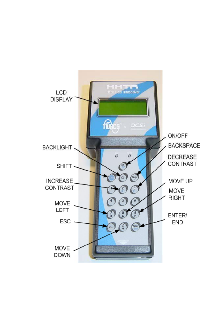
Hand Held Transceiver (HHTR)
The DCSI Hand Held Transceiver (HHTR) is used to configure and setup
the EMTR (installed in the electric meter). The HHTR is also used to create
the communication link between the EMTR and the ORION transmitter
and can be used to test the radio link.
Figure 1.3
Hand Held Transceiver keypad functions
TWACS® - ORION® for CENTRON® Meter User Guide 7
Installation and Operation
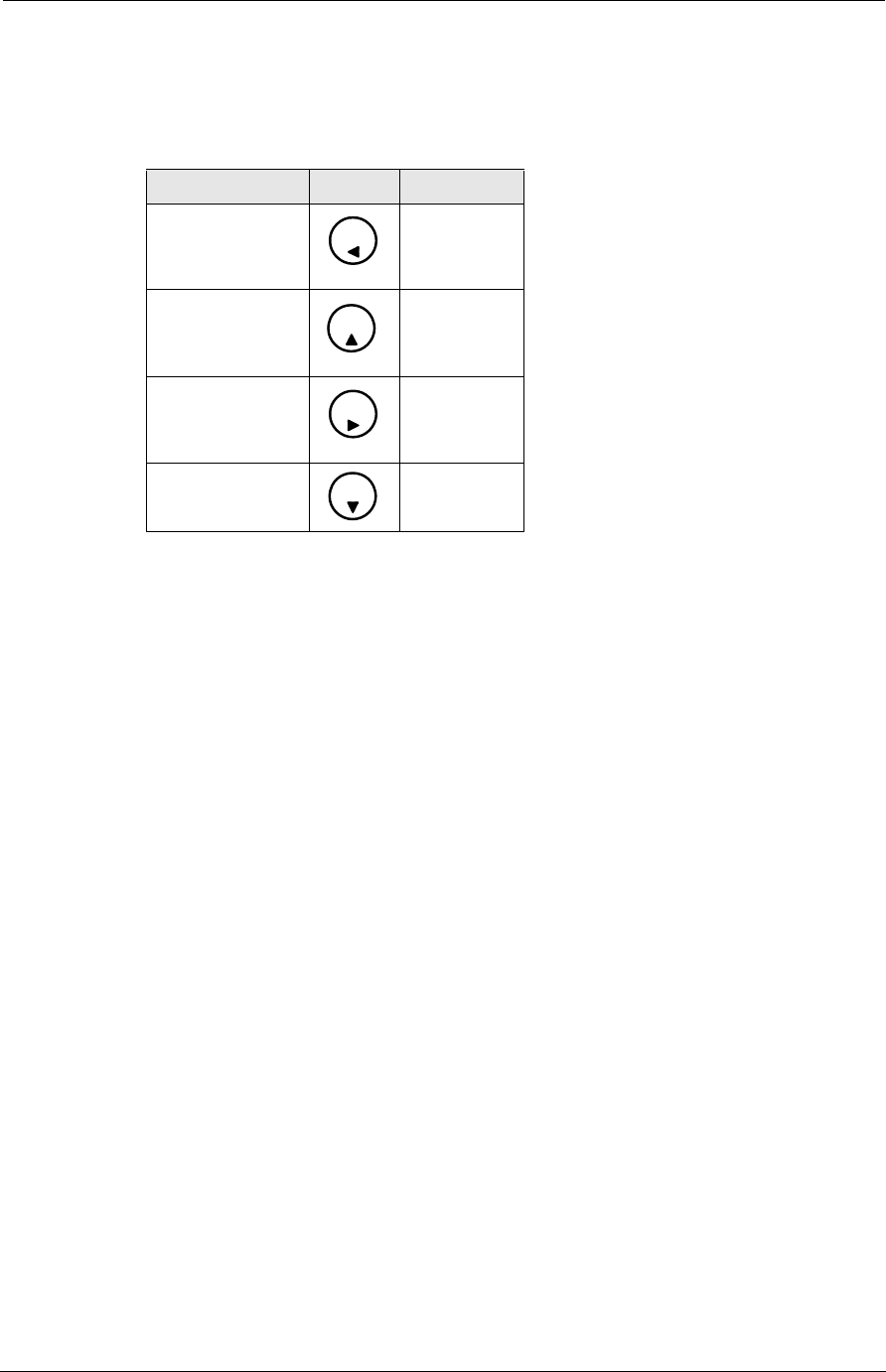
Navigating the HHTR Screens
Use the arrow buttons to navigate through the HHTR screens.
N
OTE
When pressing the 7, 8, 9, or 0 numeric button, the HHTR automatically
determines whether the numeric or scroll functionality of the button is
required.
Adjust the display contrast by using the number 2 and 3 buttons as follows:
• Increase the contrast - Hold down the Shift button and repeatedly press
the number 2 button.
• Decrease the contrast - Hold down the Shift button and repeatedly press
the number 3 button.
Esc button functionality:
• Press once to end the current procedure and return to the previous menu.
• Repeatedly press to “back out” to previous menus.
HHTR Menus
The following list describes the menus and selections available from the
HHTR.
Main Menu Item
Order - Main menu selection.
• New/Go - Presents screens that allow entry of an order number.
Remote - Main menu selection.
• Orion - Top-level Orion menu.
•Install (See page 13).
Table 1.2
HHTR screen navigation buttons
Button Number Graphic Function
7Move left
8 Move up
9 Move right
0 Move down
7
8
9
0

8TWACS® - ORION® for CENTRON® Meter User Guide
Theory of Operation
•Com Stat - Presents configuration status screens (See page 15).This
status information is read from the EMTR.
•RMTR - RMTR menu.
EMTR - Main menu selection.
•Status - Presents EMTR status data screens.
• Replace - Presents screens that enable replacement of the EMTR (See
page 17).
• Delete - Presents screens that enable removal of the ORION from the Remt
List (See page 15).
•Remt List - Displays list of linked ORION transmitters.
Serial Com - Not used.
TWACS - Main menu selection.
•HRTS - Enables configuration of meter auxiliary ports.
• TWACS Modem - Not used.
HHTR Config - Main menu selection.
• Setup - Presents screens that enable selection of HHTR options.
• Status - Not used.
• Power - Presents screens that enable selection of Power options.
• Diags - Presents screens that enable selection of Diagnostic options.

TWACS® - ORION® for CENTRON® Meter User Guide 9
Installation and Operation
RF Hardware Installation
This section provides instructions for installing the RF hardware onsite. A
functioning network can be created and its functionality verified before
leaving the site.
Pre-Installation Field Survey
The field survey is used to review the environmental conditions present at any
particular location and lay out the system to maximize performance. DCSI
recommends that you conduct a field survey before performing the actual
hardware installation.
As with all RF devices, certain environmental conditions must be present to
optimize RF communications. Be aware of the factors that affect the radio
transmission between the ORION and the EMTR when performing the field
survey, such as:
• Metal objects
• Thick walls or foliage
• Local radio interference
• Position of the ORION and/or EMTR
Factor in all environmental conditions when planning the location of the
meter/EMTR assembly.
N
OTE
A clear line of sight between the ORION transmitter and receiver is
preferred, but is not always attainable.
The following section discusses the environmental conditions that may affect
RF transmissions between the ORION and EMTR.
Environmental Conditions
Optimal RF communication between the ORION and the EMTR is affected
by many environmental conditions. Vehicular traffic, parked vehicles in the
signal path, weather conditions, construction, and even the growth of foliage
may affect or degrade RF communication.
Gradual loss of communication from the ORION (caused by an aging battery
for example) can be detected through system checks by the TWACS Net
Server (TNS) Master Station. Persistent loss of communication may indicate
environmental interference and require a site visit to determine the cause.
N
OTE
Sites that continue to experience persistent loss of communication may
require a wired solution to ensure reliable operation.

10 TWACS® - ORION® for CENTRON® Meter User Guide
RF Hardware Installation
The following environmental factors or conditions may affect RF
transmission between the ORION unit and the EMTR located at the electric
meter.
• Metal Objects
Metal objects significantly reduce the strength of the signals reaching
the receiver. Ensure that no metal cladding, cabling, mirrors, water
tanks, refrigerators, pipes, etc. are near the ORION or EMTR. The
straight-line path between both units should be as unobstructed as
possible.
N
OTE
A small, single item, such as a pipe situated half-way between the
transmitter and receiver, is less likely to have any affect on the signal
strength than a larger item(s).
• Thick walls or foliage
Thick walls or foliage between the transmitter and receiver can
reduce the signal strength. Brick, aluminum siding, thick stone walls,
and concrete can impede signal reception.
Avoid dense foliage between the RF units and, when possible,
provide a reserve “growth” clearance to accommodate the growth of
foliage on bushes and trees during spring and summer.
N
OTE
Radio signals can pass more easily through plasterboard walls,
fiberglass, and wood paneling than the previously listed materials.
• Local radio interference
The close proximity of a cell phone mast, a taxi operator's base
station, or large electrical equipment may provide strong radio
interference. The AMR radio devices should be relocated if these
interferences are present.
• Position of the ORION and/or EMTR
These are important factors in RF deployment. The ORION antenna
is omni-directional. The signal radiates 360 degrees. The EMTR
antenna alignment is parallel to the front cover of the electric meter,
and is the most sensitive RF reception surface.
Face the front of the meter/EMTR toward the ORION transmitter
when possible; even on opposite sides of a building. This allows
maximum communication surface and distance between the units.
Allow for some additional power margin in the signal strength to
accommodate seasonal or other changes in environmental conditions.
In the future, after installation, the site owner should inform you of any
alterations to the site that could affect radio performance.
TWACS® - ORION® for CENTRON® Meter User Guide 11
Installation and Operation
Installing a New EMTR Module
This procedure installs an EMTR module by installing an RF-equipped
CENTRON meter.
Technicians must install this equipment in accordance with all National and
Local Code provisions.
W
ARNING
WARNING - EXPLOSIVE HAZARD - Substitution of components may impair
suitability for Class I, Division 2.
C
AUTION
Wear all safety equipment according to your utility rules before opening
the meter base: hard hats, safety face shield, fire retardant clothing,
high voltage rated gloves, safety rated shoes.
W
ARNING
Any work on or near energized meters, meter sockets, or other metering
equipment can present a danger of electrical shock. Such shock could cause
serious injury or death.
To field install a new EMTR-equipped CENTRON meter, refer to the
Electronic Metering Transponder for CENTRON Meter User Guide
(Y10317TM), Chapter 2. Installation.
To complete the installation process, the meter must be configured into the
TNS (refer to the TNS End User Guide for directions). In order to complete
this next step in the installation process, record the location of the meter by
collecting the following information:
• Serial number (required)
•Substation (required)
•Bus
• Feeder
•Phase
• Detection
• Signal
The TNS operator uses this location information to search for the meter. The
more pieces of location information available, the less time TNS will take to
search for the meter.
Refer to the TNS End User Guide for data retrieval instructions.

12 TWACS® - ORION® for CENTRON® Meter User Guide
RF Hardware Installation
ORION Equipment Installation
Follow the Badger Meter, Inc.equipment installation instructions to install
the ORION transmitter.
Installers must install the ORION equipment in accordance with all
National and Local Code provisions.
Installing a Replacement EMTR Module
This procedure is the same as installing a new EMTR-equipped meter
except that previous usage data must be retrieved and ORION/EMTR
linkage information must be reassigned to the replacement EMTR.
1. Refer to Installing a New EMTR Module on page 11 for installation
instructions.
2. Refer to Install the ORION (Linking the ORION and EMTR) on page
13 for linkage assignment instructions.
Refer to the TNS End User Guide for data retrieval instructions
ORION Equipment Replacement
Follow the Badger Meter, Inc.equipment instructions to remove and
replace an existing ORION transmitter.
Installers must perform these procedures in accordance with all
National and Local Code provisions.
TWACS® - ORION® for CENTRON® Meter User Guide 13
Installation and Operation
ORION and EMTR Communication Setup
This section explains the steps required to use the HHTR to configure, link,
and remove/replace an ORION or EMTR.
RF equipment setup procedures consist of configuring the EMTR and making
the RF communication link between the ORION and EMTR. You may also
view the communication statistics, or test the link between the ORION and
EMTR by reading the Total Consumption register for the applicable port and
verifying the reading on the auxiliary meter dials.
Install the ORION (Linking the ORION and EMTR)
Complete the following steps to link the ORION to a nearby EMTR.
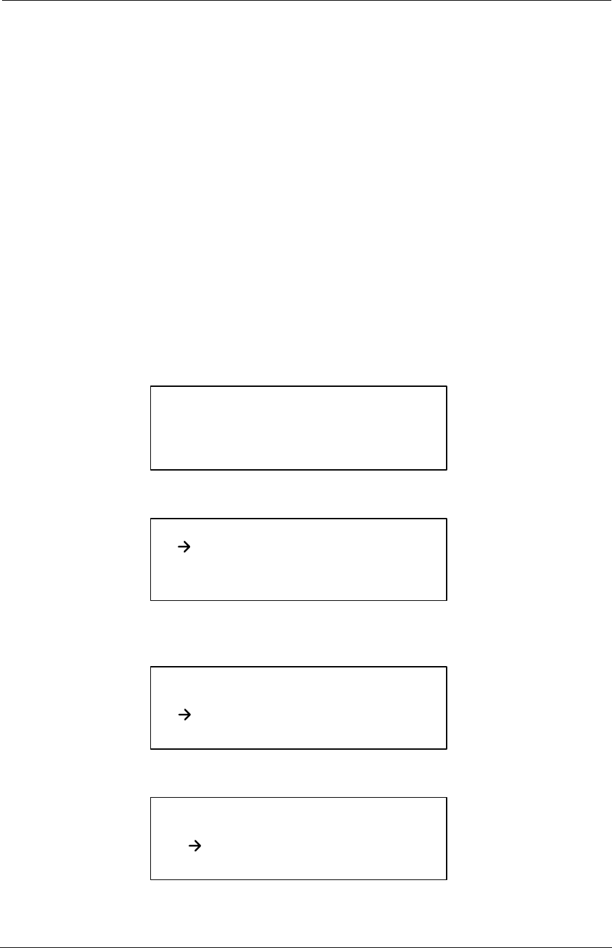
1. Press the On/Off button on the HHTR. The “flash” screen appears
momentarily displaying the software version number. Firmware
Vn.n is replaced with the firmware version number installed in your
HHTR.
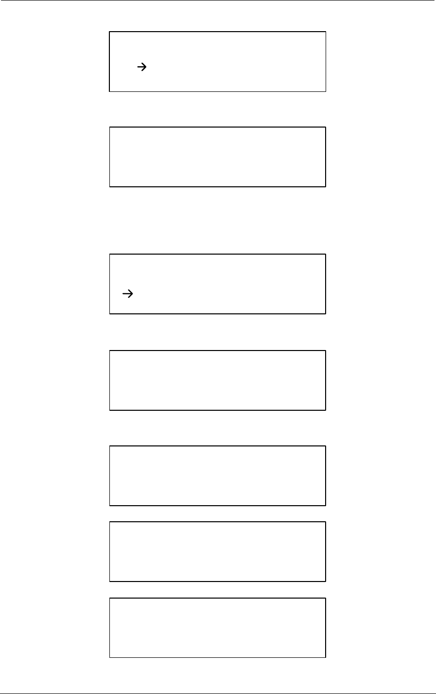
The Main Menu screen appears.
2. Press the down arrow once to position the arrow cursor in front of the
REMOTE option.
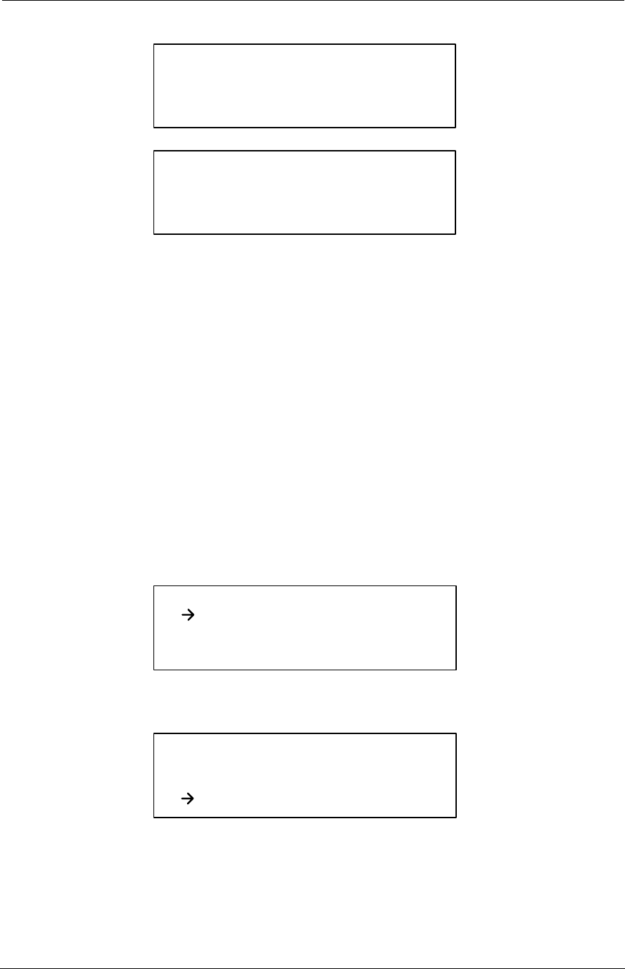
3. Press the Enter button.
4. Press the Enter button to accept the default selection.
DCSI: HHTR
Y72160-1
Www.twacs.com
Firmware Vn.n
Main Menu
Order Serial Com
REMOTE
EMTR TWACS
HHTR Config
Main Menu
Order Serial Com
REMOTE
EMTR TWACS
HHTR Config
Remote Menu
Select:
ORION
RMTR
14 TWACS® - ORION® for CENTRON® Meter User Guide
ORION and EMTR Communication Setup
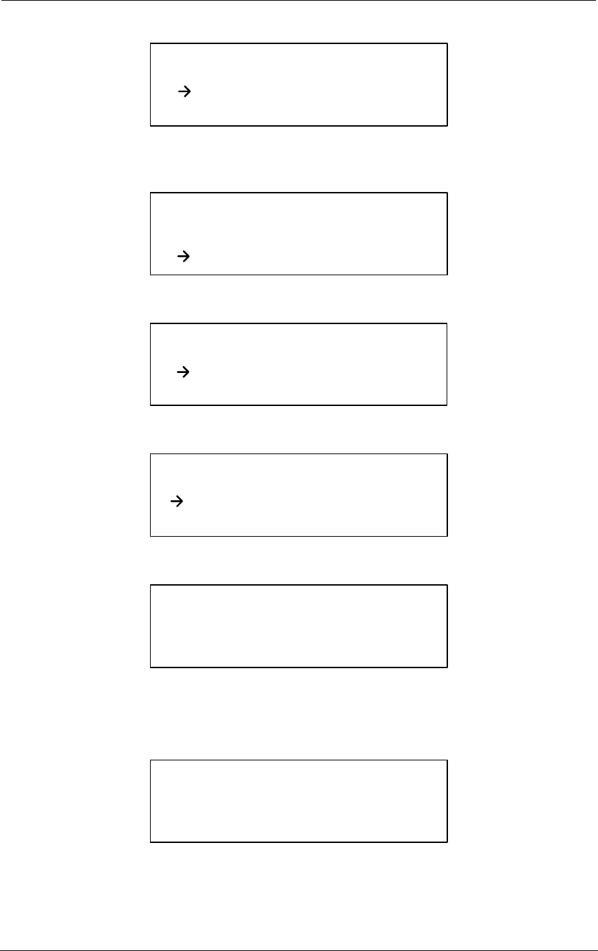
5. Press the Enter button to accept Install.
6. Enter the ORION serial number in the spaces provided, if it is not
automatically entered for you.
7. Press the Enter button.
8. Press the Enter button.
9. Press the Enter button.
Orion Menu
Select:
Install
Com Stat
Orion Install Menu
Enter the Serial #,
Enter To Accept
Orn S/N:_______
Orion Install Menu
Select:
Propane
Water
Electric
Nat Gas
Orion Install Menu
Enter the Serial #,
Enter To Accept
EMTR S/N:_______
Orion Install Menu
Checking EMTR Tables
Please Wait...
Orion Install Menu
Writing EMTR Tables
Please Wait...
Orion Install Menu
Waiting for EMTR to Acquire
Orion Data
Please Wait...
TWACS® - ORION® for CENTRON® Meter User Guide 15
Installation and Operation
10. Press the Esc button to return to the ORION Menu or press the down
arrow to view the current configuration status as described in
Configuration/Installation Status on page 22.
If you receive an error message, press the Esc button, then repeat steps
2-10.
N
OTE
Your previously selected options will appear on the screens when you
repeat steps 2-10. Make new selections, or press the Enter button to
accept each correct entry.
Delete the ORION from the Remt List
If your ORION and EMTR are not communicating, or if you need to replace a
malfunctioning ORION module, this procedure provides the instructions to
delete the ORION from the Remt List stored in the EMTR.
Complete the following steps to delete the ORION from the EMTR.
1. Press the On/Off button on the HHTR.
2. Press the down arrow button twice to position the cursor in front of
the EMTR option.
3. Press the Enter button.
Orion Install Menu
Checking EMTR Tables
Please Wait...
Orion Install Menu
Success!
EMTR: X
Orion: XXXX
Main Menu
Order Serial Com
REMOTE
EMTR TWACS
HHTR Config
Main Menu
Order Serial Com
REMOTE
EMTR TWACS
HHTR Config

16 TWACS® - ORION® for CENTRON® Meter User Guide
ORION and EMTR Communication Setup
4. Use the arrow buttons to select Delete.
5. Press the Enter button. The Remote Menu appears.
6. Press the Enter button.
7. Enter the serial number of the EMTR in the EMTR S/N field, if it is
not automatically entered for you.
8. Press the Enter button.
9. Enter the Orion serial number in the Orn. S/N field, if it is not
automatically entered for you.
10. Press Enter to accept.
The following two screens display briefly.
EMTR Menu
Select
Status
Replace Delete
Remt List
Remote Menu
Select:
ORION
RMTR
EMTR: Delete Orion
Enter the Serial #,
Enter To Accept
EMTR S/N:_______
EMTR: Delete Orion
Enter the Serial #,
Enter To Accept
Orn. S/N:_______
EMTR: Delete Orion
Receiving Orn. List,
Please Wait...
EMTR: Delete Orion
Found Orion, Working,
Please Wait...

TWACS® - ORION® for CENTRON® Meter User Guide 17
Installation and Operation
The Success! screen displays, indicating that the ORION has been
successfully removed from the Remt List table stored in the EMTR.
11. Press the Esc button twice to return to the Main Menu screen.
Replace the EMTR
This procedure downloads the Remt List from the existing EMTR to the
HHTR so the Remt List can be uploaded to the replacement EMTR.
Two important conditions apply to this procedure:
1. The existing EMTR must be able to communicate with the ORION for
the Remt List to be downloaded to the HHTR, to simplify reinstalling
applicable ORIONs.
N
OTE
If communication is not possible, this procedure can not be performed.
Replace the existing meter according to your utility procedures, and
perform Install the ORION (Linking the ORION and EMTR) on page 13 to
install the individual ORIONs.
2. This procedure requires the physical removal of the existing installed
meter and installation of a replacement meter/EMTR combination.
Perform the following procedure to replace an EMTR.
If you pressed the HHTR On/Off button at the end of any previous procedure,
begin with step 1.
-OR-
If you pressed the Esc button, begin with step 2.
1. Press the On/Off button on the HHTR.
Press the down arrow button to position the cursor in front of the
REMOTE option.
EMTR: Delete Orion
Success!
Main Menu
Order Serial Com
REMOTE
EMTR TWACS
HHTR Config
18 TWACS® - ORION® for CENTRON® Meter User Guide
ORION and EMTR Communication Setup
2. Press the down arrow button to position the cursor in front of the
EMTR option.
3. Press the Enter button. The EMTR menu appears.
4. Press the Enter button. The following screen appears.
5. Press the Enter button. The following screen appears.
6. Enter an Order number if different from that displayed and press
Enter to Accept.
The following screen appears.
7. Press the Enter button. The following two screens appear.
Main Menu
Order Serial Com
REMOTE
EMTR TWACS
HHTR Config
Main Menu
Order Serial Com
REMOTE
EMTR TWACS
HHTR Config
EMTR Menu
Select
Status
Replace Delete
Remt. List
EMTR: Replacement
Select:
Read Old EMTR
Write New EMTR
EMTR: Replacement
Verify Order #
XXXXX
ESC: No, Enter: Yes
EMTR: Replacement
Enter the Serial #,
Enter To Accept
Old S/N: XXXXXXX
TWACS® - ORION® for CENTRON® Meter User Guide 19
Installation and Operation
N
OTE
At this point in the procedure, the technician must replace the “old” utility
meter with a replacement integrated meter/EMTR combination.
8. Press the Esc button once and the following screen appears.
9. Press the Enter button. The Order Number screen appears.
10. Enter the order number and press the Enter button. The following
screen appears.
11. Press the Enter button. The following two screens appear.
EMTR: Replacement
Receiving RMTR List,
Please Wait...
EMTR: Replacement
Success!
EMTR: Replacement
Select:
Read Old EMTR
Write New EMTR
EMTR: Replacement
Verify Order #
XXXXX
ESC: No, Enter: Yes
EMTR: Replacement
Enter the Serial #,
Enter To Accept
New S/N: XXXXXXX
EMTR: Replacement
Verifying New EMTR,
Please Wait...

20 TWACS® - ORION® for CENTRON® Meter User Guide
ORION and EMTR Communication Setup
12. Press the Esc button three times to return to the Main Menu screen.
-OR-
Press the On/Off button.
EMTR: Replacement
Success!

TWACS® - ORION® for CENTRON® Meter User Guide 21
CHAPTER
2
T
ESTING
, T
ROUBLESHOOTING
,
AND
M
AINTENANCE
This chapter explains how to test and manage typical TWACS-ORION
system problems. It is useful for installers and meter shop personnel.
Chapter at a Glance
Troubleshooting and Error Messages . . . . . . . . . . . . . 22
Configuration/Installation Status. . . . . . . . . . . . . . 22
HHTR Displayed Error Codes . . . . . . . . . . . . . . . . 26
Remote Test Set (RTS) . . . . . . . . . . . . . . . . . 27
Meter Shop Test System . . . . . . . . . . . . . . . . . . . 30
Maintenance . . . . . . . . . . . . . . . . . . . . . . . . 30
Warranty. . . . . . . . . . . . . . . . . . . . . . . . . . 30
Return Procedures . . . . . . . . . . . . . . . . . . . . . 31

22 TWACS® - ORION® for CENTRON® Meter User Guide
Troubleshooting and Error Messages
Troubleshooting and Error Messages
When necessary, the HHTR can run a self-diagnostics test. If there is a
problem, it will respond with an appropriate error code.
For RF communication, and HHTR or user error codes, refer to HHTR
Displayed Error Codes on page 26.
For more information about Trouble Server Applications, refer to the
Trouble Server Applications chapter in the TNS documentation
Troubleshooting Scenarios
There are two basic types of troubleshooting scenarios:
• Configuration/Installation Status
• Field Troubleshooting
Configuration/Installation Status
You can view additional information about configuration and link status by
selecting Com Stat from the ORION Menu screen. Although this
information is read from the EMTR, check the RF Link Data: Acq Log
(refer to step 16. of this procedure) to verify recent successful
ORION/EMTR communication.
Complete the following steps to view configuration and link status data.
1. Press the On/Off button on the HHTR. The “flash” screen appears
momentarily displaying the software version number. Firmware
Vn.n is replaced with the firmware version number installed in your
HHTR.
The Main Menu screen appears.
DCSI: HHTR
Y72160-1
Www.twacs.com
Firmware Vn.n
Main Menu
Order Serial Com
REMOTE
EMTR TWACS
HHTR Config
TWACS® - ORION® for CENTRON® Meter User Guide 23
Chapter 2 • Testing, Troubleshooting, and Maintenance
2. Press the down arrow once to position the arrow cursor in front of the
REMOTE option.
3. Press the Enter button.
4. Press the Enter button to accept the ORION default selection.
5. Press the down arrow once to position the arrow cursor in front of the
Com Stat option.
6. Press the Enter button.
7. Enter the ORION serial number in the spaces provided.
8. Press the Enter button.
9. Enter the EMTR serial number in the spaces provided.
10. Press the Enter button.
Main Menu
Order Serial Com
REMOTE
EMTR TWACS
HHTR Config
Remote Menu
Select:
ORION
RMTR
Orion Menu
Select:
Install
Com Stat
Orion Menu
Select:
Install
Com Stat
Orion Com Status
Enter the Serial #,
Enter To Accept
Orn S/N:_______
Orion Com Status
Enter the Serial #,
Enter To Accept
EMTR S/N:_______

24 TWACS® - ORION® for CENTRON® Meter User Guide
Troubleshooting Scenarios
The following two screens appear.
11. Press the down arrow or the Enter button and the following status
screen appears.
•Reading: displays the number on the ORION. A correct number
(0000000000-9999999999) here verifies proper equipment operation.
12. Press the down arrow or the Enter button.
• Ignore Meter Com.
• Ignore the Hist MTR Com entry for installation purposes.
•LeakDet options are Y or N. Site visit is required to locate leak if Y.
• Ignore the Tamper entry for installation purposes.
13. Press the down arrow or the Enter button.
•RSSI (Received Signal Strength Indicator) indicates the signal
strength. The range is 0-255 with 255 being the best.
14. Press the down arrow or the Enter button
Orion Com Status
Collecting data from
EMTR.
Please Wait...
Orion Com Status
Success!
EMTR:_________
Orion:_________
Orion Com Status
Battery: N/A
Reading: 1234567890
N/V Memory: N/A
Orion Com Status
Hist MTR Com: N/A
Meter Com: N/A
LeakDet: N Tamper: N
Orion Com Status
RF Link Data:
PA: N/A
Link: N/A RSSI: 123

TWACS® - ORION® for CENTRON® Meter User Guide 25
Chapter 2 • Testing, Troubleshooting, and Maintenance
Ignore this screen for installation purposes.
15. Press the down arrow or the Enter button
Ignore this screen for installation purposes.
16. Press the down arrow or the Enter button
The Acq Log displays 24 bits (in three groups of eight) representing
the hourly check-in for the last 24 hours. A one (1) indicates that the
hourly check-in was successful and a zero (0) indicates that it was not.
The least significant bit (bottom right) indicates the past hour check-in
status. Each hour the bits are shifted one position to the left. In the
example below, the ORION successfully checked in the past hour, but
did not for each of the previous three hours.
Press the On/Off button to turn the HHTR Off.
Field Troubleshooting
The most likely field troubleshooting scenario is a failure of the power up
LED to flash. If the LED on theTWACS-ORION system is not flashing,
ensure that the TWACS-enabled meter is receiving the appropriate power
according to its specific form and voltage (refer to Installation on page 21).
You may use a Remote Test Set (RTS) for further testing or return the meter
to the Meter Shop for further diagnostics.
Last Ch: N/A
RF Link Data:
Acq Failures: 0
Orion Com Status
Orion Com Status
Lnk Abandonment: N/A
RF Link Data:
Error Code: N/A
Orion Com Status
RF Link Data: 24 Hr
Acq Log:
00000000 00000000
00000000
Acq Log: 11111111
11111101 11110001

26 TWACS® - ORION® for CENTRON® Meter User Guide
Troubleshooting Scenarios
HHTR Displayed Error Codes
The following table lists the error code number and error message text that
the HHTR displays when the specific error is encountered while using the
HHTR to communicate with the TWACS-ORION system.
Table 0.1
Error Code Description and Solution
Error Description Solution
The following error codes are RF communication errors.
01 RF Error General error. Retry the command.
02 Service Not Supported Service is not supported. Retry the command.
03 Not used
04 Operation Not Possible RF error. Retry the command.
05 Inappropriate Action
Requested RF error. Retry the command.
06 RF Device Busy RF error. Retry the command.
07 Data From Device Not
Ready RF error. (Usually memory) Retry the command.
31 RF Device Sent NAK RF error Retry the command.
32 Can not acquire an RF Link RF error Retry the command.
33 Operation Timed Out Operation time expired without
success. Retry the command.
The following error codes are internal HHTR or user errors.
101 RF PIC sends a NAK The RFPIC isn't ready or doesn't
understand the command. The RF
PIC internal to the HHTR has
failed.
Retry the command.
102 RF PIC is busy RFPIC is performing another
operation and is currently busy.
The RF PIC internal to the HHTR
was in the middle of another
command.
Retry the command.
103 No response from RF PIC
on HHTR The RFPIC isn't responding to the
UI. No Response from the RF
PIC. The RF PIC didn't respond
to the UI processor.
Retry the command.
104 RF PIC send invalid
response The RFPIC sent an invalid
response to the UI. The HHTR UI
processor didn't recognize the
response from the RF PIC.
Retry the command.
105 Operation canceled Indicates the Esc button was
pressed during an operation. The user aborted the last
command.
106 RMTR-EMTR session
failed The HHTR timed out waiting for
the RMTR to respond back to the
HHTR.The HHTR was unable to
link to the requested EMTR.
Verify the serial number
and retry the command.

TWACS® - ORION® for CENTRON® Meter User Guide 27
Chapter 2 • Testing, Troubleshooting, and Maintenance
Remote Test Set (RTS)
Follow the procedures below to verify that the RTS can communicate to the
TWACS-ORION system.
W
ARNING
Installers must follow all utility electrical safety requirements before
connecting the RTS.
Consult applicable utility procedures when troubleshooting this
equipment.
1. Connect the RTS according to procedures outlined in the RTS User
Guide, Y10228TM.
2. Connect the RTS to an appropriate power source, 120VAC or
240VAC.
107 No Space Available in
EMTR. The Table is Full. The EMTR is at capacity. It can
not accept additional Remotess. A Remote must be
removed before adding
another.
112 EMTR already has
Remotes assigned Can not program a new EMTR
with the data from an old EMTR
because the new EMTR already
has Remotes assigned.
Remove all Remotes from
the new EMTR first.
113 The New EMTR can not
accept xx Number of
Remotes.
Can not program a new EMTR
with the data from an old EMTR
because the new EMTR can not
store as many Remote as the old
EMTR.
114 An order needs to be
created first. Use the order
menu
When replacing an EMTR, the
HHTR needs to store the Remt
list. An “order number” needs to
be assigned so that the HHTR has
a location to store the list.
Select “order” from the
main menu, select “new”
and enter a number.
208 ORION S/N Already
exists in the EMTR Table. Can not install the selected
ORION because it is already
installed.
209 The Selected ORION is
NOT in the EMTR Table. Can not remove the ORION nor
perform a Com Status because
that ORION is not installed to the
selected EMTR.
Check serial number and
try again.
211 Service is Full, Can not
add ORION to the EMTR
List.
This service in the EMTR is at
capacity. It can not accept
additional Orions.
An ORION must be
removed from this service
before adding another.
215 The Selected Remt. is
NOT an Orion.
Table 0.1
Error Code Description and Solution
Error Description Solution
28 TWACS® - ORION® for CENTRON® Meter User Guide
Troubleshooting Scenarios
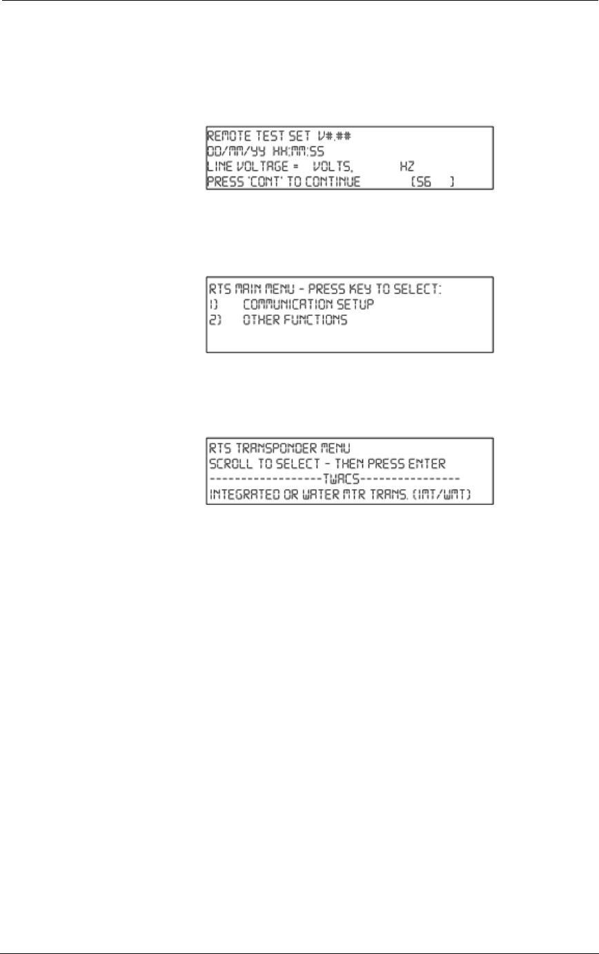
3. Turn the power switch to the ON position. The initial screen
appears, displaying the version of firmware, date, time, line voltage,
and the frequency of the line voltage:
Figure 2.1
RTS initial screen
4. Press the Cont button on the RTS to display the RTS Main Menu.
The Main Menu screen appears:
Figure 2.2
RTS main menu
5. Press 1 for communications setup. This action brings up the RTS
Transponder Menu.
Figure 2.3
RTS transponder menu
6. Press on the Scroll Down button to select the type of remote
communication. Scroll down to find the screen that reads
“Electronic Meter Transponder (EMT)” and press Enter.
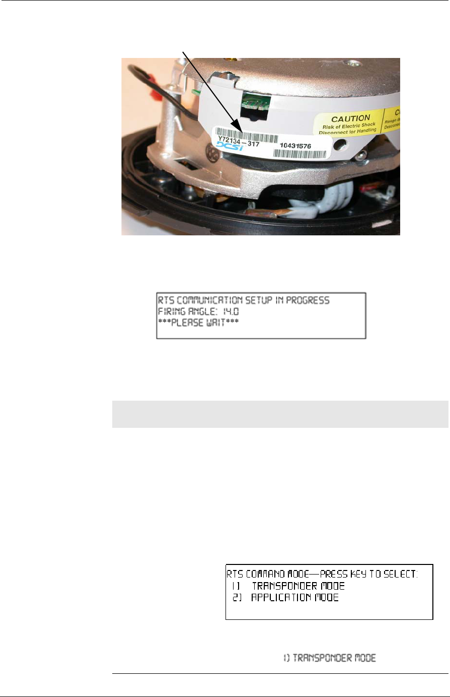
7. At the ENTER SERIAL NUMBER prompt on the next screen, input
the TWACS serial number of the unit (see picture below to locate
serial number) to be tested (press DEL to correct errors) and press
Enter.
TWACS® - ORION® for CENTRON® Meter User Guide 29
Chapter 2 • Testing, Troubleshooting, and Maintenance
Figure 2.4
TWACS serial number location
8. The RTS will attempt to communicate with the TWACS-ORION
system. A series of setup screens will appear.
Figure 2.5
RTS setup screens
The RTS begins with a firing angle of 14 degrees and gradually
increases until it fails or until communication setup is complete.
Table 2.2
RTS communication success or failure
If the
communication… Then…
fails the firing angle sequence will end at 26 degrees and
start over at 14 degrees. Check the electrical
connections and verify that the correct TWACS
serial number was entered. If there is no problem
with the setup, replace the TWACS-enabled meter
and retry the communication setup. Return the
failed meter to the meter shop. Refer to Return
Procedures on page 31.
succeeds the following screen appears:
Select
TWACS S
er
i
a
l N
um
b
er

30 TWACS® - ORION® for CENTRON® Meter User Guide
Meter Shop Test System
9. At this point, the RTS has verified that the TWACS-ORION system
is capable of communicating. To further verify that the
communication is reliable, select any command to conduct another
test. (For more details on RTS commands, refer to the Common
Generic Commands section in RTS User Guide). Or, if testing is
complete, turn off the power switch.
10. Wait 15 minutes to allow the thermal capacity to recover. Then
verify that the TWACS-ORION system can communicate with the
software system
11. If the TWACS-ORION system is not communicating, return the
meter to the Meter Shop for additional testing.
Meter Shop Test System
Use the Meter Shop Test System (MSTS) to test TWACS signaling, read
select transponder registers, zero select transponder registers, and perform
various other transponder functions on the TWACS-ORION system.
MSTS configurations exist for both the meter shop and field use. The
hardware components vary for each configuration, but all configurations
utilize DCSI's Meter Shop Test Tool software. (For information about the
MSTS, contact your Program Manager or DCSI Customer Care at
care@twacs.com or 1-800-892-9008.) Complete details on testing the
TWACS-ORION system are available through the Meter Shop Test
System Help, accessed by clicking the Help button on the Meter Shop Test
Tool main menu.
Two modes of communication with the TWACS-ORION system are
available through the Meter Shop Test System: TWACS signaling and
serial communication. (Refer to Meter Shop Test System Help for the
benefits and use for each.) To use the serial communication option, you
must have the correct SIA Cable Assembly, which is available through
DCSI.
If you are unable to resolve a problem with the TWACS-ORION system,
return the meter to your integrator or DCSI. See Return Procedures on
page 31.
Maintenance
The TWACS-ORION system requires no maintenance.
Warranty
Refer to contract terms for warranty information.

TWACS® - ORION® for CENTRON® Meter User Guide 31
Chapter 2 • Testing, Troubleshooting, and Maintenance
Return Procedures
Electromechanical meters/modules which have been integrated or retrofitted
by a third party, must be returned to the third party. Please do not return third
party integrated meters/modules to DCSI. Contact the third party to obtain
their “Return Authorization Number” and shipping instructions and return the
meter/module directly to the integrator/retrofitter.
If you are a DCSI certified integrator, and the product is under warranty and
cannot be repaired in the meter shop, remove the module from the meter and
complete the following procedures.
Before returning the product to DCSI, refer to contract terms for warranty
information.
1. Send your return request via email to rma@twacs.com with the
following information:
•Company name (Distributor name and location (City, State) if applicable)
•Ship to name and address
•Contact name, phone number, and email address
•DCSI part number of each item
•Total quantity (by DCSI part number) for each returned item
•Serial number of each item
•Specific reason for return of each item
•Manufacturer number (number starting with A/M/V/C/W) of each
RCE item
•Description of each returned item
•Substation Communications Equipment (SCE) name
•You will receive an email from DCSI within 24 hours, excluding
weekends and holidays.
•Upon receipt of all required information you will receive a Return
Material Authorization (RMA) with the shipping instructions.
I
MPORTANT
Items should be properly packaged to avoid shipping/handling damage
during transit.
32 TWACS® - ORION® for CENTRON® Meter User Guide
Return Procedures
Items must be packaged in individual anti-static or static dissipative
bags and packed in sturdy, appropriately sized commercial boxes
with packing material (styrofoam peanuts, bubblewrap, paper, etc.)
arranged to prevent movement; in single layers; with the appropriate
packaging between layers. Original packaging with dividers should
be retained, reused, and re-identified if possible.
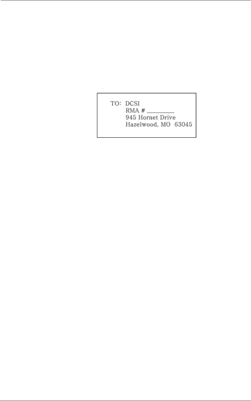
2. Mark the outside of the shipping container with the RMA number
on the address label as shown in the following example:
Figure 2.6
Return address Label
3. Upon shipment, email rma@twacs.com with the shipping
information (Carrier Name, Waybill/Pro/Tracking Number and
Date item left your facility) so DCSI can track the shipment.
4. If an item is out of warranty, please contact rma@twacs.com for a
diagnostic estimate prior to return.
IMPORTANT
Items not packaged in accordance with DCSI packing requirements will
not be accepted and will be returned freight collect. Please refer to
the Returned Merchandise Packing Requirement Service Advisory
(Y10377TM) for DCSI approved methods and materials. Contact DCSI
Customer Care at care@twacs.com to receive a copy of this service
advisory.
If you have any additional questions regarding returns, contact
rma@twacs.com.

TWACS® - ORION® for CENTRON® Meter User Guide 33
CHAPTER
3
S
PECIFICATIONS
This chapter contains electrical, environmental, and physical specifications
for the EMTR and HHTR.
Chapter at a Glance
Electrical Specifications. . . . . . . . . . . . . . . . . . . 34
Electrical Ratings. . . . . . . . . . . . . . . . . . . . . 34
Compliance Specifications. . . . . . . . . . . . . . . . . 34
Environmental Specifications . . . . . . . . . . . . . . . . 35
Physical Specifications . . . . . . . . . . . . . . . . . . . 35

34 TWACS® - ORION® for CENTRON® Meter User Guide
Electrical Specifications
Electrical Specifications
The electrical specifications include:
• Electrical ratings
• Compliance Specifications
Electrical Ratings
The following table provides the electrical ratings.
Compliance Specifications
The following table provides the compliance specifications.
N
OTE
ANSI C12.1-2001 is the referring standard for tests listed in tables 5.2,
5.3, and 5.4.
Table 3.1
Electrical ratings
Parameter Rating
Voltage 6V<=V<=12V
Quiescent power 25mA approximate
Maximum input surge 100mA maximum
Internal fusing None
Grounding None
Electronics connection The EMTR is connected to the
EMT-3C-MP transponder during
meter/transponder integration.
Electronics isolation Refer to the Electronic Metering Transponder
for CENTRON Meter User Guide Y10317TM
Rev. A.
Table 3.2
Compliance specifications
Test Title Applicable Specification
EMI/RFI Emission
conducted/radiated ANSI C12.1-2001 Test No. 27- “Radio
Frequency Conducted and Radiated Emissions”
per CFR 47 Part 15, Class A and B. (See also
ANSI C63.4)
EMI/RFI Susceptibility ANSI C12.1-2001 Test No. 26- “Effect of Radio
Frequency Interference”
AC line surge ANSI C12.1-2001/IEEE C62.41-1991 Test No.
17- “Effect of High Voltage Line Surges”
Electrical fast transient ANSI C12.1-2001 Test No. 25- “Electrical Fast
Transient/Burst” (Testing at 100 and 400 KHz is
required) IEC 801-4: 1988
Surge withstand
capability FT and OSC ANSI/IEEE C.37.90.1 - 2002

TWACS® - ORION® for CENTRON® Meter User Guide 35
Chapter 3 • Specifications
N
OTE
Per Measurement Canada, Specifications/Standards LMG-EG-07 &
PS-E-09-E are used to verify compliance with Canadian criteria.
Environmental Specifications
The following table provides the environmental specifications.
Physical Specifications
The following table provides the physical specifications.
High voltage isolation on
meter chassis ANSI C12.1-2001 Test No. 15- “Insulation”
Voltage interruption test ANSI C12.1-2001 Test No. 16- “Voltage
Interruption”
Effect of electrostatic
discharge ANSI C12.1-2001 Test No. 28- “Effect of
Electric Discharge (ESD)”
Effect of Variation of
Frequency ANSI C12.1-2001. Test #6
Effect of Variation of
Voltage on the Metering
Device
ANSI C12.1-2001. Test #5.
Table 3.2
Compliance specifications
Test Title Applicable Specification
Table 3.3
Environmental specifications
Thermal
Effect of operating temperature Per ANSI C12.1-2001 Test No. 30
Humidity
Effect of relative humidity, both
operational and storage Per ANSI C12.1-2001 Test No. 31
Table 3.4
Physical specifications
Parameter Specification
Size, weight, form factor
Integrated dimensions Meter-specific
Installation instructions Provided with shipping package. One per
TWACS-enabled meter carton.
Compliance Testing Specifications
Mechanical tests
• Mechanical Shock
• Mechanical Vibration
• Transportation Drop Test
• Transportation Vibration
Per relevant sections of ANSI C12.1 - 2001
described below:
• Test #32, per IEC 60068 part 2-27
• Test #34, per IEC 60068 part 2-6
• Test #33, per ISTA Test Procedure 1A
• Test #35, per ISTA Test Procedure 1A

36 TWACS® - ORION® for CENTRON® Meter User Guide
Physical Specifications
Physical Tamper Protection
Meter seal Supported
Table 3.5
Labeling requirements
Labeling Requirements and Serial Number
HHTR
Labeling per ANSI C12.10-1987 for:
• DCSI/customer name
• DCSI/customer logo
• TWACS serial number
•Barcode
Table 3.4
Physical specifications
Parameter Specification
Photo to be supplied

TWACS® - ORION® for CENTRON® Meter User Guide 37
ADLC Asynchronous Data Link Control
AMR Automatic Meter Reading
AP Alternate Pathmaps
ASCII American Standard Code for Information Interchange
BPA Backplane Assembly
CCA Card Cage Assembly
CCE Central Control Equipment
CIS Customer Information System
CLI Command Line Interface
CMT Commercial Meter Transponder
CPSA CRU Power Supply Assembly
CRA Correlation Receiver Assembly
CRMA Correlation Receiver Multiplexer Assembly
CRPA Correlation Receiver Processor Assembly
CRU Control and Receiving Unit
CT Current Transformer
DCPA Direct Current Power Assembly
DCSI Distribution Control Systems, Inc.
DP Diagnostic Pending
DPA Distribution Panel Assembly
DS Diagnostic Set
DSI Disconnect Switch Interbase
EMA Electronic Metering Assembly
EMTR Electronic Meter Transceiver
EOM End of Message
FEP Front-End Processor
FCC Federal Communication Commission
FSK Frequency Shift Keying
GUI Graphical User Interface
HHTR Hand Held Transceiver
IC Incomplete IMT/CMT Data
ILS Integrated Load Survey
Acronyms

38 TWACS® - ORION® for CENTRON® Meter User Guide
Acronyms
IMA Inbound Multiplexer Assembly
IMT Integrated Metering Transponder
IP In Progress
IPU Inbound Pickup Unit
ISM Industrial, Science, and Medical
KWH Kilowatt Hours
LCT Load Control Transponder
LS Load Survey
MIT Meter Interface Transponder
MS Master Station
MSFE Master Station Field Equipment
MTU Modulation Transformer Unit
NA Invalid Data
NS Register Not Supported
ODBC Open Database Connectivity
OFIA Outbound Fiber Optics Interface Assembly
OK Successful Read
OMU Outbound Modulation Unit
OPA Outbound Processor Assembly
PD Partial Data
PE Pending
PR Pending Retry
QC Quality Code
RC Reasonability Check Failed
RCE Remote Communications Equipment
RF Radio Frequency
RI Reset In Progress
RL Register Length Invalid
RM Read Meter
RMTR Remote MeterTransceiver
RO Retry Override
RPA Receiver Processor Assembly
RSSI Received Signal Strength Indicator
SCADA Supervisory Control and Data Acquisition
SCE Substation Communications Equipment

TWACS® - ORION® for CENTRON® Meter User Guide 39
Acronyms
SCPA Substation Communications Processor Assembly
SDC Service Disconnect/Connect
SP Substation Status
STS Substation Test Set
TC Total Consumption
TD Total Demand
TNS TWACS Net Server
TOU Time of Use
TP Tamper Pending
TS Tamper Set
TWACS Two-Way Automatic Communication System
UHF Ultra High Frequency
ZC Zero Crossing

40 TWACS® - ORION® for CENTRON® Meter User Guide
Acronyms

TWACS® - ORION® for CENTRON® Meter User Guide 41
American National Standards Institute (ANSI)
An independent, U.S.-based technical standards organization.
AMR
See Automatic Meter Reading.
ANSI
See American National Standards Institute.
Automatic Meter Reading (AMR)
Electronic accumulation and transport of meter data.
billing demand information
Consists of the demand reset count, which increments, and the demand previous billing.
billing read
Defines the registers used during one-time scheduled reads and on-request reads.
DSHTBill read (Daily Shift Billing)
Defines the registers used during recurring scheduled reads; normally used to create
billing files.
blink count
See power-down count.
bus identification
Identifies the substation bus to which DCSI’s equipment is connect.
CCE
See Central Control Equipment.
Central Control Equipment (CCE)
The top level of the TWACS system hierarchy, also referred to as the Master Station. The
CCE typically resides at the utility home office, providing system control and data
storage for the TWACS system.
CIS
See Customer Information System.
Glossary

42 TWACS® - ORION® for CENTRON® Meter User Guide
Glossary
CMT
See Commercial Metering Transponder.
Customer Information System (CIS)
A computer database that utilities use to keep track of their customer information
(name, address, phone, meter serial number). Often includes bill printing
functionality.
Commercial Metering Transponder (CMT)
An electronic assembly integrated into a commercial application electric meter to add
TWACS communications capability to the meter.
Daylight Saving Time (DST)
Daylight Saving Time is the practice of turning the clock ahead in the Spring and back
again in the Fall.
delay
The number of minutes after the interval has occurred before the SCE attempts to send
a time sync command to the RCE.
demand
The rate at which power is delivered over a specified period of time; the rate of
consumption. Demand is expressed in kilowatts.
demand interval
The specified interval of time on which a demand measurement is based. Intervals are
commonly specified as 15, 30, and 60 minutes.
demand meter
A metering device that indicates or records demand, maximum demand, or both.
detection point
Identifies the specific conductor on which the inbound signal is detected. This point is
identified as either A phase, B phase, C phase, or neutral.
dial encoder
A device that encodes or converts the position of metering dials (normally used in
water meters) into an electrical signal for subsequent processing and transmission.
DST
See Daylight Saving Time

TWACS® - ORION® for CENTRON® Meter User Guide 43
Electronic Metering Assembly (EMA)
An electronic assembly integrated into an electric meter to add TWACS communications
capability to the meter.
Electronic Meter Transceiver (EMTR)
An electronic communication device that transmits and receives using RF transmission.
EMA
See Electronic Metering Assembly.
EMTR
See Electronic Meter Transceiver.
Federal Communication Commission (FCC)
The Federal Communications Commission (FCC) is an independent United States
government agency, directly responsible to Congress, and is charged with regulating
interstate and international communications by radio, television, wire, satellite and cable.
Among its duties, the FCC is responsible for rating personal computers and other
electronic equipment as either Class A or Class B. The ratings indicate how much
radiation a particular device emits.
feeder identification
Identifies which feeders are connected to which bus(es).
firing angle
The place on the sine wave where the RTS places the TWACS signal.
frequency shift keying
A data transmission control method that modulates, i.e. “shifts” between two radio
frequencies.
hand held transceiver (HHTR)
A control device used to set up, link, and establish communication between the EMTR
and RMTR components of the TWACS RF system.
industrial, science, and medical (ISM)
An unlicensed radio frequency band.
interval
A relatively short time period over which energy use data is recorded by the transponder.
The interval may be set for 15, 30, or 60 minutes, depending on the transponder type.
Interval data is recorded for each consecutive interval.

44 TWACS® - ORION® for CENTRON® Meter User Guide
Glossary
interval data
A breakdown of consumption over specific intervals of time.
ISM
See Industrial, Science, and Medical.
load profile
Recording, storing, and analyzing consumption data over a period of time for a
particular installation.
master station
See Central Control Equipment (CCE).
maximum demand
The highest demand measured over a selected period of time, such as one month.
Meter Integration and Meter Test (MIMT)
A department within DCSI that reviews utility meter programming files and
determines register programming requirements.
MIMT
See Meter Integration and Meter Test.
nonvolatile memory
A physical data storage area that maintains its content when the power is turned off.
on-demand reads
An unscheduled command to read a register.
ORION Transmitter
A one-way (simplex) radio frequency transmitter, manufactured by Badger Meter Inc.,
that allows retrieval of metering data from pit-set water, water, and gas meters. It
periodically broadcasts a data packet.
PCB
See Printed Circuit Board.
peak demand
See maximim demand.

TWACS® - ORION® for CENTRON® Meter User Guide 45
phase
The current supply conductors, other than the neutral conductor of a polyphase circuit,
that usually carry the designation A phase, B phase, C phase.
power-down count
A voltage interruption greater than 0.1 seconds that the module will count as a power
outage and will increase the power-down count register by one. Sometimes referred to as
blink count.
previous billing demand
The maximum kW, or demand, as recorded at the time of the last reset. This value is
normally used for billing purposes.
previous interval demand
The demand value stored in the meter that reflects the demand prior to the last reset.
Printed Circuit Board (PCB)
A thin plate on which electronic components are placed.
pulser
An electronic or magnetic device that generates electric pulses in a quantity that is
proportional to the physical variable under measurement and which the pulses represent.
rate class
A rate class is a set of registers read for a particular class of customer with a particular
meter model. It defines registers used for Billing and DSHTBill reads.
RCE
See Remote Communication Equipment.
received signal strength indicator (RSSI)
A value indicating the strength of the received radio frequency signal.
registers
Data storage locations on the transponder microprocessor that contain a variety of
information that is retrievable by the master station. The type of data in registers includes
consumption and demand data

46 TWACS® - ORION® for CENTRON® Meter User Guide
Glossary
Remote Communication Equipment (RCE)
The base of the TWACS system hierarchy. RCEs consist of the DCSI family of
transponder products. RCEs are located at customer sites and interface TWACS
communication with various end devices such as meters, water heaters, and air
conditioning units to enable automatic meter reading (AMR), load management, or
other functions.
Remote Test Set (RTS)
A TWACS communications test device used at a remote site to communicate locally,
using TWACS, to a transponder over the power line.
Remote Meter Transceiver (RMTR)
An electronic communication device that transmits accumulated data using RF
transmission.
Remote Acquisition List
A list of Remote Meter Transceivers stored in the EMTR.
RSSI
See Received Signal Strength Indicator.
RTS
See Remote Test Set.
SCE
See Substation Communication Equipment.
Serial Time Unit (STU)
A 2.5 seconds interval of time and the unit of measure of DCSI’s Serial Time system.
The intervals of time begin at 12:00 midnight on a cyclic 24-hour basis. Example:
1:00 a.m. would in serial time:
signal mode
Identifies the path combination used during outbound communications. This
combination can be either line-to-ground or line-to-line.
STU
See Serial Time Unit

TWACS® - ORION® for CENTRON® Meter User Guide 47
Substation Communications Equipment (SCE)
The middle tier of the TWACS system hierarchy, consisting of all TWACS substation
equipment (CRU, OMU, IPU, and MTU). The SCE transmits and receives data between
CCE and RCE.
time-of-use (TOU)
A multiple tiered billing technique based on when the consumer uses the energy.
TNS
See TWACS Net Server.
TOU
See time-of-use
transponders
Two-way field devices that can receive and send messages to and from the substation.
TWACS
See Two-Way Automatic Communication System.
TWACS Net Server (TNS)
Chief component of the entire Two-Way Automatic Communication System. Manages
all collected metering and interval data as well as the connection between the utility and
the consumer’s premises.
Two-Way Automatic Communication System (TWACS)
A patented technology that allows the utility to send and retrieve information to and from
meters and other devices using the utility’s power lines as a communication network.
Ultra High Frequency (UHF)
A frequency range in the radio frequency spectrum between 300 MHz and 3.0 GHz.
window
The amount of time in minutes available after the delay has occurred for the SCE to send
a date/time command.

48 TWACS® - ORION® for CENTRON® Meter User Guide
Glossary

TWACS® - ORION® for CENTRON® Meter User Guide 49
A
acquisition list, Remt 8, 15, 17
acronyms 37
ANSI 41
B
Badger Meter, Inc 2
C
care@twacs.com 4
caution icon 3
communication 9
compliance specifications 34
current configuration 15
customer care 4
D
Delete 15
E
electric meter transceiver 2, 4, 17
electrical ratings 34
electrical specifications 34
EMTR
See electric meter transceiver
environmental specifications 35
error codes 22
F
FCCSee federal communications commission
federal communications commission 3
firing angle 29
frequency hopping 3
frequency shift keying 3
FSKSee frequency shift keying
G
glossary 41
H
hand held transceiver 2, 6
keypad functions 6
menus 7
HHTR
See hand held transceiver
I
industrial, science, and medical band 3
ISM band
See industrial, science, and medical band
L
labeling requirements 36
line of sight 2, 9
linking, ORION and EMTR 13
M
maintenance 30
menus, HHTR
EMTR 8
delete 8
Remt list 8
replace 8
status 8
HHTR Config 8
diags 8
power 8
setup 8
status 8
Remote 7
RMTR 8
TWACS 8
HRTS 8
TWACS modem 8
Meter Shop Testing 30
O
ORION 12, 13, 24
ORION transmitter 5
Com Stat 8
Install 7
P
physical specifications 35
purpose 3
R
radio frequency range 3
Repair Procedures 30
return material authorization (RMA) 31
return procedures 31
RF equipment installation
environmental conditions 9
field installing a replacement EMTR module
12
pre-installation field survey 9
rma@twacs.com 31, 32
RSSI 24
RTS 27, 28
main menu 28
Index

50 TWACS® - ORION® for CENTRON® Meter User Guide
Index
setup screens 29
transponder menu 28
RTS Main Menu 28
RTS Transponder Menu 28
S
safety equipment 11
self-diagnostics test 22
serial number 28
specifications 33
compliance 34
electrical 34
environmental 35
physical 35
T
thermal capacity 30
Troubleshooting
Field 26
TNG 22
TWACS - ORION system
electric meter transceiver 2
hand held transceiver 2
TWACS Net Server (TNS) 2
Two-Way Automatic Communication Sys-
tem (TWACS) 2
W
warning icon 3
warnings 2
warranty 30

TWACS® - ORION® for CENTRON® Meter User Guide (Y10426-TUM)
Proprietary Notice
Information contained in this document is private to Distribution Control Systems, Inc., St. Louis,
Missouri (DCSI). This information may not be published, reproduced, or otherwise disseminated without
the express written authorization of DCSI.
Any software or firmware described in this document is furnished under a license and may be used or
copied only in accordance with the terms of such license.
Disclaimer
The information in this document is subject to change without notice and should not be construed as a
commitment by DCSI. DCSI assumes no responsibility for any errors that may appear in this document.
Changes not expressly approved by the party responsible for compliance could void the user's authority to
operate the equipment.
No responsibility is assumed for the use or reliability of software on equipment that is not supplied by
DCSI.
TWACS, the TWACS logo, and the DCSI logo are registered trademarks of Distribution Control Systems,
Inc., St. Louis, Mo.
TWACS®
Two-Way Automatic Communication System,
a product of
Distribution Control Systems, Inc.
Confidential and Proprietary
Copyright 2005 All Rights Reserved