Aclara Power Line Systems Y72553-1 Metering transponder User Manual HHTR
Aclara Power-Line Systems Inc. Metering transponder HHTR
UserManual.wiki
>
Aclara Power Line Systems
>
Y72553 1 User Manual
User Manual
Navigation menu
Upload a User Manual
Namespaces
Wiki Guide
HTML
PDF
Info
Views
User Manual
Discussion / Help
Navigation


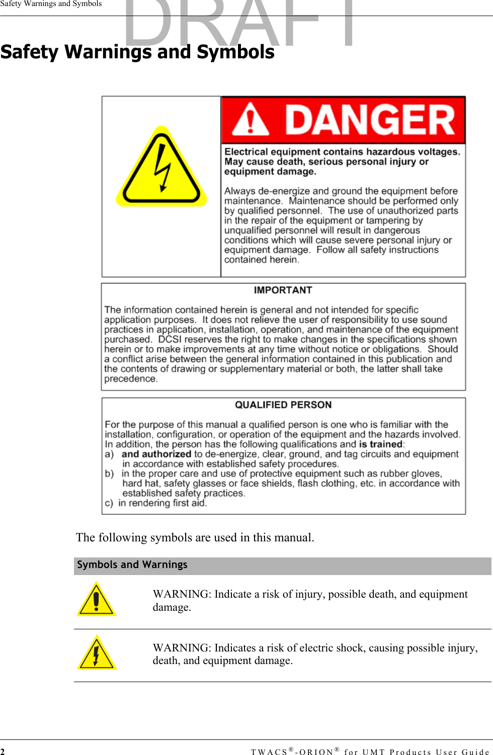

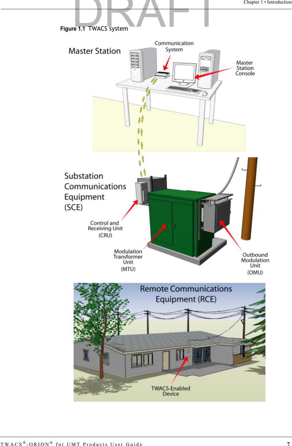

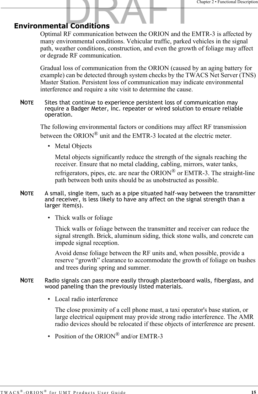
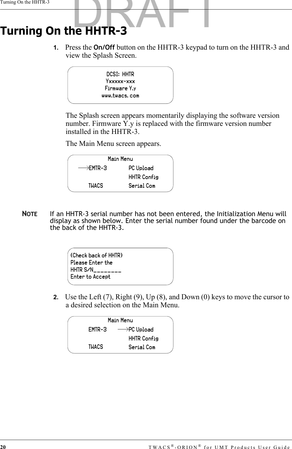
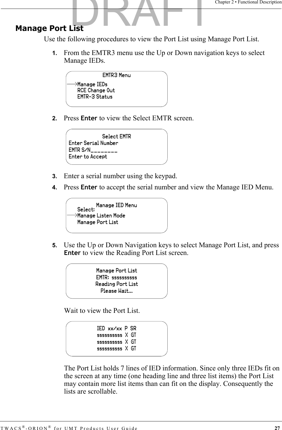
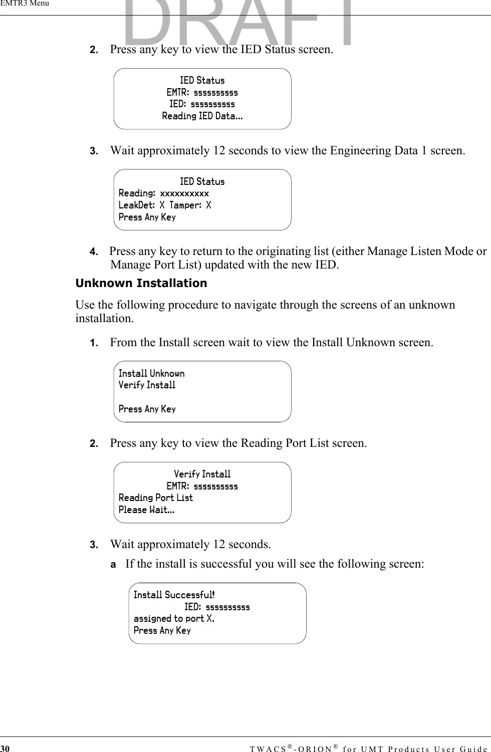
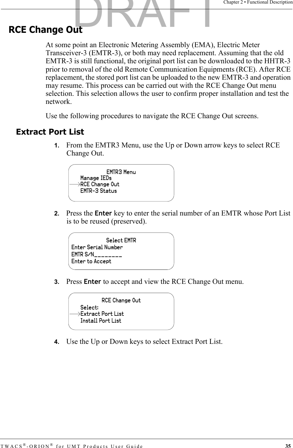
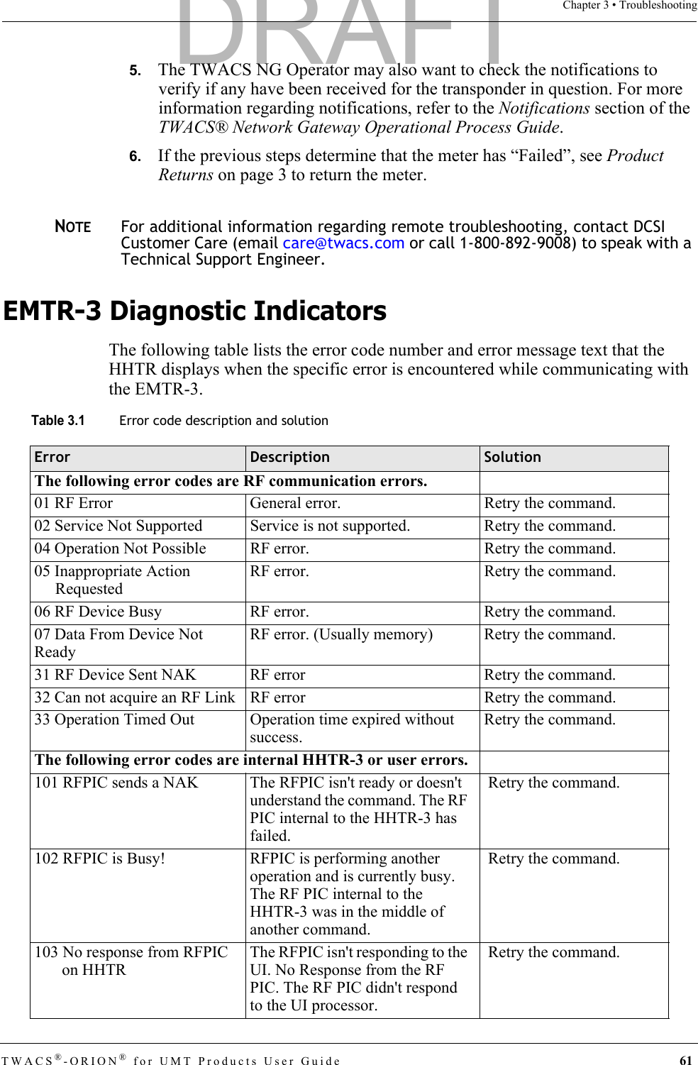
![TWACS®-ORION® for UMT Products User Guide 59Chapter 3 • TroubleshootingField Name Field Description Valid InputMeter Number The meter number assigned by the utility. IED Serial Number.[1 – 4294967295]Serial Number TWACS Serial Number. [1 – 4294967295]Serial Port Port to which the IED is associated.[1 - 7]Premises ID Number Premises ID assigned by utility, for the Port of interest (1-7).String (20)Port District Number District Number Assigned by Utility.[0 – 999999]Port District Location Location Identifier of the meter assigned by the utility.String(5)Active Flag A flag to identify that the device is active.Y, NDevice Type IED Service Type0 = Electric1 = Water2 = Gas3 = Propane4 = Other0, 1, 2, 3, 4Port User 1 A field assigned by the utility or DCSI for grouping purposes. May be blank.String(16)Port User 2 A field assigned by the utility or DCSI for grouping purposes. May be blank.String(16)Customer Account Number Customer account assigned by the utility.String(20)Rate Class The rate class assigned by the utility.String(8)Meter Type The meter type to associate with the conversion table. The system uses a default if left blank.String(10)Route ID The Route ID associated with the meter assigned by the utility.String(8)Cycle Number The cycle number for the AMR assigned by the utility.[0 – 999]Meter User 1 A field assigned by the utility or DCSI for grouping purposes. May be blank.String(16)Meter User 2 A field assigned by the utility or DCSI for grouping purposes. May be blank.String(16)DRAFT](https://usermanual.wiki/Aclara-Power-Line-Systems/Y72553-1/User-Guide-829637-Page-67.png)
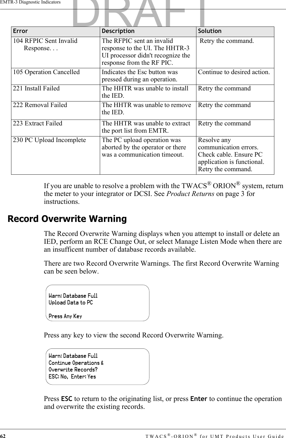
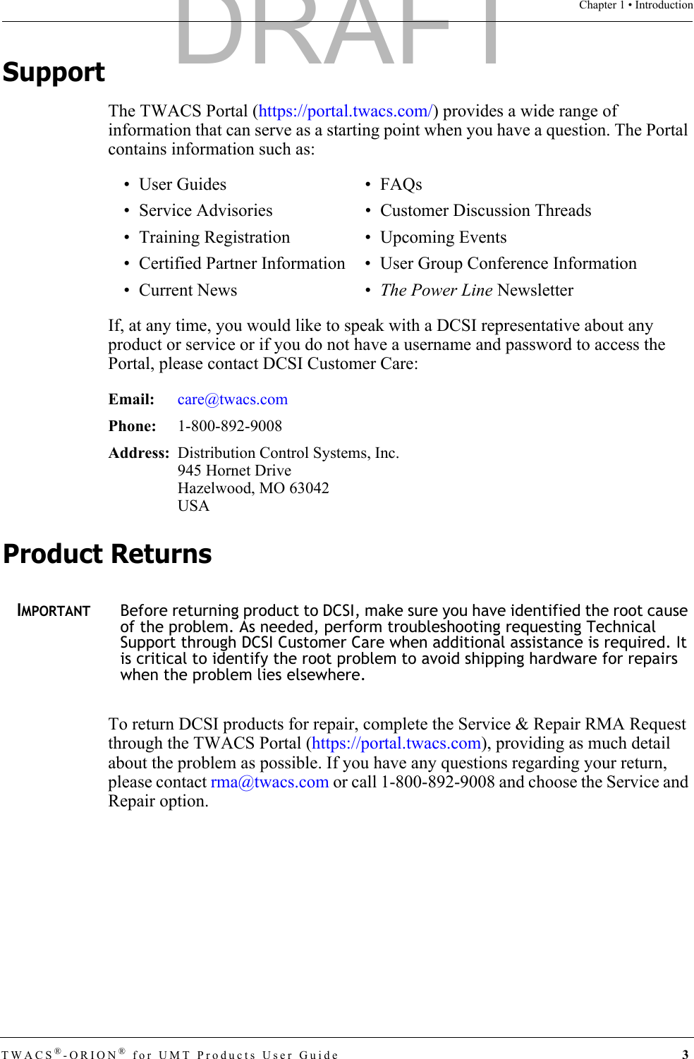
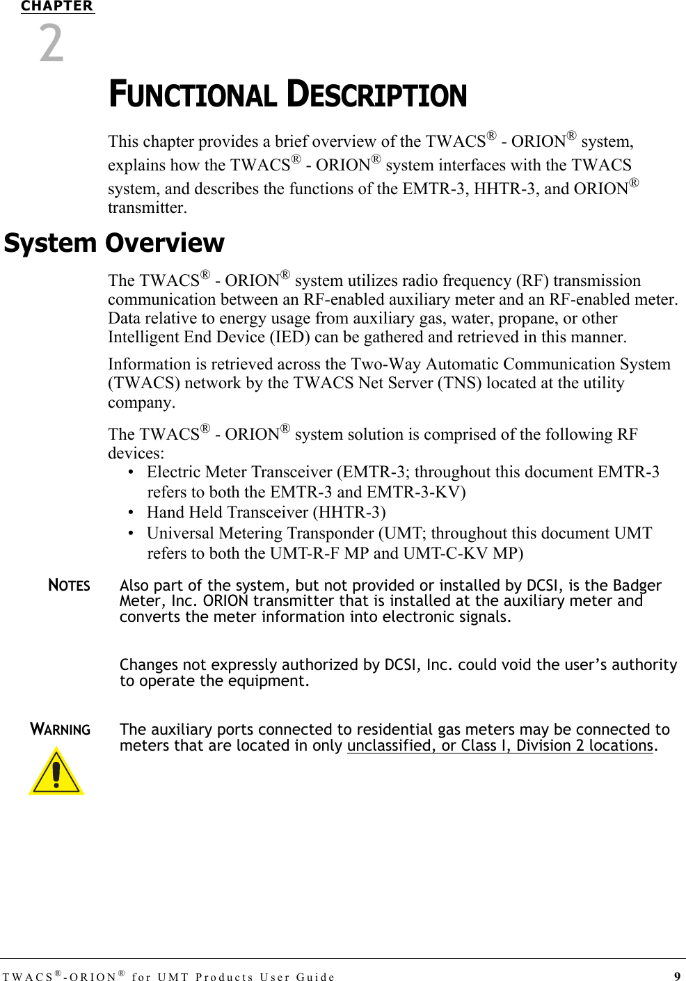
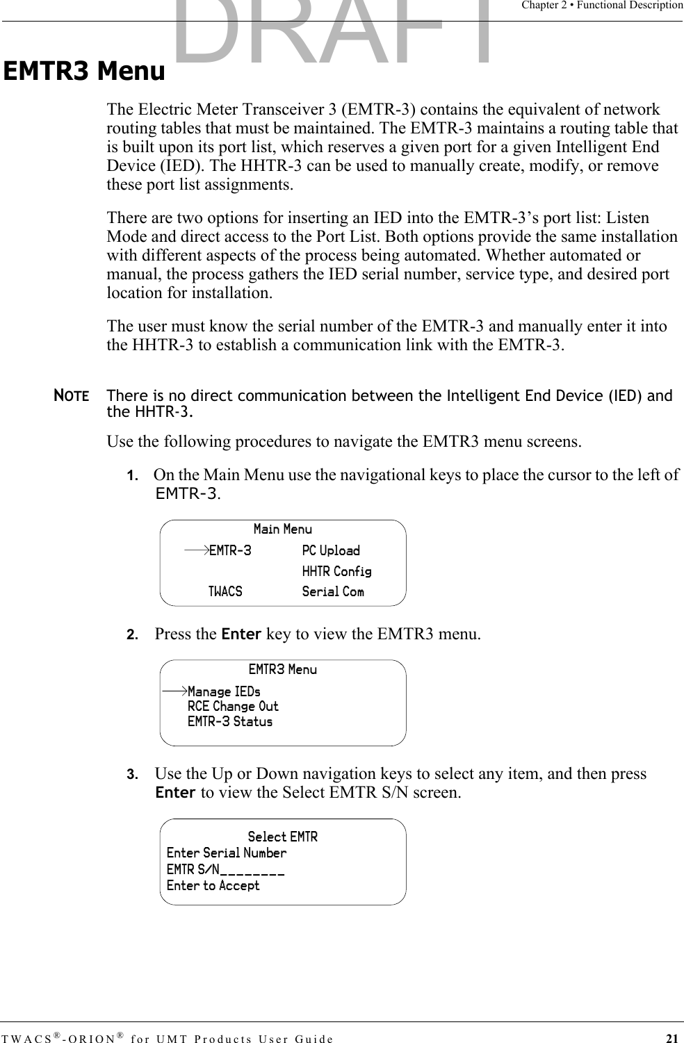
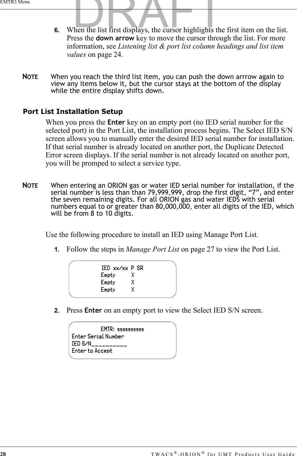
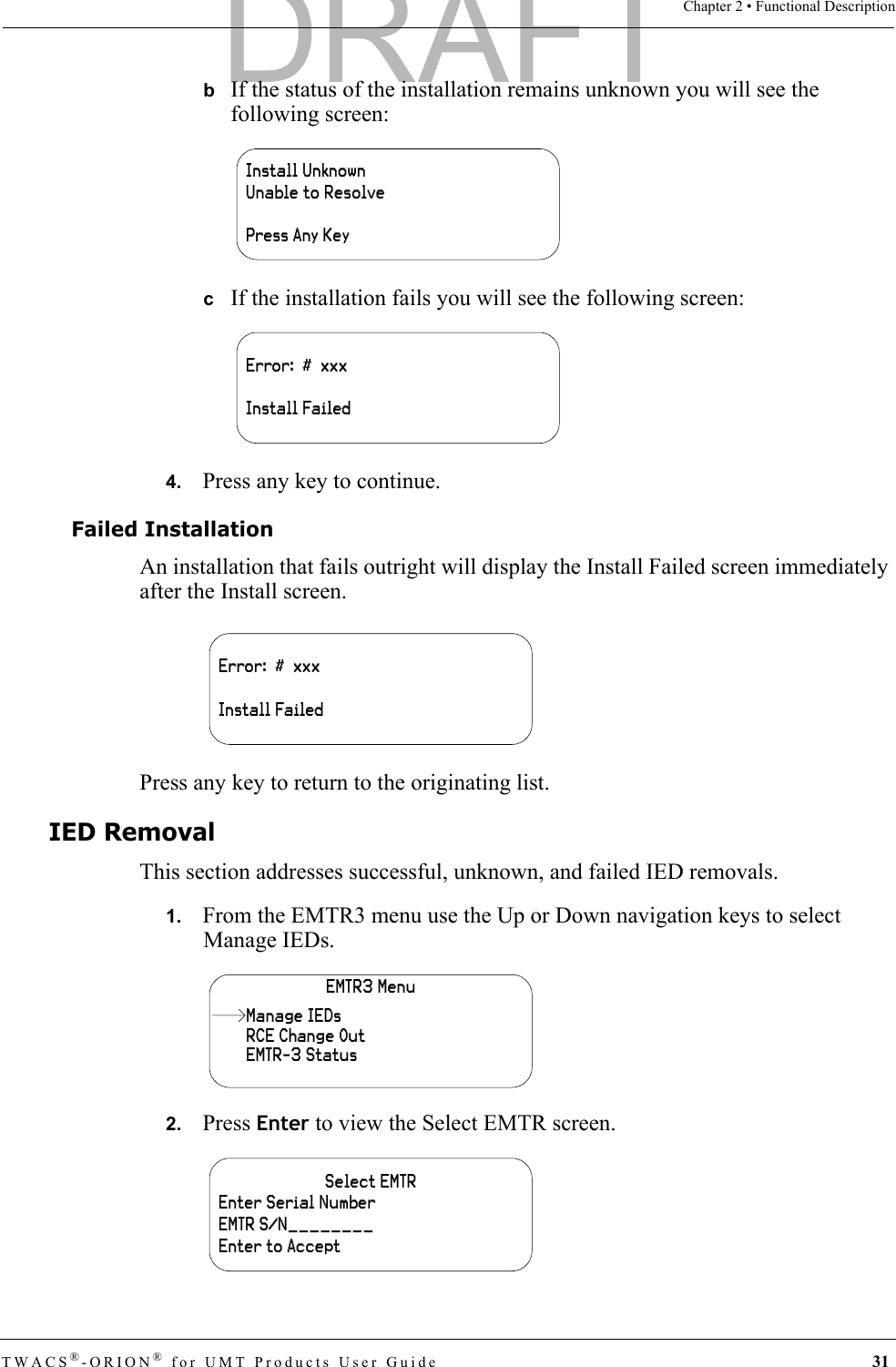
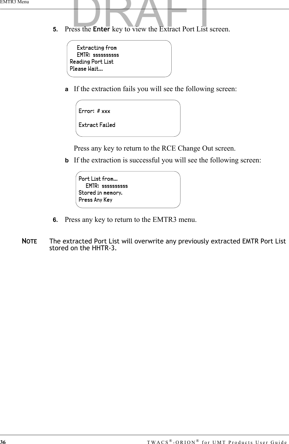
![60 TWACS®-ORION® for UMT Products User GuidePerforming Remote Analysis (TWACS NG)Performing Remote Analysis (TWACS NG)Complete the following steps to determine if a field visit is required for an unresponsive meter. You can end the procedure at any step and correct the problem when a cause of failure is determined.1. If communication fails to the transponder, check the path and search state of the transponder. You may do this by going to System Monitoring > Edit Path > Search States.2. Type in the serial number of the transponder and click Lookup.If the transponder is currently in the New, Lost or Tentative path state, the the TWACS NG will need to search the transponder. The TWACS NG Operator will need to be sure that it is in a search state of Ready. The search batch job should automatically pick up the transponder for search when the next job runs.3. If the transponder is in a Good/Done state, the TWACS NG Operator may issue a ping to the transponder. You may do this by going to System Monitoring > Test Transponder screen.4. Type in the serial number or Meter/End Device ID and click Ping.If the ping is successful, communication to the transponder is successful and has been verified. If the transponder is still not functioning as expected, a field visit will most likely be necessary.Meter Number The meter number assigned by the utility. IED Serial Number.[1 – 4294967295]Serial Number TWACS Serial Number. [1 – 4294967295]Serial Port Port to which the IED is associated.[1 - 7]Premises ID Number Premises ID assigned by utility, for the Port of interest (1-7).String (20)Port District Number District Number Assigned by Utility.[0 – 999999]Port District Location Location Identifier of the meter assigned by the utility.String(5)Active Flag A flag to identify that the device is active.Y, NDevice Type IED Service Type0 = Electric1 = Water2 = Gas3 = Propane4 = Other0, 1, 2, 3, 4Field Name Field Description Valid InputDRAFT](https://usermanual.wiki/Aclara-Power-Line-Systems/Y72553-1/User-Guide-829637-Page-68.png)