Aclara Power Line Systems Y72553-1 Metering transponder User Manual HHTR
Aclara Power-Line Systems Inc. Metering transponder HHTR
User Manual

TWACS - ORION For UMT Products
USER GUIDE Y20100-TUM (Rev A)
RR
DRAFT
DRAFT

TWACS®-ORION® for UMT Products User Guide ( Y20100)
Proprietary Notice
Information contained in this document is private to Distribution Control Systems, Inc., St. Louis, Missouri (DCSI).
This information may not be published, reproduced, or otherwise disseminated without the express written
authorization of DCSI.
Any software or firmware described in this document is furnished under a license and may be used or copied only in
accordance with the terms of such license.
Disclaimer
The information in this document is subject to change without notice and should not be construed as a commitment
by DCSI. DCSI assumes no responsibility for any errors that may appear in this document.
No responsibility is assumed for the use or reliability of software on equipment that is not supplied by DCSI.
Trademark Information
TWACS, the TWACS logo, and the DCSI logo are registered trademarks of Distribution Control Systems, Inc., St.
Louis, Mo.
Windows and Microsoft are registered trademarks of Microsoft Corporation.
TWACS®
Two-Way Automatic Communication System,
a product of
Distribution Control Systems, Inc.
Confidential and Proprietary
Copyright 2005-2007. All Rights Reserved.
DRAFT
DRAFT

TWACS®-ORION® for UMT Products User Guide i
Figures and Tables iii
Chapter 1: Introduction 1
Safety Warnings and Symbols . . . . . . . . . . . . . . . . . . . . . . . 2
Support . . . . . . . . . . . . . . . . . . . . . . . . . . . . . . . . . 3
Product Returns . . . . . . . . . . . . . . . . . . . . . . . . . . . . . 3
Related Documentation . . . . . . . . . . . . . . . . . . . . . . . . . . 4
Let Us Know How We’re Doing. . . . . . . . . . . . . . . . . . . . . . . 5
TWACS System Overview . . . . . . . . . . . . . . . . . . . . . . . . . 6
Chapter 2: Functional Description 9
System Overview . . . . . . . . . . . . . . . . . . . . . . . . . . . . . 9
Electric Meter Transceiver (EMTR-3) . . . . . . . . . . . . . . . . . . . 12
Badger Meter, Inc. ORION® Transmitter . . . . . . . . . . . . . . . . . . 13
Hand Held Tranceiver - 3 (HHTR-3) . . . . . . . . . . . . . . . . . . . . 14
RF Hardware Installation . . . . . . . . . . . . . . . . . . . . . . . . . 14
Pre-Installation Field Survey . . . . . . . . . . . . . . . . . . . . . . . 14
Environmental Conditions . . . . . . . . . . . . . . . . . . . . . . . 15
Hand Held Transceiver-3 (HHTR-3) Keypad . . . . . . . . . . . . . . . . . 17
Navigating the HHTR-3 Screens . . . . . . . . . . . . . . . . . . . . . . 18
Display Contrast . . . . . . . . . . . . . . . . . . . . . . . . . . . 18
Escape Button Functionality . . . . . . . . . . . . . . . . . . . . . . 18
HHTR-3 Menus . . . . . . . . . . . . . . . . . . . . . . . . . . . . . 19
Turning On the HHTR-3 . . . . . . . . . . . . . . . . . . . . . . . . . . 20
EMTR3 Menu . . . . . . . . . . . . . . . . . . . . . . . . . . . . . . . 21
Manage Intelligent End Devices (IEDs) . . . . . . . . . . . . . . . . . . . 23
Manage Listen Mode. . . . . . . . . . . . . . . . . . . . . . . . . . 23
Manage Port List . . . . . . . . . . . . . . . . . . . . . . . . . . . 27
Installation Results . . . . . . . . . . . . . . . . . . . . . . . . . . 29
IED Removal . . . . . . . . . . . . . . . . . . . . . . . . . . . . . 31
RCE Change Out . . . . . . . . . . . . . . . . . . . . . . . . . . . . 35
Extract Port List . . . . . . . . . . . . . . . . . . . . . . . . . . . 35
Install Port List . . . . . . . . . . . . . . . . . . . . . . . . . . . . 37
EMTR-3 Status . . . . . . . . . . . . . . . . . . . . . . . . . . . . . 39
PC Upload Menu . . . . . . . . . . . . . . . . . . . . . . . . . . . . . 40
HHTR Config Menu . . . . . . . . . . . . . . . . . . . . . . . . . . . . 42
Setup . . . . . . . . . . . . . . . . . . . . . . . . . . . . . . . . . 42
Audio . . . . . . . . . . . . . . . . . . . . . . . . . . . . . . . . 42
I/O Status . . . . . . . . . . . . . . . . . . . . . . . . . . . . . . 43
RF RMT . . . . . . . . . . . . . . . . . . . . . . . . . . . . . . . 43
Com Logic . . . . . . . . . . . . . . . . . . . . . . . . . . . . . . 44
RF Time . . . . . . . . . . . . . . . . . . . . . . . . . . . . . . . 44
Power . . . . . . . . . . . . . . . . . . . . . . . . . . . . . . . . . 45
Power Off Time. . . . . . . . . . . . . . . . . . . . . . . . . . . . 45
LCD Backlight Time . . . . . . . . . . . . . . . . . . . . . . . . . . 46
Battery Status . . . . . . . . . . . . . . . . . . . . . . . . . . . . 46
Status . . . . . . . . . . . . . . . . . . . . . . . . . . . . . . . . . 47
Table of Contents
DRAFT

ii TWACS®-ORION® for UMT Products User Guide
Table of Contents
Diags. . . . . . . . . . . . . . . . . . . . . . . . . . . . . . . . . . 48
Test Memory . . . . . . . . . . . . . . . . . . . . . . . . . . . . . 48
Test Keypad/LCD . . . . . . . . . . . . . . . . . . . . . . . . . . . 49
Test I/O & RS232 . . . . . . . . . . . . . . . . . . . . . . . . . . . 50
TWACS Menu . . . . . . . . . . . . . . . . . . . . . . . . . . . . . . . 51
HRTS. . . . . . . . . . . . . . . . . . . . . . . . . . . . . . . . . . 51
TWACS Modem . . . . . . . . . . . . . . . . . . . . . . . . . . . . . 52
Serial Com Menu . . . . . . . . . . . . . . . . . . . . . . . . . . . . . 53
Chapter 3: Troubleshooting 55
Performing Remote Analysis (TNS) . . . . . . . . . . . . . . . . . . . . . 55
Port Specific Status Information . . . . . . . . . . . . . . . . . . . . . 57
IED Configuration Data Files . . . . . . . . . . . . . . . . . . . . . . . 58
Performing Remote Analysis (TWACS NG) . . . . . . . . . . . . . . . . . . 60
EMTR-3 Diagnostic Indicators . . . . . . . . . . . . . . . . . . . . . . . 61
Record Overwrite Warning . . . . . . . . . . . . . . . . . . . . . . . . 62
Field Troubleshooting. . . . . . . . . . . . . . . . . . . . . . . . . . . 63
Meter Shop Test System. . . . . . . . . . . . . . . . . . . . . . . . . . 64
Chapter 4: Specifications 65
Electrical Specifications . . . . . . . . . . . . . . . . . . . . . . . . . 65
Electrical Ratings . . . . . . . . . . . . . . . . . . . . . . . . . . . . 65
Compliance Specifications . . . . . . . . . . . . . . . . . . . . . . . . 66
Environmental Specifications . . . . . . . . . . . . . . . . . . . . . . . 67
Physical Specifications . . . . . . . . . . . . . . . . . . . . . . . . . . 67
Additional Regulatory Data . . . . . . . . . . . . . . . . . . . . . . . . 69
Acronyms 71
Glossary 73
Index 77
DRAFT

TWACS®-ORION® for UMT Products User Guide iii
Figure 1.1 TWACS system . . . . . . . . . . . . . . . . . . . . . . . . . . . . . . . . . . . .7
Figure 2.1 RF operation block diagram. . . . . . . . . . . . . . . . . . . . . . . . . . . 11
Figure 2.2 Electric Meter Transceiver (EMTR-3) . . . . . . . . . . . . . . . . . . . . . 12
Figure 2.3 ORION transmitters for water, gas, and remote. . . . . . . . . . . . . . 13
Table 2.1 ORION transmitter specifications . . . . . . . . . . . . . . . . . . . . . . . 13
Figure 2.4 Hand Held Transceiver keypad functions . . . . . . . . . . . . . . . . . . 17
Table 2.2 HHTR-3 screen navigation buttons . . . . . . . . . . . . . . . . . . . . . . 18
Table 2.3 Escape key - menu mapping . . . . . . . . . . . . . . . . . . . . . . . . . . 18
Table 2.4 Listening list & port list column headings and list item values . . . . 24
Table 3.1 Error code description and solution. . . . . . . . . . . . . . . . . . . . . . 61
Table 4.1 Electrical ratings . . . . . . . . . . . . . . . . . . . . . . . . . . . . . . . . . . 65
Table 4.2 Compliance specifications . . . . . . . . . . . . . . . . . . . . . . . . . . . . 66
Table 4.3 Environmental specifications . . . . . . . . . . . . . . . . . . . . . . . . . . 67
Table 4.4 Physical specifications . . . . . . . . . . . . . . . . . . . . . . . . . . . . . . 67
Figures and Tables
DRAFT

iv TWACS®-ORION® for UMT Products User Guide
Figures and Tables
DRAFT

TWACS®-ORION® for UMT Products User Guide 1
CHAPTER
1
I
NTRODUCTION
This chapter contains general information about this manual, important safety
warnings to observe when using this product, contact information to receive
support, and an overview of the TWACS system.
DRAFT
2TWACS®-ORION® for UMT Products User Guide
Safety Warnings and Symbols
Safety Warnings and Symbols
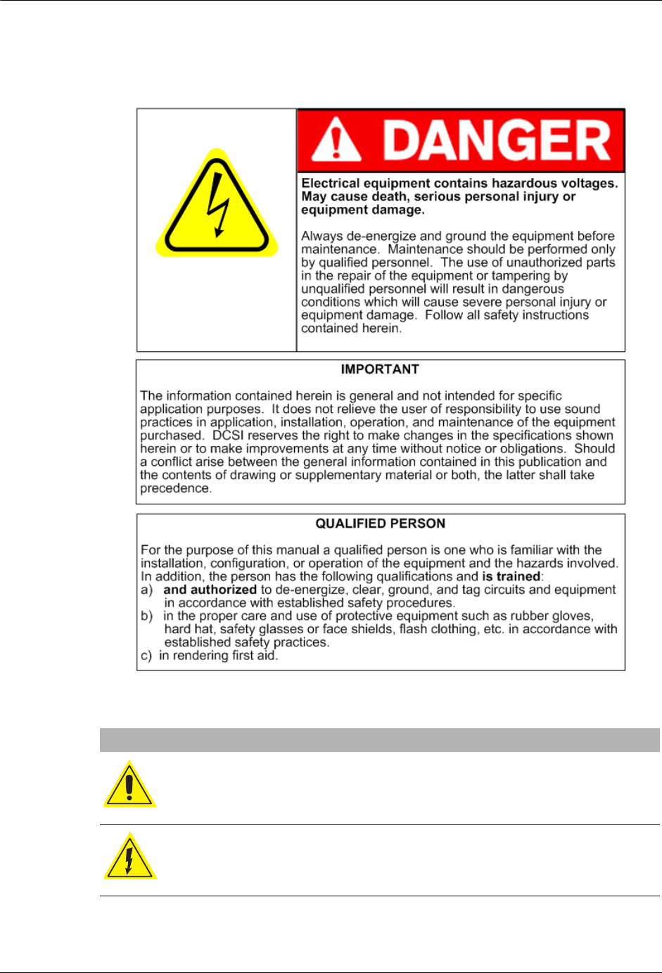
The following symbols are used in this manual.
Symbols and Warnings
WARNING: Indicate a risk of injury, possible death, and equipment
damage.
WARNING: Indicates a risk of electric shock, causing possible injury,
death, and equipment damage.
DRAFT

TWACS®-ORION® for UMT Products User Guide 3
Chapter 1 • Introduction
Support
The TWACS Portal (https://portal.twacs.com/) provides a wide range of
information that can serve as a starting point when you have a question. The Portal
contains information such as:
If, at any time, you would like to speak with a DCSI representative about any
product or service or if you do not have a username and password to access the
Portal, please contact DCSI Customer Care:
Product Returns
I
MPORTANT
Before returning product to DCSI, make sure you have identified the root cause
of the problem. As needed, perform troubleshooting requesting Technical
Support through DCSI Customer Care when additional assistance is required. It
is critical to identify the root problem to avoid shipping hardware for repairs
when the problem lies elsewhere.
To return DCSI products for repair, complete the Service & Repair RMA Request
through the TWACS Portal (https://portal.twacs.com), providing as much detail
about the problem as possible. If you have any questions regarding your return,
please contact rma@twacs.com or call 1-800-892-9008 and choose the Service and
Repair option.
•User Guides •FAQs
• Service Advisories • Customer Discussion Threads
• Training Registration • Upcoming Events
• Certified Partner Information • User Group Conference Information
• Current News • The Power Line Newsletter
Email: care@twacs.com
Phone: 1-800-892-9008
Address: Distribution Control Systems, Inc.
945 Hornet Drive
Hazelwood, MO 63042
USA
DRAFT

4TWACS®-ORION® for UMT Products User Guide
Related Documentation
Related Documentation
The following publications are referenced in this manual. The documents listed
below plus the latest version of all other DCSI technical publications are available
through the TWACS Portal (https://portal.twacs.com/).
HHTR-PC Application Help
Provides all the necessary details for transferring Intelligent End Device (IED)
installation and removal data from an HHTR-3 unit to a PC and formatting that
data for export to the Master Station (MS) or to a utility’s Meter Data
Management (MDM) system. Access the Help through the HHTR-PC
Application software interface. The Help is not available through the TWACS
Portal.
Meter Shop Test System Help
Provides all the necessary details required for testing TWACS-enabled devices
with the Meter Shop Test Tool software. Access the Help through the Meter Shop
Test Tool software interface. The Help is not available through the TWACS
Portal.
Meter Shop Test System Set-Up Guide (Y10030TM)
Provides information that enables you to test TWACS-enabled devices for
TWACS signaling response, read select transponder registers, zero select
transponder registers, and perform various other transponder functions.
Portable RCE Test Unit Technical Manual (Y103127-3TM)
Ships with the Portable RCE Test Unit. Includes detailed product specifications
and operating instructions.
TNS End User Guide (Y10285TM)
Serves as a companion manual to the TNS Operational Process Guide. While the
TNS Operational Process Guide provides high-level process and procedure
recommendations for obtaining optimum results from your TWACS system, the
TNS End User Guide provides the detailed procedures, and form field and
application definitions, that enable you to perform the functions found in the
process manual.
TNS Operational Process Guide (Y10352TM)
Presents high-level procedures and processes for operating your TWACS system,
through the TNS interface. These processes and procedures span a number of
application sets, and are organized around functions such as reading meters,
substation setup, and operating TNS.
Transponder Type and Model Matrix (Y10598-TEB)
Provides a listing of transponders, transponder types, and applicable meter
models.
DRAFT

TWACS®-ORION® for UMT Products User Guide 5
Chapter 1 • Introduction
TWACS® Network Gateway Operational Process Guide
Includes procedures and processes for operating your TWACS system through
the TWACS® NG interface. The information spans a number of application sets,
and are organized around functions such as reading meters, substation setup, and
operating TWACS NG.
TWACS® NG System Help
Built into the TWACS® NG interface, topic and index-searchable online system
help is available. Access the Help through the software interface. The Help is not
available through the TWACS Portal.
Universal Metering Transponder for FOCUS® Meter User Guide
(Y10574-TUM)
Provides a functional description, as well as troubleshooting information and
technical specifications for the UMT-FOCUS transponder.
Universal Metering Transponder for kV2c Meter User Guide (Y10577-TUM)
Provides a functional description, as well as troubleshooting information and
technical specifications for the UMT-C-KV transponder.
Let Us Know How We’re Doing
In an ongoing effort to produce effective documentation, the Technical
Publications department at DCSI welcomes any feedback you can offer regarding
this manual.
Please relay feedback, including suggestions for improvement or to alert us to
corrections, by sending an email to techpubs@twacs.com or calling Customer
Care at 1-800-892-9008.
DRAFT

6TWACS®-ORION® for UMT Products User Guide
TWACS System Overview
TWACS System Overview
The TWACS system is a fixed network, utility communication system. Running at
a centralized location, the TWACS operating software communicates with end
points, such as meters, by way of existing power lines. The TWACS system allows
full two-way access to and from the consumer’s meter, providing communication
and control features for the Utility.
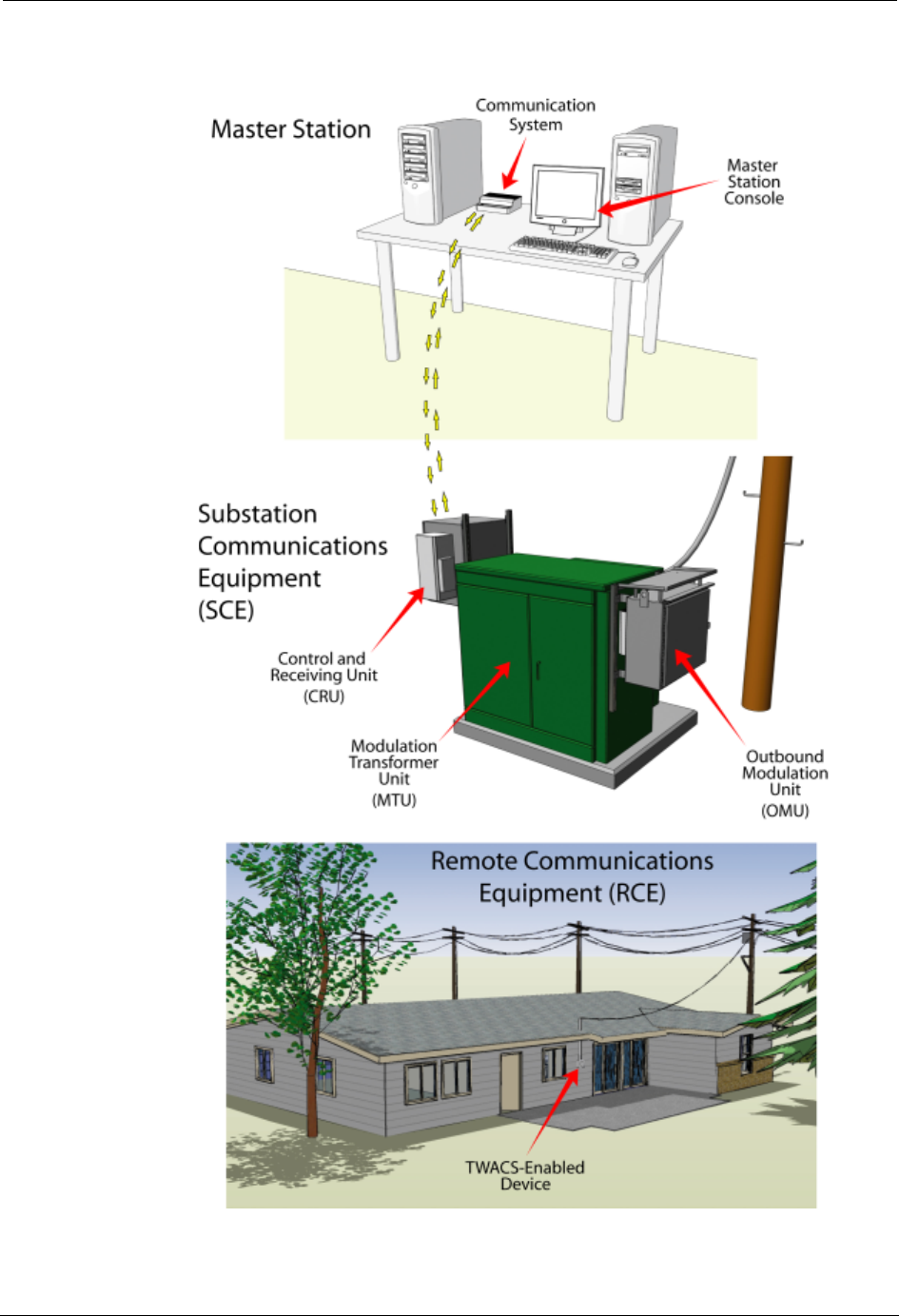
The TWACS system consists of three levels of components (see Figure 1.1):
• Master Station (MS)
The Master Station TWACS operating software, either TWACS Net Server
(TNS) or TWACS® Network Gateway (TWACS NG), is the chief
component of the entire Two-Way Automatic Communication System
(TWACS). The Master Station software manages all collected metering and
interval data as well as the connection between the utility and the consumer’s
premises. TNS is DCSI’s standard solution while TWACS NG is available
for very large deployments requiring a high volume of readings for
time-of-use or critical peak pricing programs.
The primary functions of TNS and TWACS NG are:
•Managing the TWACS system communication network.
•Supporting applications such as metering, troubleshooting, outage
detection, and load control.
•Collecting remote meter data for the database server, which forwards the
data to a third-party utility software application.
TNS and TWACS NG are part of the corporate enterprise network. The
system is based on the Oracle® database, which is an open system, meaning
it can interact and inter-operate with other applications on local and remote
systems, on a variety of hardware platforms, and in a number of software
environments. The system provides the user interfaces for configuring the
necessary parameters to retrieve and send data.
• Substation Communications Equipment (SCE)
• Remote Communications Equipment (RCE)
This is the level at which the meter transponder resides within the electric
meter.
As shown in Figure 1.1, outbound messages originate in the Master Station and
pass through the substation to the transponder (RCE). Inbound meter data is sent
from the transponder to the SCE, where it is decoded and then sent to the Master
Station for analysis or bill file creation.
DRAFT
TWACS®-ORION® for UMT Products User Guide 7
Chapter 1 • Introduction
Figure 1.1
TWACS system
DRAFT

8TWACS®-ORION® for UMT Products User Guide
TWACS System Overview
DRAFT

TWACS®-ORION® for UMT Products User Guide 9
CHAPTER
2
F
UNCTIONAL
D
ESCRIPTION
This chapter provides a brief overview of the TWACS® - ORION® system,
explains how the TWACS® - ORION® system interfaces with the TWACS
system, and describes the functions of the EMTR-3, HHTR-3, and ORION®
transmitter.
System Overview
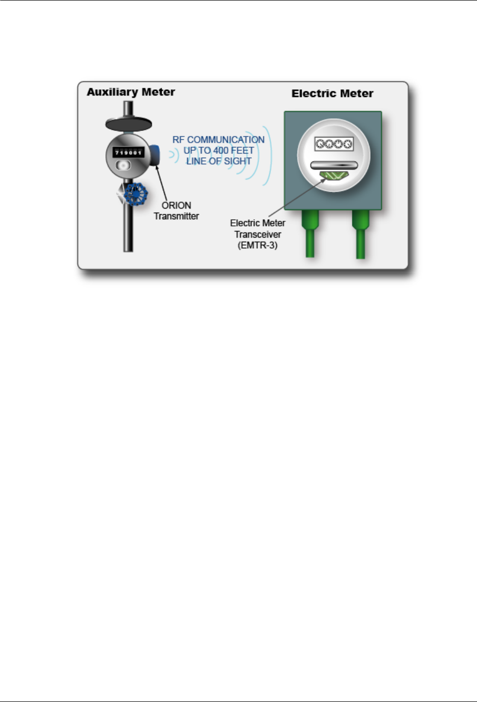
The TWACS® - ORION® system utilizes radio frequency (RF) transmission
communication between an RF-enabled auxiliary meter and an RF-enabled meter.
Data relative to energy usage from auxiliary gas, water, propane, or other
Intelligent End Device (IED) can be gathered and retrieved in this manner.
Information is retrieved across the Two-Way Automatic Communication System
(TWACS) network by the TWACS Net Server (TNS) located at the utility
company.
The TWACS® - ORION® system solution is comprised of the following RF
devices:
• Electric Meter Transceiver (EMTR-3; throughout this document EMTR-3
refers to both the EMTR-3 and EMTR-3-KV)
• Hand Held Transceiver (HHTR-3)
• Universal Metering Transponder (UMT; throughout this document UMT
refers to both the UMT-R-F MP and UMT-C-KV MP)
N
OTES
Also part of the system, but not provided or installed by DCSI, is the Badger
Meter, Inc. ORION transmitter that is installed at the auxiliary meter and
converts the meter information into electronic signals.
Changes not expressly authorized by DCSI, Inc. could void the user’s authority
to operate the equipment.
W
ARNING
The auxiliary ports connected to residential gas meters may be connected to
meters that are located in only unclassified, or Class I, Division 2 locations.
DRAFT
10 TWACS®-ORION® for UMT Products User Guide
System Overview
RF communication links the ORION (located at the auxiliary meter) to the
EMTR-3 (located inside a nearby electric meter.) This communication enables
successful operation of the Automatic Meter Reading (AMR) system.
The TWACS® - ORION®system operates in the 902 - 928 MHz Industrial/
Scientific/Medical frequency band. The Badger ORION devices periodically
transmit bursts of digital data containing meter reading information on a requency
of 916.45 MHz. These are one way transmissions, sent as a two millisecond burst
every four to five seconds, and are field strength limited under section 15.249 of
FCC regulations. The EMTR-3 devices are manufactured by DCSI and recieve
transmissions from any ORION devices within range that have been assigned to
that EMTR-3. The EMTR-3 then passes the data to the UMT-R-F MP or
UMT-C-KV MP TWACS transponder. When requested by the utility, the meter
data is returned using the TWACS power line communications system.
The HHTR-3 is a tool used by an installer to set up and configure the EMTR-3 to
listen for transmissions from specific ORION devices. It also maintains a record of
installation activities which may be downloaded to a PC via hardware link at the
end of the day.
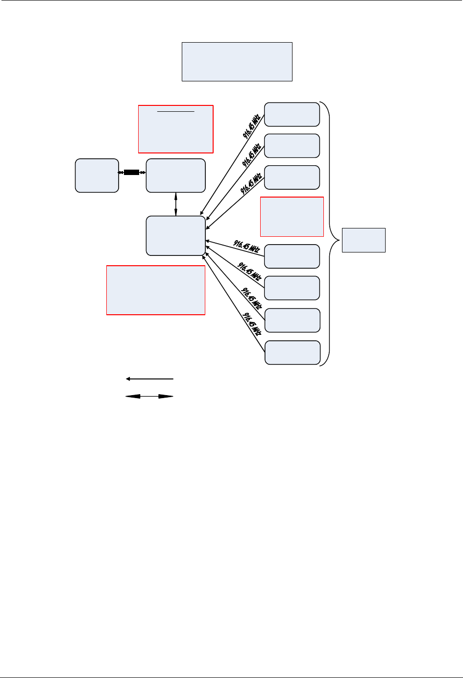
The following block diagram summarizes the interfaces and communications
between the system components.
DRAFT
TWACS®-ORION® for UMT Products User Guide 11
Chapter 2 • Functional Description
Figure 2.1
RF operation block diagram
During the installation and configuration process, the HHTR-3 and EMTR-3 use
one or more of 51 channels spaced 322 kHz apart in the 902-928 MHz band to
intercommunicate with each other. Control commands and data are input to the
HHTR-3 via the keypad by the installation operator and passed to the EMTR-3
over the RF link. The EMTR-3 acknowledges transmissions from the HHTR-3 and
can read back internally stored data for confirmation of receipt. EMTR-3
transmission occurs only when data is sent or requested by the HHTR-3.
Frequency channel selection is controlled by the HHTR software and is not
operator selectable. Both the HHTR-3 and EMTR-3 operate as intentional radiators
under Section 15.249 of FCC regulations, with transmitted field strengths limited
to less than 94 dBuV/meter. These units use frequency shift-keyed digital data at
9600 bps to communicate, and no subcarriers are used. The occupied bandwidth of
the EMTR-3 or HHTR-3 transmissions is 200 kHz. Both the HHTR-3 and the
EMTR-3 devices have permanently atttached integral antennas and use single
integrated circuit RF transceivers.
HHTR Data
RF = PIC 18 LF242
902 - 928 MHz
UI = PIC 18 LF 6720
8 MHz
7. 2V NiMH 1600 mAH
Regulated to 5V an
d
3.3V
EMTR-3 Dat
a
Orion Dat
a
916 .45 MHz
Data Rate = 100 kbps
2-level FSK +/ - 50 Khz
(3 o
f
6)
Orion Transmitter
Orion Transmitter
HHTR
Handheld
Transceiver
PC
Data Transfer
from
/
to
HHTR
FOCUS with
EMT
R
-3
RF Interface
Orion Transmitter
Orion Transmitter
RF Operation Block Diagram
(TWACS
-Orion Project)
June 22, 2007
Wire Interface to
Water/Gas Meter
Encoder
1-
way RF Link
902- 928 MHz
Bi
-
Directional
RF Lin
k
RS- 232
Multi-port EMA provides 1 Electrical port
and 7 RF
p
orts for
g
as/water.
EMA unregulated voltage is 6V to 13V.
EMA regulated voltage is 5V.
Re
g
ulated fro
m
EMA to EMTR-3 is 3.3V.
PIC18F 4525
8MHz
F
CC
ID
:
P
N3
Y
7
2
553
-1
Orion Transmitter
Orion Transmitter
Orion Transmitter
DRAFT
12 TWACS®-ORION® for UMT Products User Guide
System Overview
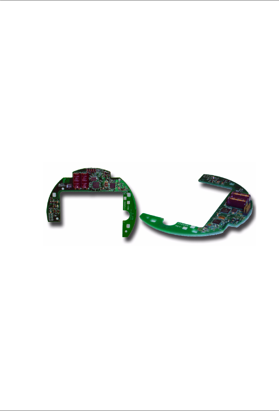
Electric Meter Transceiver (EMTR-3)
The EMTR-3 is an electronic module assembly (EMA) that is installed in a
TWACS-enabled meter. The EMTR-3 is connected to the UMT transponder
during meter/transponder integration. The EMTR-3 adds functionality to the host
UMT. It does not communicate over the power line but provides data on-command
to the UMT when queried.
The EMTR-3 can communicate with up to seven ORION® transmitters. Data from
the ORION® transmitter is relayed to the EMTR-3 at each communication session.
This data is relayed upon request to the UMT via I2C communication and is
accessed by the TNS across the TWACS network.
The EMTR-3 listens (for 2.5 seconds) for communication from an ORION®
transmitter. Then, for 2.5 seconds the EMTR-3 listens for an HHTR-3. This pattern
cycles continuously.
Figure 2.2
Electric Meter Transceiver (EMTR-3)
R
EGULATORY
D
ATA
This equipment has been tested and found to comply with the limits for a Class
B digital device, pursuant to Part 15 of the FCC Rules. These limits are
designed to provide reasonable protection against harmful interference in a
residential installation. This equipment generates, uses and can radiate radio
frequency energy and, if not installed and used in accordance with the
instructions, may cause harmful interference to radio communications.
However, there is no guaranteee that interference will not occur in a
particular installation. If this equipment does cause harmful interference to
radio or television reception, which can be determined by turning the
equipment off and on, the user is encouraged to try to correct the
interference by one or more of the following measures: reorient or reloact the
receiving antenna, increase the separation between the equipment and
receiver, connect the equipment into an output on a circuit different from
that to which the receiver is connected, consult the dealer or an experience
radio/TV technician for help.
Operation is subject to the following two conditions: (1) This device may not
cause harmful interference. and (2) this device must accept any interference
received, including interference that may cause undesired operation.
DRAFT

TWACS®-ORION® for UMT Products User Guide 13
Chapter 2 • Functional Description
Badger Meter, Inc. ORION
®
Transmitter
The DCSI RF TWACS System and the Badger Meter, Inc. ORION® transmitter
are capable of data communication. The ORION® module uses the RF bubble-up
broadcast mode to communicate (one way) from the auxiliary meter to the electric
meter. The ORION® transmitter sends customer usage data (at 100Kbps) every
five seconds on the 916.450 MHz frequency channel. The RF TWACS system
receives and processes this data via the EMTR-3 where it relays on request to the
UMT module. Then it can be retrieved by the utility across power distribution
lines.
Figure 2.3
ORION transmitters for water, gas, and remote
Specifications:
Table 2.1
ORION transmitter specifications
REMOTE
ORION
GAS
ORION
WATER
ORION
ORION
Specification Description
Power 3.6 VDC embedded battery
Functional Life Expectancy Minimum: 10 years
Expected: 15 years
Frequency 916.450 MHz
Data Communications Burst mode fixed length
packet, simplex
Data Format 3-of-6
Data Rate 100 Kbps + 1 Kbps
Data Encryption None
Modulation Frequency Shift Keying (FSK)
Packet Encoding Non Return to Zero (NRZ)
DRAFT

14 TWACS®-ORION® for UMT Products User Guide
RF Hardware Installation
Hand Held Tranceiver - 3 (HHTR-3)
The DCSI Hand Held Transceiver - (HHTR-3) is used to configure and setup the
EMTR-3 (installed in the electric meter). The HHTR-3 is used to establish the
communication link between the EMTR-3 and the ORION® transmitter and can be
used to test the radio link.
RF Hardware Installation
This section provides instructions for installing the RF hardware on-site. A
functioning network can be created and its functionality verified before leaving the
site.
Pre-Installation Field Survey
The field survey is used to review the environmental conditions present at any
particular location and lay out the system to maximize performance. DCSI
recommends that you conduct a field survey before performing the actual hardware
installation.
As with all RF devices, certain environmental conditions must be present to
optimize RF communications. Be aware of the factors that affect the radio
transmission between the ORION and the EMTR-3 when performing the field
survey, such as:
• Metal objects
• Thick walls or foliage
• Local radio interference
• Position of the ORION and/or EMTR-3
Factor in all environmental conditions when planning the location of the
meter/EMTR-3 assembly.
N
OTE
A clear line of sight between the ORION transmitter and receiver is preferred,
but is not always attainable.
The following section discusses the environmental conditions that may affect RF
transmissions between the ORION and EMTR-3.
Channels Single channel (43A)
Range 400 ft. clear line of sight -
affected by installation and
conditions; less if pit installed
ORION
DRAFT

TWACS®-ORION® for UMT Products User Guide 15
Chapter 2 • Functional Description
Environmental Conditions
Optimal RF communication between the ORION and the EMTR-3 is affected by
many environmental conditions. Vehicular traffic, parked vehicles in the signal
path, weather conditions, construction, and even the growth of foliage may affect
or degrade RF communication.
Gradual loss of communication from the ORION (caused by an aging battery for
example) can be detected through system checks by the TWACS Net Server (TNS)
Master Station. Persistent loss of communication may indicate environmental
interference and require a site visit to determine the cause.
N
OTE
Sites that continue to experience persistent loss of communication may
require a Badger Meter, Inc. repeater or wired solution to ensure reliable
operation.
The following environmental factors or conditions may affect RF transmission
between the ORION® unit and the EMTR-3 located at the electric meter.
• Metal Objects
Metal objects significantly reduce the strength of the signals reaching the
receiver. Ensure that no metal cladding, cabling, mirrors, water tanks,
refrigerators, pipes, etc. are near the ORION® or EMTR-3. The straight-line
path between both units should be as unobstructed as possible.
N
OTE
A small, single item, such as a pipe situated half-way between the transmitter
and receiver, is less likely to have any affect on the signal strength than a
larger item(s).
• Thick walls or foliage
Thick walls or foliage between the transmitter and receiver can reduce the
signal strength. Brick, aluminum siding, thick stone walls, and concrete can
impede signal reception.
Avoid dense foliage between the RF units and, when possible, provide a
reserve “growth” clearance to accommodate the growth of foliage on bushes
and trees during spring and summer.
N
OTE
Radio signals can pass more easily through plasterboard walls, fiberglass, and
wood paneling than the previously listed materials.
• Local radio interference
The close proximity of a cell phone mast, a taxi operator's base station, or
large electrical equipment may provide strong radio interference. The AMR
radio devices should be relocated if these objects of interference are present.
• Position of the ORION® and/or EMTR-3
DRAFT

16 TWACS®-ORION® for UMT Products User Guide
RF Hardware Installation
These are important factors in RF deployment. The ORION® antenna is
omni-directional. The signal radiates 360 degrees. The EMTR-3 antenna
alignment is parallel to the front cover of the electric meter, and is the most
sensitive RF reception surface.
Face the front of the meter/EMTR-3 toward the ORION® transmitter when
possible; even on opposite sides of a building. This allows maximum
communication surface and distance between the units. Allow for some
additional power margin in the signal strength to accommodate seasonal or
other changes in environmental conditions.
In the future, after installation, the site owner should inform you of any alterations
to the site that could affect radio performance.
DRAFT
TWACS®-ORION® for UMT Products User Guide 17
Chapter 2 • Functional Description
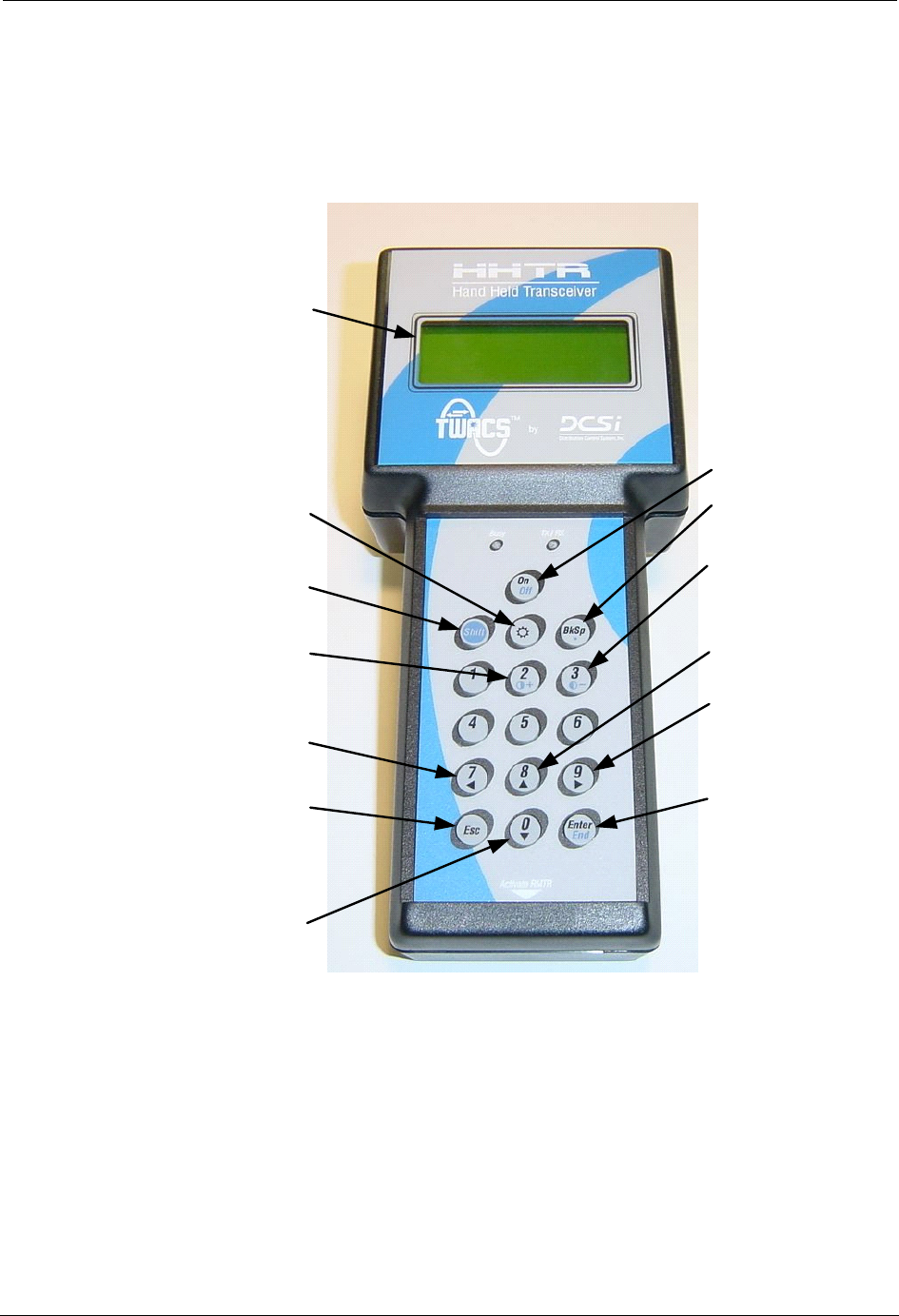
Hand Held Transceiver-3 (HHTR-3) Keypad
This section describes the HHTR-3 keypad and its use for screen navigation.
Figure 2.4
Hand Held Transceiver keypad functions
LCD
Display
On/Off
Enter/
End
Move Up
Move
Right
Decrease
Contrast
Backspace
Esc
Shift
Increase
Contrast
Move
Down
Move
Left
Backlight
DRAFT
18 TWACS®-ORION® for UMT Products User Guide
Hand Held Transceiver-3 (HHTR-3) Keypad
Navigating the HHTR-3 Screens
Use the arrow buttons to navigate through the HHTR-3 screens.
N
OTE
When pressing the 7, 8, 9, or 0 numeric button, the HHTR-3 automatically
determines whether the numeric or scroll functionality of the button is
required.
Display Contrast
Adjust the display contrast by using the number 2 and 3 buttons as follows:
• Increase the contrast - Hold down the Shift button and repeatedly press the
number 2 button.
• Decrease the contrast - Hold down the Shift button and repeatedly press the
number 3 button.
Escape Button Functionality
The Escape key in general is used to cancel an action or go to a previous menu.
•Press the Escape key once to end the current procedure and return to the
previous menu.
•Press the Escape key repeatedly to “back out” to previous menus.
The Escape key provides the menu navigation as defined in the following table.
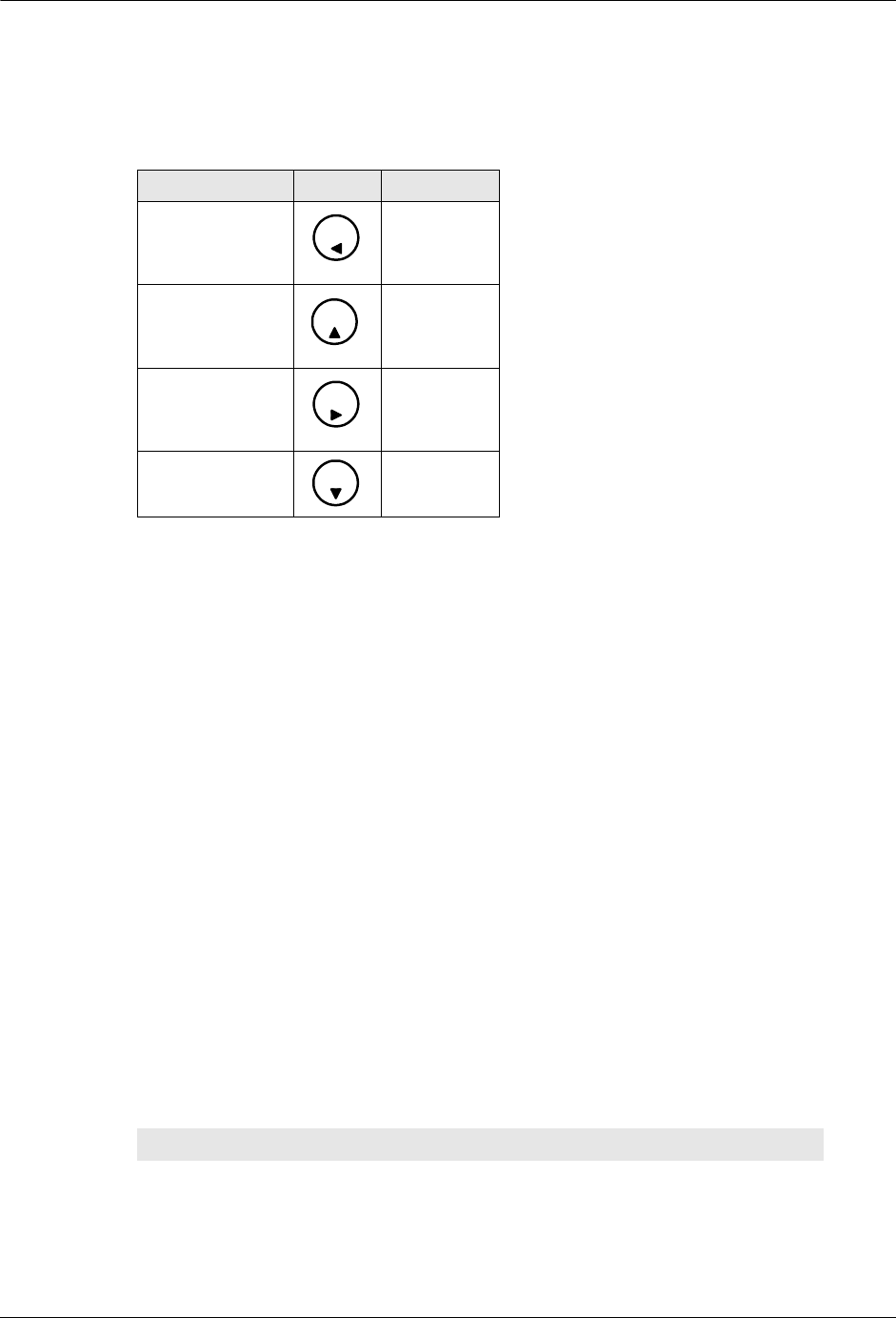
Table 2.2
HHTR-3 screen navigation buttons
Button Number Graphic Function
7Move left
8 Move up
9 Move right
0 Move down
7
8
9
0
Table 2.3
Escape key - menu mapping
Starting Menu Screen Ending Menu Screen
EMTR3 Menu Main Menu
Waiting for PC Main Menu
Select EMTR S/N EMTR3 Menu
Enter Time & Date Select EMTR S/N
DRAFT

TWACS®-ORION® for UMT Products User Guide 19
Chapter 2 • Functional Description
HHTR-3 Menus
Below is a list of the menus and selections available from the HHTR-3.
Main Menu and Sub-Menu Items
•EMTR3
•Manage IEDs
•RCE Change Out
•EMTR-3 Status
•PC Upload
• HHTR Config
•Setup
•Power
•Status
•Diags
•TWACS
•HRTS
•TWACS Modem
•Serial Com
•Baud Rate
•Display
N
OTE
If question marks (???) display instead of data, simultaneously pressing the
Backspace button and pressing 0 clears the screen.
Manage IEDs Select EMTR S/N
Starting Listening Mode Manage IEDs
Listening List Select EMTR S/N
Port List Select EMTR S/N
RCE Change Out Menu Select EMTR S/N
Port List Verification RCE Change Out Menu
Port Number Menu Listening List
Service Type Menu Port Number Menu (if Listening List)
Select IED S/N (if Port List)
Select IED S/N Port List
Table 2.3
Escape key - menu mapping
Starting Menu Screen Ending Menu Screen
Main Menu
TWACS
HHTR Config
Serial Com
PC UploadEMTR-3
DRAFT

20 TWACS®-ORION® for UMT Products User Guide
Turning On the HHTR-3
Turning On the HHTR-3
1. Press the On/Off button on the HHTR-3 keypad to turn on the HHTR-3 and
view the Splash Screen.
The Splash screen appears momentarily displaying the software version
number. Firmware Y.y is replaced with the firmware version number
installed in the HHTR-3.
The Main Menu screen appears.
N
OTE
If an HHTR-3 serial number has not been entered, the Initialization Menu will
display as shown below. Enter the serial number found under the barcode on
the back of the HHTR-3.
2. Use the Left (7), Right (9), Up (8), and Down (0) keys to move the cursor to
a desired selection on the Main Menu.
DCSI: HHTR
Yxxxxx-xxx
Firmware Y.y
www.twacs. com
Main Menu
TWACS
HHTR Config
Serial Com
PC UploadEMTR-3
(Check back of HHTR)
Please Enter the
HHTR S/N________
Enter to Accept
Main Menu
EMTR-3
TWACS
HHTR Config
Serial Com
PC Upload
DRAFT

TWACS®-ORION® for UMT Products User Guide 21
Chapter 2 • Functional Description
EMTR3 Menu
The Electric Meter Transceiver 3 (EMTR-3) contains the equivalent of network
routing tables that must be maintained. The EMTR-3 maintains a routing table that
is built upon its port list, which reserves a given port for a given Intelligent End
Device (IED). The HHTR-3 can be used to manually create, modify, or remove
these port list assignments.
There are two options for inserting an IED into the EMTR-3’s port list: Listen
Mode and direct access to the Port List. Both options provide the same installation
with different aspects of the process being automated. Whether automated or
manual, the process gathers the IED serial number, service type, and desired port
location for installation.
The user must know the serial number of the EMTR-3 and manually enter it into
the HHTR-3 to establish a communication link with the EMTR-3.
N
OTE
There is no direct communication between the Intelligent End Device (IED) and
the HHTR-3.
Use the following procedures to navigate the EMTR3 menu screens.
1. On the Main Menu use the navigational keys to place the cursor to the left of
EMTR-3.
2. Press the Enter key to view the EMTR3 menu.
3. Use the Up or Down navigation keys to select any item, and then press
Enter to view the Select EMTR S/N screen.
Main Menu
TWACS
HHTR Config
Serial Com
PC UploadEMTR-3
EMTR3 Menu
RCE Change Out
EMTR-3 Status
Manage IEDs
Select EMTR
Enter Serial Number
EMTR S/N________
Enter to Accept
DRAFT

22 TWACS®-ORION® for UMT Products User Guide
EMTR3 Menu
4. Enter the EMTR serial number using the HHTR-3 keypad and press Enter.
aUpon power-up the HHTR-3 date and time are cleared. The
HHTR-3 will automatically gather and update date and time
information from the EMTR-3 with which it is communicating.
bWhile the HHTR-3 and EMTR-3 exchange date and time
information you will see the following screen:
cIf the EMTR-3 fails to give date and time information to the
HHTR-3, you will see the following screen:
Enter the current Date and Time.
Press Enter to accept the Date and Time.
After the time and date acquisition process has been performed, the next menu
screen is displayed based on the initial selection from the EMTR-3 menu screen.
Select EMTR
Enter Serial Number
EMTR S/N________
Please Wait...
Enter Time & Date
Date: 20yy/mm/dd
Time: hh:mm:00
Enter to Accept
DRAFT

TWACS®-ORION® for UMT Products User Guide 23
Chapter 2 • Functional Description
Manage Intelligent End Devices (IEDs)
This section describes how to insert an IED into the EMTR-3’s port list using the
Manage Listen Mode or the Manage Port List.
Manage Listen Mode
Use the following procedure to view the EMTR-3’s port assignments using
Manage Listen Mode.
1. From the EMTR3 menu use the Up or Down navigation keys to select
Manage IEDs.
2. Press Enter to view the Select EMTR screen.
3. Enter a serial number using the keypad.
4. Press Enter to accept the serial number and view the Manage IED Menu.
5. Use the Up or Down Navigation keys to select Manage Listen Mode, and
press Enter to view the Starting Listen Mode screen.
EMTR3 Menu
RCE Change Out
EMTR-3 Status
Manage IEDs
Select EMTR
Enter Serial Number
EMTR S/N________
Enter to Accept
Manage IED Menu
Manage Port List
Select:
Manage Listen Mode
Manage Listen Mode
EMTR: ssssssssss
Starting Listen Mode
Please Wait...mm:ss
DRAFT
24 TWACS®-ORION® for UMT Products User Guide
EMTR3 Menu
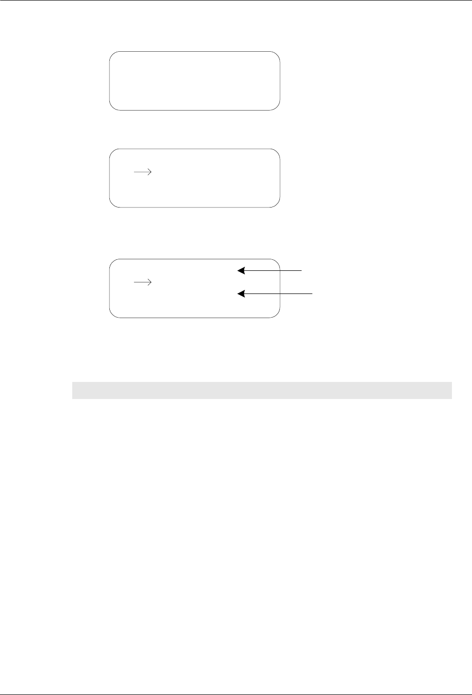
Wait to view the Reading Listen Data screen.
Wait to view the Listening List.
The Listening List and Port List have two main parts. The first line consists
of the column headings. The remaining three lines are actual list items.
The column headings, their meanings, and the values for the list items are shown in
the following table.
Table 2.4
Listening list & port list column headings and list item values
Column Heading Description Values
IED IED serial number Any valid 10 digit IED serial
number, or the term “Empty”
on the Port List only to denote
ports with no IED assignment.
xx/xx1List Item Indicator - Indicates
the number of the currently
selected IED out of the total
number of IEDs in the list
Ex: 32 IEDs total, cursor
highlighting IED #14,
“14/32”.
P Port/Installation Indicator 1-7 = Port on the current
EMTR-3 on which the IED is
installed.
I = IED marked installed in
HHTR-3 records, but not
installed on current EMTR-3.
<blank> = if neither of above
conditions are met.
Manage Listen Mode
EMTR: ssssssssss
Reading Listen Data
Please Wait...
IED xx/xx P SR Cnt
ssssssssss X GT ccc
ssssssssss X GT ccc
ssssssssss X GT ccc
IED xx/xx P SR Cnt
ssssssssss X GT ccc
ssssssssss X GT ccc
ssssssssss X GT ccc
List Items
Column Headings
DRAFT

TWACS®-ORION® for UMT Products User Guide 25
Chapter 2 • Functional Description
The Listening List holds up to 39 lines of IED information. Since only three
IEDs fit on the screen at any time, the Listening List may contain more list
items than can fit on the display. Consequently the lists are scrollable.
6. When the list first displays, the cursor highlights the first item on the list.
Press the down arrow key to move the cursor through the list.
N
OTE
When you reach the third list item, you can push the down arrrow again to
view any items below it, but the cursor stays at the bottom of the display
while the entire display shifts down.
Listen List Installation Setup
The installation process begins when you press the Enter key on a non-installed
IED in the Listening List. The Port Number menu screen gathers the desired port
number for installation. If that port number is already occupied by another IED, the
IED status is gathered. If the port number is not already occupied, you will be
promped to select a service type.
Use the following procedure to install an IED using Manage Listen Mode.
1. Follow the steps in Manage Listen Mode on page 23 to view the Listening
List.
S Service Type Indicator W = Water
G = Gas
P = Propane
O = Other
<blank> = if unknown or port
is empty.
R Remote Type Indicator O = Orion (only remote type
currently supported)
<blank> = if unknown or port
is empty.
Cnt2RF Counts Up to three digits of RF
counts.
1 xx/xx is not an actual column heading, however it is presented here since it is
included on the column heading line.
2 There is no RF Counts field for the Port List.
Table 2.4
Listening list & port list column headings and list item values
Column Heading Description Values
IED xx/xx P SR Cnt
ssssssssss X GT ccc
ssssssssss X GT ccc
ssssssssss X GT ccc
DRAFT

26 TWACS®-ORION® for UMT Products User Guide
EMTR3 Menu
2. To begin installation, press Enter on an IED where the Port column is blank
or where the Port column displays an “I”. A blank Port column means the
IED has not been installed. An “I” in the Port column means the HHTR-3
has a record indicating it has already installed that IED on another EMTR-3.
3. Enter a port number using the keypad, and then press Enter to accept.
aIn the event the Port you’ve chosen is already occupied, you’ll see
the Port In Use Warning.
bPress ESC to return to the Port Number screen or press Enter to
overwrite the port assignment and view the Service Type menu.
4. Use the navigation keys to select the correct Service Type, and press the
Enter key to view the Install screen.
EMTR: ssssssssss
IED: ssssssssss
Enter Port Number_
Enter to Accept
Warn: Port In Use by
IED: ssssssssss
Continue Install?
ESC: NO, Enter: Yes
IED: ssssssssss
Enter Service Type
Water
Propane
Nat Gas
Other
Installing
IED: ssssssssss
Please Wait...
DRAFT

TWACS®-ORION® for UMT Products User Guide 27
Chapter 2 • Functional Description
Manage Port List
Use the following procedures to view the Port List using Manage Port List.
1. From the EMTR3 menu use the Up or Down navigation keys to select
Manage IEDs.
2. Press Enter to view the Select EMTR screen.
3. Enter a serial number using the keypad.
4. Press Enter to accept the serial number and view the Manage IED Menu.
5. Use the Up or Down Navigation keys to select Manage Port List, and press
Enter to view the Reading Port List screen.
Wait to view the Port List.
The Port List holds 7 lines of IED information. Since only three IEDs fit on
the screen at any time (one heading line and three list items) the Port List
may contain more list items than can fit on the display. Consequently the
lists are scrollable.
EMTR3 Menu
RCE Change Out
EMTR-3 Status
Manage IEDs
Select EMTR
Enter Serial Number
EMTR S/N________
Enter to Accept
Manage IED Menu
Manage Port List
Select:
Manage Listen Mode
Manage Port List
EMTR: ssssssssss
Reading Port List
Please Wait...
IED xx/xx P SR
ssssssssss X GT
ssssssssss X GT
ssssssssss X GT
DRAFT

28 TWACS®-ORION® for UMT Products User Guide
EMTR3 Menu
6. When the list first displays, the cursor highlights the first item on the list.
Press the down arrow key to move the cursor through the list. For more
information, see Listening list & port list column headings and list item
values on page 24.
N
OTE
When you reach the third list item, you can push the down arrrow again to
view any items below it, but the cursor stays at the bottom of the display
while the entire display shifts down.
Port List Installation Setup
When you press the Enter key on an empty port (no IED serial number for the
selected port) in the Port List, the installation process begins. The Select IED S/N
screen allows you to manually enter the desired IED serial number for installation.
If that serial number is already located on another port, the Duplicate Detected
Error screen displays. If the serial number is not already located on another port,
you will be promped to select a service type.
N
OTE
When entering an ORION gas or water IED serial number for installation, if the
serial number is less than than 79,999,999, drop the first digit, “7”, and enter
the seven remaining digits. For all ORION gas and water IEDS with serial
numbers equal to or greater than 80,000,000, enter all digits of the IED, which
will be from 8 to 10 digits.
Use the following procedure to install an IED using Manage Port List.
1. Follow the steps in Manage Port List on page 27 to view the Port List.
2. Press Enter on an empty port to view the Select IED S/N screen.
IED xx/xx P SR
Empty X
Empty X
Empty X
EMTR: ssssssssss
Enter Serial Number
IED S/N__________
Enter to Accept
DRAFT

TWACS®-ORION® for UMT Products User Guide 29
Chapter 2 • Functional Description
3. Enter an IED serial number using the keypad, and then press Enter to accept
and view the Service Type menu.
aIn the event the serial number you’ve entered is already located on
another port, you’ll see the Duplicate Detected Error screen.
Press any key to return to the Select IED S/N screen.
4. Use the navigational keys to select the correct Service Type and press the
Enter key to view the Install screen.
Installation Results
Whether you use the Manage Listen Mode or Manage Port List method of
installing an IED into an EMTR-3 port, there are only three possible results:
Success, Failure, or Unknown.
Once the installation is complete (success, failure, or unknown) you return to either
a Listening List or a Port List, which depends on the original list (Listening or Port)
and the outcome of the installation.
Successful Installation
Use the following procedure to navigate through the screens of a successful
installation.
1. From the Install screen wait to view the Install Successful screen.
IED: ssssssssss
Enter Service Type
Water
Propane
Nat Gas
Other
Already Installed
On port X!
Press Any Key
Installing
IED: ssssssssss
Please Wait...
Install Successful!
IED: ssssssssss
assigned to port X.
Press Any Key
DRAFT

30 TWACS®-ORION® for UMT Products User Guide
EMTR3 Menu
2. Press any key to view the IED Status screen.
3. Wait approximately 12 seconds to view the Engineering Data 1 screen.
4. Press any key to return to the originating list (either Manage Listen Mode or
Manage Port List) updated with the new IED.
Unknown Installation
Use the following procedure to navigate through the screens of an unknown
installation.
1. From the Install screen wait to view the Install Unknown screen.
2. Press any key to view the Reading Port List screen.
3. Wait approximately 12 seconds.
aIf the install is successful you will see the following screen:
IED Status
EMTR: ssssssssss
IED: ssssssssss
Reading IED Data...
IED Status
Reading: xxxxxxxxxx
LeakDet: X Tamper: X
Press Any Key
Install Unknown
Verify Install
Press Any Key
Verify Install
EMTR: ssssssssss
Reading Port List
Please Wait...
Install Successful!
IED: ssssssssss
assigned to port X.
Press Any Key
DRAFT

TWACS®-ORION® for UMT Products User Guide 31
Chapter 2 • Functional Description
bIf the status of the installation remains unknown you will see the
following screen:
cIf the installation fails you will see the following screen:
4. Press any key to continue.
Failed Installation
An installation that fails outright will display the Install Failed screen immediately
after the Install screen.
Press any key to return to the originating list.
IED Removal
This section addresses successful, unknown, and failed IED removals.
1. From the EMTR3 menu use the Up or Down navigation keys to select
Manage IEDs.
2. Press Enter to view the Select EMTR screen.
Install Unknown
Unable to Resolve
Press Any Key
Error: # xxx
Install Failed
Error: # xxx
Install Failed
EMTR3 Menu
RCE Change Out
EMTR-3 Status
Manage IEDs
Select EMTR
Enter Serial Number
EMTR S/N________
Enter to Accept
DRAFT

32 TWACS®-ORION® for UMT Products User Guide
EMTR3 Menu
3. Enter a serial number using the keypad.
4. Press Enter to accept the serial number and view the Manage IED Menu.
5. Use the Up or Down Navigation keys to select Manage Listen Mode or
Manage Port List, and press Enter.
6. Wait to view the Listening List or the Port List.
N
OTE
If you begin in the Port List, the Cnt field will not be present.
7. From the Listening List or Port List press Backspace on an installed IED to
view the Verify Removal screen.
8. Press Esc to return to the originating list, or press Enter to view the
Removing screen.
Manage IED Menu
Manage Port List
Select:
Manage Listen Mode
IED xx/xx P SR Cnt
ssssssssss X GT ccc
ssssssssss X GT ccc
ssssssssss X GT ccc
IED xx/xx P SR Cnt
ssssssssss P GT ccc
Verify Removal
Esc: No, Enter: Yes
Removing
IED: ssssssssss
Please Wait...
DRAFT

TWACS®-ORION® for UMT Products User Guide 33
Chapter 2 • Functional Description
Successful Removal
Follow the steps detailed in IED Removal and use the following procedure to
navigate through the screens of a successful removal.
1. Wait to view the Removal Successful screen.
2. Press any key to return to the originating list (Listening List or Port List).
Unknown Removal
Follow the steps detailed in IED Removal and use the following procedure to
navigate through the screens of an unknown removal.
1. Wait to view the Removal Unknown screen.
2. Press any key to view the Reading Port List screen.
3. Wait to view the Removal Successful screen
-OR-
Wait to view the Unable to Resolve screen.
Removal Successful!
IED: ssssssssss
removed from EMTR.
Press Any Key
Removal Unknown
Verify Removal
Press Any Key
Verify Removal
EMTR: ssssssssss
Reading Port List
Please Wait...
Removal Successful!
IED: ssssssssss
removed from EMTR.
Press Any Key
Removal Unknown
Unable to Resolve
Press Any Key
DRAFT

34 TWACS®-ORION® for UMT Products User Guide
EMTR3 Menu
-OR-
Wait to view the Removal Failed screen.
4. Press any key to return to the originating list (Listening List or Port List).
Failed Removal
Follow the steps detailed in IED Removal and use the following procedure to
navigate through the screens of a failed removal.
1. Wait to view the Removal Failed screen.
2. Press any key to return to the originating list (Listening List or Port List).
Error: # xxx
Removal Failed
Error: # xxx
Removal Failed
DRAFT

TWACS®-ORION® for UMT Products User Guide 35
Chapter 2 • Functional Description
RCE Change Out
At some point an Electronic Metering Assembly (EMA), Electric Meter
Transceiver-3 (EMTR-3), or both may need replacement. Assuming that the old
EMTR-3 is still functional, the original port list can be downloaded to the HHTR-3
prior to removal of the old Remote Communication Equipments (RCE). After RCE
replacement, the stored port list can be uploaded to the new EMTR-3 and operation
may resume. This process can be carried out with the RCE Change Out menu
selection. This selection allows the user to confirm proper installation and test the
network.
Use the following procedures to navigate the RCE Change Out screens.
Extract Port List
1. From the EMTR3 Menu, use the Up or Down arrow keys to select RCE
Change Out.
2. Press the Enter key to enter the serial number of an EMTR whose Port List
is to be reused (preserved).
3. Press Enter to accept and view the RCE Change Out menu.
4. Use the Up or Down keys to select Extract Port List.
EMTR3 Menu
Manage IEDs
EMTR-3 Status
RCE Change Out
Select EMTR
Enter Serial Number
EMTR S/N________
Enter to Accept
RCE Change Out
Install Port List
Select:
Extract Port List
DRAFT

36 TWACS®-ORION® for UMT Products User Guide
EMTR3 Menu
5. Press the Enter key to view the Extract Port List screen.
aIf the extraction fails you will see the following screen:
Press any key to return to the RCE Change Out screen.
bIf the extraction is successful you will see the following screen:
6. Press any key to return to the EMTR3 menu.
N
OTE
The extracted Port List will overwrite any previously extracted EMTR Port List
stored on the HHTR-3.
Extracting from
EMTR: ssssssssss
Reading Port List
Please Wait...
Error: # xxx
Extract Failed
Port List from…
EMTR: ssssssssss
Stored in memory.
Press Any Key
DRAFT

TWACS®-ORION® for UMT Products User Guide 37
Chapter 2 • Functional Description
Install Port List
1. From the EMTR3 Menu, use the Up or Down navigation keys to select RCE
Change Out.
2. Press the Enter key to enter the serial number of the EMTR onto which the
previously extracted Port List is to be installed.
3. Press the Enter key to accept and view the RCE Change Out menu.
4. Use the Up or Down keys to select Install Port List.
5. Press the Enter key.
aIf the Port List does not exist you will see the following screen:
Press any key to return to the RCE Change Out menu.
bIf the Port List does exist you will see the following screen:
EMTR3 Menu
Manage IEDs
EMTR-3 Status
RCE Change Out
Select EMTR
Enter Serial Number
EMTR S/N________
Enter to Accept
RCE Change Out
Extract Port List
Select:
Install Port List
Port List
Does Not Exist
Press Any Key
Port List to
install is from…
EMTR: ssssssssss
Enter to Accept
DRAFT

38 TWACS®-ORION® for UMT Products User Guide
EMTR3 Menu
6. Press Enter to view the Install Port List screen.
aIf the installation is successful you will see the following screen:
Press any key to return to the EMTR3 menu. The extracted list has been
cleared from the HHTR.
bIf the installation is not successful you will see the following
screen:
Press any key to return to the RCE Change Out menu.
Installing to
EMTR: ssssssssss
Writing Port List
Please Wait...
Port List to…
EMTR: ssssssssss
Install Successful!
Press Any Key
Error: # xxx
Install Failed
DRAFT

TWACS®-ORION® for UMT Products User Guide 39
Chapter 2 • Functional Description
EMTR-3 Status
The HHTR-3 has the capability to check the status of the EMTR-3 via an RF link.
The hardware version and firmware version information can be then be displayed.
Use the following procedures to navigate the EMTR-3 Status screens.
1. From the EMTR3 menu use the Up or Down navigation keys to select
EMTR-3 Status.
2. Press the Enter key to select an EMTR3.
3. Press Enter to view the Reading Status window.
Wait to see the status results.
4. Press any key to return to the EMTR3 menu.
EMTR3 Menu
Manage IEDs
RCE Change Out
EMTR-3 Status
Select EMTR
Enter Serial Number
EMTR S/N________
Enter to Accept
EMTR3 Status
EMTR: ssssssssss
Reading Status
Please Wait...
EMTR3 Status
HWR Gen/Rev: aaa/bbb
FWR Gen/Rev: ccc/ddd
Press Any Key
DRAFT

40 TWACS®-ORION® for UMT Products User Guide
PC Upload Menu
PC Upload Menu
The HHTR-3 maintains a database of the actions performed by the HHTR-3 for
every installaton, removal, and replacement of an Intelligent End Device (IED). It
also records any IEDs detected by an EMTR-3 during a designated listening mode.
All these records are maintained in an internal database. The HHTR-3 informs the
user when this database becomes full and allows the user to upload the existing
records prior to overwriting them.
The HHTR-3 has the capability to upload the database to a personal computer (PC)
that has the HHTR-PC application running on it. In addition to having the
HHTR-PC application installed on the destination PC, the upload process requires
the HHTR-3 to be connected to the PC via a special RS-232 serial data cable. For
more information on the HHTR-PC application see the HHTR-PC Application
Help.
To use the PC Upload feature of the HHTR-3, the HHTR-3 must be connected to a
PC with the HHTR-PC application installed on it. The following procedure
explains how to navigate the PC Upload screens.
1. From the Main Menu of the HHTR-3, use the navigation keys to place the
cursor to the left of PC Upload.
2. Press the Enter key to view the PC Upload screen.
N
OTE
It is possible for this screen to time out. If this happens, press Enter to return
to the Main Menu, select PC Upload, and press Enter to start the PC Upload
again.
3. Start the HHTR-PC application if it isn’t running on the PC.
Main Menu
EMTR-3
TWACS
HHTR Config
Serial Com
PC Upload
PC Upload
Waiting for PC to
initiate upload.
Please wait...
DRAFT
TWACS®-ORION® for UMT Products User Guide 41
Chapter 2 • Functional Description
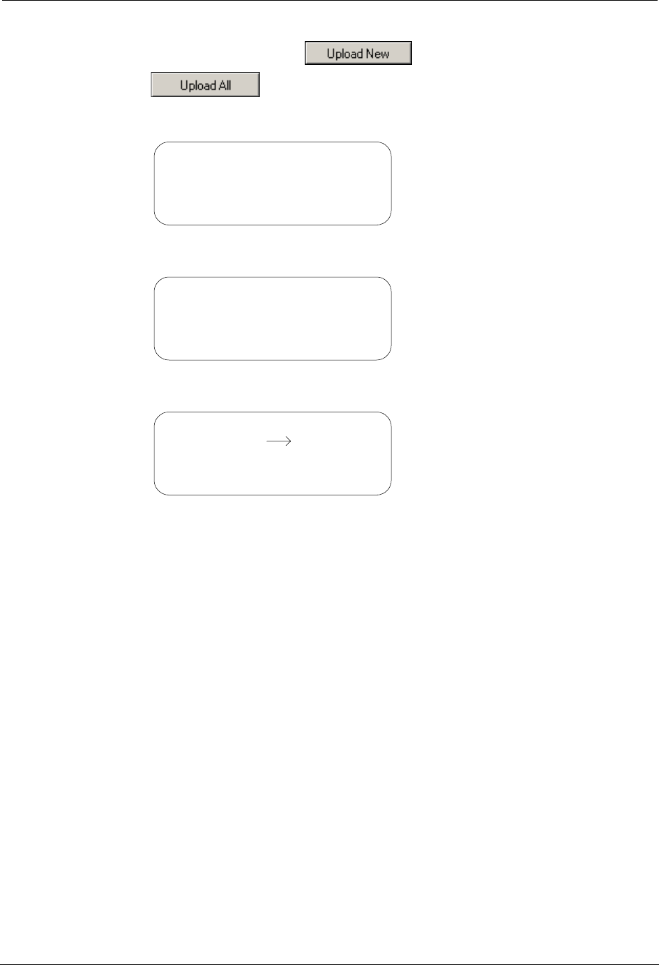
4. Click the Upload New button or the Upload All
button on the HHTR-PC application window.
Wait to view the Uploading Database screen on the HHTR-3 display.
Wait to view the Upload Complete screen.
5. Press any key to return to the Main Menu of the HHTR-3.
PC Upload
Uploading Database
Please wait...
PC Upload
Upload Complete
Press Any Key
Main Menu
EMTR-3
TWACS
HHTR Config
Serial Com
PC Upload
DRAFT

42 TWACS®-ORION® for UMT Products User Guide
HHTR Config Menu
HHTR Config Menu
The following procedures explain how to navigate the Setup, Power, Status, and
Diags screens associated with the HHTR Config menu.
Setup
1. From the Main Menu use the navigation keys to select HHTR Config.
2. Press the Enter key to view the HHTR Menu. The default selection is
Setup.
Audio
3. Press the Enter key to view the Setup selection options. The default
selection is Audio.
4. Press the Enter key to view the Keypad Beep menu.
Main Menu
EMTR-3
TWACS
PC Upload
Serial Com
HHTR Config
HHTR Menu
Select:
Status
Power
Diags
Setup
HHTR Menu
RF RMT
I/O Status
Com Logic
RF Time
Audio
HHTR Menu
Keypad Beep On/Off
ESC: No, Enter: Yes
DRAFT

TWACS®-ORION® for UMT Products User Guide 43
Chapter 2 • Functional Description
5. Press the Esc key to turn off the beep when keys are pressed, or press the
Enter key to turn the beep on when keys are pressed. Pressing either the Esc
key or the Enter key returns you to the Setup selection screen.
I/O Status
6. Use the navigation keys to select I/O Status.
7. Press Enter to view the I/O Status screen.
8. Press the Esc key or the Enter key to return to the Setup selection screen.
RF RMT
9. Use the navigation keys to select RF RMT.
10. Press Enter to view the RF Remote screen.
11. Press Esc to return to the Setup selection screen.
HHTR Menu
RF RMT
I/O Status
Com Logic
RF Time
Audio
HHTR Menu
O/Ps: H,H I/Ps: 1,1
AOUT: 02.47V
A1: 03.5V, A2: 03.5V
HHTR Menu
RF RMT Com Logic
RF Time
Audio I/O Status
HHTR Menu
RF Remote: 1200:8N1
Esc - Abort
HHTR Menu
Com Logic
RF Time
Audio I/O Status
RF RMT
DRAFT

44 TWACS®-ORION® for UMT Products User Guide
HHTR Config Menu
Com Logic
12. Use the navigation keys to select Com Logic.
13. Press Enter to view the Com Logic screen.
14. Press the Enter key to invert logic or press the Esc key to return to the
previous screen. Pressing either Enter or Esc returns you to the Setup
selection screen.
RF Time
15. Use the navigation keys to select RF Time.
16. Press Enter to view the RF Time screen.
17. Press Enter or Esc to return to the Setup selection screen.
18. Press Esc to return to the HHTR Menu.
HHTR Menu
Invert Logic RS232?
ESC: No, Enter: Yes
HHTR Menu
RF Time
Audio I/O Status
RF RMT Com Logic
HHTR Menu
RF Time Out After
Waiting: 035sec
HHTR Menu
Audio I/O Status
RF RMT Com Logic
RF Time
HHTR Menu
Select:
Status
Power
Diags
Setup
DRAFT

TWACS®-ORION® for UMT Products User Guide 45
Chapter 2 • Functional Description
Power
1. From the Main Menu use the navigation keys to select HHTR Config.
2. Press the Enter key to view the HHTR Menu. The default selection is Setup.
3. Use the navigation keys to select Power.
Power Off Time
4. Press Enter to view the HHTR Menu. The default selection is Power Off
Time.
5. Press Enter to view how long the HHTR-3 unit must remain idle before it
turns itself off.
The default value is 15 minutes. Increase the time by pressing the key,
or decrease the time by pressing the key.
6. Press Enter or Esc to return to the HHTR Menu.
Main Menu
EMTR-3
TWACS
PC Upload
Serial Com
HHTR Config
HHTR Menu
Select:
Status
Power
Diags
Setup
HHTR Menu
LCD Backlight Time
Battery Status
Power Off Time
HHTR Menu
Power off when idle
after: 015min
8
0
DRAFT

46 TWACS®-ORION® for UMT Products User Guide
HHTR Config Menu
LCD Backlight Time
7. Use the navigation keys to select LCD Backlight Time.
8. Press Enter to view the screen indicating how long the backlight on the
HHTR-3 display remains on after pressing a button.
The default value is zero. Increase the time by pressing the key, or
decrease the time by pressing the key.
9. Press Enter or Esc to return to the HHTR Menu.
Battery Status
10. Use the navigation keys to select Battery Status.
11. Press Enter to view the Battery Status screen.
12. Press Enter or Esc to return to the HHTR Menu.
HHTR Menu
Battery Status
Power Off Time
LCD Backlight Time
HHTR Menu
LCD backlight stays
on for: 0sec
8
0
HHTR Menu
LCD Backlight Time
Power Off Time
Battery Status
HHTR Menu
Charging: No
Battery: 7.84V
Time On Bat 00:45:27
HHTR Menu
LCD Backlight Time
Battery Status
Power Off Time
DRAFT

TWACS®-ORION® for UMT Products User Guide 47
Chapter 2 • Functional Description
13. Press Esc to return to the main HHTR Menu.
Status
1. From the Main Menu use the navigation keys to select HHTR Config.
2. Press the Enter key to view the HHTR Menu. The default selection is Setup.
3. Use the navigation keys to select Status.
4. Press Enter to view the Status screen.
5. Press Enter or Esc to return to the HHTR Menu.
HHTR Menu
Select:
Status
Power
Diags
Setup
Main Menu
EMTR-3
TWACS
PC Upload
Serial Com
HHTR Config
HHTR Menu
Select:
Status
Power
Diags
Setup
HHTR Menu
HHTR S/N: 5372281
HHTR Rev: 3.0
HEMTR Rev: 00002.10
HHTR Menu
Select:
Status
Power
Diags
Setup
DRAFT

48 TWACS®-ORION® for UMT Products User Guide
HHTR Config Menu
Diags
1. From the Main Menu use the navigation keys to select HHTR Config.
2. Press the Enter key to view the HHTR Menu. The default selection is
Setup.
3. Use the navigation keys to select Diags.
4. Press Enter to view the Diags screen. The default selection is Test Memory.
Test Memory
5. Press Enter to test PGM memory and view the screen below.
Once the PGM Memory test finishes, the I2C Memory test begins, and you
will see the screen below.
Main Menu
EMTR-3
TWACS
PC Upload
Serial Com
HHTR Config
HHTR Menu
Select:
Status
Power
Diags
Setup
HHTR Menu
Test Keypad/LCD
Test I/O & RS232
Test Memory
HHTR Menu
Testing PGM Memory
Please Wait...
HHTR Menu
Testing I2C Memory
0KB/32KB
Please Wait...
DRAFT

TWACS®-ORION® for UMT Products User Guide 49
Chapter 2 • Functional Description
Once the I2C Memory test finishes the HHTR-3 displays the results.
6. Press Enter or Esc to return to the Diags screen.
Test Keypad/LCD
7. Use the navigation keys to select Test Keypad/LCD.
8. Press Enter to view the Testing LCD screen.
The screen briefly flashes before displaying the Keypad Test screen.
9. Press Esc to return to the Diags screen.
HHTR Menu
PGM Memory: Pass
I2C Memory: Pass
HHTR Menu
Test I/O & RS232
Test Memory
Test Keypad/LCD
HHTR Menu
Testing LCD
HHTR Menu
Keypad Test
Key Pressed: None
Esc - Abort
DRAFT

50 TWACS®-ORION® for UMT Products User Guide
HHTR Config Menu
Test I/O & RS232
10. Use the navigation keys to select Test I/O & RS232.
11. Press Enter to view the I/O Test Results screen.
12. Press Esc to return to the HHTR Menu.
HHTR Menu
Test Keypad/LCD
Test Memory
Test I/O & RS232
HHTR Menu
I/O Test: Pass
HHTR Menu
Select:
Status
Power
Diags
Setup
DRAFT

TWACS®-ORION® for UMT Products User Guide 51
Chapter 2 • Functional Description
TWACS Menu
The following procedures explain how to navigate the HRTS and TWACS Modem
screens associated with the TWACS menu.
HRTS
1. From the Main Menu use the navigation keys to select TWACS.
2. Press the Enter key to view the TWACS screen. The default selection is
HRTS.
3. Press Enter to view the Collecting Data screen.
After a brief display the Select Meter Type screen replaces the Collecting
Data screen. IM2/MIT is the default selection.
Main Menu
HHTR Config
Serial Com
PC UploadEMTR-3
TWACS
TWACS
TWACS Modem
HRTS
HRTS
Please Wait…
Collecting Data
HRTS
Select Meter Type:
IMT3
IMT2/MIT
DRAFT

52 TWACS®-ORION® for UMT Products User Guide
TWACS Menu
4. Press Enter to select IMT2/MIT or use the navigational keys to select
IMT3.
5. Press the Esc key to return to the TWACS screen.
TWACS Modem
1. From the Main Menu use the navigation keys to select TWACS.
2. Press the Enter key to view the TWACS screen. The default selection is
HRTS. Use the Down (0) key to select TWACS Modem.
3. Press Enter to view the following screen.
4. Press the Esc key to return to the TWACS screen.
HRTS
Can Not Connect…
Esc – Abort
Enter - Retry
TWACS
TWACS Modem
HRTS
Main Menu
HHTR Config
Serial Com
PC UploadEMTR-3
TWACS
TWACS
HRTS
TWACS Modem
This Feature is not
support yet...
Press Esc...
TWACS
TWACS Modem
HRTS
DRAFT

TWACS®-ORION® for UMT Products User Guide 53
Chapter 2 • Functional Description
Serial Com Menu
The following procedures explain how to navigate the Baud Rate, Display, and
Buffer screens associated with the Serial Com menu.
1. From the Main Menu use the navigational keys to select Serial Com.
2. Press the Enter key to view the Baud Rate Logic screen.
N
OTE
You can select 2400, 4800, or 9600 by using the navigation keys.
3. Press Enter again to view the Baud Rate RS232 screen.
4. Press Enter again to view the Display On/Off screen.
5. Press Enter again to view the Display ASCII screen.
Main Menu
HHTR Config
PC UploadEMTR-3
TWACS Serial Com
Serial Com
Baud Rate Logic
4800
2400
9600
1200
Serial Com
Baud Rate RS232
4800 9600
1200 2400
Serial Com
Display On/Off
Off
On
Serial Com
Display ASCII?
Off
On
DRAFT

54 TWACS®-ORION® for UMT Products User Guide
Serial Com Menu
6. Press Enter once more to view the Buffer screen, which shows how full the
left and right buffers are.
7. Press the Esc key to return to the Main Menu.
Serial Com:
BufL: 0% BufR: 0%
L:
R:
Main Menu
HHTR Config
PC UploadEMTR-3
TWACS Serial Com
DRAFT

TWACS®-ORION® for UMT Products User Guide 55
CHAPTER
3
T
ROUBLESHOOTING
This chapter explains how to test and manage typical TWACS® ORION® system
problems. It is useful for installers and meter shop personnel. Foremost, it provides
diagnostic information through the TNS and TWACS NG systems which give you
a better assessment of problem conditions before field personnel are dispatched.
There are three essential sources of diagnostic information:
• The Intelligent End Device (IED) status, including leak detection, tamper
detection, and port assignment.
• Among the four bytes of total consumption readings are specific bits of data
for port-specific status information.
• The EMTR-3 diagnostic indicators.
Performing Remote Analysis (TNS)
Complete the following steps to determine if a field visit is required for an
unresponsive meter. You can end the procedure at any step and correct the problem
when a cause of failure is determined.
1. Check the AMRCOMMFAIL table for TWACS serial numbers that have
excessive AMR Communication Failure counts. This enables you to
identify meters that are consistently failing AMR.
If the meter fail count in the AMRCOMMFAIL table is equal to or greater
than the MaxFailCnt in the TNSDEFAULTS table, the Quality Code (QC)
will be set to RO (Retry Override). When the quality code is RO, the meter
unit map will have changed in the AMRCMDLST2WAY table. The meter
will be attempted the first time, but will not be issued subsequent retries and
must be read manually.
2. Determine if any error messages have occurred during AMR by checking
the SCE Notification log for any associated hardware issues for the meters
that are not communicating.
N
OTE
The Notification log contains important information about the status of
equipment and is automatically updated by TNS and the SCE. For detailed
information about the Notification log and error messages, see the
Notification Log section of the SCE Logs chapter in the TNS Operational
Process Guide (Y10352TM) and the Notification Log section in the SCE
Maintenance chapter of the TNS End User Guide (Y10285TM).
DRAFT

56 TWACS®-ORION® for UMT Products User Guide
Performing Remote Analysis (TNS)
3. Check for TNS errors that may have occurred because of commands
time-out, or any software related issues in TNS that may have prevented
AMR commands processing.
For more information on time-out issues, see the Encode Command
Parameters section in the TNS System Maintenance chapter of the TNS End
User Guide.
4. Perform an On-Request AMR command to determine if the unit
communicates. (This command communicates to the unit by serial number
to eliminate a two-way addressing issue.)
For more information about On-Request meter reads, refer to the
appropriate sections in the TNS End User Guide and the TNS Operational
Process Guide.
A site visit is not required, and you may stop this procedure if the meter
communicates. If the meter communicates, check two-way addressing.
(For more information on two-way addressing, see the Function-Group
Addressing chapter of the TNS Operational Process Guide and the
Two-Way Addressing section in the TNS Generic Applications chapter of
the TNS End User Guide.)
5. Check for other TWACS meters that are reading on the same distribution
transformer, or a nearby meter to narrow the communication problem area.
6. Check the Customer Information System for a disconnected status that may
not have updated in the TNS database. If the meter was disconnected, no
action in TNS is required, but you may want to change the cycle number.
The TNS Operator must have some process for dealing with a meter that no
longer provides a read. The TNS Operator might consider setting up a
special cycle (e.g. cycle 99) for disconnects and continue reading the
meters. Having the disconnected meters in a special cycle allows the TNS
Operator to isolate meters to scan for usage. If a Customer Service
Representative re-activates the service and the notification fails to reach the
TNS Operator, or if a customer tampers with the meter and reconnects the
service, the TNS Operator can quickly identify a successful read in a group
of meters where reads should normally fail. Using this configuration, the
TNS Operator can quickly investigate the reason for the successful read of a
supposedly disconnected meter.
7. Check for switching events which may have occurred in the system that
possibly changed the communication path of the meter. (A communication
path may have changed due to a physical move or a temporary switch to a
different substation, phase, or other path component.) If the communication
path has changed, you can use Pathmaps to update the TNS database.
For more information on communication paths, see the Adding Meters
Interactively section in the Searching Meters chapter of the TNS
Operational Process Guide. For more information on Pathmaps, see the
Alternate Pathmaps Search chapter in the TNS End User Guide and the
Building and Searching Alternate Paths chapter in the TNS Operational
Process Guide.
DRAFT
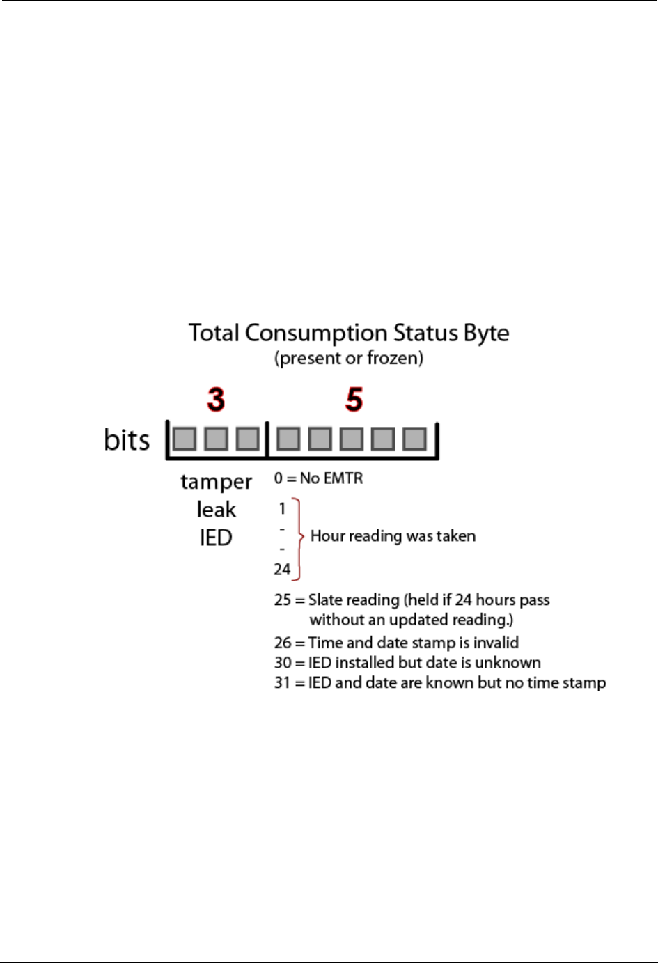
TWACS®-ORION® for UMT Products User Guide 57
Chapter 3 • Troubleshooting
8. Check the Alternate Substation tables for up-to-date information on
Alternate Substations that can feed the primary sub.
For more information on Alternate Substation tables, see the Adding
Alternate Substation Information section in the SCE Maintenance chapter
of the TNS End User Guide. Also see the Alternate Substation Mapping and
Creating and Using Alternate Path Tables sections in the Building and
Searching Alternate Paths chapter of the TNS Operational Process Guide.
Port Specific Status Information
There is one byte within the Total Consumption reading (present or frozen) which
contains data that may be invaluable for diagnosing and troubleshooting issues
prior to rolling a truck.
Total Consumption (TC) registers (Present and Frozen Daily) on the EMTR-3
contain a three byte TC value and a one byte status. In the status, the Hour of
Reading and Configuration field is used to establish a desired level of validity for
the TC reading. This five bit field also serves as a quick alternate method for time
stamping the data.
The Hour of Reading and Configuration field provides a number of different levels
of information. There are four error conditions the field can report and if none of
those errors are present, the field is an indication of the quality of the TC reading.
DRAFT

58 TWACS®-ORION® for UMT Products User Guide
Performing Remote Analysis (TNS)
The CCE has the capability to decide the quality of a TC reading based on the
Hour of Reading and Configuration field in the status byte of the Total
Consumption registers.
If the Hour of Reading and Configuration field is equal to zero, the CCE marks the
TC data as suspect. If this is the case, there is no EMTR-3 present.
If the Hour of Reading and Configuration field is equal to twenty five, the CCE
marks the quality of TC data appropriately.
If this is the case, the time and date stamp for the data is more than twenty four
hours old.
When the Hour of Reading and Configuration is equal to twenty five or twenty
six, the CCE uses the current date and time to mark when the TC data was received
at the master station.
If the Hour of Reading and Configuration field is equal to twenty six, the CCE
marks the quality of TC data appropriately based on the utility configured quality
rules. If this is the case, the time and date stamp for the data is invalid.
If the Hour of Reading and Configuration field is equal to thirty, the CCE marks
the TC data as suspect. If this is the case, an IED is installed but no data has been
received yet.
If the Hour of Reading and Configuration field is equal to thirty one, the CCE
marks the TC data as suspect. If this is the case, there is no IED installed on this
port.
IED Configuration Data Files
TNS has the capability to produce IED Configuration Data files, as defined in this
section, for export to other applications. The IED Configuration Data export file is
composed of a number of records.
Each data record in the IED Configuration Data export file contains the data fields
listed in Table 2.
Each data record in the IED Configuration Data export file always populates the
following fields: Meter Number, Serial Number, Serial Port and Device Type.
Any field in an IED Configuration Data record that is not populated is left blank.
The IED Configuration Data export file is a delimited file constructed by
sequentially delimited data records. The comma and vertical pipe characters are
valid delimiters for an IED Configuration Data export file.
Each data record in the IED Configuration Data export file is separated by a
line-feed and carriage return character (in that order).
DRAFT

TWACS®-ORION® for UMT Products User Guide 59
Chapter 3 • Troubleshooting
Field Name Field Description Valid Input
Meter Number The meter number assigned by
the utility. IED Serial Number.
[1 – 4294967295]
Serial Number TWACS Serial Number. [1 – 4294967295]
Serial Port Port to which the IED is
associated.
[1 - 7]
Premises ID Number Premises ID assigned by utility,
for the Port of interest (1-7).
String (20)
Port District Number District Number Assigned by
Utility.
[0 – 999999]
Port District Location Location Identifier of the meter
assigned by the utility.
String(5)
Active Flag A flag to identify that the device
is active.
Y, N
Device Type IED Service Type
0 = Electric
1 = Water
2 = Gas
3 = Propane
4 = Other
0, 1, 2, 3, 4
Port User 1 A field assigned by the utility or
DCSI for grouping purposes. May
be blank.
String(16)
Port User 2 A field assigned by the utility or
DCSI for grouping purposes. May
be blank.
String(16)
Customer Account Number Customer account assigned by the
utility.
String(20)
Rate Class The rate class assigned by the
utility.
String(8)
Meter Type The meter type to associate with
the conversion table. The system
uses a default if left blank.
String(10)
Route ID The Route ID associated with the
meter assigned by the utility.
String(8)
Cycle Number The cycle number for the AMR
assigned by the utility.
[0 – 999]
Meter User 1 A field assigned by the utility or
DCSI for grouping purposes. May
be blank.
String(16)
Meter User 2 A field assigned by the utility or
DCSI for grouping purposes. May
be blank.
String(16)
DRAFT

60 TWACS®-ORION® for UMT Products User Guide
Performing Remote Analysis (TWACS NG)
Performing Remote Analysis (TWACS NG)
Complete the following steps to determine if a field visit is required for an
unresponsive meter. You can end the procedure at any step and correct the problem
when a cause of failure is determined.
1. If communication fails to the transponder, check the path and search state of
the transponder. You may do this by going to System Monitoring > Edit
Path > Search States.
2. Type in the serial number of the transponder and click Lookup.
If the transponder is currently in the New, Lost or Tentative path state, the
the TWACS NG will need to search the transponder. The TWACS NG
Operator will need to be sure that it is in a search state of Ready. The search
batch job should automatically pick up the transponder for search when the
next job runs.
3. If the transponder is in a Good/Done state, the TWACS NG Operator may
issue a ping to the transponder. You may do this by going to System
Monitoring > Test Transponder screen.
4. Type in the serial number or Meter/End Device ID and click Ping.
If the ping is successful, communication to the transponder is successful
and has been verified. If the transponder is still not functioning as expected,
a field visit will most likely be necessary.
Meter Number The meter number assigned by
the utility. IED Serial Number.
[1 – 4294967295]
Serial Number TWACS Serial Number. [1 – 4294967295]
Serial Port Port to which the IED is
associated.
[1 - 7]
Premises ID Number Premises ID assigned by utility,
for the Port of interest (1-7).
String (20)
Port District Number District Number Assigned by
Utility.
[0 – 999999]
Port District Location Location Identifier of the meter
assigned by the utility.
String(5)
Active Flag A flag to identify that the device
is active.
Y, N
Device Type IED Service Type
0 = Electric
1 = Water
2 = Gas
3 = Propane
4 = Other
0, 1, 2, 3, 4
Field Name Field Description Valid Input
DRAFT

TWACS®-ORION® for UMT Products User Guide 61
Chapter 3 • Troubleshooting
5. The TWACS NG Operator may also want to check the notifications to
verify if any have been received for the transponder in question. For more
information regarding notifications, refer to the Notifications section of the
TWACS® Network Gateway Operational Process Guide.
6. If the previous steps determine that the meter has “Failed”, see Product
Returns on page 3 to return the meter.
N
OTE
For additional information regarding remote troubleshooting, contact DCSI
Customer Care (email care@twacs.com or call 1-800-892-9008) to speak with a
Technical Support Engineer.
EMTR-3 Diagnostic Indicators
The following table lists the error code number and error message text that the
HHTR displays when the specific error is encountered while communicating with
the EMTR-3.
Table 3.1
Error code description and solution
Error Description Solution
The following error codes are RF communication errors.
01 RF Error General error. Retry the command.
02 Service Not Supported Service is not supported. Retry the command.
04 Operation Not Possible RF error. Retry the command.
05 Inappropriate Action
Requested
RF error. Retry the command.
06 RF Device Busy RF error. Retry the command.
07 Data From Device Not
Ready
RF error. (Usually memory) Retry the command.
31 RF Device Sent NAK RF error Retry the command.
32 Can not acquire an RF Link RF error Retry the command.
33 Operation Timed Out Operation time expired without
success.
Retry the command.
The following error codes are internal HHTR-3 or user errors.
101 RFPIC sends a NAK The RFPIC isn't ready or doesn't
understand the command. The RF
PIC internal to the HHTR-3 has
failed.
Retry the command.
102 RFPIC is Busy! RFPIC is performing another
operation and is currently busy.
The RF PIC internal to the
HHTR-3 was in the middle of
another command.
Retry the command.
103 No response from RFPIC
on HHTR
The RFPIC isn't responding to the
UI. No Response from the RF
PIC. The RF PIC didn't respond
to the UI processor.
Retry the command.
DRAFT

62 TWACS®-ORION® for UMT Products User Guide
EMTR-3 Diagnostic Indicators
If you are unable to resolve a problem with the TWACS® ORION® system, return
the meter to your integrator or DCSI. See Product Returns on page 3 for
instructions.
Record Overwrite Warning
The Record Overwrite Warning displays when you attempt to install or delete an
IED, perform an RCE Change Out, or select Manage Listen Mode when there are
an insufficent number of database records available.
There are two Record Overwrite Warnings. The first Record Overwrite Warning
can be seen below.
Press any key to view the second Record Overwrite Warning.
Press ESC to return to the originating list, or press Enter to continue the operation
and overwrite the existing records.
104 RFPIC Sent Invalid
Response. . .
The RFPIC sent an invalid
response to the UI. The HHTR-3
UI processor didn't recognize the
response from the RF PIC.
Retry the command.
105 Operation Cancelled Indicates the Esc button was
pressed during an operation.
Continue to desired action.
221 Install Failed The HHTR was unable to install
the IED.
Retry the command
222 Removal Failed The HHTR was unable to remove
the IED.
Retry the command
223 Extract Failed The HHTR was unable to extract
the port list from EMTR.
Retry the command
230 PC Upload Incomplete The PC upload operation was
aborted by the operator or there
was a communication timeout.
Resolve any
communication errors.
Check cable. Ensure PC
application is functional.
Retry the command.
Error Description Solution
Warn: Database Full
Upload Data to PC
Press Any Key
Warn: Database Full
Continue Operations &
Overwrite Records?
ESC: No, Enter: Yes
DRAFT

TWACS®-ORION® for UMT Products User Guide 63
Chapter 3 • Troubleshooting
Field Troubleshooting
Distribution Control Systems, Inc. has developed various software and hardware
products for testing TWACS-enabled devices in the field and the meter shop. See
Meter Shop Test System on page 64 of this chapter for information regarding use of
this system.
The EMTR-3 has no field serviceable parts. It can only install, delete, or query
installed ORION transmitters.
When necessary, the HHTR can be used to -
• Install the Orion transmitter
N
OTE
The HHTR can not communicate with the Orion transmitter.
• Query the EMTR for a remote installed list
• Delete Orion from the EMTR installed list
• Check EMTR status (Hardware & Firmware version)
A remote list query by the HHTR gives port-specific information for each installed
Orion transmitter as follows:
• Serial Number & Service Type
• Acquisition Failures
• 24 Hr. Acq Log
• Orion Status
•Present Total Consumption (not current total consumption, but rather last
RF communication total consumption, usually < 1 hr. old)
•Leak Detect (tripped by water meter, will reset on its own, or can be
manually reset in the field; see the meter manufacturer documentation for
trip and reset conditions)
•Tamper Detect (must be field reset at water meter)
If there is a problem, the applicable error code is displayed.
DRAFT

64 TWACS®-ORION® for UMT Products User Guide
Meter Shop Test System
Meter Shop Test System
Use the Meter Shop Test System to test TWACS signaling, read select transponder
registers, zero select transponder registers, and perform various other transponder
functions on a TWACS-enabled FOCUS meter. For complete details on the Meter
Shop Test System, see the Meter Shop Test System Help (accessed by clicking the
Help button on the Meter Shop Test Tool main menu) or contact your Program
Manager or DCSI Customer Care at care@twacs.com or 1-800-892-9008.
Because of the various test equipment available for use with DCSI products and
the configuration requirements/options, the Meter Shop Test System Set-Up Guide
(Y10030TM) will guide you through initial equipment selection and setup for
meter/module testing.
If you are unable to resolve a problem with the TWACS®-ORION® System, return
the meter to your integrator or DCSI. See Product Returns on page 3 for
instructions.
DRAFT

TWACS®-ORION® for UMT Products User Guide 65
CHAPTER
4
S
PECIFICATIONS
This chapter contains electrical, environmental, and physical specifications for the
EMTR-3 and HHTR-3.
Electrical Specifications
The electrical specifications include:
• Electrical ratings
• Compliance Specifications
Electrical Ratings
The following table provides the electrical ratings for the EMTR-3.
Table 4.1
Electrical ratings
Parameter Rating
Voltage 6V<=V<=12V
Quiescent power 25mA approximate
Maximum input surge 100mA maximum
Internal fusing None
Grounding None
Electronics connection The EMTR-3 is connected to the
UMT-R-F MP or UMT-C-KV MP
transponder during meter/transponder
integration.
Electronics isolation Refer to the Universal Metering Transponder
for FOCUS Meter User Guide
(Y10574-TUM) or the Universal Metering
Transponder for kV2c Meter User Guide
(Y10577-TUM).
DRAFT

66 TWACS®-ORION® for UMT Products User Guide
Electrical Specifications
Compliance Specifications
N
OTE
ANSI C12.1-3001 is the referring standard for tests listed in tables 3.2, 3.3, and
3.4.
N
OTE
Per Measurement Canada, Specifications/Standards LMG-EG-07 & PS-E-09-E
are used to verify compliance with Canadian criteria.
Table 4.2
Compliance specifications
Device(s) Test Title Applicable Specification
HHTR-3
and
EMTR-3
EMI/RFI Emission
conducted/radiated
ANSI C12.1-3001 Test No. 27- “Radio
Frequency Conducted and Radiated Emissions”
per CFR 47 Part 15, Class A and B. (See also
ANSI C63.4)
HHTR-3
and
EMTR-3
EMI/RFI Susceptibility ANSI C12.1-3001 Test No. 26- “Effect of Radio
Frequency Interference”
EMTR-3 AC line surge ANSI C12.1-3001/IEEE C62.41-1991 Test No.
17- “Effect of High Voltage Line Surges”
EMTR-3 Electrical fast transient ANSI C12.1-3001 Test No. 25- “Electrical Fast
Transient/Burst” (Testing at 100 and 400 KHz is
required) IEC 801-4: 1988
EMTR-3 Surge withstand
capability FT and OSC
ANSI/IEEE C.37.90.1 - 2002
EMTR-3 High voltage isolation on
meter chassis
ANSI C12.1-3001 Test No. 15- “Insulation”
EMTR-3 Voltage interruption test ANSI C12.1-3001 Test No. 16- “Voltage
Interruption”
HHTR-3
and
EMTR-3
Effect of electrostatic
discharge
ANSI C12.1-3001 Test No. 28- “Effect of
Electric Discharge (ESD)”
EMTR-3 Effect of Variation of
Frequency
ANSI C12.1-3001. Test #6
EMTR-3 Effect of Variation of
Voltage on the Metering
Device
ANSI C12.1-3001. Test #5.
HHTR-3
and
EMTR-3
Occupied Bandwidth 200 kHz. The ORION equipment transmits at
100 kilobits/second. The HHTR transmits at
9600 bits per second, but uses a wider frequency
deviation so that the occupied bandwidth is still
in the 200 kHz range.
HHTR-3
and
EMTR-3
RF Output Power FCC 15.249 compliant. IC RSS-210 A2.9; 2005
compliant.
HHTR-3
and
EMTR-3
Design Frequency
Accuracy
+/- 50 parts per million.
DRAFT

TWACS®-ORION® for UMT Products User Guide 67
Chapter 4 • Specifications
Environmental Specifications
Physical Specifications
Table 4.3
Environmental specifications
Thermal
Effect of operating temperature Per ANSI C12.1-3001 Test No. 30
Humidity
Effect of relative humidity, both
operational and storage
Per ANSI C12.1-3001 Test No. 31
Table 4.4
Physical specifications
Parameter Specification
Size, weight, form factor
Integrated dimensions Meter-specific
Installation instructions Provided with shipping package. One per
TWACS-enabled meter carton.
Compliance Testing Specifications
Mechanical tests
• Mechanical Shock
• Mechanical Vibration
• Transportation Drop Test
• Transportation Vibration
Per relevant sections of ANSI C12.1 - 2001
described below:
• Test #32, per IEC 60068 part 2-37
• Test #34, per IEC 60068 part 2-6
• Test #33, per ISTA Test Procedure 1A
• Test #35, per ISTA Test Procedure 1A
Physical Tamper Protection
Meter seal Supported
Labeling Requirements and Serial
Number
DRAFT

68 TWACS®-ORION® for UMT Products User Guide
Physical Specifications
HHTR-3 Labeling per ANSI C12.10-1987 for:
• DCSI/customer name
• DCSI/customer logo
• TWACS serial number
• Barcode
Table 4.4
Physical specifications
Parameter Specification
DRAFT

TWACS®-ORION® for UMT Products User Guide 69
Chapter 4 • Specifications
Additional Regulatory Data
The following is a tabulation of regulatory data found elsewhere in this manual and
is required by the regulatory agencies of some countries.
Parameter Specification
Disclaimer noting that
operation of the device is
subject to conditions that the
device may not cause harmful
interference and device must
accept any interference
received.
Regulatory Data note, page 12.
Principles of device operation All of Chapter 2.
Block diagram Page 11.
Operating frequency Page 10, paragraph 2.
Channeling Page 11.
Mode of transmission Page 11.
Internal/External data source Page 11.
Type(s) of modulation Page 11.
Is a subcarrier used to modulate
carrier?
No, page 11.
Type of information transmitted Digital data, page 10, paragraph 2.
Occupied bandwidth 200 kHz, page 11.
RF output power FCC 15.249 compliant. IC RSS-210
A2.9; 2005 compliant. Page 66,
second-to-last item in table.
Carrier frequency stability +/- 50 ppm. Page 66, last item in table.
DRAFT

70 TWACS®-ORION® for UMT Products User Guide
Additional Regulatory Data
DRAFT

TWACS®-ORION® for UMT Products User Guide 71
AMR Automatic Meter Reading
ASCII American National Standard Code for Information Exchange
CCE Central Control Equipment
CFG Configuration
CIS Customer Information System
DCSI Distribution Control Systems, Inc.
EMTR Electric Meter Transceiver
FCC Federal Communication Commission
FSK Frequency Shift Keying
HHTR Hand Held Transceiver
HRTS Handheld Remote Test Set
IED Intelligent End Device
KWH Kilowatt Hours
MDM Meter Data Management System
NA Invalid Data
NS Register Not Supported
OK Successful Read
PA Power Amplifier
RCE Remote Communications Equipment
RF Radio Frequency
RI Reset In Progress
RL Register Length Invalid
RMTR Remote MeterTransceiver
RSSI Received Signal Strength Indicator
RTC Real-Time Clock
S/N Serial Number
TD Total Demand
TNS TWACS Net Server
TWACS Two-Way Automatic Communication System
WMS Work Management System
Acronyms
DRAFT

72 TWACS®-ORION® for UMT Products User Guide
Acronyms
DRAFT

TWACS®-ORION® for UMT Products User Guide 73
AMR
See Automatic Meter Reading.
Automatic Meter Reading (AMR)
Electronic accumulation and transport of meter data.
CCE
See Central Control Equipment.
CIS
See Customer Information System.
Central Control Equipment (CCE)
Computer and related components installed at the utility’s central office. These components
include the TWACS Net Server (TNS) and communication equipment connecting the TNS
system with Level 2 Substation Communications Equipment (SCE).
Customer Information System (CIS)
A utility central office application that maintains customer data. This customerily includes
account, premise, and contact information.
dial encoder
A device that encodes or converts the position of metering dials (normally used in water
meters) into an electrical signal for subsequent processing and transmission.
Electric Meter Transceiver (EMTR)
An electronic communication device that transmits and receives using RF transmission.
EMTR
See Electric Meter Transceiver.
Federal Communication Commission (FCC)
The Federal Communications Commission (FCC) is an independent United States
government agency, directly responsible to Congress, and is charged with regulating interstate
and international communications by radio, television, wire, satellite and cable. Among its
duties, the FCC is responsible for rating personal computers and other electronic equipment as
either Class A or Class B. The ratings indicate how much radiation a particular device emits.
Glossary
DRAFT

74 TWACS®-ORION® for UMT Products User Guide
Glossary
firmware
Programming code that is stored on a microchip within an electronic assembly that can not be
changed by the user and is accessible only with special equipment.
frequency shift keying
A data transmission control method that modulates, i.e. “shifts” between two radio
frequencies.
hand held transceiver (HHTR)
A control device used to set up, link, and establish communication between the EMTR and
RMTR components of the TWACS RF system.
IED
See Intelligent End Device.
industrial, science, and medical (ISM)
An unlicensed radio frequency band.
Intelligent End Device (IED)
A device incorporating one or more processors with the capability to recieve data from an
external source or to send data to an external source.
ISM
See Industrial, Science, and Medical.
MDM
See Meter Data Management System.
Meter Data Management System (MDM)
A system that manages meter reading data. Meter readings can be saved as needed for billing
and hisotrical analysis. The MDM would minimally manage configuration information for
meters and maintain measurement histories.
nonvolatile memory
A physical data storage area that maintains its content when the power is turned off.
pulser
An electronic or magnetic device that generates electric pulses in a quantity that is
proportional to the physical variable under measurement and which the pulses represent.
RCE
See Remote Communication Equipment.
DRAFT

TWACS®-ORION® for UMT Products User Guide 75
Glossary
received signal strength indicator (RSSI)
A value indicating the strength of the received radio frequency signal.
registers
Data storage locations on the transponder microprocessor that contain a variety of information
that is retrievable by the master station. The type of data in registers includes consumption and
demand data.
Remote Communication Equipment (RCE)
Devices, such as transponders, located at a consumer's premises that collect and transmit
register data through TWACS.
RSSI
See Received Signal Strength Indicator.
TNS
See TWACS Net Server.
transponders
Two-way field devices that can receive and send messages to and from the substation.
TWACS
See Two-Way Automatic Communication System.
WMS
See Work Management System.
Work Management System (WMS)
A utility central office application that manages the logistics of placing the necessary
personnel, tools, and parts at a given location at the same time to accomplish a given task. A
WMS may be able to supply the installer with an electronic copy of the list of sites to be
visited on a given day, the tasks to be performed, and even a partial list of the serial numbers
of the affected equipment.
TWACS Net Server (TNS)
Chief component of the entire Two-Way Automatic Communication System. Manages all
collected metering and interval data as well as the connection between the utility and the
consumer’s premises.
DRAFT

76 TWACS®-ORION® for UMT Products User Guide
Glossary
Two-Way Automatic Communication System (TWACS)
A patented technology that allows the utility to send and retrieve information to and from
meters and other devices using the utility’s power lines as a communication network.
Ultra High Frequency (UHF)
A frequency range in the radio frequency spectrum between 300 MHz and 3.0 GHz.
DRAFT

TWACS®-ORION® for UMT Products User Guide 77
A
acronyms 71
Audio 42
B
Badger Meter, Inc 9
Battery Status 46
Baud Rate 19
C
care@twacs.com 3
Com Logic 44
communication 15
Customer Care 3
D
Diags 48
Display 19
E
electric meter transceiver 9, 12
electrical ratings 65
electrical specifications 65
EMTR
See electric meter transceiver
EMTR3 19
EMTR3 Menu 21
EMTR-3 Status 39
Extract Port List 35
G
glossary 73
H
hand held transceiver 9
keypad functions 17
HHTR
See hand held transceiver
HHTR Config Menu 42
HRTS 51
I
I/O Status 43
Install Port List 37
Intelligent End Devices 23
L
labeling requirements 67
LCD Backlight Time 46
line of sight 10, 14
Listen List 25
M
Master Station 6
menus, HHTR
HHTR Config 20
diags 19
RMTR
install (link) 19
TWACS 20
HRTS 19
TWACS modem 19
Meter Shop Test System 64
N
Notification log 55
O
ORION transmitter 13
P
PC Upload Menu 40
Port List 28
Portable RCE Test Unit Technical Manual 4
portal 3
Power 45
Power Off Time 45
R
RCE Change Out 35
Remote 55
Remote Communications Equipment 6
RF equipment installation
environmental conditions 15
pre-installation field survey 14
RF RMT 43
RF Time 44
S
Serial Com 19
Serial Com Menu 53
specifications
electrical 65
Status 47
Substation Communications Equipment 6
support 3
T
Technical Support 3
Test I/O & RS232 50
Test Keypad/LC 49
Test Memory 48
TNS 6, 55
Index
DRAFT

78 TWACS®-ORION® for UMT Products User Guide
Index
primary functions 6
TNS Operational Process Guide 4
TWACS
three levels of components 6
TWACS - ORION system
electric meter transceiver 9
hand held transceiver 9
TWACS Menu 51
TWACS Modem 52
TWACS Net Server (TNS) 9
TWACS NG 60
Two-Way Automatic Communication System
(TWACS) 9
DRAFT