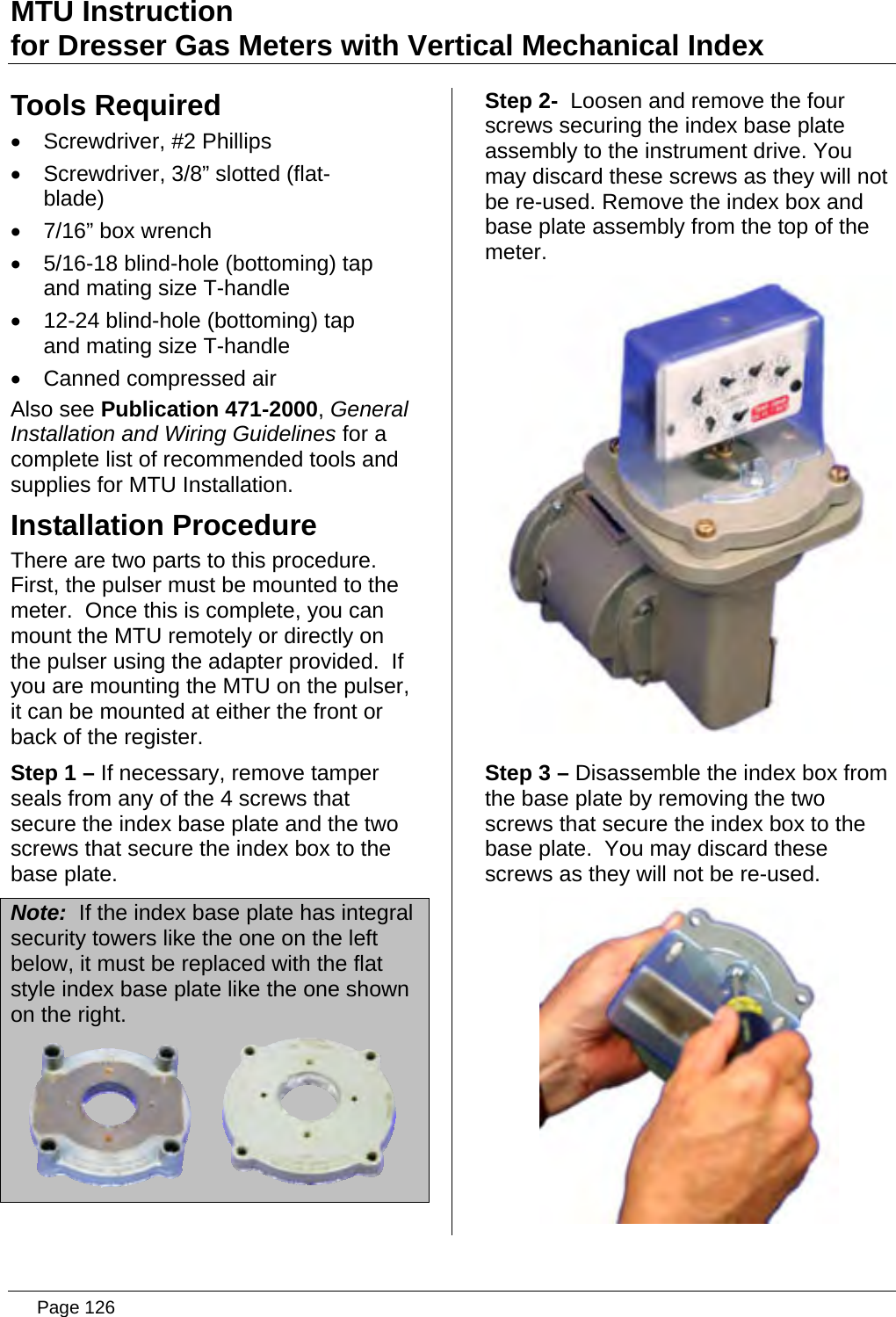
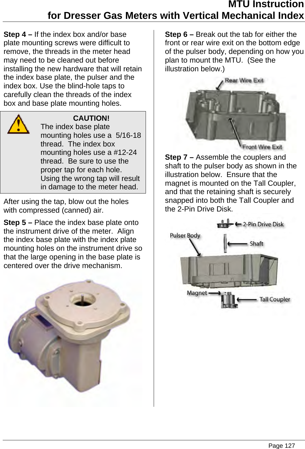
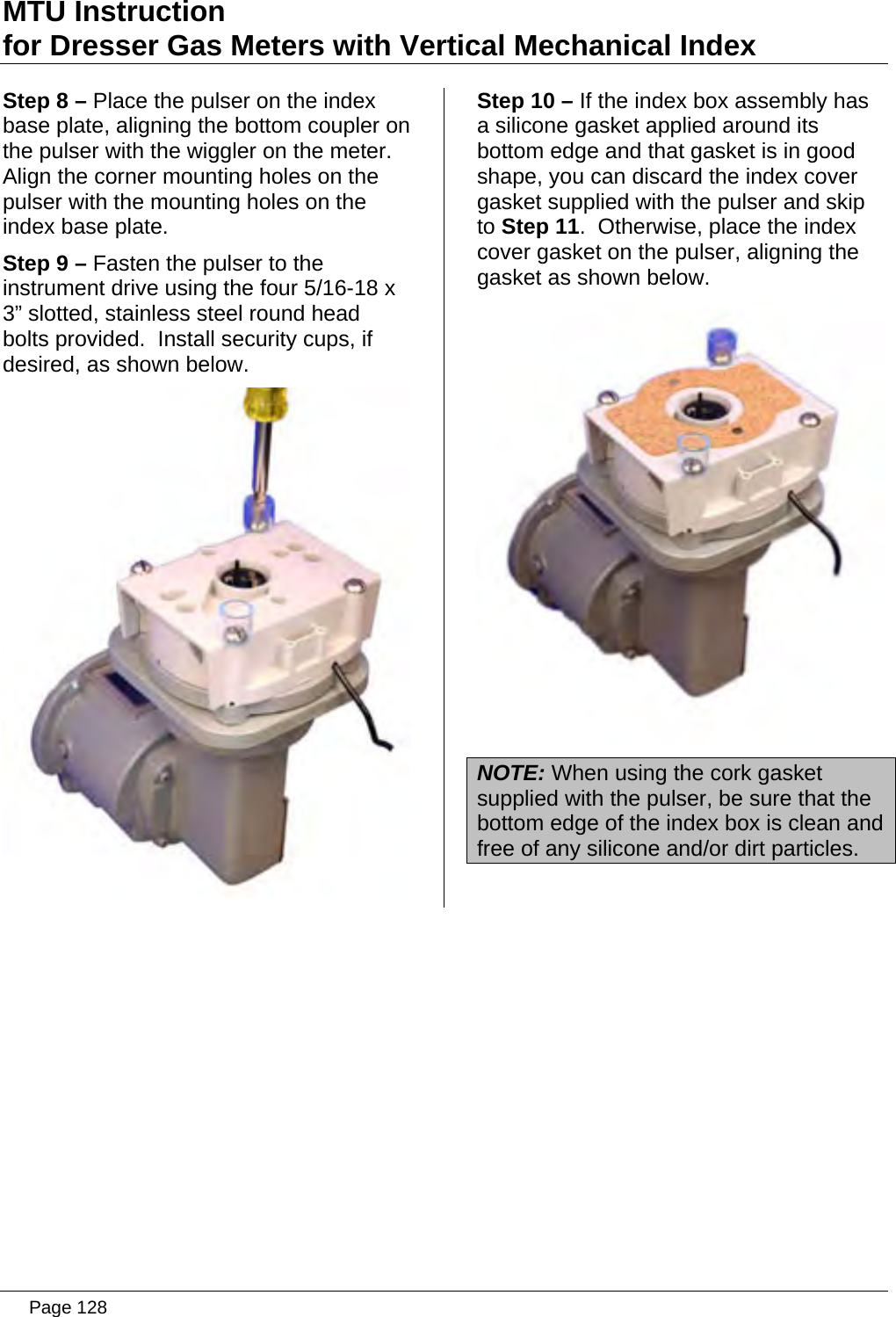
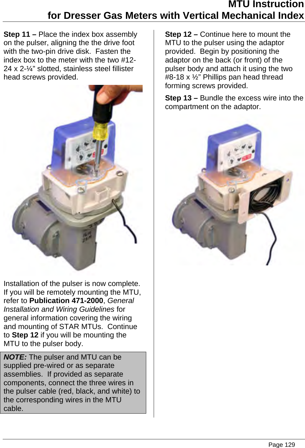
Aclara Technologies 09014 TRANSMITTER FOR METER READING User Manual Installation Instructions
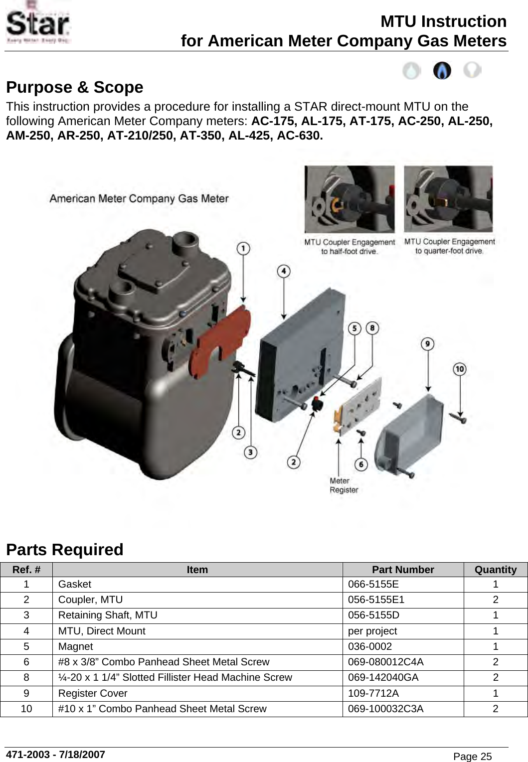
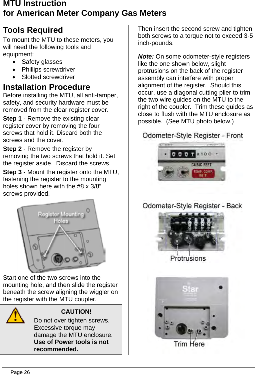
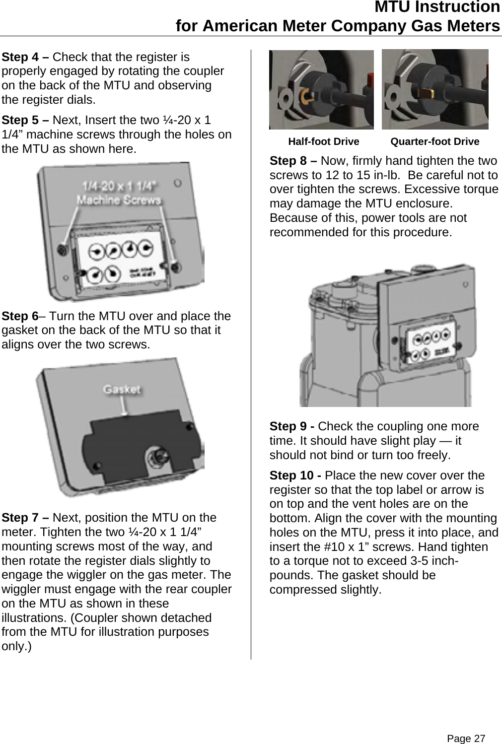
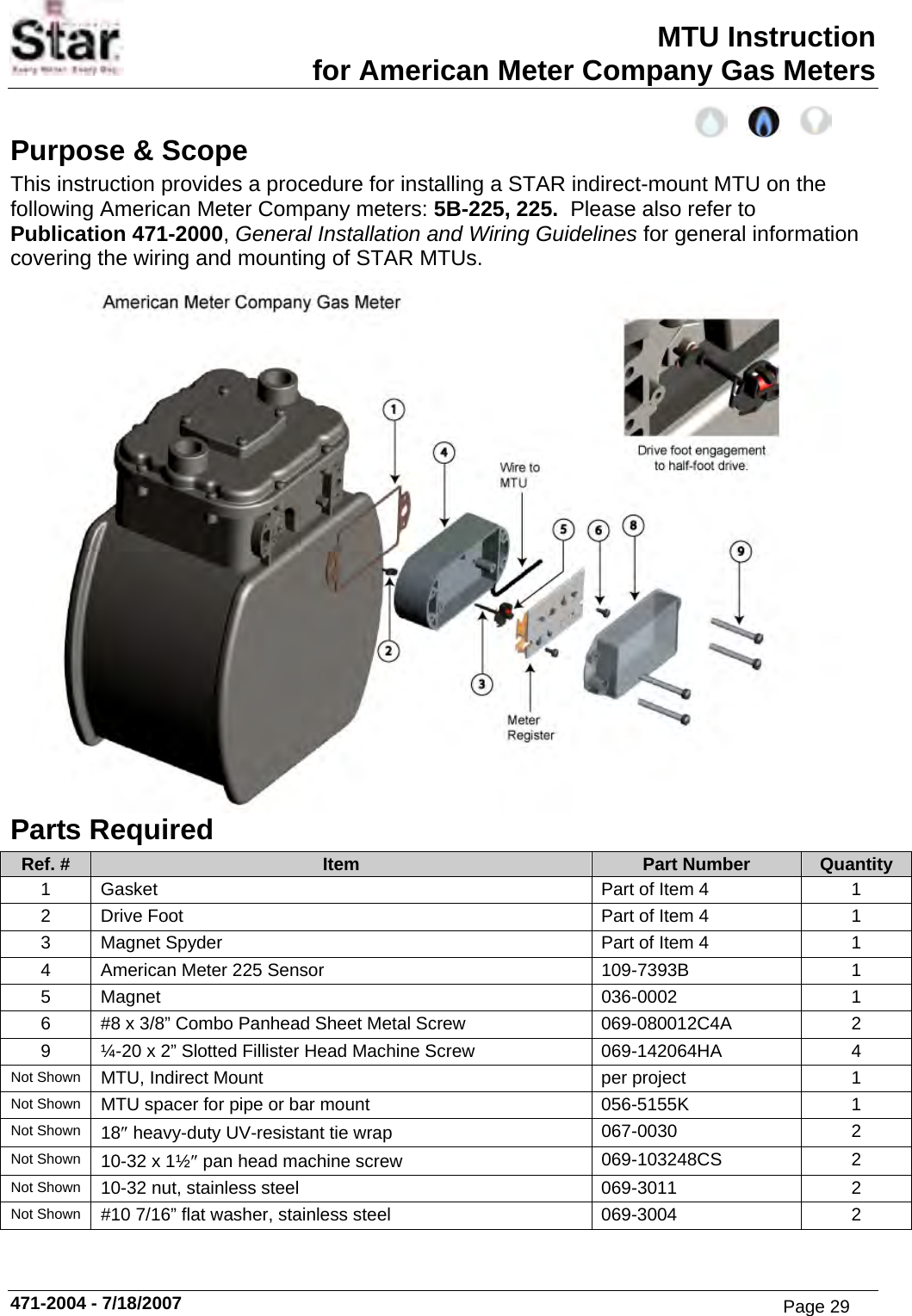
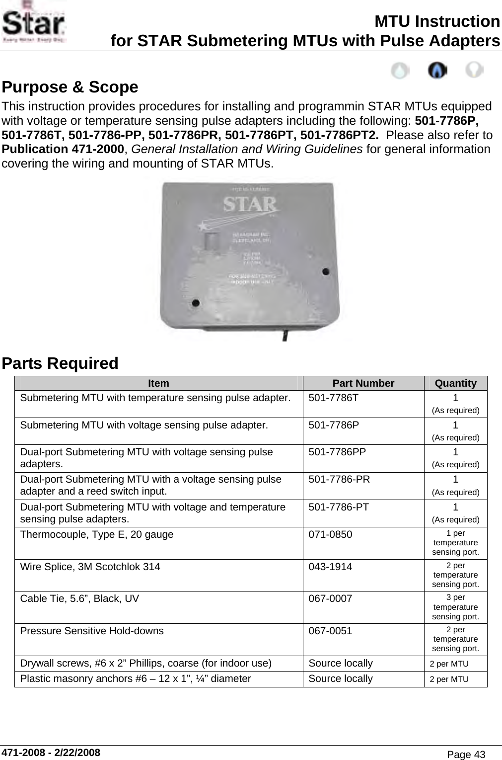
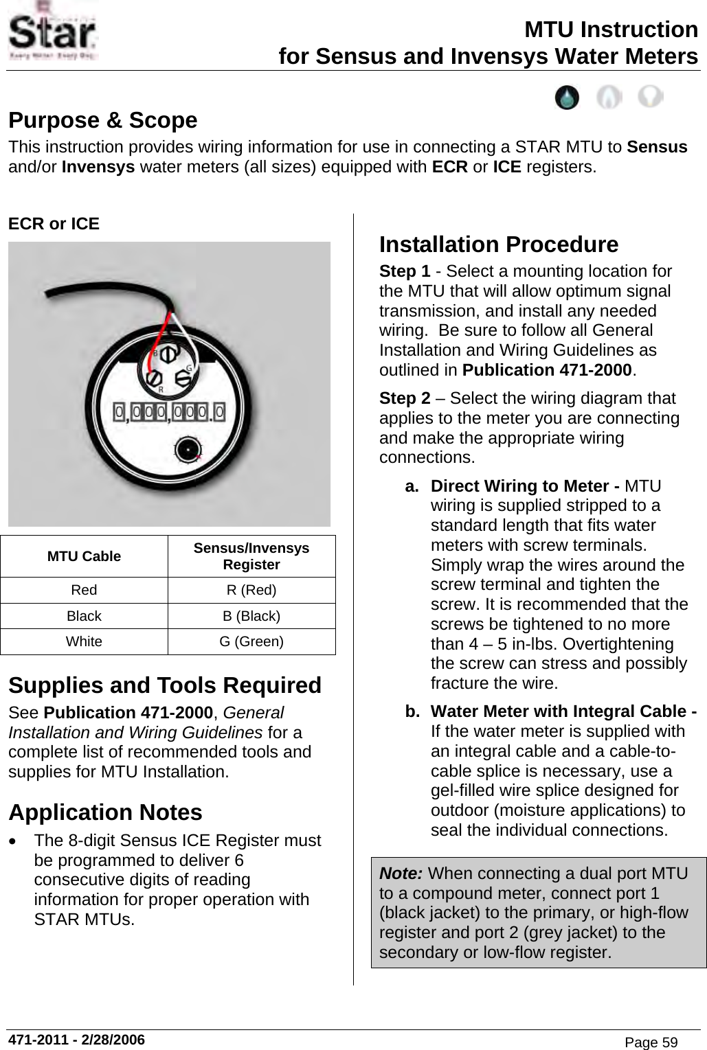
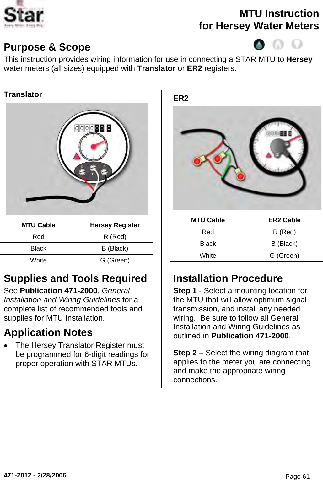
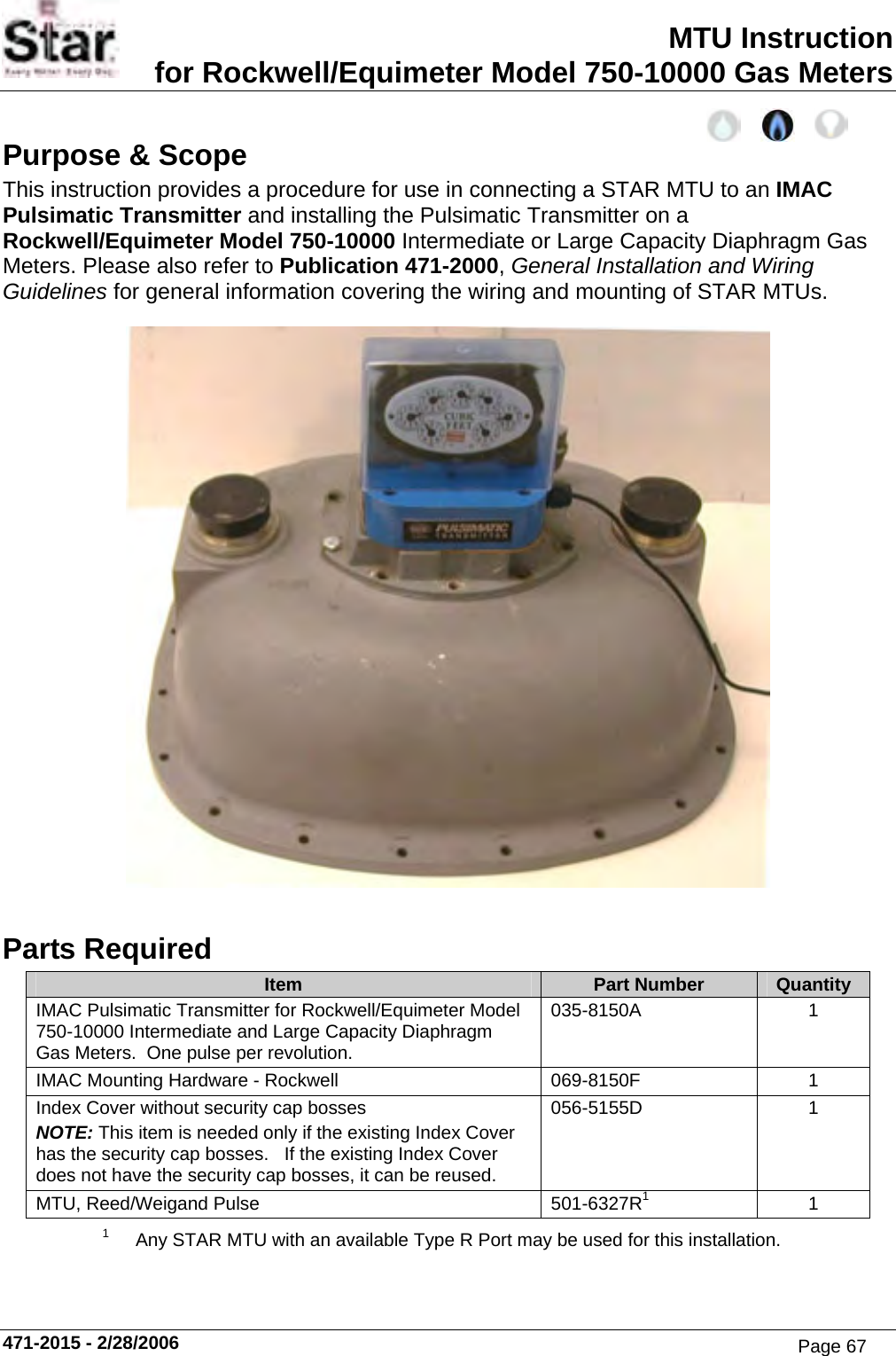
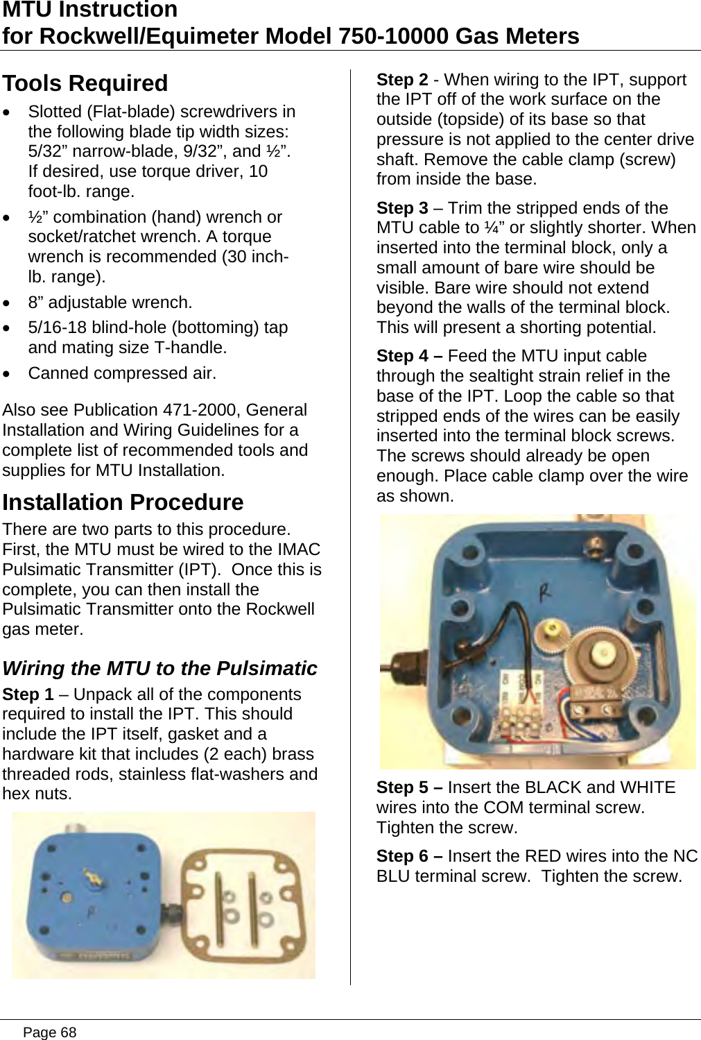
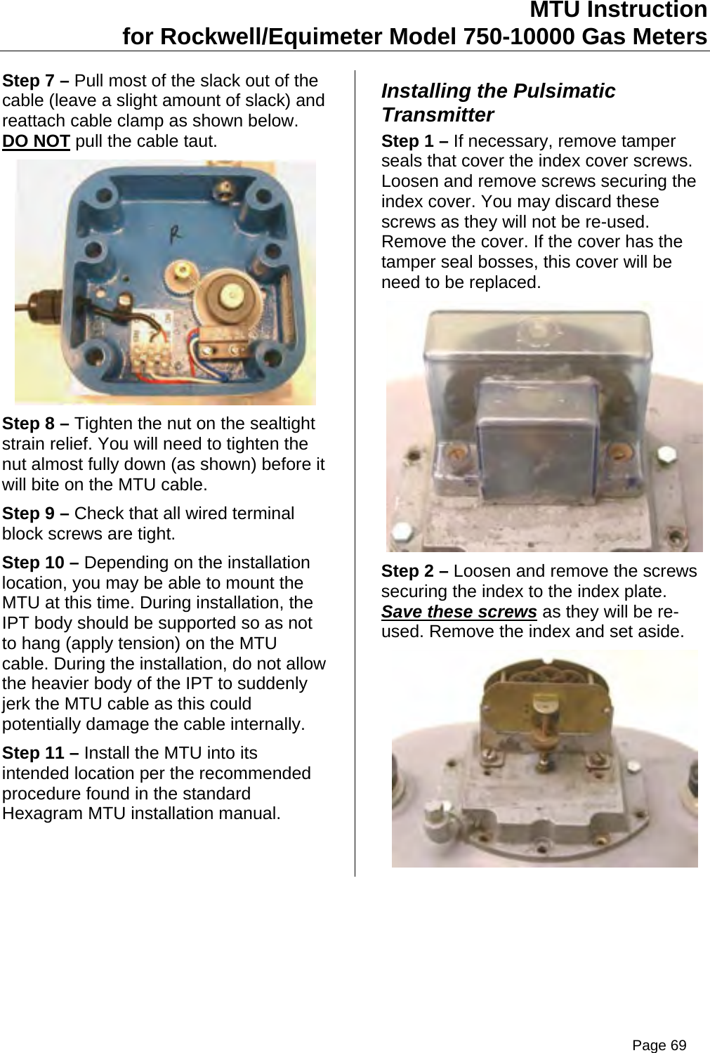
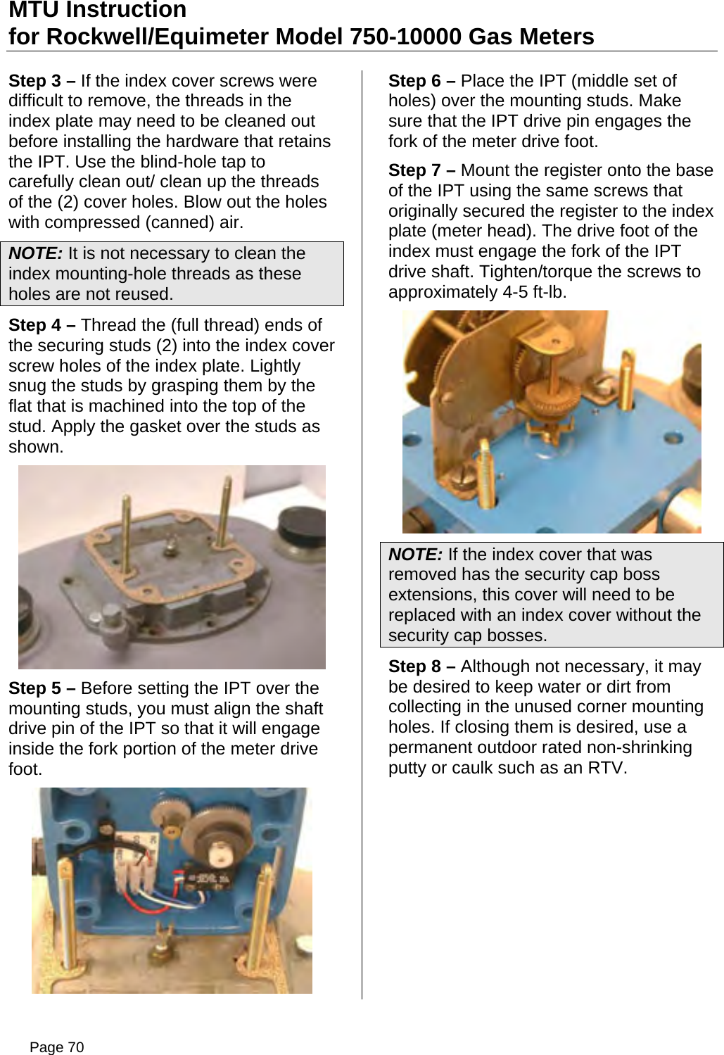
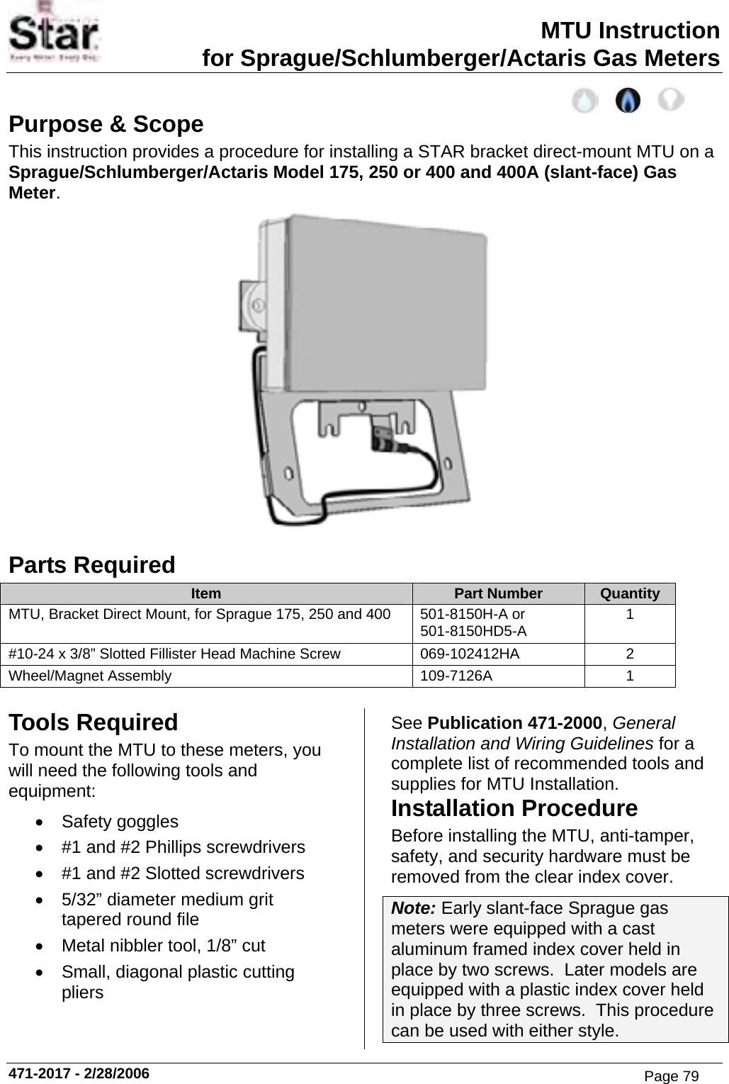
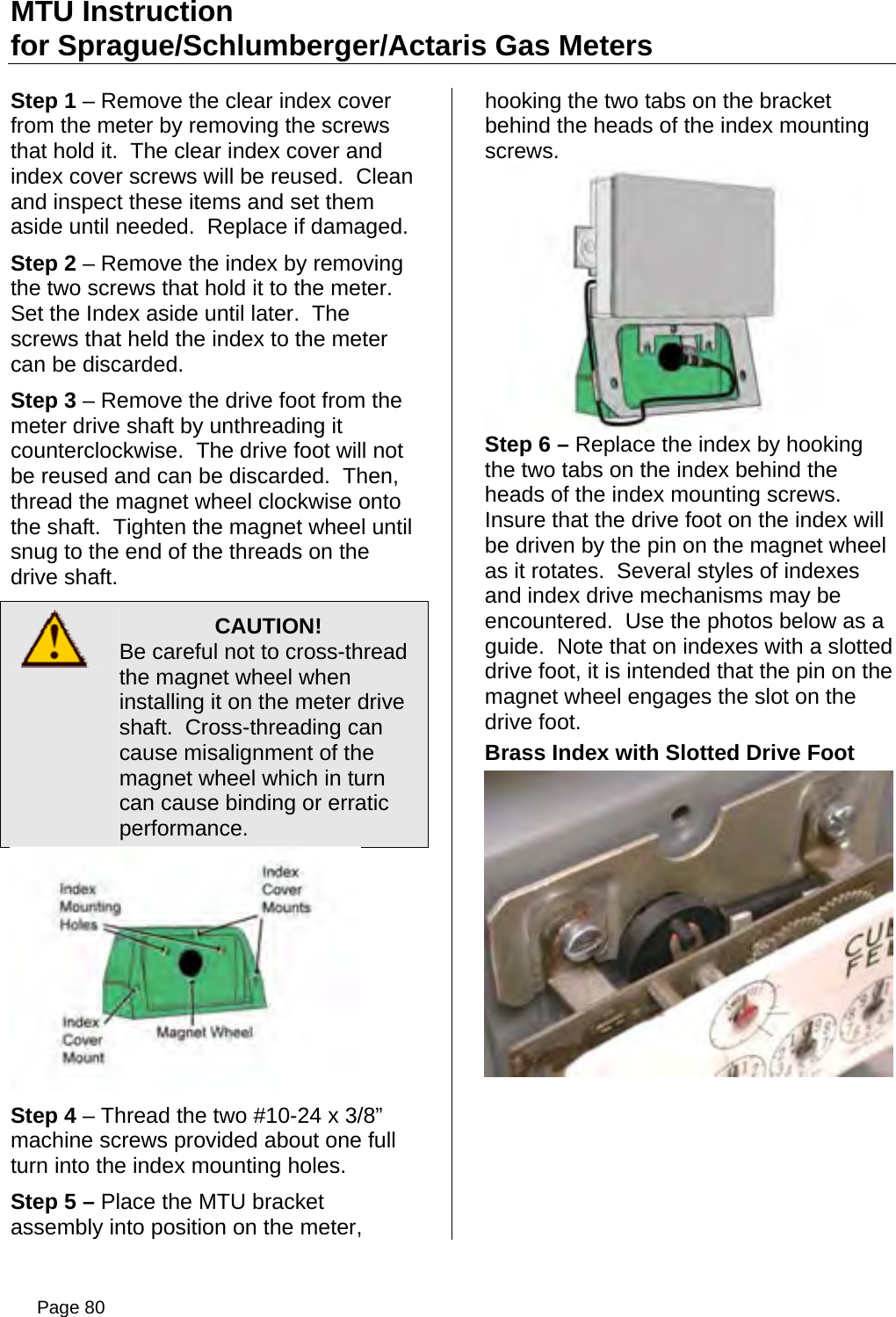
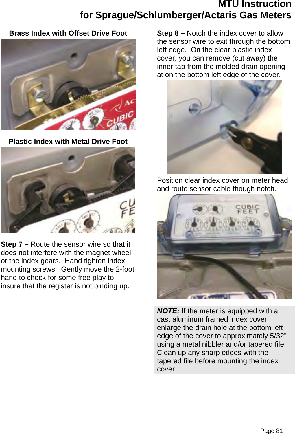
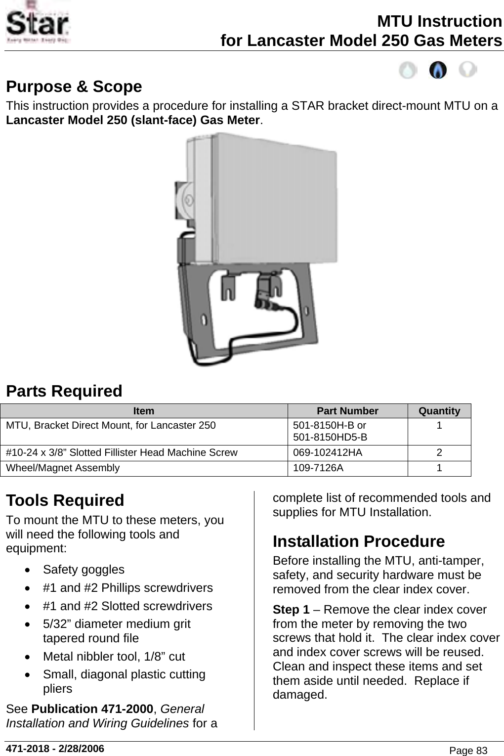
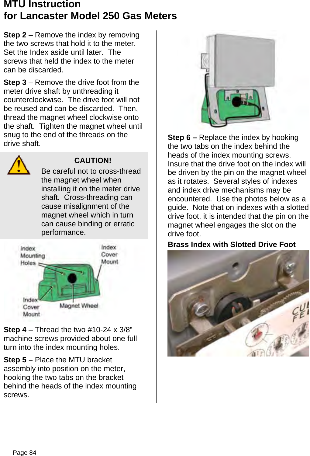
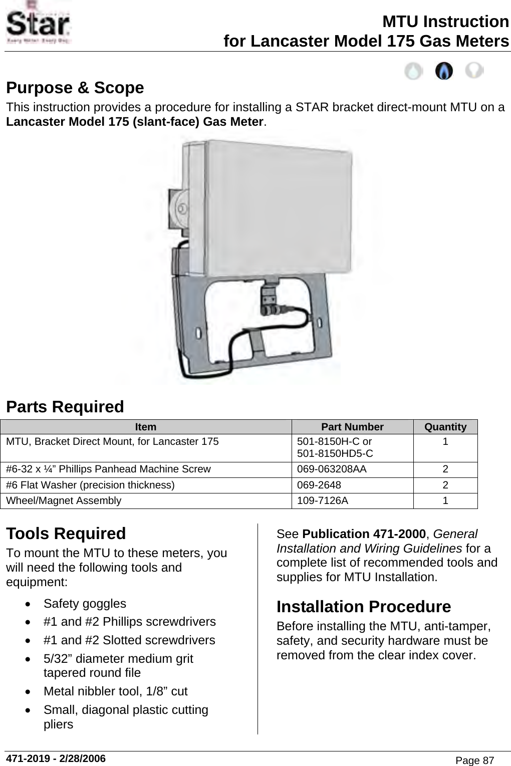
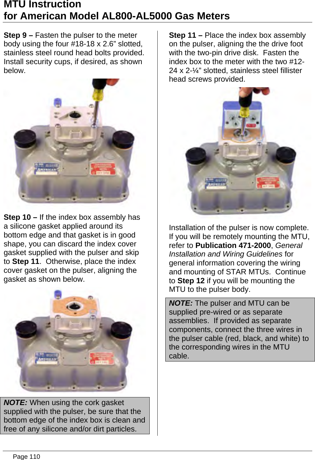
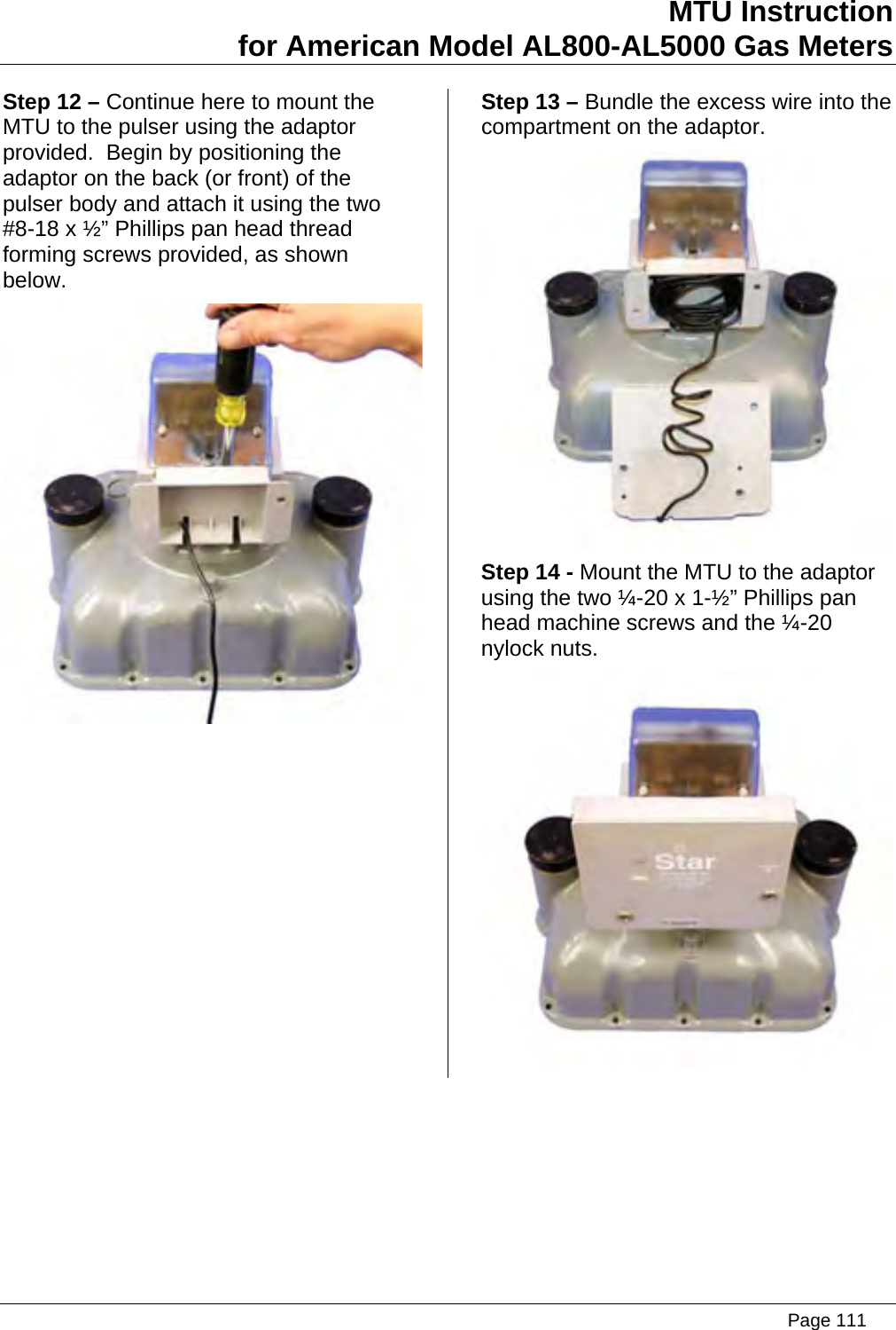
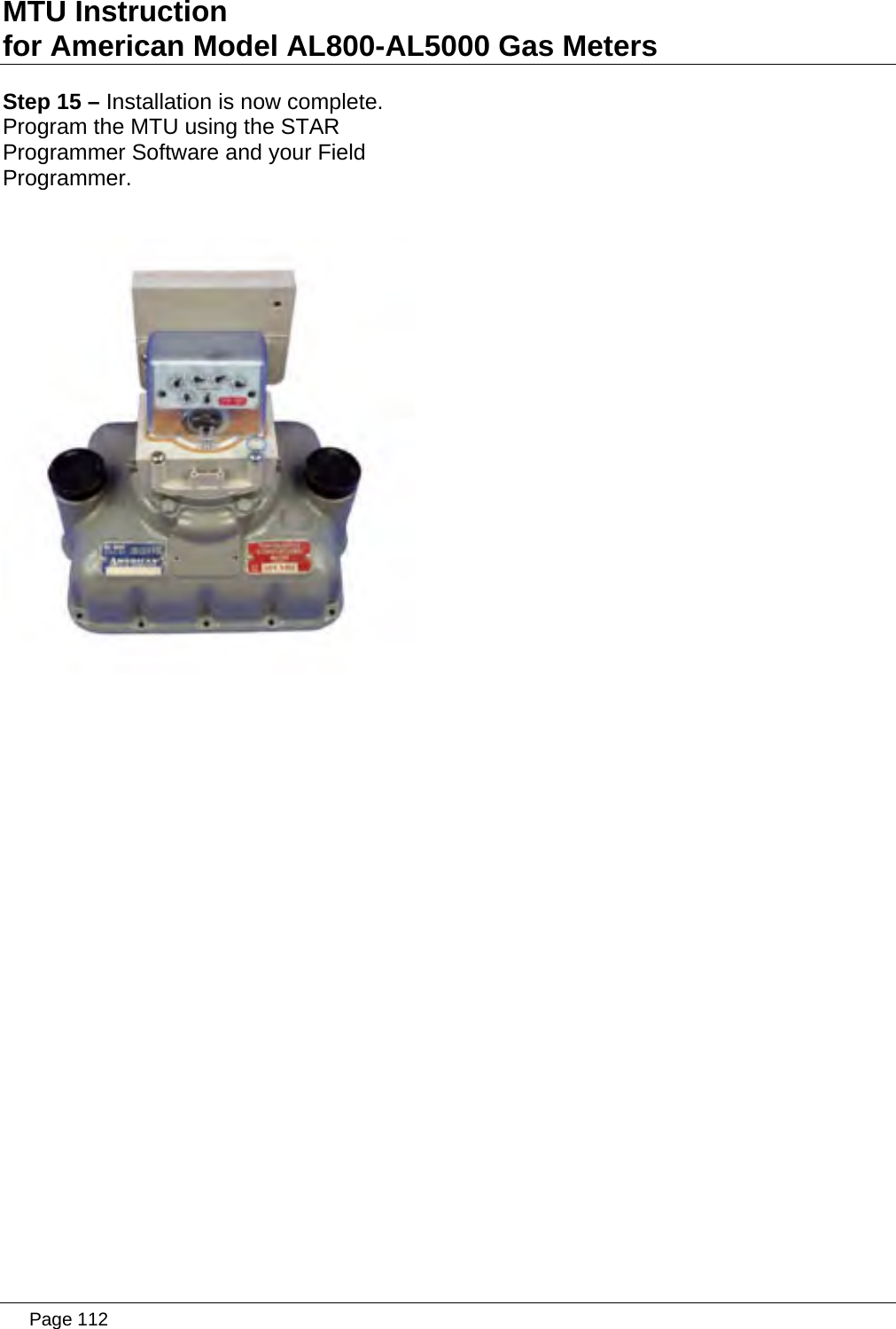
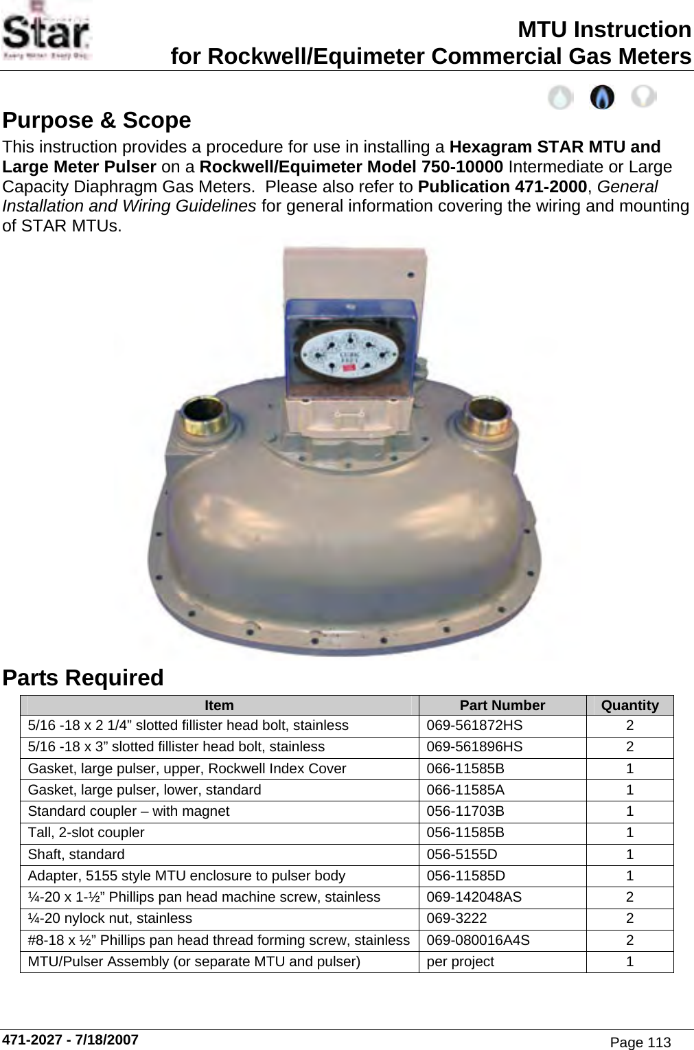
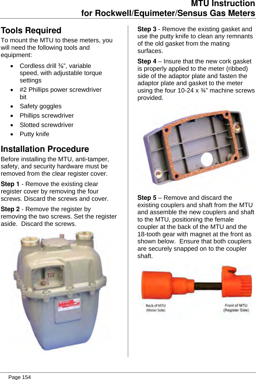
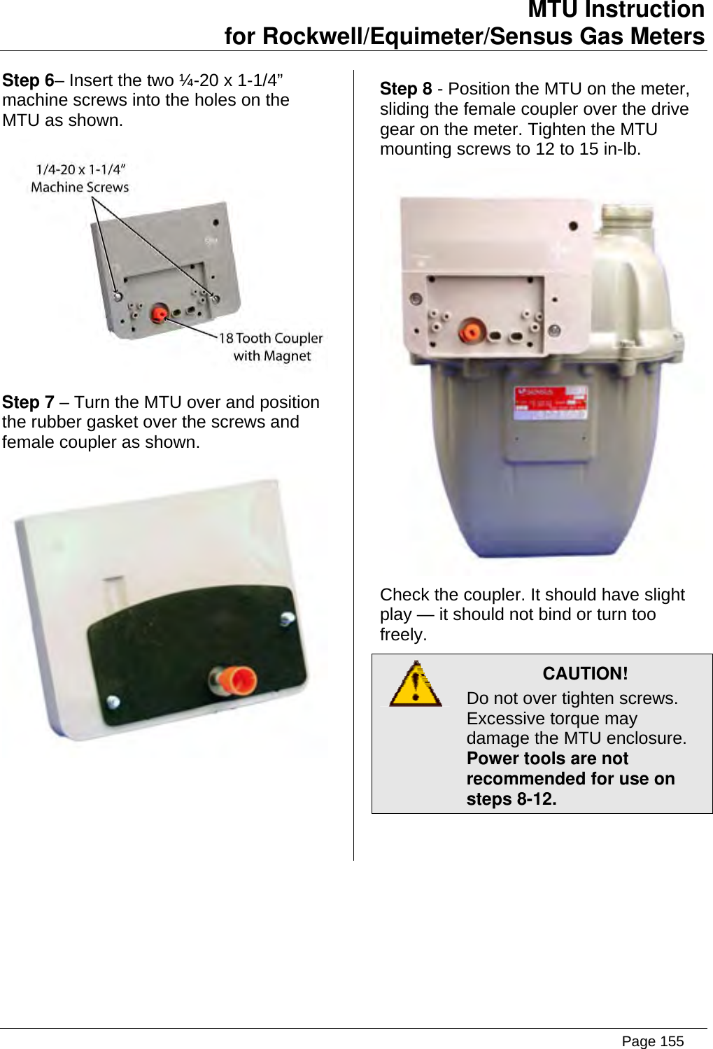
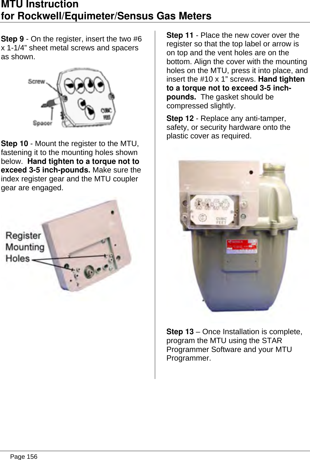
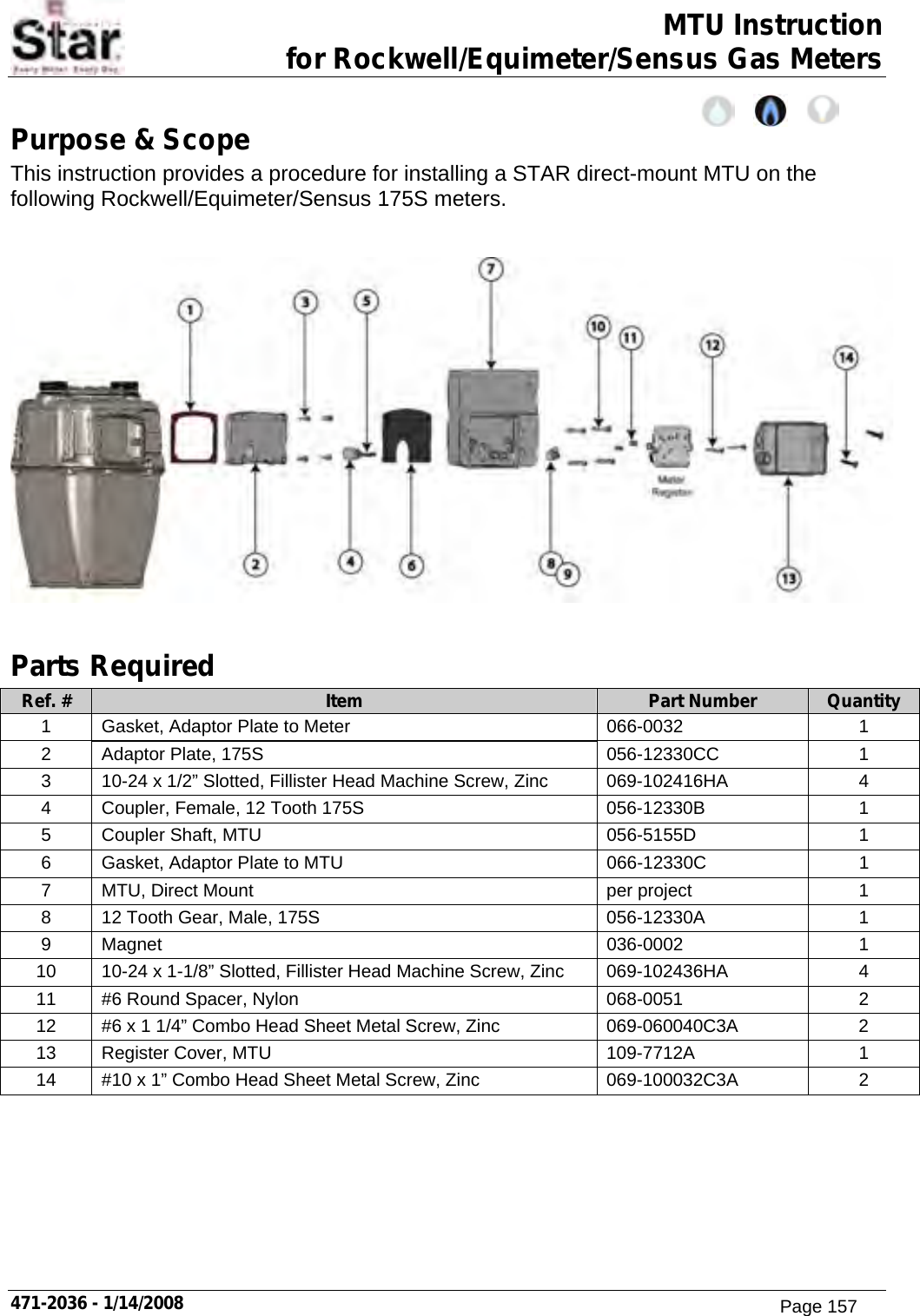
Aclara Technologies LLC TRANSMITTER FOR METER READING Installation Instructions
UserManual.wiki
>
Aclara Technologies
>
09014 User Manual
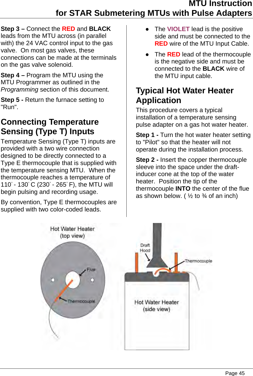
Installation Instructions
Navigation menu
Upload a User Manual
Namespaces
Wiki Guide
HTML
PDF
Info
Views
User Manual
Discussion / Help
Navigation