Aclara Technologies 09014 TRANSMITTER FOR METER READING User Manual Installation Instructions
Aclara Technologies LLC TRANSMITTER FOR METER READING Installation Instructions
Installation Instructions

MTU Instructions
ALL MTU Instructions as of 10/1/2009
October, 2009
Instructions Included
Document Page
471-2000 – General Installation & Wiring Guidelines ........................................................ 3
471-2001 – for Rockwell/Equimeter/Sensus Gas Meters (Direct Mount)..........................15
471-2002 – for Most Popular Water Meters........................................................................19
471-2003 – for American Meter Company Gas Meters (Direct Mount) ............................. 25
471-2004 – for American Meter Company Gas Meters (Indirect Mount)........................... 29
471-2005 – for Carson Industries Pit Lids.......................................................................... 33
471-2006 – for Armor Access Pit Lids................................................................................ 37
471-2007 – for Invensys/Icon MTU/Electric Meter.............................................................41
471-2008 – for Hexagram Submetering Pulse Adapters ..................................................43
471-2009 – for AMCO/ABB Water Meters........................................................................... 51
471-2010 – for Neptune/Schlumberger Water Meters....................................................... 55
471-2011 – for Sensus/Invensys Water Meters ................................................................. 59
471-2012 – for Hersey Water Meters................................................................................... 61
471-2013 – for Badger Water Meters .................................................................................. 63
471-2014 – for M-Log Sensors ............................................................................................ 65
471-2015 – for Rockwell/Equimeter Intermediate/Large Capacity Gas Meters..............67
471-2016 – for American Commercial/Industrial Gas Meters .......................................... 73
471-2017 – for Sprague/Schlumberger 250 Gas Meters (Bracket-direct-mount).............. 79
471-2018 – for Lancaster 250 Gas Meters (Bracket-direct-mount)..................................... 83
471-2019 – for Lancaster 175 Gas Meters (Bracket-direct-mount)..................................... 87
471-2020 – for Mini-Max.......................................................................................................91
471-2021 – for Sprague 175 Gas Meters (Indirect Mount).................................................. 95
471-2022 – for Metron-Farnier Water Meters ....................................................................101
471-2023 – for Nicor Composite Pit Lids .......................................................................... 103
471-2026 – for American Meter Commercial & Industrial Diaphragm Gas Meters
(Hexagram Large Meter Pulser)............................................................................................107
471-2027 – for Rockwell/Equimeter Intermediate and Large Capacity Gas Meters
(Hexagram Large Meter Pulser)............................................................................................109
471-2028 – for Actaris Commercial & Industrial Diaphragm Gas Meters
(Hexagram Large Meter Pulser)............................................................................................119
471-2029 – for Dresser Roots-type Gas Meters................................................................125
471-2030 – for Romet Roots-type Gas Meters.................................................................. 131
Page 1

MTU Instructions
ALL MTU Instructions as of 10/1/2009
Instructions Included (Continued)
Document Page
471-2031 – for Actaris/Schlumberger/Sprague ‘Slant-face’ Gas Meters........................137
471-2032 – for Armorcast Composite Pit Lids..................................................................141
471-2033 - for Actaris/Schlumberger/Sprague Pit/Curbside Gas Meters ......................145
471-2034 – for American Meter Company 5B-225 Gas Meters........................................149
471-2035 - for Sensus/Equimeter/Rockwell 415 Gas Meters...........................................153
471-2036 - for Sensus/Equimeter/Rockwell 175S Gas Meters ........................................157
471-2037 - for Sensus/Equimeter/Rockwell 175-EMCO Gas Meters...............................161
471-2038 - for Sensus/Equimeter/Rockwell Residential Gas Meters (Indirect Mount)...163
471-2040 – for Landis & Gyr Focus Family Electric Meters ............................................167
471-2041 – for Landis & Gyr S4 Family Electric Meters ..................................................169
471-2042 – for DFW Rectangular Composite Pit Lids......................................................171
471-2043 – for Carson Industries Polyplastic Pit Lids.....................................................175
471-2044 – for Sensus/Equimeter/Rockwell Gas Meters (Metric - direct mount) ............179
471-2045 – for Mid-States 12" Round Pit Lids..................................................................183
471-2046 – for Alliance Rectangular Pit Lids....................................................................187
471-2047 - for Actaris/Schlumberger/Sprague ‘Flat-face’ Gas Meters...........................189
471-2051 – for Actaris Dattus fm2 and fm3 Commercial & Industrial
Diaphragm Gas Meters .......................................................................................................195
471-2052 – for Severn-Trent SmartMeter Water Meters...................................................197
471-2053 – for Endress & Hauser PROMAG Water Meters .............................................199
471-2054 – for Actaris Cyble Water Meters.......................................................................201
Page 2

MTU Instructions
General Installation and Wiring Guidelines
The FCC wants you to know…..
This equipment has been tested and complies with Part 15 and Part 90 of the FCC Rules. These limits are
designed to provide reasonable protection against harmful interference. This equipment generates, uses
and can radiate radio frequency energy, and, if not installed and used in accordance with the instructions,
may cause harmful interference to radio communications. However, there is no guarantee that interference
will not occur in a particular installation. If this equipment does cause harmful interference to radio or
television reception, try to correct the interference by one or more of the following measures:
• Reorient or relocate the equipment.
• Increase the separation distance between the affected equipment and receiver.
• Consult Hexagram, Inc. for help.
Any changes or modifications to this equipment not expressly approved by the Hexagram, Inc. could void the
authorization to operate the equipment.
FCC RF Exposure Guidelines
Hexagram’s low power RF devices and their antennas must be fixed-mounted on indoor or outdoor
permanent structure(s) providing a separation distance of at least 20 cm from all persons during normal
operation. This device is not designed (and it has no external connection) to operate in conjunction with any
other antennas or transmitters. No other operating instructions for satisfying RF exposure compliance are
needed. This unit has no user or installer serviceable parts, and requires no field adjustment or calibration.
Units are sealed at the factory, and disruption of this seal could void the authorization to operate the
equipment.
Hexagram, Inc.
23905 Mercantile Road
Cleveland, OH 44122
Intentionally Left Blank
Page 14

MTU Instructions
General Installation and Wiring Guidelines
Purpose & Scope
This instruction outlines general practices and procedures for the installation and wiring of
standalone, electronic interface Hexagram STAR MTUs. When installing an MTU,
always refer to these instructions in addition to any specific instructions for the
meter/MTU combination you will be installing and programming.
Note: STAR MTUs are shipped to the customer in sealed enclosures and have passed
extensive testing and calibration procedures at the factory. No additional calibration or
adjustment is required, or can be made, without breaking thefactory seal. As calibrated,
these devices radiate a tiny fraction of the power allowable byFCC Radio Frequency
Exposure Limits 47 CFA CH 1.1310. There are no radio-frequency safety issues relating
to the use of this product based on this regulation.
471-2000 - 7/25/2007
Page 3

MTU Instructions
General Installation and Wiring Guidelines
Recommended Supplies
We recommend the following supplies, for which quantities will depend upon the number of
MTUs to be installed and the conditions encountered at each installation location.
Item Hexagram Part
Number Quantity
AMP Tel-Splice, 2-conductor 043-1910 As needed
Scotchlok, UR 2-3 wire gel-filled butt connector 043-1913 As needed
3-conductor, 22 ga, solid wire, black UV jacket 070-0506 As needed
3-conductor, 22 ga, solid wire, grey UV jacket 070-0508 As needed
AA alkaline battery, 1.5 volt (for Psion) 042-0036 As needed
Back-up battery for Psion MTU Programmer 042-0037 As needed
3M DBR-6 Direct Burial Kit (for pit unit splices) 043-1912 As needed
Sealant — White RTV 084-0082 As needed
Black electrical tape As needed
Tie-wraps, black As needed
Staples, telephone type, 9/16” (Arrow T-25) As needed
Sharpie permanent marker, fine point As needed
Plastic masonry anchors #6 x 1”, ¼” diameter As needed
for use with Original Flatpak MTUs
Hexagram plastic spacers 056-5155H1 As needed
Phillips exterior screws 8 x 2 ½” (deck screw) As needed
Phillips exterior screws 8 x 3” (deck screw) As needed
Drywall screws, #6 x 1-5/8” Phillips, coarse (for indoor use) As needed
Drywall screws, #6 x 2” Phillips, coarse (for indoor use) As needed
MTU spacer for pipe or bar mount 056-5155K As needed
18″ heavy-duty UV-resistant tie wrap (for bar mounting gas
MTUs)
067-0030 As needed
10-32 x 1½″ pan head machine screw (for bar mounting gas
MTUs)
069-103248CS As needed
10-32 nut, stainless steel (for bar mounting gas MTUs) 069-3011 As needed
#10 7/16” flat washer, stainless steel (for bar mounting gas
MTUs) 069-3004 As needed
for use with NEW Compact Flatpak MTUs
Long Spacers/Standoffs (for pit lid installations) 056-8150L As needed
Short Spacers/Standoffs (for pit lid installations) 056-8150S As needed
Phillips exterior screws 8 x 1 3/4” (deck screw) As needed
Drywall screws, #6 x 1-5/8” Phillips, coarse (for indoor use) As needed
Page 4

MTU Instructions
General Installation and Wiring Guidelines
Recommended Tools
• Cordless drill (⅜”, variable speed,
1800-2000 rpm, adjustable torque
settings)
• Drill bit, ¼”, carbide tipped
• Drill bit, ¼” x 12”, carbide tipped
• #2 Phillips power screwdriver bits
• Stapler for ¼” wire and cable
(Arrow T-25M)
• Diagonal side cutters/wire cutters
• Needle nose pliers – small
• Wire stripper
• Connector crimping tool 3M 9EY
• Safety goggles
• Screwdriver, #1 Phillips
• Screwdriver, #2 Phillips
• Screwdriver, 5/16” slotted
• Screwdriver, ¼” slotted
• Screwdriver, small slotted, ⅛”
blade
• Hammer
• Clipboard
• Flashlight with batteries
• Extension cord with trouble light
• MTU Programmer with cable,
programming coil and STAR
Programming Software
MTU Wiring
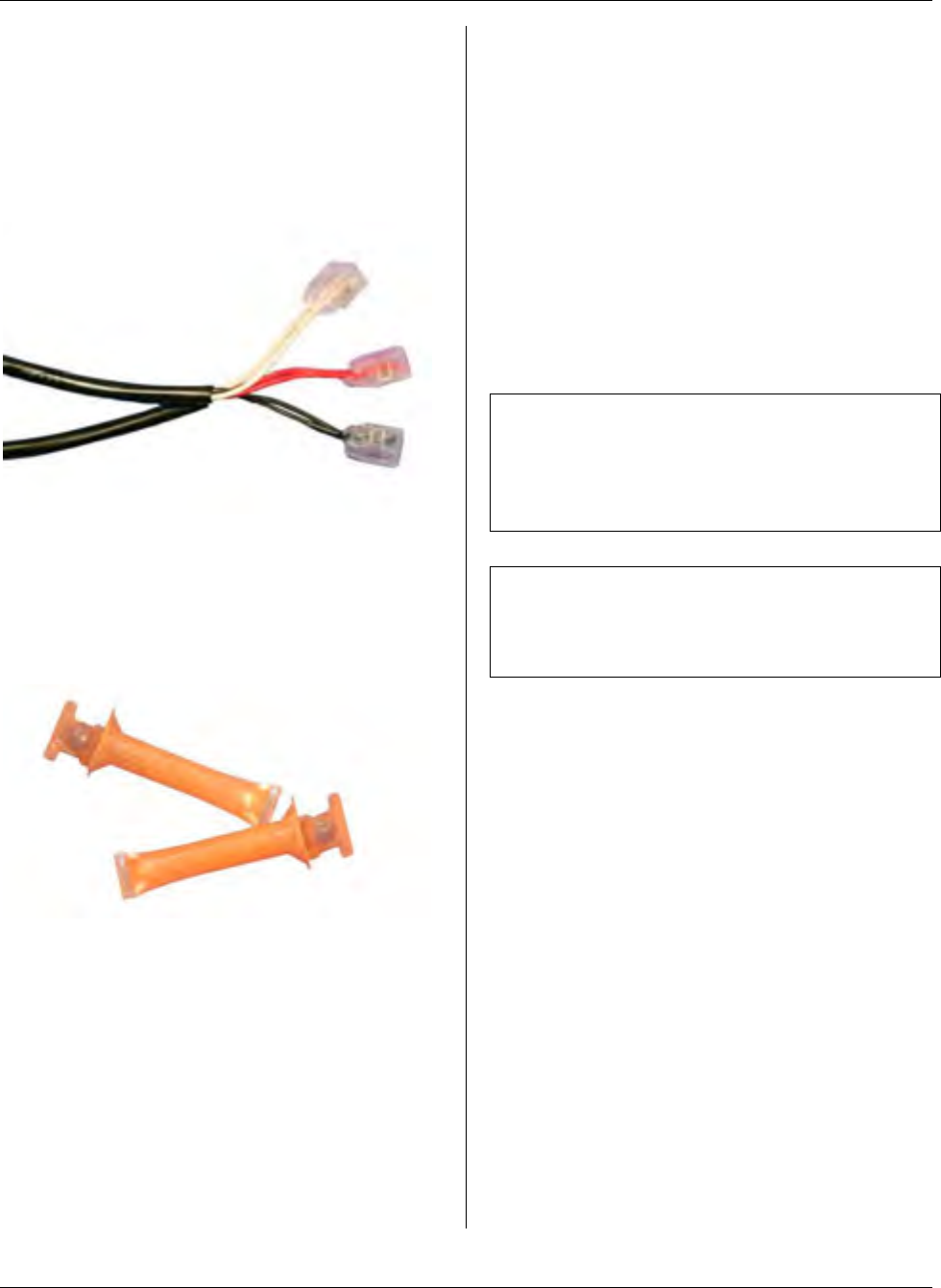
General - Many MTUs connect to the
meter by means of a 3-conductor, 22-
gauge solid conductor wire. The wire is
housed in a PVC jacket with UV
inhibitors. A black-jacketed wire is
supplied on single-port MTUs and for port
1 of dual-port MTUs. A grey jacket is
used for the port two input to dual port
MTUs.
Wire Length – MTUs are provided with a
standard wire length of 12 feet. Additional
wire may be used if necessary. A
maximum run of up to 500 feet can be
used to position the MTU in a favorable
location. Use like-colors for cable jackets
and individual wires when extending MTU
wiring.
Some specific meters may impose other
wire length limitations. Consult the meter
manufacturer.
Wire Routing - Wires should be attached
to walls with 9/16” staples. If wire
clearance holes are needed to route wire
from the meter to the MTU, drill a ¼” hole
using an appropriate drill bit. The installer
is responsible for the selection of an
appropriate location for any hole to be
drilled.
Note: Wiring must be in accordance with
all national and local codes.
Wire Protection - A drip loop below the
MTU is not required.
Inspect wire to ensure that routing and
stapling have not caused wire damage.
Pull the wire lightly at each staple to
make sure that the staple is not set too
tightly.
Any splices made to wire must be
suitable for the environment and made in
accordance with national and local codes.
Page 5
MTU Instructions
General Installation and Wiring Guidelines
They must be secure and made in
accordance with the connection supplier’s
instructions. Generally, gel-filled
Insulation Displacement Connectors
(IDCs) such as 3M ScotchLok or AMP
Tel-Splice connectors should be used on
all wire-to-wire connections.
Splices located outdoors or in meter pits
should be further protected through the
use of a direct burial kit. This consists of
a gel-filled plastic tube that houses the
individual wire-to-wire splices to provide
additional protection from the elements.
MTU Positioning and
Mounting
General - MTUs must be positioned and
mounted properly to ensure optimum RF
signal propagation. Each MTU contains
an internal antenna near the top front
surface of the sealed enclosure. As a
result, the MTU should always be
mounted vertically and the STAR logo
should face the installer.
Since MTU transmissions are similar in
nature to cellular phone signals, a cellular
phone can be used to help to determine if
a location is suitable for MTU mounting.
If the cellular phone signal drops
dramatically or indicates no signal at the
desired location, it is possible that the
MTU signal will also be blocked at this
location. In this case, the MTU will have
to be mounted in a different location,
possibly on the outside of the structure.
Keep the MTU away from all other
electrical wires.
Note: Do not mount the MTU under
wiring such as Romex, AC power wires,
cable TV wire, or telephone wire. Do not
allow these wires to lay on top of, or in
front of the MTU.
Note: Keep the MTU six inches away
from metal items such as pipes, conduit,
electric meters, electrical boxes, and
downspouts.
Make sure screws used to mount the
MTU do not protrude and pierce or
otherwise damage any wires, cables, or
pipes.
Use of Spacer – There are two primary
styles of MTUs. The Original Flatpak
STAR MTU requires the use of a spacer
(Hexagram Part Number 056-5155H1)
when the MTU is mounted on any surface
other than wood. The NEW Flatpak
STAR MTU is a modified design that can
be directly mounted to a variety of
surfaces without the use of a spacer.
See the examples below for additional
information.
Page 6
MTU Instructions
General Installation and Wiring Guidelines
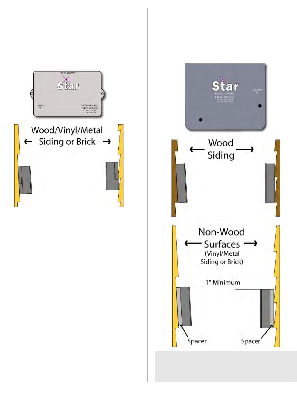
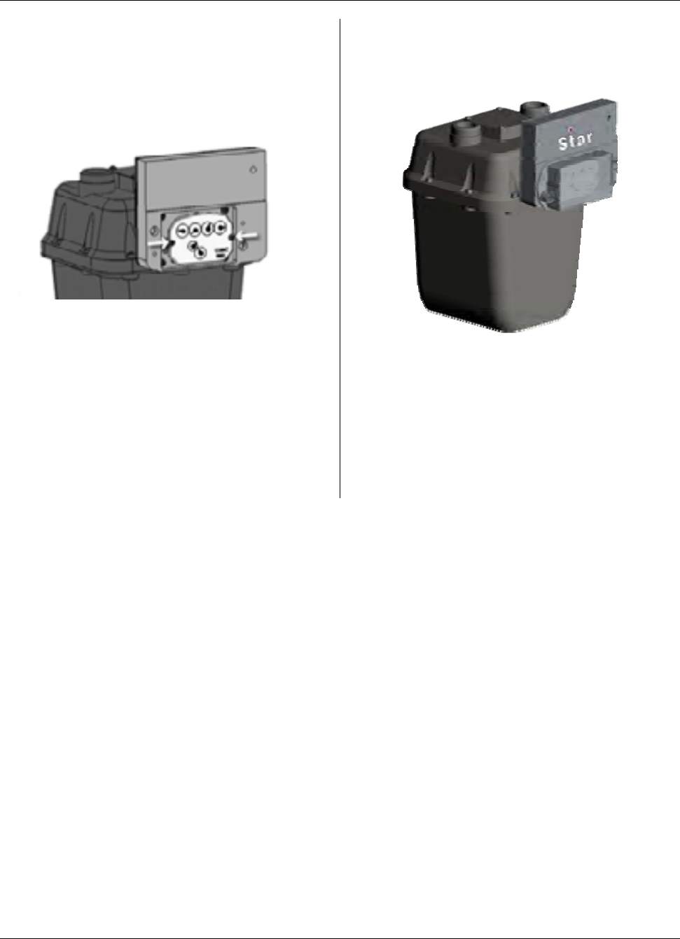
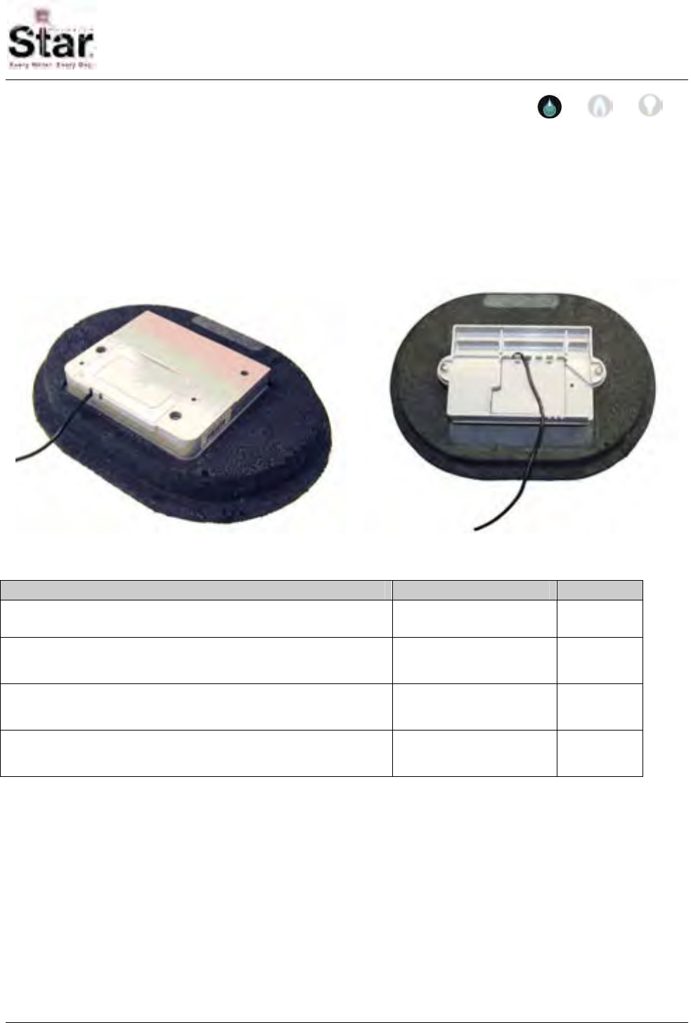
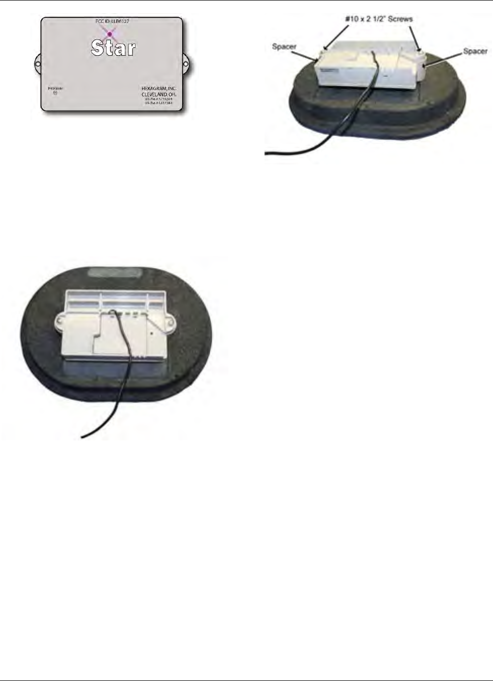
NEW Flatpak STAR MTU – An example
of the NEW Flatpak STAR MTU is shown
below. These MTUs are approximately
6.5” x 4.25” x 1.5” thick, and can be
mounted on most surfaces without the
use of a spacer.
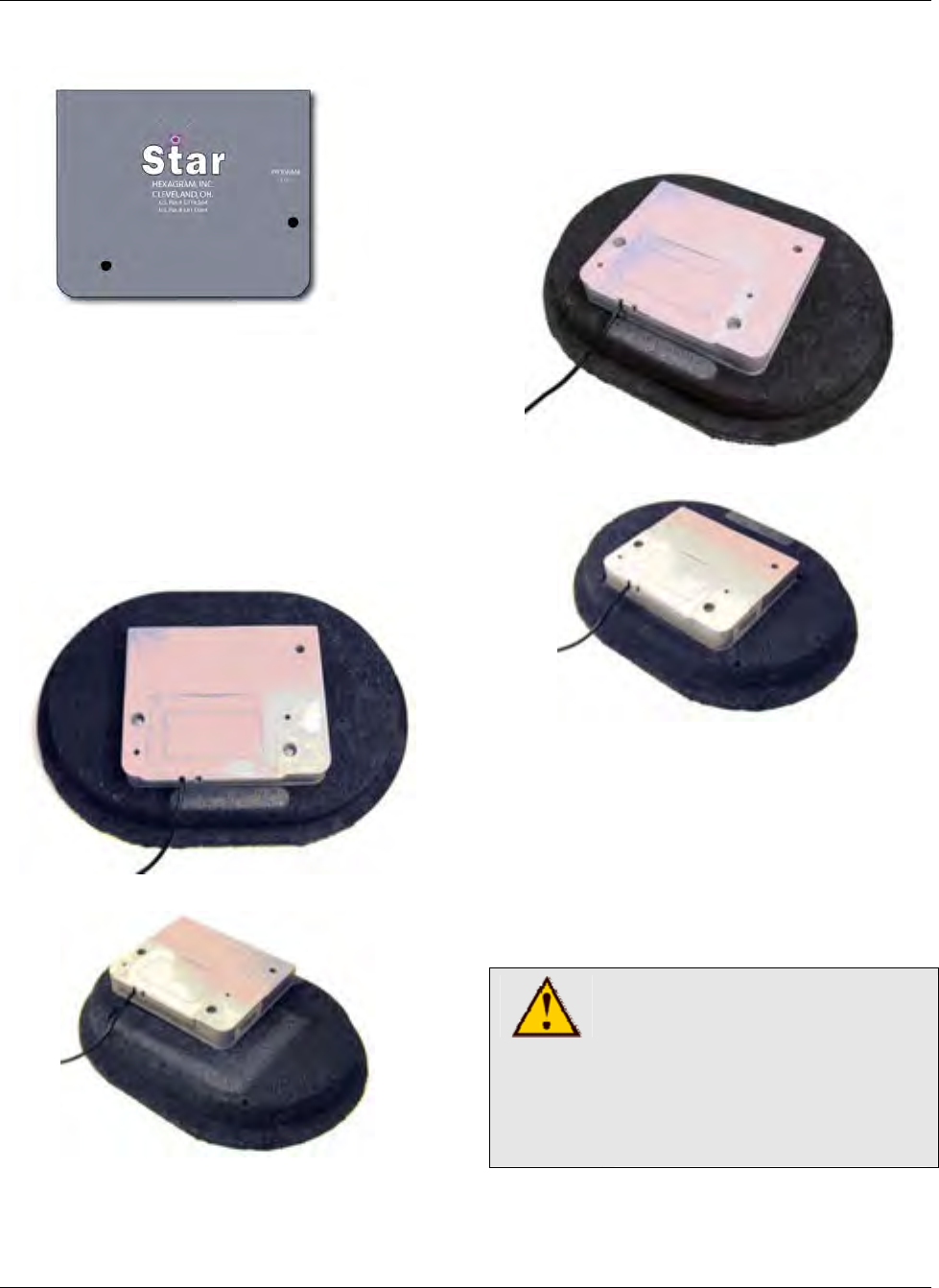
Original Flatpak STAR MTU – An
example of an Original Flatpak STAR
MTU is shown below. These MTUs are
6.5” x 5.5” X 1” thick, and require a
spacer if mounted on any material other
than wood.
Note: Do not use a spacer when
mounting an Original Flatpak STAR MTU
on wood.
Page 7
MTU Instructions
General Installation and Wiring Guidelines
Outdoor Mounting
MTUs mounted outdoors are typically
mounted to the side of buildings, to a
stationery post, to the piping surrounding
the meter, or to a pit lid.
Mounting to a Buiding or Post
If the unit is being mounted to the outside
of a building, the MTU will be connected
to wires that lead from the inside to the
outside of the building. If existing wire is
used, it must be of the same quality as
specified in MTU Wiring. It must also be
in good condition, without breaks,
damage, or corrosion.
Step 1 – Select a mounting location for
the MTU that will allow optimum signal
transmission.
Step 2 – Run wiring from the MTU to the
meter. If a splice is required, it may be
placed inside or outside. For special
circumstances, contact your supervisor.
If using existing wiring, remove any box
that houses the outside wires.
Step 3 – Mount the MTU on the side of
the building.
• The MTU must be mounted
level, vertically with the STAR
logo facing the installer. Allow a
1” space between the top of the
MTU and the overhang of the
siding above it. This is critical
for proper radio signal
transmission.
• Use a Spacer (Hexagram Part
Number 056-5155H1) if
mounting an Original Flatpak
STAR MTU on a non-wood
surface.
CAUTION!
Do not over tighten screws.
Excessive torque will crack
the MTU enclosure. Do not
tighten screws beyond the
point that the MTU touches
the mounting surface.
Step 4 – Make the appropriate
connections to the meter. Refer to the
specific MTU Instruction for the meter in
use.
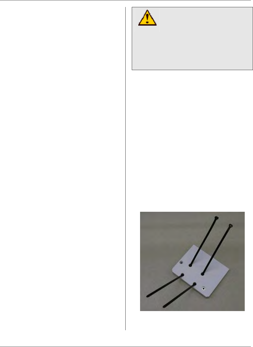
Bar or Pipe Mounting
Particularly in outdoor gas applications, it
is sometimes convemient to mount the
MTU to the connecting piping. With the
Original Flatpak STAR MTU this is easily
done using a bar-mount spacer and two
18” long tie-wraps, (See Recommended
Supplies.)
Step 1 - Thread the tie-wraps into the bar
mount spacer as shown here.
Page 8
MTU Instructions
General Installation and Wiring Guidelines
Step 2 - Attach the spacer to the MTU
using #10-32 stainless steel screws, nuts
and washers. Tighten the screws to 12 to
15 in-lb. On a standard drill driver with 0
to 24 torque settings, this is typically the
#10 setting.
Step 3 - Wrap the tie wraps around the
bar as needed, pulling the ties around
(through the spacer plate) as they are
tightened.
Step 4 - Adjust the MTU as needed and
pull the tie wraps tight.
Step 5 - Trim off the excess tie wrap,
leaving about a ½” tab.
Step 6 – Once Installation is complete,
program the MTU using the STAR
Programmer Software and your MTU
Programmer.
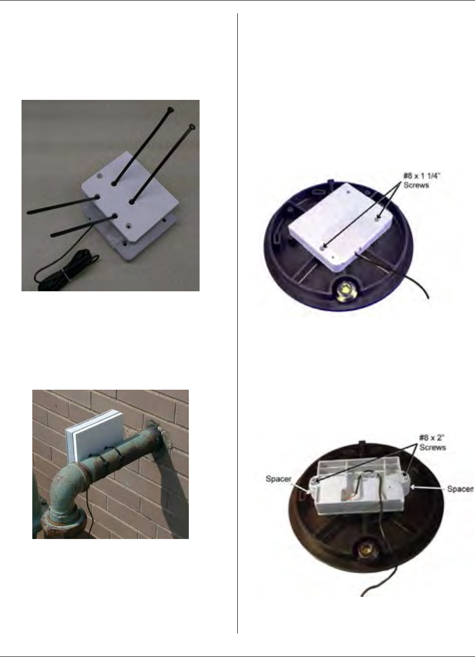
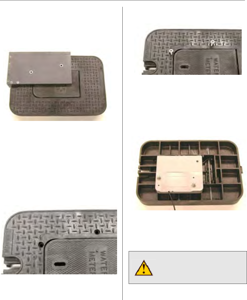
Pit-Lid Mounting
For water or gas meters located in meter
pits, MTUs can be mounted to the lower
surface of the pit lid if an approved, non-
metallic pit lid is used. In these
applications, the MTU is mounted with it’s
front surface facing the bottom surface of
the lid, as shown below
Original Flatpak STAR MTU
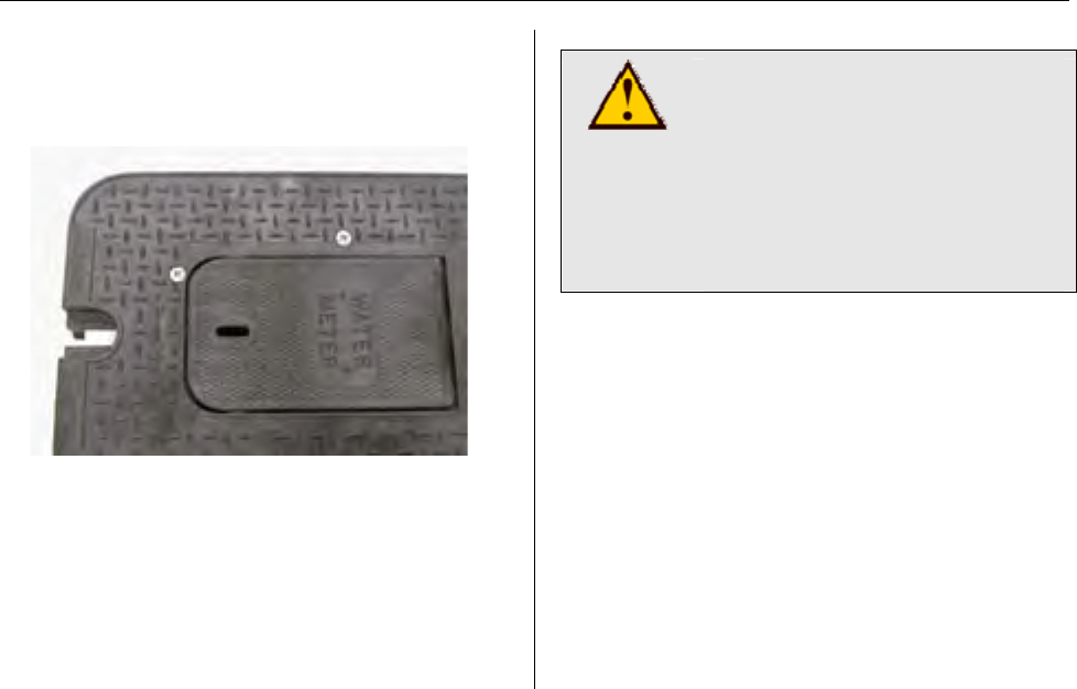
When NEW Flatpak STAR MTUs are
mounted in this manner, spacers are
used between the MTU mounting tabs
and the lower surface of the pit lid, as
shown below.
Revised Flatpak STAR MTU
Page 9
MTU Instructions
General Installation and Wiring Guidelines
A long spacer is available, for use when
the lower surface of the pit lid is a flat,
solid surface. A short spacer is used
when the lower surface of the pit lid in
use has a ribbed construction.
Contact Hexagram for information on
approved non-metallic pit-lids.
Indoor Mounting
For an inside mount, mount the MTU
vertically on a ceiling joist. It is important
to mount the MTU as high as possible.
Note: The MTU must be mounted above
grade.
Because the outside wall of a building
can have metal siding or foil insulation,
keep the MTU a few inches away from
the outside wall. Transmissions easily
pass through wood and masonry.
Do not install an MTU inside if the
basement has a metal ceiling or foil-lined
insulation in the ceiling or if it has foil on
the sidewalls running from grade to
ceiling. This will prevent the signal from
transmitting effectively.
Large metal objects such as heating
ducts, steel cabinets or metal ceiling
structures can block MTU transmissions.
Select locations that are at least five to
ten feet away from objects such as these.
Do not mount the MTU if large metal
objects, such as heating ducts, block both
the front and rear of the MTU. If
absolutely necessary, a single large metal
object may be located several feet away
from the MTU.
Unfinished Basement
Step 1 – Select a mounting location for
the MTU that will allow optimum signal
transmission. In unfinished basements,
this is typically high on a ceiling joist, at
least a few inches away from outside
walls.
Step 2 – Mount the MTU.
• The MTU must be mounted
level, vertically with the STAR
logo facing the installer. Allow a
1” space between the top of the
MTU and any overhang above
it. This is critical for proper
radio signal transmission.
• Use a Spacer (Hexagram Part
Number 056-5155H1) if
mounting an Original Flatpak
STAR MTU on a non-wood
surface.
CAUTION!
Do not over tighten screws.
Excessive torque will crack
the MTU enclosure. Do not
tighten screws beyond the
point that the MTU touches
the mounting surface.
Page 10

MTU Instructions
General Installation and Wiring Guidelines
Step 3 – Run wiring from the MTU to the
meter. Carefully staple the wire to the
wall every 18” and at every change in
direction using 9/16” staples. All turns
are to be at right angles. If wire must be
run on masonry, secure it with wire clips.
Run wires parallel to the joist. If a joist
must be crossed, run at a 90 degree
angle. If the MTU input cable must be
extended, use an appropriate splice.
Make sure inner conductors are not
nicked during stripping.
Step 4 – Make the appropriate
connections to the meter. Refer to the
specific MTU Instruction for the meter in
use.
Finished Basement
Step 1 – Select a mounting location for
the MTU that will allow optimum signal
transmission. In Finished basements,
this may be high on a ceiling joist in an
unfinished section of the basement or
high on an interior wall near a window or
outside wall, but at least a few inches
away from outside walls.
Note: Ceilings may contain metal.
Therefore, the MTU should be placed 2 to
3 inches down from a plaster or ‘dropped’
ceiling.
Step 2 – Mount the MTU.
• The MTU must be mounted
level, vertically with the STAR
logo facing the installer. Allow a
1” space between the top of the
MTU and any overhang above
it. This is critical for proper
radio signal transmission.
• Use a Spacer (Hexagram Part
Number 056-5155H1) if
mounting an Original Flatpak
STAR MTU on a non-wood
surface.
CAUTION!
Do not over tighten screws.
Excessive torque will crack
the MTU enclosure. Do not
tighten screws beyond the
point that the MTU touches
the mounting surface.
Step 3 - Run wiring from the MTU to the
meter. Run all wiring behind the wall if
possible. Carefully staple the wire to the
wall every 18” and at every change in
direction using 9/16” staples. All turns are
to be at right angles. If wire must be run
on masonry, secure it with wire clips. Run
wires parallel to the joist. If a joist must be
crossed, run at a 90 degree angle. If the
MTU input cable must be extended, use
an appropriate splice. Make sure inner
conductors are not nicked during
stripping.
Step 4 – Make the appropriate
connections to the meter. Refer to the
specific MTU Instruction for the meter in
use.
Page 11

MTU Instructions
General Installation and Wiring Guidelines
Do
9 Do check your cell phone for presence
of a strong signal before entering a
building or basement. Do install the
MTU if the signal remains strong at
the installation location. (Note: This is
a guideline only. It does not guarantee
that the MTU will be received by the
DCU. However, if cell phone service is
affected by the location, it is possible
that the MTU transmission will also be
blocked.)
9 Do select the best possible location
for MTU installation that will allow
optimum signal transmission.
9 Do select a location for MTU
installation that is above grade.
9 Make sure that the MTU is located
near an outside wall, but not on an
outside wall.
9 Make sure the MTU in installed within
500 feet of the meter.
9 Do make sure that no staples have
pierced the installation wire.
9 Do mount the MTU vertically and level
with the STAR Logo facing the
installer.
9 Do keep the MTU a few inches away
from the outside wall in case of metal
siding or foil insulation.
9 Do use a spacer when mounting an
Original Flatpak STAR MTU on any
surface other than plaster or wood.
9 Do use a spacer if you need to make
a splice near the MTU and if the MTU
is mounted outside.
9 Do keep the MTU at least 6” (the
width of the MTU) from all pipes,
conduit, electric meters, electrical
boxes, downspouts, dumpsters,
garbage cans, water, electric and gas
meters, etc.
9 Do keep at least 4” between MTUs
side to side and 3” top to bottom,
when installing multiple MTUs.
9 Do mount an MTU 2” to 3” below a
plaster ceiling or the metal grid of a
drop ceiling.
9 Do use amp splices and 3M DBR Gel
kits when making splices in pits.
9 Do make sure the correct meter type
and size is selected.
9 Do make sure the MTU is
programmed on.
9 Do program the MTU as the last step.
Make sure it is mounted, wired, all
splices are completed and tucked into
place and wires are stapled in place.
9 Do follow all national and local codes
when installing MTUs.
9 Do inspect all splices, connections
and wiring for damage.
9 Do route all wires away from the MTU
case.
Page 12

MTU Instructions
General Installation and Wiring Guidelines
Don’t 9 Don’t make a connection or splice if
any of the wires are nicked or cut. Re-
strip the wire and start over.
9 Don’t install the MTU if the cell phone
signal was strong outside the building
or basement and then goes into “no
service” or a very weak signal at the
MTU installation site.
9 Don’t damage insulation with staples,
or by rough handling.
9 Don’t stretch wire when installing.
9 Don’t exceed 500 feet total wire length
between the MTU and the meter.
9 Don’t select a location for MTU
installation that is easy to install, but
will not allow for good signal
transmission.
9 Don’t select a location for MTU
installation that is below grade.
9 Don’t place the MTU under Romex,
AC power wires, cable or TV wire,
telephone wire, etc. Don’t allow these
wires to lay on top of or in front of the
MTU.
9 Don’t mount the MTU right next to
conduit or metal pipes.
9 Don’t over tighten the screws when
mounting the MTU.
9 Don’t route the MTU wire along the
top or front of the MTU.
9 Don’t mount the MTU near 2 or more
metal objects such as heating ducts.
9 Don’t mount the MTU behind metal
objects such as washers, dryers,
furnaces, hot water tanks, metal sinks,
metal shelves, dumpsters, garbage
cans, water, electric or gas meters, or
any other large metal objects.
9 Don’t mount the MTU in a basement
that has metal ceilings unless there is
an opening in the ceiling that is above
grade where the MTU can be
installed.
9 Don’t mount the MTU near electrical
wires.
9 Don’t stack MTUs on top of each other
(back to front).
9 Don’t install an MTU if the case is
cracked or broken.
9 Don’t mount the MTU in the center of
a basement.
Page 13
MTU Instruction
for Rockwell/Equimeter/Sensus Gas Meters
471-2001 - 7/14/2008
Purpose & Scope
This instruction provides a procedure for installing a STAR direct-mount MTU on the
following Rockwell/Equimeter/Sensus meters: R175, R200, R250, R275, R310, R315,
RT210.
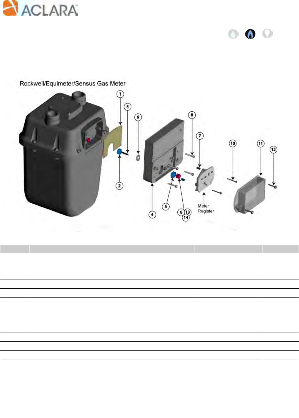
Parts Required
Ref. # Item Part Number Quantity
1 Gasket (pre-applied to MTU) 066-5155C 1
2 Blue Coupler, MTU 056-5155E 2
3 Retaining Shaft, MTU 056-5155D 1
4 MTU, Direct Mount per project 1
5 Magnet 036-0002 1
6 Gear, Blue, Standard 056-5155G4 1
7 #6 Round Spacer, Nylon 068-60812-EX 2
8 10-24 x 1 1/8” Slotted, Fillister Head Machine Screw 069-102436H 4
9 #10 Flat Washer, Acetal 069-3019 1
10 #6 x 1 1/4” Combo Panhead Sheet Metal Screw 069-060040C3 2
11 Register Cover, MTU 109-7712A 1
12 #10 x 3/4” Tri-lobular Screw 069-101424A2 2
13 Gear, Red, Extended 056-5155G3 1
14 Gear, Yellow, Odometer 056-5155G2 1
Page 15
MTU Instruction
for Rockwell/Equimeter/Sensus Gas Meters
Tools Required
To mount the MTU to these meters, you
will need the following tools and
equipment:
• Cordless drill ⅜”, variable
speed, with adjustable torque
settings
• #2 Phillips bit
• Safety goggles
• Phillips screwdriver
• Slotted screwdriver
Installation Procedure
Before installing the MTU, anti-tamper,
safety, and security hardware must be
removed from the clear register cover.
Step 1 - Remove the existing clear
register cover by removing the four
screws. Discard the screws and cover.
Step 2 - Remove the register by
removing the two screws. Set the register
aside. Discard the screws.
Step 3 - Insert the four 10-24 x 1⅛”
screws through the holes on the MTU as
shown.
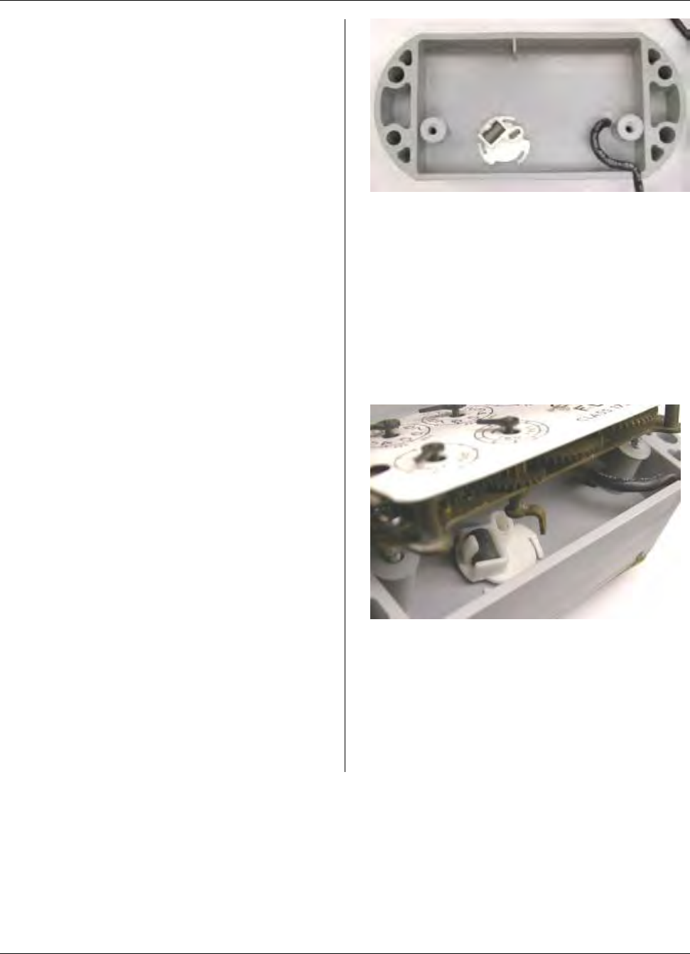
Step 4 – Turn the MTU over and insure
that there is a pre-applied gasket on the
back of the MTU as shown below.
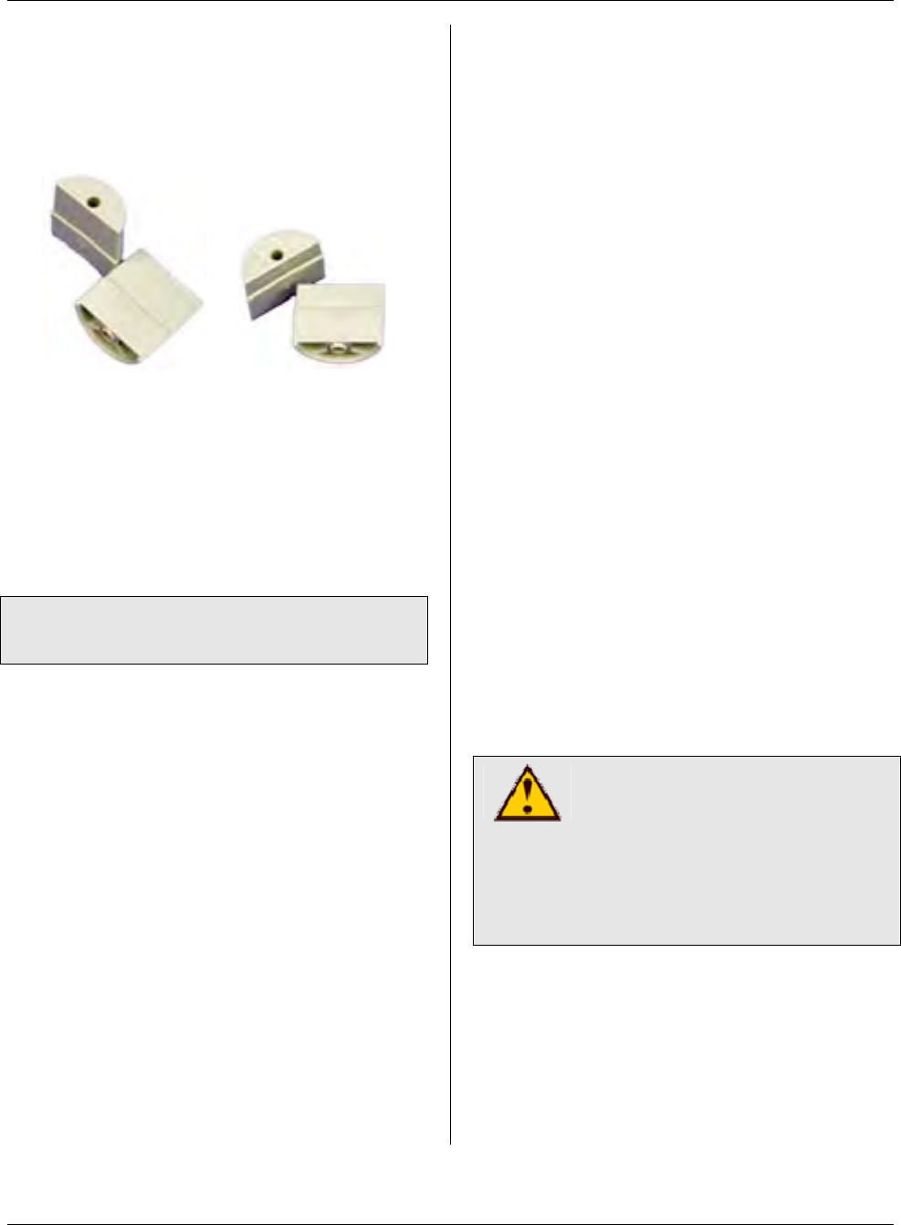
Note: Couplers are pre-assembled to the
MTU. Insure that the couplers are firmly
attached to the shaft and that the coupler
on the front side of the MTU contains the
magnet. Also, verify that the plastic
washer is in place between the rear
coupler and the MTU.
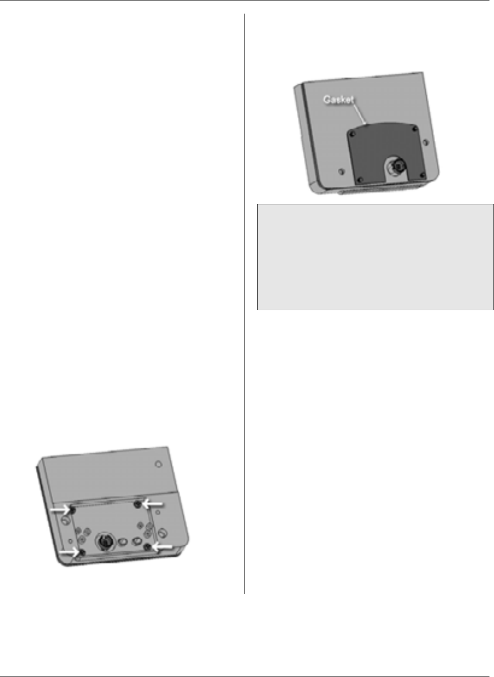
Step 5 - Position the MTU on the meter.
Rotate the coupler so that the gear tooth
on the coupler engages with the gear
teeth on the gas meter. Orientation is not
critical, but you should be able to feel the
teeth “bite” when you turn the coupler
from the front of the MTU.
Step 6 - Tighten the four 10-24 x 1-⅛”
screws to 12 to 15 in-lb. On a standard
drill driver with 0 to 24 torque settings,
this is typically the #10 setting. Tighten
corner to corner.
Step 7 - Check the coupler. It should
have slight play — it should not bind or
turn too freely.
Page 16
MTU Instruction
for Rockwell/Equimeter/Sensus Gas Meters
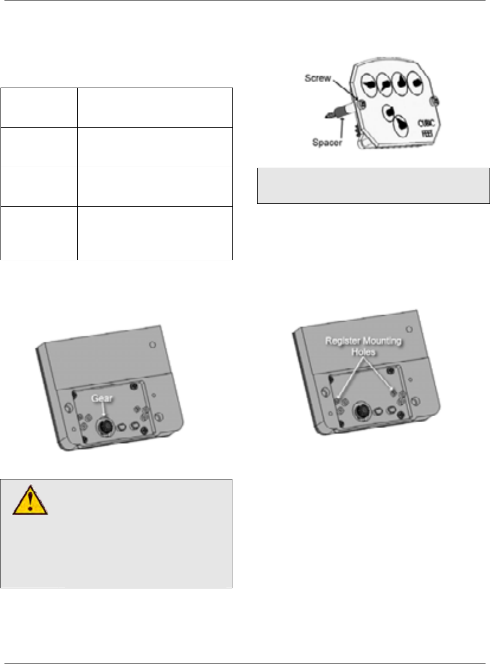
Step 8 – Select gear to fit between the
register and the MTU without binding.
Typically, the correct gear can be
selected based upon the type of index in
use, as shown in the following table.
Type of
Index Coupler Drive Gear
Plastic, dial-
type Blue Gear
(Part # 056-5155G4)
Brass, dial-
type Red Gear
(Part # 056-5155G3)
Plastic,
odometer-
type
Yellow Gear
(Part # 056-5155G2)
Place the selected gear into the coupling.
The head of the pin on the gear needs to
be facing out.
CAUTION!
Do not over tighten screws.
Excessive torque may
damage the MTU enclosure.
Power tools are not
recommended for use on
steps 9-12.
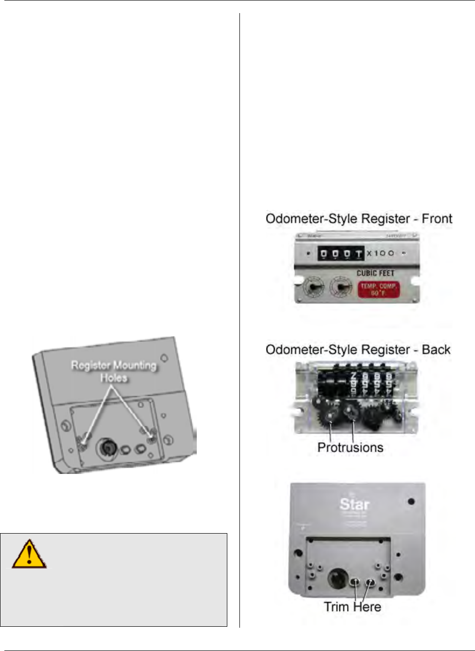
Step 9 - On the register, insert the screws
and spacers.
Note: Spacers may not be required with
odometer-style registers.
Step 10 - Mount the register to the MTU,
fastening it to the mounting holes shown
below. Hand tighten to a torque not to
exceed 3-5 inch-pounds. Make sure the
index register gear and the MTU coupler
gear are engaged.
Page 17
MTU Instruction
for Rockwell/Equimeter/Sensus Gas Meters
Step 11 - After you feel engagement
between the index register gear and the
MTU coupler gear, tighten the register
screws until they are snug.
Step 12 - Place the new cover over the
register so that the top label or arrow is
on top and the vent holes are on the
bottom. Align the cover with the mounting
holes on the MTU, press it into place, and
insert the #10 x 1” screws. Hand tighten
to a torque not to exceed 3-5 inch-
pounds. The gasket should be
compressed slightly.
Step 13 - Replace any anti-tamper,
safety, or security hardware onto the p-
lastic cover as required.
Step 14 – Once Installation is complete,
program the MTU using the STAR
Programmer Software and your MTU
Programmer.
Page 18

MTU Instruction
for Most Popular Water Meters
Purpose & Scope
This instruction provides wiring information for connecting STAR MTUs to any of the
following popular water meters:
• AMCO and/or ABB water meters (all sizes)
equipped with Invision, Scancoder, RS Pulser,
or Type A Industrial Pulser registers and with
the AMCO/ABB V100 (PSMT) meter and the
S130/5UM hot and cold water meters.
• Neptune and/or Schlumberger water meters (all
sizes) equipped with ARB-V, Auto/ProRead or
E-Coder PLUS registers.
• Sensus and/or Invensys water meters (all sizes)
equipped with ECR or ICE registers.
• Hersey water meters equipped with Translator
or ER2 registers.
• Badger water meters (all sizes) equipped with Read-O-Matic, RTR or ADE
registers.
• Metron water meters (all sizes) equipped with OER registers.
Supplies and Tools Required
See Publication 471-2000, General
Installation and Wiring Guidelines for a
complete list of recommended tools and
supplies for MTU Installation.
Installation Procedure
Step 1 - Select a mounting location for
the MTU that will allow optimum signal
transmission, and install any needed
wiring. Be sure to follow all General
Installation and Wiring Guidelines as
outlined in Publication 471-2000.
Step 2 – Select the wiring diagram that
applies to the meter you are connecting
and make the appropriate wiring
connections.
a. Direct Wiring to Meter - MTU
wiring is supplied stripped to a
standard length that fits water
meters with screw terminals.
Simply wrap the wires around the
screw terminal and tighten the
screw hand tight. Over tightening
the screw can stress and possibly
damage the wire.
b. Water Meter with Integral Cable -
If the water meter is supplied with
an integral cable and a cable-to-
cable splice is necessary, use a
gel-filled wire splice designed for
outdoor (moisture applications) to
seal the individual connections.
471-2002 - 7/24/2006
Page 19
MTU Instruction
for Most Popular Water Meters
Note: When connecting a dual port MTU
to a compound meter, connect port 1
(black jacket) to the primary, or high-flow
register and port 2 (grey jacket) to the
secondary or low-flow register.
Step 3 – Make a final visual check of the
wiring from the MTU to the meter register.
Verify that the cable routing is neat,
secure and professional.
Step 4 – Once installation and wiring are
complete, program the MTU using the
STAR Programmer Software and your
MTU Programmer.
Wiring Diagrams
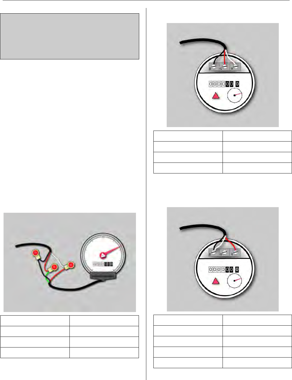
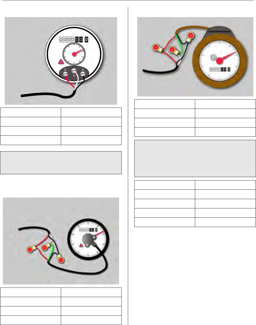
AMCO Invision
MTU Cable Invision Register
Red G (Green)
Black B (Black)
White R (Red)
AMCO/ABB Scancoder
MTU Cable Scancoder Register
Red G (Green)
Black B (Black)
White R (Red)
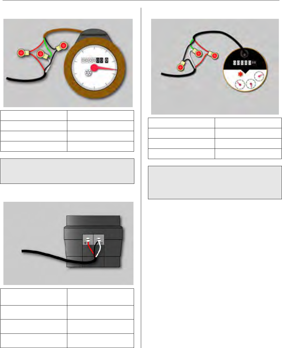
AMCO/ABB RS Pulser
MTU Cable RS Pulser Register
Red R (Red)
Black B (Black)
White B (Black)
No Connection G (Green)
Page 20
MTU Instruction
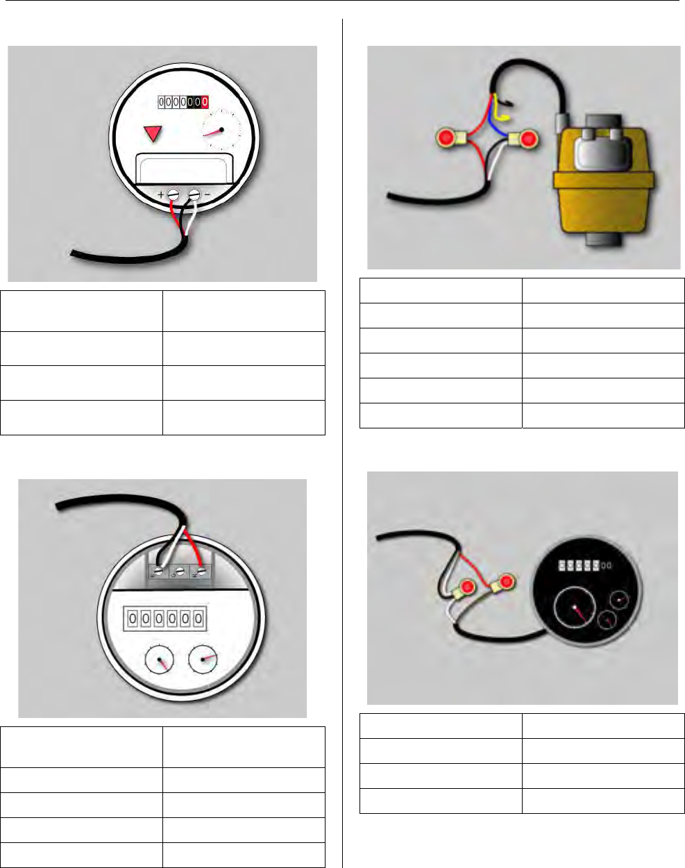
for Most Popular Water Meters
AMCO/ABB Type A Industrial Pulser
MTU Cable Type A Industrial
Pulser Register
Red + Positive
Black - Negative
White - Negative
AMCO Digital Register
MTU Cable AMCO Digital
Register
Red R (Red)
Black B (Black)
White B (Black)
No Connection G (Green)
AMCO/ABB V100 (PSMT)
MTU Cable V100 (PSMT) Cable
Red Red
Black Blue
White Blue
No Connection Black
No Connection Yellow
AMCO S130/5UM Hot Water
MTU Cable S130/5UM Cable
Red Brown
Black White
White White
Page 21
MTU Instruction
for Most Popular Water Meters
AMCO S130/5UM Cold Water
MTU Cable S130/5UM Cable
Red Brown
Black White
White White
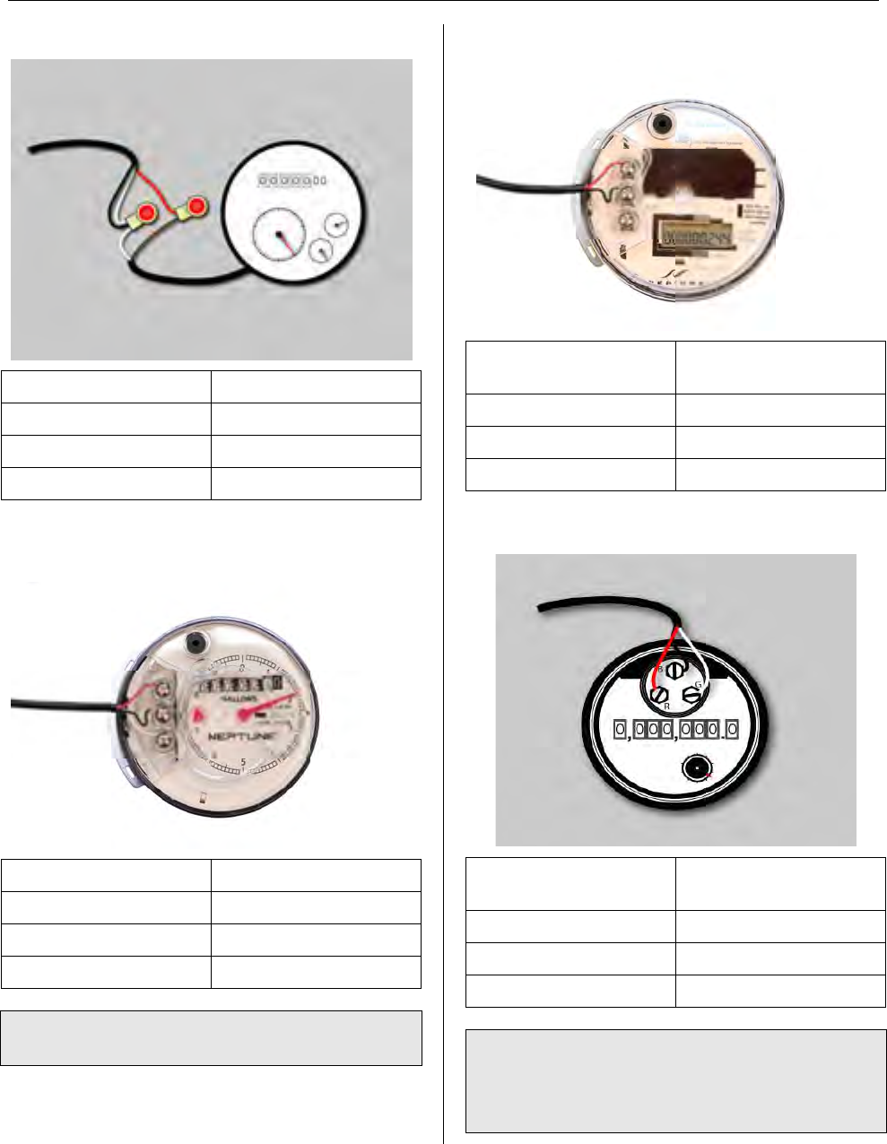
Neptune/Schlumberger ARB-V or
Auto/ProRead
MTU Cable ProRead Register
Red B (Black)
Black G (Green)
White R (Red)
Note: Auto/ProRead registers must be
programmed for 3-wire mode.
Neptune/Schlumberger E-Coder PLUS
MTU Cable E-Coder PLUS
Register
Red B (Black)
Black G (Green)
White R (Red)
Sensus/Invensys ECR or ICE
MTU Cable Sensus/Invensys
Register
Red R (Red)
Black B (Black)
White G (Green)
Note: The 8-digit Sensus ICE Register
must be programmed to deliver 6
consecutive digits of reading information
for proper operation with STAR MTUs.
Page 22
MTU Instruction
for Most Popular Water Meters
Hersey Translator
MTU Cable Hersey Register
Red R (Red)
Black B (Black)
White G (Green)
Note: The Hersey Translator Register
must be programmed for 6-digit readings
for proper operation with STAR MTUs.
Hersey ER2
MTU Cable ER2 Cable
Red R (Red)
Black B (Black)
White G (Green)
Badger RTR
MTU Cable RTR Cable
Red R (Red)
Black B (Black)
White G (Green)
Note: Some RTR registers may be
provided with only a black wire and a
white wire with a shield. For this
variation, Trim the shield off and connect
as listed below.
MTU Cable RTR Cable
Black B (Black)
White B (Black)
Red W (White)
No Connection White-Shield
Page 23
MTU Instruction
for Most Popular Water Meters
Badger ADE
MTU Cable ADE Cable
Red R (Red)
Black B (Black)
White G (Green)
Note: The Badger ADE register must be
programmed for 6-digit readings for
proper operation with a STAR MTU.
Badger Read-O-Matic
MTU Cable Read-O-Matic
Terminals
Red + Positive
Black - Negative
White - Negative
Metron OER Register
MTU Cable OER Cable
Red R (Red)
Black B (Black)
White G (Green)
Note: The 5-digit Metron OER register
must be configured for an additional
trailing zero for proper operation with
STAR MTUs.
Page 24

MTU Instruction
for American Meter Company Gas Meters
Purpose & Scope
This instruction provides a procedure for installing a STAR direct-mount MTU on the
following American Meter Company meters: AC-175, AL-175, AT-175, AC-250, AL-250,
AM-250, AR-250, AT-210/250, AT-350, AL-425, AC-630.
Parts Required
Ref. # Item Part Number Quantity
1 Gasket 066-5155E 1
2 Coupler, MTU 056-5155E1 2
3 Retaining Shaft, MTU 056-5155D 1
4 MTU, Direct Mount per project 1
5 Magnet 036-0002 1
6 #8 x 3/8” Combo Panhead Sheet Metal Screw 069-080012C4A 2
8 ¼-20 x 1 1/4” Slotted Fillister Head Machine Screw 069-142040GA 2
9 Register Cover 109-7712A 1
10 #10 x 1” Combo Panhead Sheet Metal Screw 069-100032C3A 2
471-2003 - 7/18/2007
Page 25
MTU Instruction
for American Meter Company Gas Meters
Tools Required
To mount the MTU to these meters, you
will need the following tools and
equipment:
• Safety glasses
• Phillips screwdriver
• Slotted screwdriver
Installation Procedure
Before installing the MTU, all anti-tamper,
safety, and security hardware must be
removed from the clear register cover.
Step 1 - Remove the existing clear
register cover by removing the four
screws that hold it. Discard both the
screws and the cover.
Step 2 - Remove the register by
removing the two screws that hold it. Set
the register aside. Discard the screws.
Step 3 - Mount the register onto the MTU,
fastening the register to the mounting
holes shown here with the #8 x 3/8”
screws provided.
Start one of the two screws into the
mounting hole, and then slide the register
beneath the screw aligning the wiggler on
the register with the MTU coupler.
CAUTION!
Do not over tighten screws.
Excessive torque may
damage the MTU enclosure.
Use of Power tools is not
recommended.
Then insert the second screw and tighten
both screws to a torque not to exceed 3-5
inch-pounds.
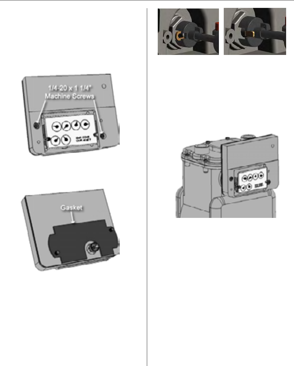
Note: On some odometer-style registers
like the one shown below, slight
protrusions on the back of the register
assembly can interfere with proper
alignment of the register. Should this
occur, use a diagonal cutting plier to trim
the two wire guides on the MTU to the
right of the coupler. Trim these guides as
close to flush with the MTU enclosure as
possible. (See MTU photo below.)
Page 26
MTU Instruction
for American Meter Company Gas Meters
Step 4 – Check that the register is
properly engaged by rotating the coupler
on the back of the MTU and observing
the register dials.
Step 5 – Next, Insert the two ¼-20 x 1
1/4” machine screws through the holes on
the MTU as shown here.
Step 6– Turn the MTU over and place the
gasket on the back of the MTU so that it
aligns over the two screws.
Step 7 – Next, position the MTU on the
meter. Tighten the two ¼-20 x 1 1/4”
mounting screws most of the way, and
then rotate the register dials slightly to
engage the wiggler on the gas meter. The
wiggler must engage with the rear coupler
on the MTU as shown in these
illustrations. (Coupler shown detached
from the MTU for illustration purposes
only.)
Half-foot Drive Quarter-foot Drive
Step 8 – Now, firmly hand tighten the two
screws to 12 to 15 in-lb. Be careful not to
over tighten the screws. Excessive torque
may damage the MTU enclosure.
Because of this, power tools are not
recommended for this procedure.
Step 9 - Check the coupling one more
time. It should have slight play — it
should not bind or turn too freely.
Step 10 - Place the new cover over the
register so that the top label or arrow is
on top and the vent holes are on the
bottom. Align the cover with the mounting
holes on the MTU, press it into place, and
insert the #10 x 1” screws. Hand tighten
to a torque not to exceed 3-5 inch-
pounds. The gasket should be
compressed slightly.
Page 27

MTU Instruction
for American Meter Company Gas Meters
Step 11 – Replace any anti-tamper,
safety, or security hardware onto the
plastic cover as required.
Step 12 – Once Installation is complete,
program the MTU using the STAR
Programmer Software and your MTU
Programmer.
Page 28

MTU Instruction
for American Meter Company Gas Meters
Purpose & Scope
This instruction provides a procedure for installing a STAR indirect-mount MTU on the
following American Meter Company meters: 5B-225, 225. Please also refer to
Publication 471-2000, General Installation and Wiring Guidelines for general information
covering the wiring and mounting of STAR MTUs.
Parts Required
Ref. # Item Part Number Quantity
1 Gasket Part of Item 4 1
2 Drive Foot Part of Item 4 1
3 Magnet Spyder Part of Item 4 1
4 American Meter 225 Sensor 109-7393B 1
5 Magnet 036-0002 1
6 #8 x 3/8” Combo Panhead Sheet Metal Screw 069-080012C4A 2
9 ¼-20 x 2” Slotted Fillister Head Machine Screw 069-142064HA 4
Not Shown MTU, Indirect Mount per project 1
Not Shown MTU spacer for pipe or bar mount 056-5155K 1
Not Shown 18″ heavy-duty UV-resistant tie wrap 067-0030 2
Not Shown 10-32 x 1½″ pan head machine screw 069-103248CS 2
Not Shown 10-32 nut, stainless steel 069-3011 2
Not Shown #10 7/16” flat washer, stainless steel 069-3004 2
471-2004 - 7/18/2007
Page 29
MTU Instruction
for American Meter Company Gas Meters
Tools Required
To mount the MTU to these meters, you
will need the following tools and
equipment:
• Cordless drill ⅜”, variable
speed, adjustable torque
settings
• #2 Phillips power screwdriver
bit
• Safety goggles
• Phillips screwdriver
• Slotted screwdriver
• 7/16″ nutdriver or boxwrench
• Diagonal side cutter
Installation Procedure
Installing the Sensor Assembly
Before installing the Sensor Assembly,
anti-tamper, safety, and security
hardware must be removed from the clear
register cover.
Step 1 - Remove the existing clear
register cover by removing the four
screws. Set the clear register cover aside.
Discard the screws.
Step 2 - Remove the register by
removing the two screws. Set the register
aside. Discard the screws.
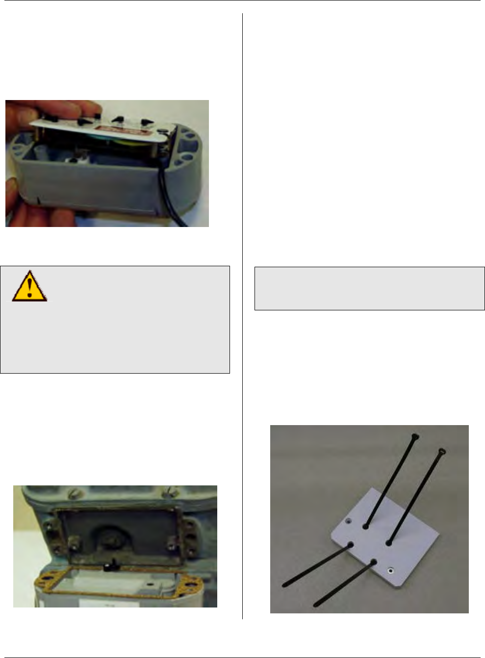
Step 3 - If the meter has a stamped metal
right angle drive foot (not a round plastic
pin), verify that the nylon spacer washers
are in place, as shown here.
Step 4 - If the meter has a stamped metal
right angle drive foot, orient the drive foot
of the index to the position of the magnet
coupler of the sensor as shown. The
index foot should be over the open or flat
area of the coupler. It should not engage
the elongated slot/hole in the magnet
coupler. When properly installed, the
magnet coupler will simply push on the
outside of the index foot to rotate it.
Page 2
Page 30
MTU Instruction
for American Meter Company Gas Meters
Step 5 - If the meter has a round plastic
pin, align the register to the American 225
Meter Adapter. The pin on the register
must be in the hole in the coupler, as
shown. Make sure the index foot rotates
freely.
Step 6 - Place the wire into the channel
to the right.
CAUTION!
Do not over tighten screws.
Excessive torque may
damage the MTU enclosure.
Power tools are not
recommended for use on
step 7.
Step 7 - Fasten the register to the
adapter with the two #8 x 3/8” screws
provided. Hand tighten to a torque not
to exceed 3-5 inch-pounds.
Step 8 - Rotate the adapter arm 180
degrees from the position of the meter
indexer. An example is shown.
Step 9 - Mount register with adapter and
the original plastic cover to the meter.
Step 10 - Attach the register and adapter
assembly to the meter with the four ¼-20
x 2 fillister head screws. Tighten the
screws to 12 to 15 in-lb. On a standard
drill driver with 0 to 24 torque settings,
this is typically the #10 setting.
Step 11 - Replace any anti-tamper,
safety, or security hardware onto the
cover as required.
Step 12 - Mount the MTU, following the
wiring and mounting guidelines outlined in
Publication 471-2000, General
Installation and Wiring Guidelines. If
necessary, the MTU cable can be
extended up to 500 feet.
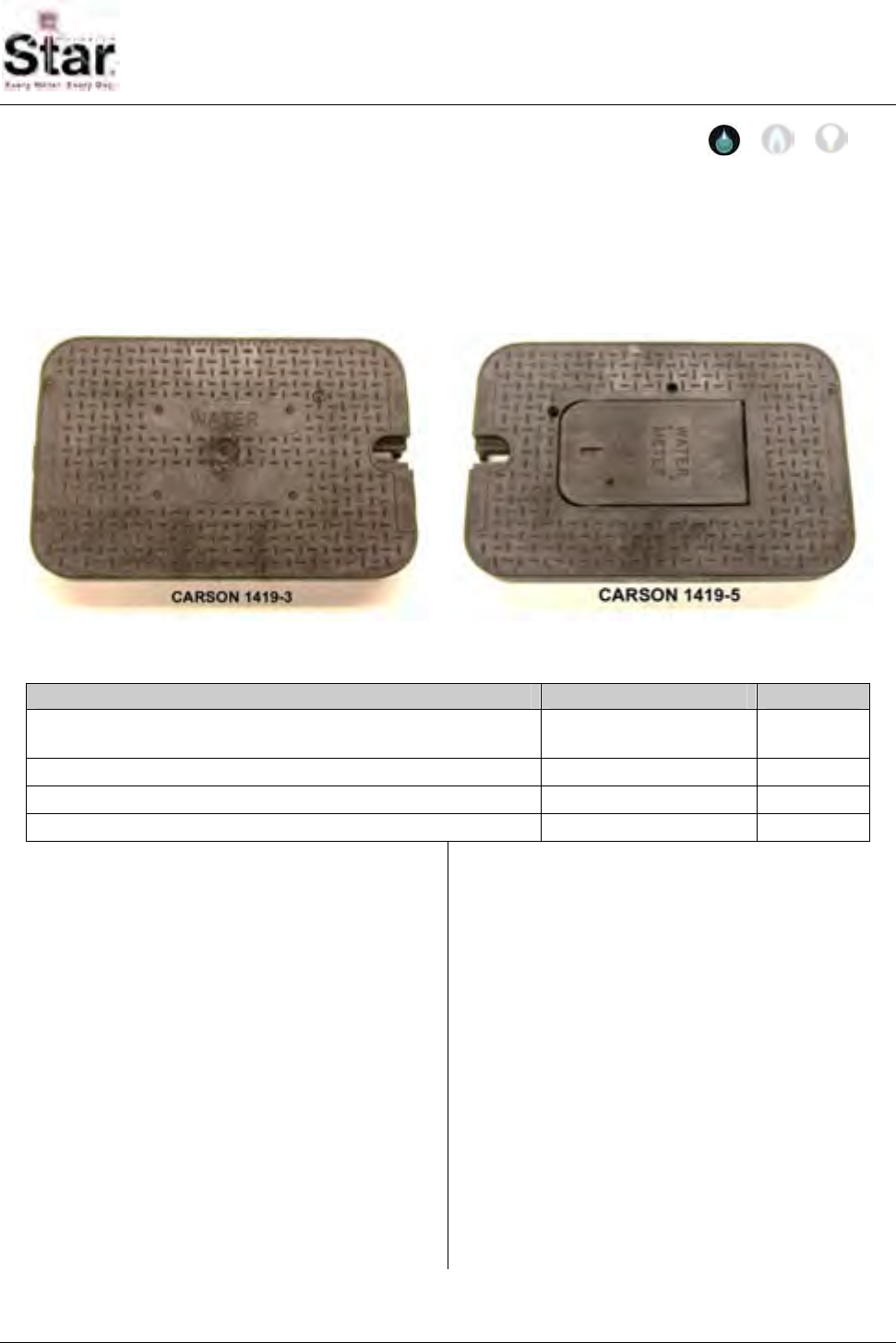
Note: If desired, you can mount the MTU
on the supply line using the bar-mounting
procedure below.
Step 13 – Once installation is complete,
program the MTU using the STAR
Programmer Software and your MTU
Programmer.
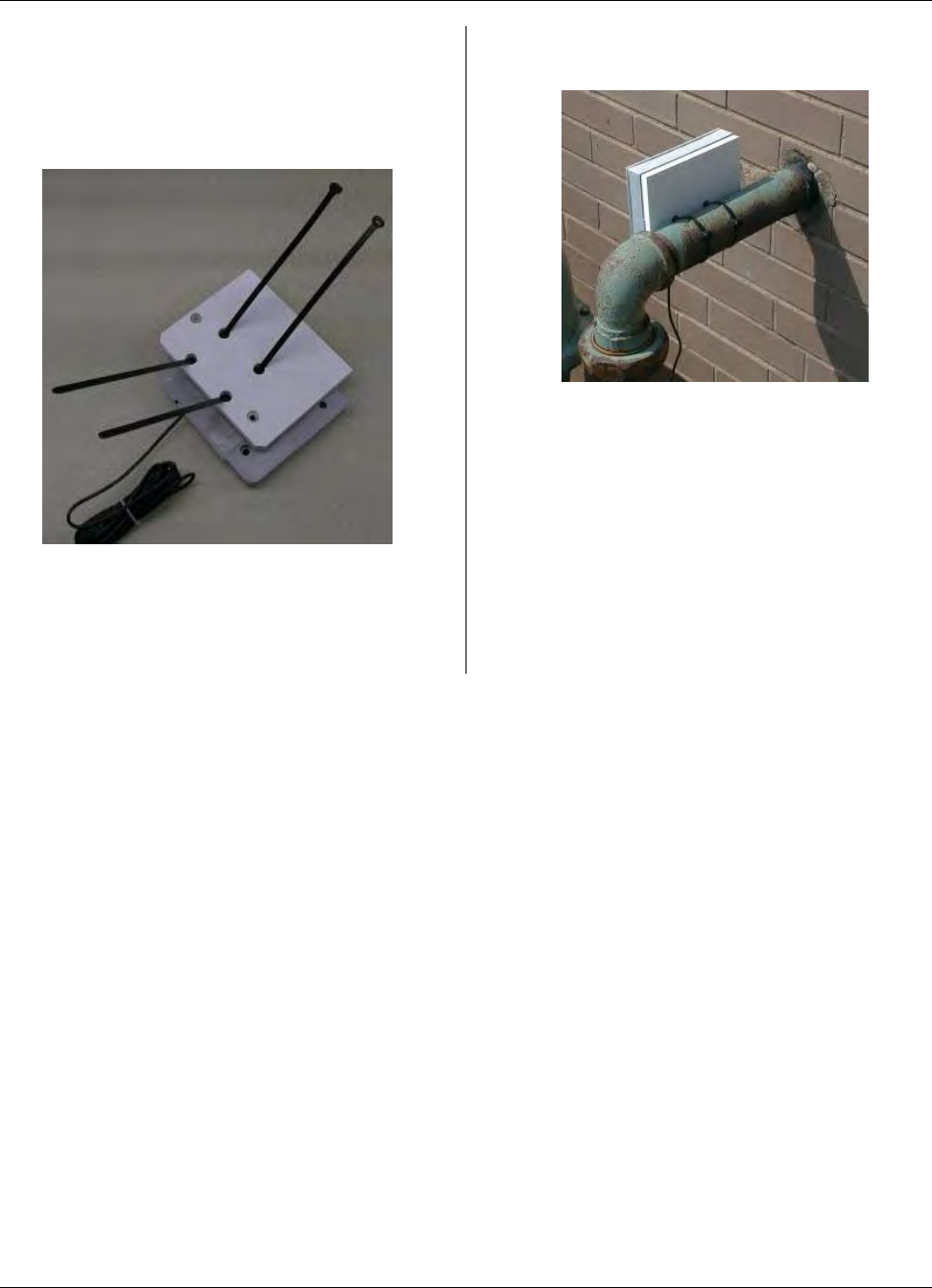
Bar-Mounting the MTU
Step 1 - Thread the tie-wraps into the
MTU spacer as shown here.
Page 31
MTU Instruction
for American Meter Company Gas Meters
Step 2 - Attach the spacer to the MTU
using the provided screws and washers.
Tighten the screws to 12 to 15 in-lb. On a
standard drill driver with 0 to 24 torque
settings, this is typically the #10 setting.
Step 3 - Wrap the tie wraps around the
bar as needed, pulling the ties around
(through the spacer plate) as they are
tightened.
Step 4 - Adjust the MTU as needed and
pull the tie wraps tight.
Step 5 - Trim off the excess tie wrap,
leaving about a ½” tab.
Step 6 – Once Installation is complete,
program the MTU using the STAR
Programmer Software and your MTU
Programmer.
Page 32
MTU Instruction
for Carson Industries 1419-3 and 1419-5 Pit Lids
Purpose & Scope
This instruction provides a procedure for mounting a STAR Flatpak MTU to a Carson
Industries Model 1419-3 or 1419-5 pit lid. This procedure does not detail the wiring of
the MTU to the meter that may be encountered inside of the pit. Please refer to
Publication 471-2000, General Installation and Wiring Guidelines in addition to any meter
specific MTU installation and programming instructions.
Parts Required
Item Part Number Quantity
MTU As required for
installed meter 1
¼” x 3 ½” Phillips flat-head stainless steel machine screw Source locally 2
¼’ Stainless Keps nut Source locally 2
¼” Stainless flat washer Source locally 2
Tools Required
To mount the MTU to these Carson pit
lids, you will need the following tools and
equipment:
• Drilling fixture for Model 1419
lids.
• Safety goggles
• #3 Phillips driver bit
• 7/16” Nut driver
• 17/64” standard drill bit
• MTU Programmer
• Cordless Drill 3/8”, variable speed,
with adjustable torque settings.
Note on setting the torque range: On a
drill-driver that has about 20 settings
(positions), set the adjustment to #6. Use
the lower speed range of the drill-driver.
This should amount to approximately 8 in-
lbs of torque. Reference the operating
instructions for your particular drill to
more accurately determine what setting to
use to achieve a torque range of
approximately 8 in-lbs.
471-2005 - 2/28/2006
Page 33
MTU Instruction
for Carson Industries 1419-3 and 1419-5 Pit Lids
Installation Procedure
Step 1 - Mount the drilling fixture onto
either model of the Carson Pit Lid. The
fixture is keyed so that it will align in only
one direction.
Step 2 - Hold the fixture secure in
position on the lid and drill two holes into
the lid using the supplied 17/64” drill bit,
through the guide holes in the fixture.
Step 3 - Remove the fixture from the lid.
Step 4 - Countersink the 2 holes using
the supplied ¾” 82 degree countersink,
only deep enough for the screw heads to
be flush or slightly below the surface of
the lid.
Step 5 - Insert 2 stainless screws through
the holes drilled in the top side of the lid.
Step 6 - Turn the lid over and attach the
FlatPak as shown below. Note the
FlatPak orientation. The front side (with
the STAR logo) must be placed against
the bottom of the lid. Apply a ¼” stainless
steel flat washer to each screw, then
apply the ¼-20 stainless steel keps nut to
each screw.
Step 7 - Tighten the hardware with the
torque driver. Use the nutdriver or
combination wrench to hold the nut if
necessary. Tighten hardware just past
snug.
CAUTION!
Use no more than 12-15 in-lbs
of torque. Do not over tighten
hardware.
Page 34
MTU Instruction
for Carson Industries 1419-3 and 1419-5 Pit Lids
Step 8 - Turn the lid over and verify that
the heads of the screws are flush or
below the lid surface.
CAUTION!
Be sure to follow all General
Guidelines outlined in
Publication 471-2000 along
with the specific wiring
instructions for the meter
being used.
Step 9 – Wire the MTU to the meter,
folding and forming wires into valve box
as necessary so that they do not interfere
with lid locking mechanism and cannot
become pinched.
Step 10 - Installation is now complete.
You can now proceed to program the
MTU using the STAR Programmer
Software and your MTU Programmer.
Page 35

MTU Instruction
for Carson Industries 1419-3 and 1419-5 Pit Lids
Intentionally Left Blank
Page 36
MTU Instruction
for Armor Access Rubber Pit Lids
Purpose & Scope
This instruction provides a procedure for mounting a STAR Flatpak MTU to an Armor
Access brand rubber composite pit lid. This procedure covers the mounting of an
Original Flatpak STAR MTU or the New Flatpak STAR MTU to these pit lids. This
procedure does not detail the wiring of the MTU to the meter that may be encountered
inside of the pit. Please refer to Publication 471-2000, General Installation and Wiring
Guidelines in addition to any meter specific MTU installation and programming instructions.
Parts Required
Item Part Number Quantity
MTU As required for installed
meter 1
Long Spacers (for pit lid mounting of New Style Flatpak
MTUs) 056-8150L 2 per New
Style MTU
installation
#10 x 2 1/2” Phillips Pan Head Type AB Stainless Steel
Sheet Metal Screw 2 per New
Style MTU
installation
#10 x 2” Phillips Truss Head Type AB Stainless Steel
Sheet Metal Screw 2 per Original
Style MTU
installation
Tools Required
To mount the MTU to these Armor
Access pit lids, you will need the following
tools and equipment:
• Safety goggles
• #3 Phillips driver bit
• Cordless Drill 3/8”, variable speed,
with adjustable torque settings.
Note on setting the torque range: On a
drill-driver that has about 20 settings
(positions), set the adjustment to #6. Use
the lower speed range of the drill-driver.
This should amount to approximately 8 in-
lbs of torque. Reference the operating
instructions for your particular drill to
more accurately determine what setting to
use to achieve a torque range of
approximately 8 in-lbs.
471-2006 - 11/6/2006
Page 37
MTU Instruction
for Armor Access Rubber Pit Lids
Installation Procedure
Mounting an Original Flatpak STAR
MTU to an Armor Access pit lid.
Step 1 – If there is a recess on the
bottom surface of the pit lid, place the
MTU into the recess. If no recess, center
the MTU as shown onto the inside
surface of the lid.
Pit Lid with No Recess
Pit Lid with Recess
Step 2 - Attach the MTU to the pit lid with
the 2” stainless sheet metal screws
through the recessed mounting holes as
shown. Torque screws to approximately 8
in-lbs. MTU should be snug and flush to
the surface of the pit lid.
Pit Lid with No Recess
Pit Lid with Recess
Step 3 – Wire the MTU to the meter,
making sure that the wire is routed so that
it does not become pinched when the lid
is closed.
Step 4 - Installation is now complete. You
can now proceed to program the MTU
using the STAR Programmer Software
and your MTU Programmer.
CAUTION!
Be sure to follow all General
Guidelines outlined in
Publication 471-2000 along
with the specific wiring
instructions for the meter
being used.
Page 38
MTU Instruction
for Armor Access Rubber Pit Lids
Mounting a New Flatpak STAR MTU to
an Armor Access pit lid.
Step 1 – Center the MTU as shown onto
the bottom surface of the pit lid. Place
plastic spacers under the mounting lugs
on the MTU as shown below. Be sure to
use the long spacers (Hexagram Part
Number 056-8150L).
Step 2 - Attach the MTU to the pit lid with
the 2 ½” stainless sheet metal screws
through the 2 mounting holes and the
spacers as shown. Torque screws to
approximately 8 in-lbs. The MTU should
be snug and suspended by the spacers
above the bottom surface of the pit lid by
approximately ½”.
Step 3 – Wire the MTU to the meter,
making sure that the wire is routed so that
it does not become pinched when the lid
is closed.
Step 4 - Installation is now complete. You
can now proceed to program the MTU
using the STAR Programmer Software
and your MTU Programmer.
Page 3
Page 39

MTU Instruction
for Armor Access Rubber Pit Lids
Intentionally Left Blank
Page 40
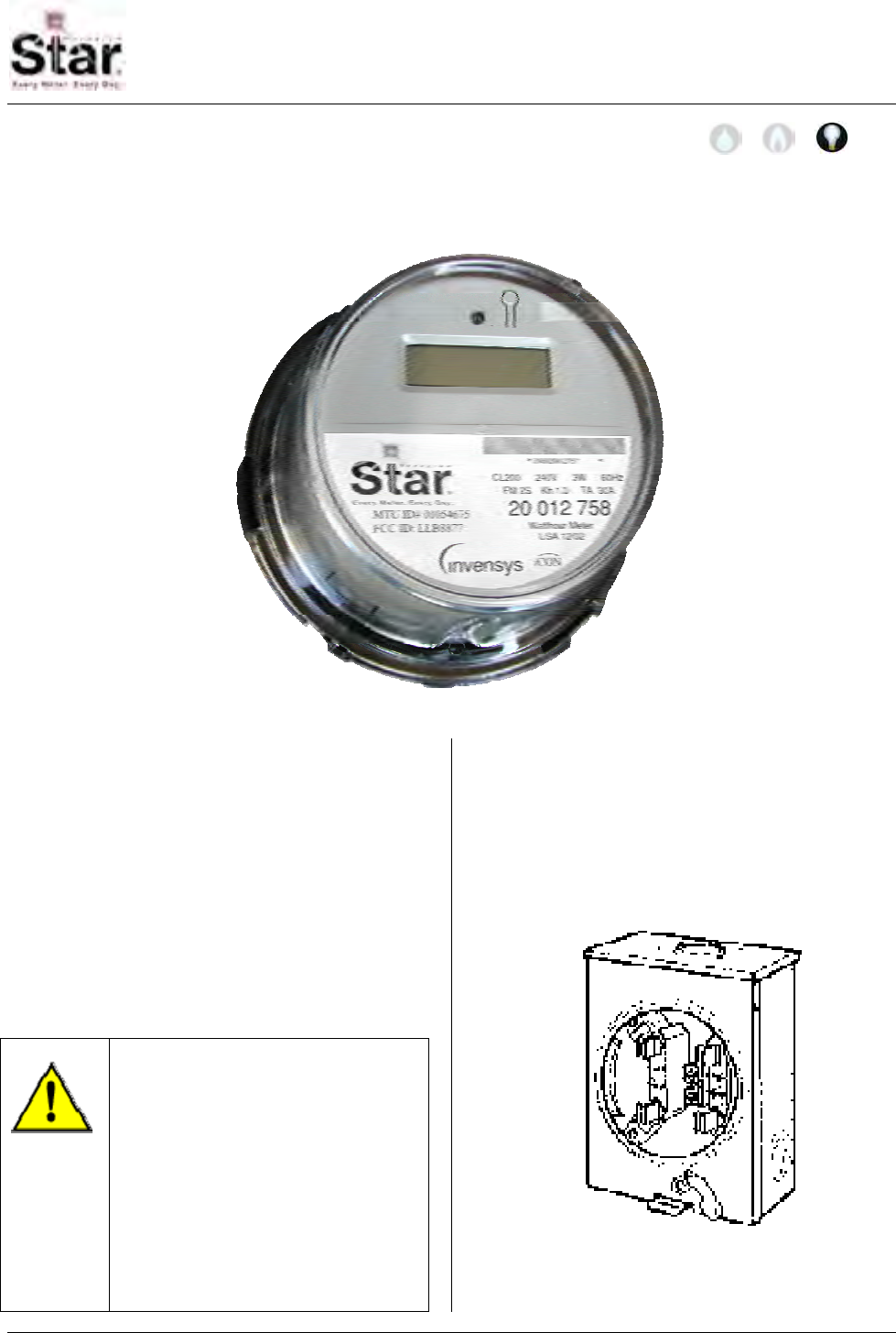
MTU Instruction
for Invensys Icon MTU/Electric Meter Assembly
Purpose & Scope
This instruction provides a procedure for installing FORM 2s and FORM 12S Invensys
Icon MTU/Electric Meter Assemblies.
Supplies and Tools Required
Physical Installation of the ICON Form 2S
and Form 12S MTU/Electric Meter
Assemblies into compatible meter
sockets can be accomplished without the
use of tools.
Testing of the meter socket, however,
may require specialized equipment.
Check with the local electric utility for
required testing procedures.
WARNING!
Be sure to follow all local
safety procedures and do not
touch the exposed electrical
terminals in the meter socket.
These terminals carry the full
incoming service voltage.
Touching these terminals may
result in death or serious
injury.
Installation Procedure
Step 1 – Complete all test procedures
required by the local electric utility and
verify that the meter socket has been
correctly installed and wired.
471-2007 - 2/28/2006
Page 41
MTU Instruction
for Invensys Icon MTU/Electric Meter Assembly
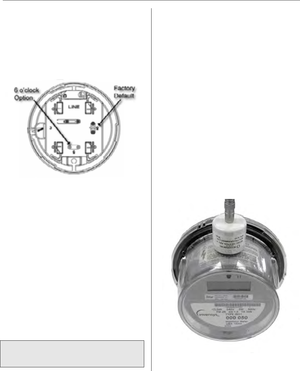
Step 2 – (For Form 12S meters only –
Skip this step for Form 2S meters) The
neutral-blade of the Form 12S meter can
be moved. The figure below shows the
rear of the meter base with the neutral-
blade in the factory default, 9 o’clock
position (referenced by looking into the
meter socket.)
The neutral-blade can be moved to the 6
o’clock or 3 o’clock position to fit varying
Form 12S meter sockets using a #1
Phillips screwdriver, as follows:
a. Locate the configurable neutral-
blade – On the rear of the meter
base, locate the configurable
neutral-blade.
b. Remove screws – Remove the
two screws on either side of the
neutral-blade.
c. Remove neutral-blade – Remove
the neutral-blade from its molded
socket.
d. Seat neutral-blade – Seat the
neutral-blade into the desired
location.
Note: When replacing the screws, ensure
that they are snug, and that the heads are
flush with the neutral-blade.
e. Replace screws – Place the two
screws in the new neutral-blade
location.
Step 3 – Place the meter/MTU assembly
into the meter socket, carefully aligning
the contact blades with the corresponding
jaws in the meter base.
Step 4 – Install a T-bar and /or any seals
necessary to meet local requirements.
Step 5 – Make a final visual inspection to
ensure that the meter/MTU assembly is
seated and sealed properly.
Step 6 – Installation is now complete,
program the MTU using the STAR
Programmer Software and your MTU
Programmer.
When programming the integral MTU
mounted in this meter, hold the
programming coil above the top center of
the meter, as shown here.
Page 42
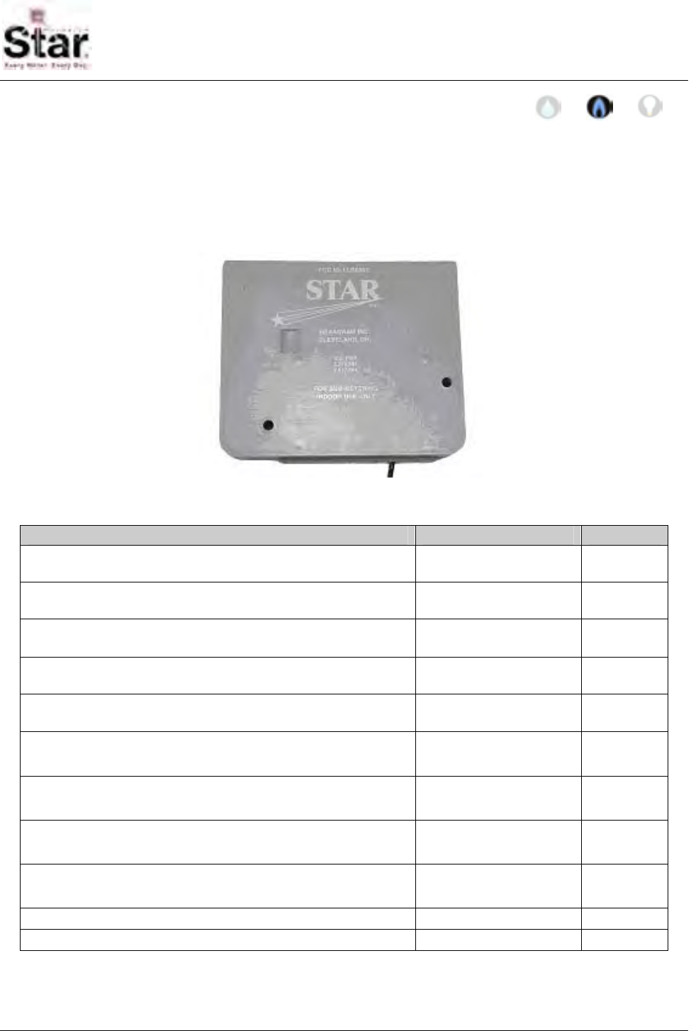
MTU Instruction
for STAR Submetering MTUs with Pulse Adapters
Purpose & Scope
This instruction provides procedures for installing and programmin STAR MTUs equipped
with voltage or temperature sensing pulse adapters including the following: 501-7786P,
501-7786T, 501-7786-PP, 501-7786PR, 501-7786PT, 501-7786PT2. Please also refer to
Publication 471-2000, General Installation and Wiring Guidelines for general information
covering the wiring and mounting of STAR MTUs.
Parts Required
Item Part Number Quantity
Submetering MTU with temperature sensing pulse adapter. 501-7786T 1
(As required)
Submetering MTU with voltage sensing pulse adapter. 501-7786P 1
(As required)
Dual-port Submetering MTU with voltage sensing pulse
adapters. 501-7786PP 1
(As required)
Dual-port Submetering MTU with a voltage sensing pulse
adapter and a reed switch input. 501-7786-PR 1
(As required)
Dual-port Submetering MTU with voltage and temperature
sensing pulse adapters. 501-7786-PT 1
(As required)
Thermocouple, Type E, 20 gauge 071-0850 1 per
temperature
sensing port.
Wire Splice, 3M Scotchlok 314 043-1914 2 per
temperature
sensing port.
Cable Tie, 5.6”, Black, UV 067-0007 3 per
temperature
sensing port.
Pressure Sensitive Hold-downs 067-0051 2 per
temperature
sensing port.
Drywall screws, #6 x 2” Phillips, coarse (for indoor use) Source locally 2 per MTU
Plastic masonry anchors #6 – 12 x 1”, ¼” diameter Source locally 2 per MTU
471-2008 - 2/22/2008
Page 43

MTU Instruction
for STAR Submetering MTUs with Pulse Adapters
Tools Required
• Crimping Pliers for Insulation
Displacement Connectors (IDCs)
• Wire cutters/stripper
• Cleaner (non-residue type) and
rag/paper towel
• Stapler for ¼” wire and cable
(Arrow T-25M)
Introduction
STAR Submetering MTUs with Pulse
Adapters provide accurate, high-
resolution data for point-of-use allocation
billing for a wide variety of HVAC
appliances.
Note: Only on-off devices are suitable for
application of these pulse adapter MTUs.
• Voltage Sensing Pulse
Adapters can be applied to
gas appliances that are
controlled by a standard
24VAC gas valve.
• Temperature Sensing Pulse
Adapters can be applied to
gas water heaters, fireplaces
and other HVAC appliances
that do not have 24 VAC
controls
These units produce an extremely
accurate pulse at a rate of 10 seconds
per pulse (0.1 Hz or 6 pulses per minute)
when the specified input conditions
(voltage or temperature) are met. These
pulses are counted by the MTU which
periodically transmits the accumulated
count to nearby Data Collector Units.
Note: The submetering MTUs discussed
in this instruction are for indoor use (dry
locations) only.
Connecting Voltage Sensing
(Type P) Inputs
Voltage Sensing (Type P) inputs are
provided with a 2-wire connection that
can be wired across (in parallel with) the
24 VAC gas valve solenoid of the furnace
or other HVAC appliance.
Simply connect the RED and BLACK
wires across the gas valve solenoid.
Once connected in this way, a voltage of
between 18 and 30 VAC applied across
the valve solenoid will cause the MTU to
begin pulsing and recording usage.
CAUTION
Do not connect the white wire
of the MTU when connecting
voltage sensing inputs. Cut
the white wire back to the
cable jacket. Connecting the
white wire may damage the
MTU.
Typical Furnace Application
This procedure covers a typical
installation of a voltage/current sensing
pulse adapter on a gas furnace.
Step 1 - Turn the furnace setting to "Pilot"
so that it will not operate during the
installation process.
Step 2 - Mount the MTU on a wall, joist or
other convenient location near the
furnace to be monitored. Run the cable
from the MTU to the gas valve solenoid of
the device. Trim or extend the MTU
cable, as needed. Care must be taken to
protect the cable from damage by hot
surfaces or sharp sheet metal. Use
insulated staples or cable ties as needed.
Note: Be sure to follow all General
Mounting & Wiring Guidelines outlined in
Publication 471-2000.
Page 44
MTU Instruction
for STAR Submetering MTUs with Pulse Adapters
Step 3 – Connect the RED and BLACK
leads from the MTU across (in parallel
with) the 24 VAC control input to the gas
valve. On most gas valves, these
connections can be made at the terminals
on the gas valve solenoid.
● The VIOLET lead is the positive
side and must be connected to the
RED wire of the MTU Input Cable.
● The RED lead of the thermocouple
is the negative side and must be
connected to the BLACK wire of
the MTU input cable.
Step 4 – Program the MTU using the
MTU Programmer as outlined in the
Programming section of this document. Typical Hot Water Heater
Application
Step 5 - Return the furnace setting to
"Run". This procedure covers a typical
installation of a temperature sensing
pulse adapter on a gas hot water heater.
Connecting Temperature
Sensing (Type T) Inputs Step 1 - Turn the hot water heater setting
to "Pilot" so that the heater will not
operate during the installation process.
Temperature Sensing (Type T) inputs are
provided with a two wire connection
designed to be directly connected to a
Type E thermocouple that is supplied with
the temperature sensing MTU. When the
thermocouple reaches a temperature of
110◦ - 130◦ C (230◦ - 265◦ F), the MTU will
begin pulsing and recording usage.
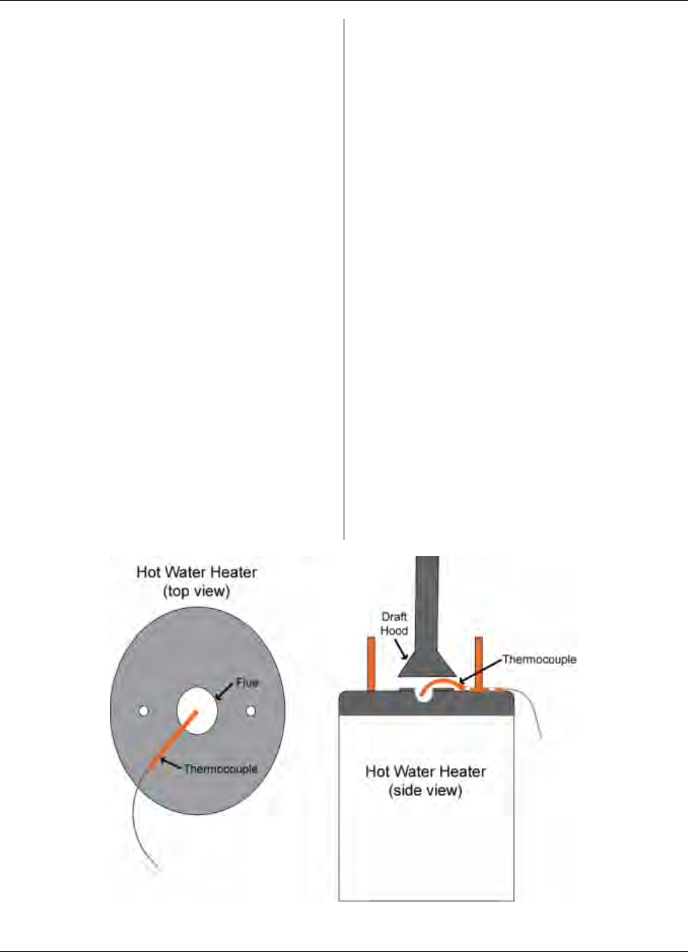
Step 2 - Insert the copper thermocouple
sleeve into the space under the draft-
inducer cone at the top of the water
heater. Position the tip of the
thermocouple INTO the center of the flue
as shown below. ( ½ to ¾ of an inch)
By convention, Type E thermocouples are
supplied with two color-coded leads.
Page 45

MTU Instruction
for STAR Submetering MTUs with Pulse Adapters
Gently shape the copper sleeve on the
thermocouple so that it does not contact
the metal surface of the draft hood or the
top of the hot water tank as shown in the
side view illustration.
Step 3 - Clean the surface area of the hot
water heater under the thermocouple.
Dry thoroughly. Locate and mount the
two pressure sensitive hold-downs in the
cleaned area. Locate one hold-down at
the approximate center of the copper
sleeve and the other at the very end so
that they firmly anchor the thermocouple.
Thread a cable tie through the slot in the
hold-downs to fasten the thermocouple.
If necessary, gently form the copper
sleeve to facilitate mounting while
insuring that the tip of the thermocouple is
in the center of the flue and the copper
sleeve is not in contact with metal
surfaces.
Step 4 - After the thermocouple sleeve is
secure, route the thermocouple wire near
the inlet or outlet water pipe. Use the
third cable tie to secure the thermocouple
wire to the pipe as a strain relief.
Step 5 - Mount the MTU on a wall, joist or
other convenient mounting location using
two screws. Run the cable from the MTU
to the end of the thermocouple wire. Trim
excess MTU cable, as needed. Care
must be taken to protect the cable from
damage by hot surfaces or sharp sheet
metal. Use insulated staples or cable ties
as needed.
Note: Be sure to follow all General
Mounting & Wiring Guidelines outlined in
Publication 471-2000.
Step 6 - Splice the MTU wire to the
thermocouple wire using the two IDCs
provided.
● Connect the VIOLET
thermocouple wire to the RED
MTU wire.
● Connect the RED thermocouple
wire to the BLACK MTU wire.
Do not remove the insulation from either
the MTU wires or the thermocouple wires;
the IDC is designed to pierce the
insulation.
Step 7 – Program the MTU using the
MTU Programmer as outlined in the
Programming section of this document.
Step 8 - Return the hot water heater
setting to "Run".
Typical Burner/Fireplace
Application
This procedure covers a typical
installation of a temperature sensing
pulse adapter on a burner or fireplace.
Step 1 - Set burner or fireplace control so
that the appliance does not come on
during installation.
Step 2 - Fasten thermocouple so that the
tip is near, but not in, the flame when the
gas is burning. Use metal clamps or wire
fasteners to secure the thermocouple.
(NOTE: Clamps or wire fasteners are not
provided by Hexagram. Individual
installation conditions will determine the
type of fastener to be used.) A location
must be selected that allows the
thermocouple tip to reach at least 130° C
(400° F). However, the tip temperature
must not exceed 350° C (660° F). If a
pilot light is present, keep the
thermocouple at least 6" away from the
pilot flame.
Step 3 - Route thermocouple wire away
from the appliance.
Page 46

MTU Instruction
for STAR Submetering MTUs with Pulse Adapters
Step 4 - Mount the MTU on a wall, joist or
other convenient mounting location well
away from the heat source using two
screws.
CAUTION
The MTU must be located
away from the appliance and
ONLY in a location that
remains at room temperature.
Run the cable from the MTU to the end of
the thermocouple wire. Trim excess MTU
cable, as needed. Care must be taken to
protect the cable from damage by hot
surfaces or sharp sheet metal. Use
insulated staples or cable ties as needed.
Note: Be sure to follow all General
Mounting & Wiring Guidelines outlined in
Publication 471-2000.
Step 5 - Splice the MTU wire to the
thermocouple wire using the IDCs
provided. Use a cable tie(s) to provide
strain relief for the wiring.
● Connect the VIOLET
thermocouple wire to the RED
MTU wire.
● Connect the RED thermocouple
wire to the BLACK MTU wire.
Do not remove the insulation from either
the MTU wires or the thermocouple wires;
the IDC is designed to pierce the
insulation.
Step 6 - Secure the MTU wire. Verify
that the MTU cable does not run near the
burner and does not enter any region
where the temperature will exceed 70° C
(160° F).
Step 7 – Program the MTU using the
MTU Programmer as outlined in the
Programming section of this document.
Step 8 - Reset the burner or fireplace
control so that the appliance can run.
Programming
Note: The 501-7786PT2 MTU requires
Star Programmer Software version 6.0.0
and meter table version 3.85 or higher.
Step 1 - Turn on the Psion MTU
Programmer by pushing On/Esc.
Step 2 - Highlight the STAR icon (in the
Psion desktop screen) using the left/right
arrow keys. Press Enter.
At this point, the STAR software loads
along with the Meter table, Database
table, and Appointment table. If these are
loading for the first time, it may take
several minutes. When complete, the
serial number verification screen will
appear.
Note: A “Communication Error”
message may occur:
● If an attempt is made to read
and/or program the MTU and the
MTU is receiving input from the
gas appliance to which it is
wired.
OR
● If an attempt is made to read
and/or program the MTU and
there is a wiring error in the
wiring between the MTU and the
thermocouple.
Verify that the gas appliance is off and
that the thermocouple is correctly
connected.
Page 47
MTU Instruction
for STAR Submetering MTUs with Pulse Adapters
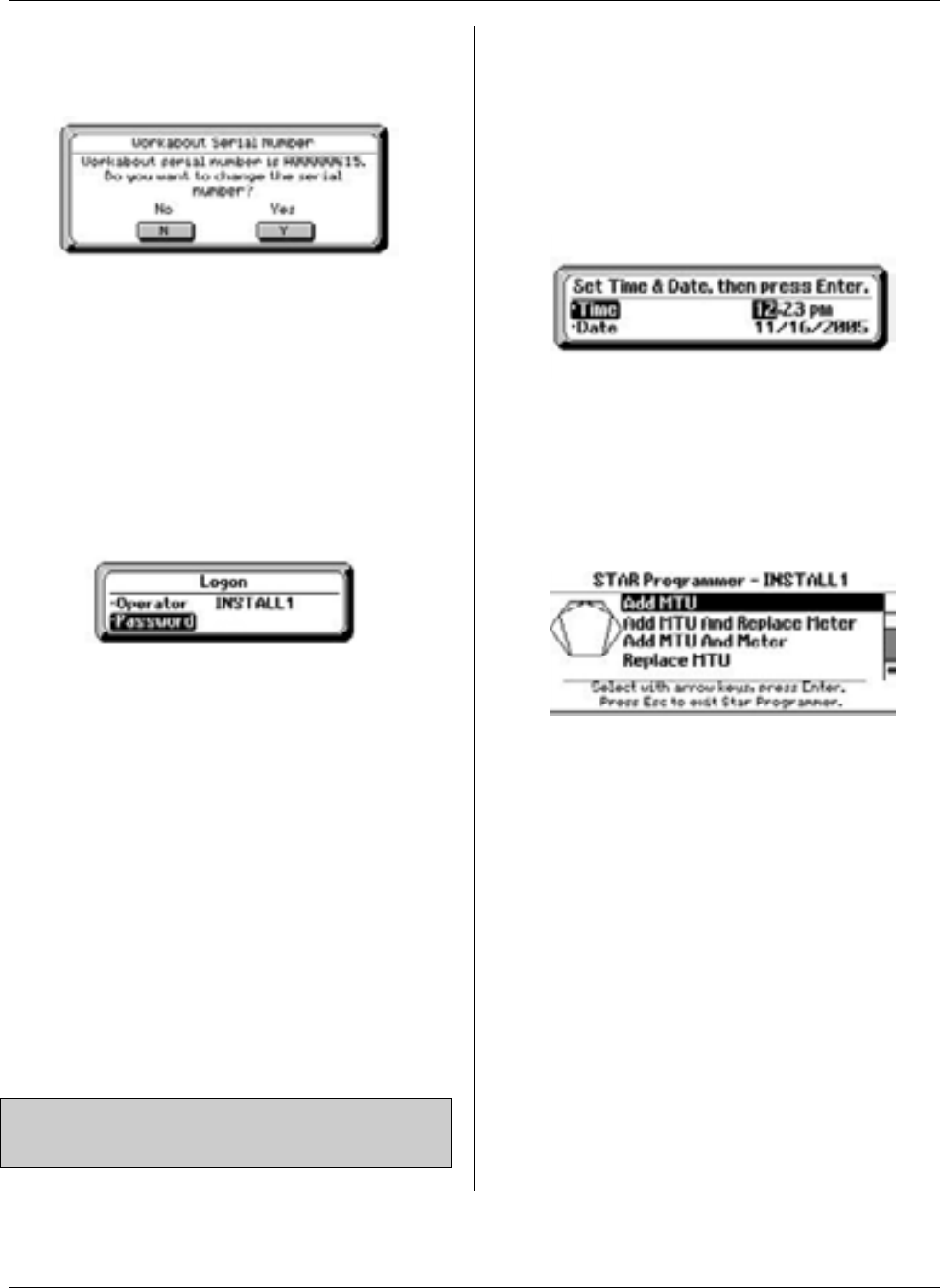
Step 3 - A screen asking if the operator
wishes to change the Psion’s serial
number is displayed.
NOTE: - At midnight, the software
automatically resets to require re-entry of
the log-on information. This is a security
measure in case the Psion is lost or
stolen.
Step 5 - The “Set Time & Date” screen is
displayed.
This number should match the last four
digits of the serial number etched on the
back of the Psion. Typically, select N to
accept the serial number as is. Pressing Y
will take the operator to a screen where
the serial number can be changed, if
necessary.
Step 4 – You are now at the logon
screen.
Log on by entering the following
information:
a - Operator: The Psion operator file
will accommodate up to 99 separate
operator user codes. This user code is
“Install” followed by an assigned
operator code. Enter your assigned
code number immediately after “Install”
without any spaces. Press Enter when
finished. Example: Install6
b - Enter the password. This password
will typically be assigned by a project
manager. Press Enter when finished.
Example: Acme
Note: Use the DEL key to backspace and
make corrections.
Make any corrections to the time and
date as required. Press Enter when
finished. It is not necessary to reset the
time if it is less than 5 minutes off.
Step 6 - The main menu of the STAR
software is now displayed.
At the top of the screen the installer
identification is displayed. The bottom of
the screen has instructions for navigation.
Most of the screens in the STAR software
have this instruction feature at the bottom
of the screen. The menu consists of
options you can select, as described in
the following table. The actual options
you see will depend on the configuration
of your system. Some choices may not
be available on your system.
Page 48

MTU Instruction
for STAR Submetering MTUs with Pulse Adapters
STAR Programming Software – Main Menu Choices
Menu Item Function
Add MTU Select this item when a new MTU is being connected to an existing meter.
Add MTU And Replace
Meter Select this item when a new MTU is being added and the current meter is being
replaced.
Add MTU And Meter Select this item when a new MTU and meter are being installed where no
previous equipment existed.
Replace MTU Select this when an existing MTU is being replaced and no meter changes are
occurring.
Replace Meter Select this when an existing meter is being replaced and no MTU changes are
occurring.
Replace MTU And
Meter Select this when an existing MTU and meter are being replaced.
Reprogram MTU Use this selection when reprogramming an MTU with no equipment changes.
Read MTU Select this to read the current configuration information from an MTU.
Turn MTU Off Select this to turn an MTU off, causing its transmissions to stop.
Operator log-off To log off the STAR Programmer software, select this option and press Enter.
About STAR
Programmer Choose this menu option if you need to contact a customer service representative
at Hexagram.
To select the desired programming mode,
use the up/down arrow keys to scroll to
the mode on the STAR program Main
Menu screen and press Enter. Follow the
instructions on the screen and enter the
requested data. At any time before
installation data is actually written to the
MTU, the operator can cancel out of the
programming operation by pressing
On/Esc. The operator will be required to
enter a reason as to why programming
was cancelled.
Once programming has been
successfully completed, the MTU will be
turned on and will Start transmitting its
wake up data to the DCU every five
minutes. It will transmit for less than a
second of every five minutes for forty-five
minutes.
Page 49

MTU Instruction
for STAR Submetering MTUs with Pulse Adapters
Intentionally Left Blank
Page 50
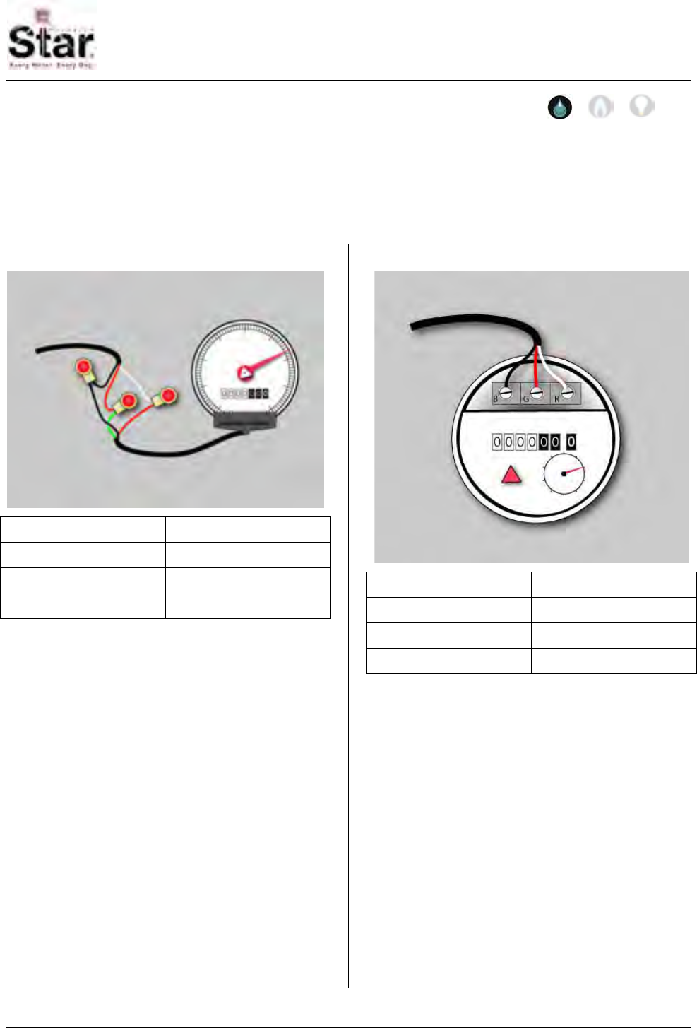
MTU Instruction
for AMCO and ABB Water Meters
Purpose & Scope
This instruction provides wiring information for use in connecting a STAR MTU to AMCO
and/or ABB water meters (all sizes) equipped with Invision, Scancoder, RS Pulser, Type
A Industrial Pulser, or AMCO Digital registers and with the AMCO/ABB V100/PSMT
meter, and the S130/5UM hot and cold water meters.
Invision
MTU Cable Invision Register
Red G (Green)
Black B (Black)
White R (Red)
Scancoder
MTU Cable Scancoder Register
Red G (Green)
Black B (Black)
White R (Red)
Supplies and Tools Required
See Publication 471-2000, General
Installation and Wiring Guidelines for a
complete list of recommended tools and
supplies for MTU Installation.
Installation Procedure
Step 1 - Select a mounting location for
the MTU that will allow optimum signal
transmission, and install any needed
wiring. Be sure to follow all General
Installation and Wiring Guidelines as
outlined in Publication 471-2000.
Step 2 – Select the wiring diagram that
applies to the meter you are connecting
and make the appropriate wiring
connections.
a. Direct Wiring to Meter - MTU wiring
is supplied stripped to a standard
length that fits water meters with
screw terminals. Simply wrap the
wires around the screw terminal and
tighten the screw. It is recommended
that the screws be tightened to no
more than 4 – 5 in-lbs. Overtightening
the screw can stress and possibly
fracture the wire.
471-2009 - 2/28/2006
Page 51

MTU Instruction
for AMCO and ABB Water Meters
b. Water Meter with Integral Cable - If
the water meter is supplied with an
integral cable and a cable-to-cable
splice is necessary, use a gel-filled
wire splice designed for outdoor
(moisture applications) to seal the
individual connections.
Note: When connecting a dual port MTU
to a compound meter, connect port 1
(black jacket) to the primary, or high-flow
register and port 2 (grey jacket) to the
secondary or low-flow register.
RS Pulser
MTU Cable RS Pulser Register
Red R (Red)
Black B (Black)
White B (Black)
No Connection G (Green)
Type A Industrial Pulser
MTU Cable Type A Industrial
Pulser Register
Red + Positive
Black - Negative
White - Negative
AMCO Digital Register
MTU Cable AMCO Digital
Register
Red R (Red)
Black B (Black)
White B (Black)
No Connection G (Green)
Page 52
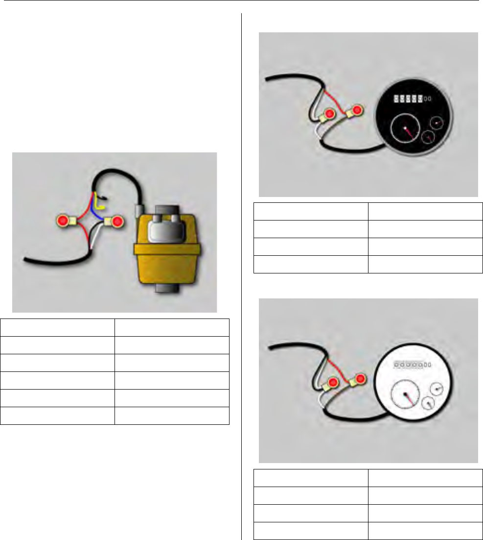
MTU Instruction
for AMCO and ABB Water Meters
Step 3 – Make a final visual check of the
wiring from the MTU to the meter register.
Verify that the cable routing is neat,
secure and professional.
Step 4 – Once installation and wiring are
complete, program the MTU using the
STAR Programmer Software and your
MTU Programmer.
V100/PSMT
MTU Cable V100/PSMT Cable
Red Red
Black Blue
White Blue
No Connection Black
No Connection Yellow
S130/5UM Hot Water
MTU Cable S130/5UM Cable
Red Brown
Black White
White White
S130/5UM Cold Water
MTU Cable S130/5UM Cable
Red Brown
Black White
White White
Page 53

MTU Instruction
for AMCO and ABB Water Meters
Intentionally Left Blank
Page 54
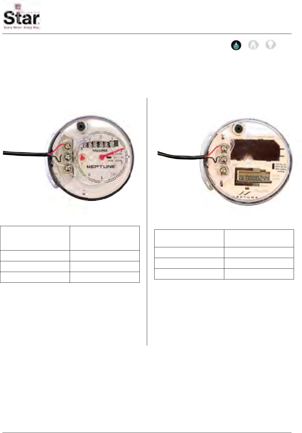
MTU Instruction
for Neptune and Schlumberger Water Meters
Purpose & Scope
This instruction provides wiring information for use in connecting a STAR MTU to Neptune
and/or Schlumberger water meters (all sizes) equipped with ARB-V, Auto/ProRead, or
E-Coder PLUS registers.
ARB-V or Auto/ProRead
MTU Cable ARB-V or
Auto/ProRead
Register
Red B (Black)
Black G (Green)
White R (Red)
Notes:
• Auto/ProRead registers must be
programmed by the manufacturer for
3-wire mode.
E-Coder PLUS
MTU Cable E-Coder PLUS
Register
Red B (Black)
Black G (Green)
White R (Red)
Notes:
• E-Coder Plus registers require a
special purpose NTG MTU (Hexagram
Part Number 501-11586D) to make
use of the E-Coder’s advanced leak,
tamper and reverse flow detection
capabilities.
471-2010 - 8/6/2006
Page 55
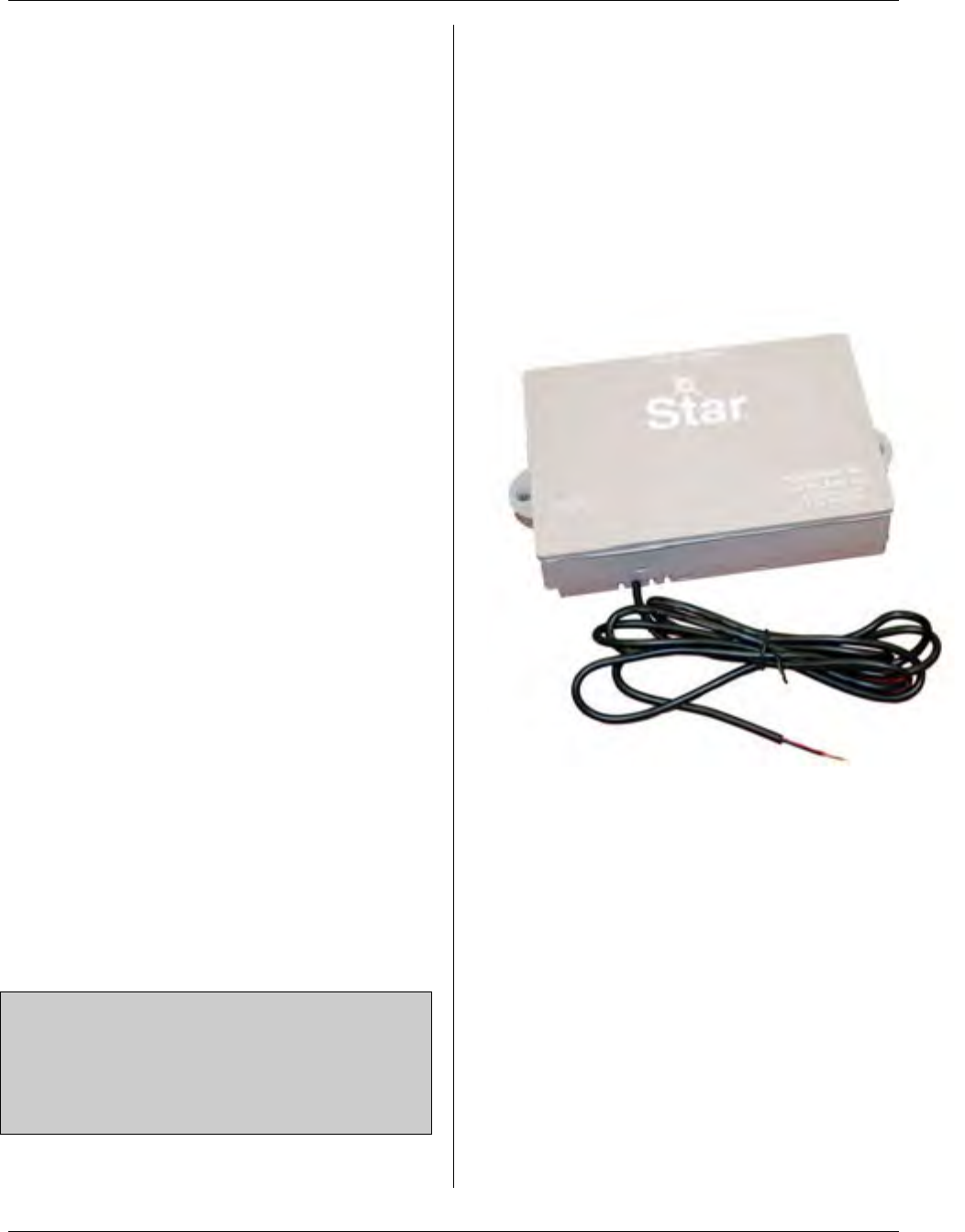
MTU Instruction
for Neptune and Schlumberger Water Meters
Supplies and Tools Required
See Publication 471-2000, General
Installation and Wiring Guidelines for a
complete list of recommended tools and
supplies for MTU Installation.
Installation Procedure
Step 1 - Select a mounting location for
the MTU that will allow optimum signal
transmission, and install any needed
wiring. Be sure to follow all General
Installation and Wiring Guidelines as
outlined in Publication 471-2000.
Step 2 – Select the wiring diagram that
applies to the meter you are connecting
and make the appropriate wiring
connections.
a. Direct Wiring to Meter - MTU
wiring is supplied stripped to a
standard length that fits water
meters with screw terminals.
Simply wrap the wires around the
screw terminal and tighten the
screw. It is recommended that the
screws be tightened to no more
than 4 – 5 in-lbs. Over-tightening
the screw can stress and possibly
fracture the wire.
b. Water Meter with Integral Cable -
If the water meter is supplied with
an integral cable and a cable-to-
cable splice is necessary, use a
gel-filled wire splice designed for
outdoor (moisture applications) to
seal the individual connections.
Note: When connecting a dual port MTU
to a compound meter, connect port 1
(black jacket) to the primary, or high-flow
register and port 2 (grey jacket) to the
secondary or low-flow register.
Step 3 – Make a final visual check of the
wiring from the MTU to the meter register.
Verify that the cable routing is neat,
secure and professional.
Step 4 – Once installation and wiring are
complete, program the MTU using the
STAR Programmer Software and your
MTU Programmer.
NTG MTU
The NTG MTU is a special purpose MTU
designed specifically to support the
advanced capabilities of Neptune’s E-
Coder solid-state register. This MTU
provides the following special functions
when coupled to an E-Coder Plus register
and properly programmed.
• 8-Digit Readings – The NTG MTU
reads and transmits the full 8-digit
reading from the E-Coder at the
programmed read interval, typically
every 12 hours. A full range of
read intervals are supported,
including temporary read intervals
for temporary monitoring purposes.
Page 56
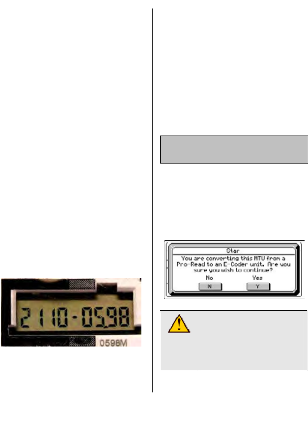
MTU Instruction
for Neptune and Schlumberger Water Meters
• Alarm Polling – The NTG MTU
also automatically polls (reads) the
E-Coder alarm indicators every 15
minutes. This happens
automatically, independently of the
standard read interval mentioned
above. If the NTG MTU detects
any change in the alarm status
of the E-Coder Plus register, an
alarm transmission is generated
immediately, reporting the change
in alarm status to the DCUs.
Compatibility with Neptune
E-Coder Registers
Hexagram’s NTG MTU is compatible with
Neptune E-Coder Plus solid state
registers revision 05.98 or higher.
Checking E-Coder Revision
Level
To check the revision level of an E-Coder
register, use your hand to block all light
from striking the E-Coder’s solar cell for
approximately 20 seconds. Then,
remove your hand allowing light to strike
the solar cell. The E-Coder’s display will
briefly flash all 8s, and then reveal a
display like that shown below.
The four digit number at the right of the
display is the revision level. In the
illustration above, the revision level
shown is 05.98.
Compatibility with Neptune
ARB-V and ProRead
Registers
Upon initial installation, an NTG MTU can
also be used with meters equipped with
Neptune’s ARB-V or ProRead registers.
These are standard absolute encoder
registers without the advanced
capabilities of the E-Coder register.
When used with ARB-V or ProRead
registers, the NTG MTU operates in
standard mode, providing 6-digit readings
and no specialized alarm polling.
Note: Auto/ProRead registers must be
programmed by the manufacturer for 3-
wire mode.
It is important to note that once an NTG
MTU is programmed to function in the
advanced mode with an E-Coder register,
it can no longer be returned to standard
operation. To caution the user, the
display shown below will appear when
first programming an NTG MTU for use
with an E-Coder:
CAUTION!
Once an NTG MTU is
programmed for use with an
E-Coder it can no longer be
used with other (non-E-Coder)
registers.
Page 57
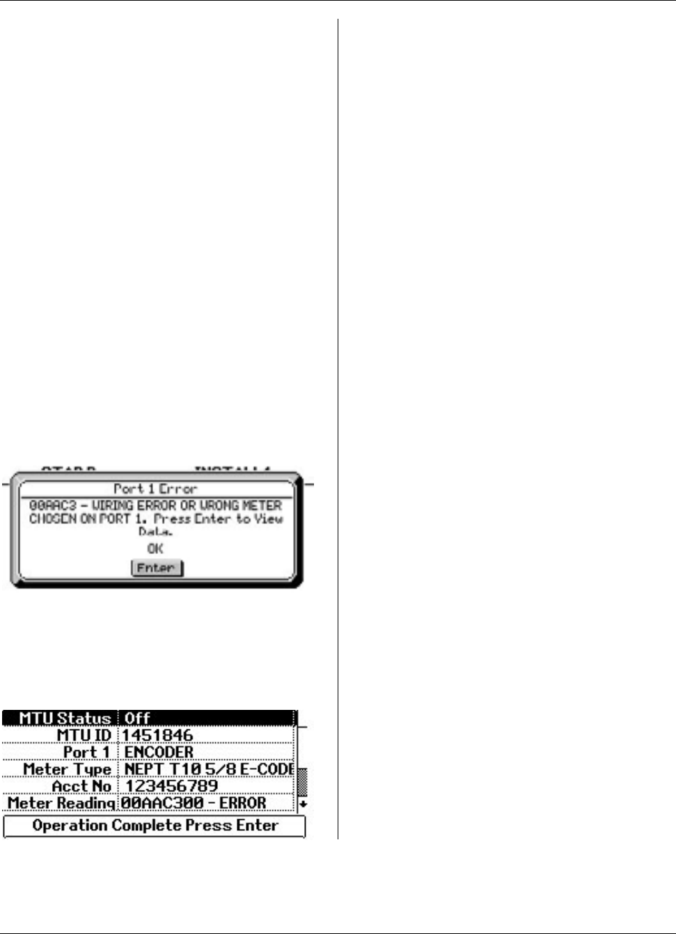
MTU Instruction
for Neptune and Schlumberger Water Meters
Once the user selects Yes on the above
screen and successfully completes
programming the NTG MTU for use with
an E-Coder Plus register, the NTG MTU
can no longer be used with an ARB-V or
ProRead register. From this point
forward, only E-Coder meter types will be
available for selection when programming
this NTG MTU.
Error Codes
When an E-Coder meter type is selected
while programming an NTG MTU with the
MTU Programmer, the MTU attempts to
communicate with the register using a
special protocol that reads the status of
the E-Coders leak, tamper and reverse
flow detection indicators. If the MTU
cannot successfully communicate with
the register, an error code will be
displayed on the MTU Programmer, as
shown below.
Pressing Enter in response to this
display will display the current settings for
the MTU, including the error code, as
shown below.
This error indicates one of the following
problems:
• Attempting to use an E-Coder
meter type with a register that is
not an E-Coder.
• A defective E-Coder register.
• Improper wiring between the NTG
MTU and the E-Coder. (Refer to
Publication 471-2110 for E-Coder
wiring information.)
Page 58

MTU Instruction
for Sensus and Invensys Water Meters
Purpose & Scope
This instruction provides wiring information for use in connecting a STAR MTU to Sensus
and/or Invensys water meters (all sizes) equipped with ECR or ICE registers.
ECR or ICE
MTU Cable Sensus/Invensys
Register
Red R (Red)
Black B (Black)
White G (Green)
Supplies and Tools Required
See Publication 471-2000, General
Installation and Wiring Guidelines for a
complete list of recommended tools and
supplies for MTU Installation.
Application Notes
• The 8-digit Sensus ICE Register must
be programmed to deliver 6
consecutive digits of reading
information for proper operation with
STAR MTUs.
Installation Procedure
Step 1 - Select a mounting location for
the MTU that will allow optimum signal
transmission, and install any needed
wiring. Be sure to follow all General
Installation and Wiring Guidelines as
outlined in Publication 471-2000.
Step 2 – Select the wiring diagram that
applies to the meter you are connecting
and make the appropriate wiring
connections.
a. Direct Wiring to Meter - MTU
wiring is supplied stripped to a
standard length that fits water
meters with screw terminals.
Simply wrap the wires around the
screw terminal and tighten the
screw. It is recommended that the
screws be tightened to no more
than 4 – 5 in-lbs. Overtightening
the screw can stress and possibly
fracture the wire.
b. Water Meter with Integral Cable -
If the water meter is supplied with
an integral cable and a cable-to-
cable splice is necessary, use a
gel-filled wire splice designed for
outdoor (moisture applications) to
seal the individual connections.
Note: When connecting a dual port MTU
to a compound meter, connect port 1
(black jacket) to the primary, or high-flow
register and port 2 (grey jacket) to the
secondary or low-flow register.
471-2011 - 2/28/2006
Page 59

MTU Instruction
for Sensus and Invensys Water Meters
Step 3 – Make a final visual check of the
wiring from the MTU to the meter register.
Verify that the cable routing is neat,
secure and professional.
Step 4 – Once installation and wiring are
complete, program the MTU using the
STAR Programmer Software and your
MTU Programmer.
Page 60
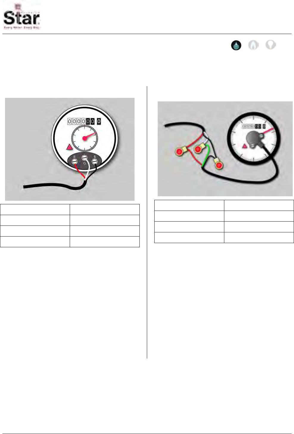
MTU Instruction
for Hersey Water Meters
Purpose & Scope
This instruction provides wiring information for use in connecting a STAR MTU to Hersey
water meters (all sizes) equipped with Translator or ER2 registers.
Translator
MTU Cable Hersey Register
Red R (Red)
Black B (Black)
White G (Green)
ER2
MTU Cable ER2 Cable
Red R (Red)
Black B (Black)
White G (Green)
Supplies and Tools Required
See Publication 471-2000, General
Installation and Wiring Guidelines for a
complete list of recommended tools and
supplies for MTU Installation.
Application Notes
• The Hersey Translator Register must
be programmed for 6-digit readings for
proper operation with STAR MTUs.
Installation Procedure
Step 1 - Select a mounting location for
the MTU that will allow optimum signal
transmission, and install any needed
wiring. Be sure to follow all General
Installation and Wiring Guidelines as
outlined in Publication 471-2000.
Step 2 – Select the wiring diagram that
applies to the meter you are connecting
and make the appropriate wiring
connections.
471-2012 - 2/28/2006
Page 61

MTU Instruction
for Hersey Water Meters
a. Direct Wiring to Meter - MTU
wiring is supplied stripped to a
standard length that fits water
meters with screw terminals.
Simply wrap the wires around the
screw terminal and tighten the
screw. It is recommended that the
screws be tightened to no more
than 4 – 5 in-lbs. Overtightening
the screw can stress and possibly
fracture the wire.
b. Water Meter with Integral Cable -
If the water meter is supplied with
an integral cable and a cable-to-
cable splice is necessary, use a
gel-filled wire splice designed for
outdoor (moisture applications) to
seal the individual connections.
Note: When connecting a dual port MTU
to a compound meter, connect port 1
(black jacket) to the primary, or high-flow
register and port 2 (grey jacket) to the
secondary or low-flow register.
Step 3 – Make a final visual check of the
wiring from the MTU to the meter register.
Verify that the cable routing is neat,
secure and professional.
Step 4 – Once installation and wiring are
complete, program the MTU using the
STAR Programmer Software and your
MTU Programmer.
Page 62
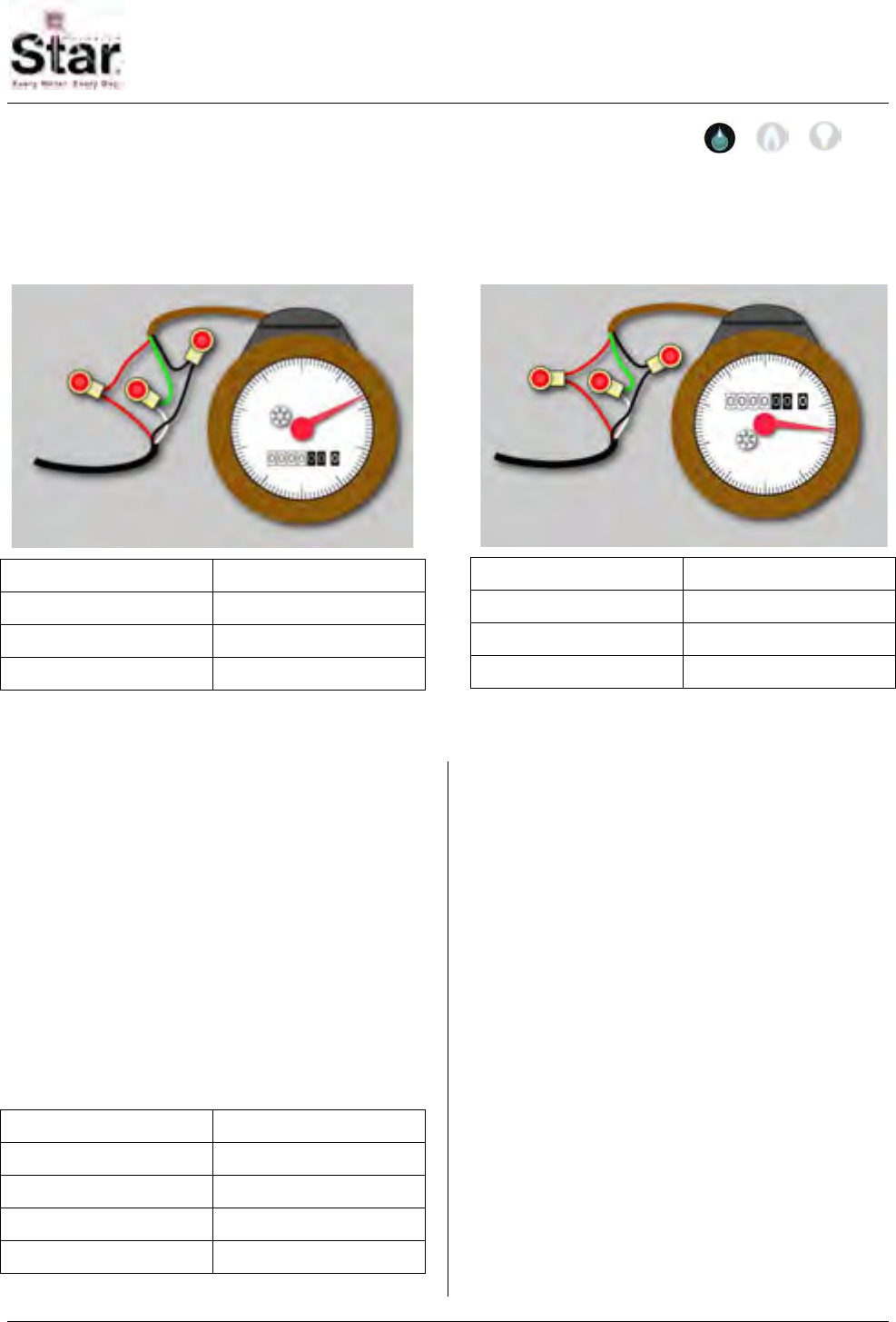
MTU Instruction
for Badger Water Meters
Purpose & Scope
This instruction provides wiring information for use in connecting a STAR MTU to Badger
water meters (all sizes) equipped with Read-O-Matic, RTR, or ADE registers.
RTR
MTU Cable RTR Cable
Red R (Red)
Black B (Black)
White G (Green)
ADE
MTU Cable ADE Cable
Red R (Red)
Black B (Black)
White G (Green)
Supplies and Tools Required
See Publication 471-2000, General
Installation and Wiring Guidelines for a
complete list of recommended tools and
supplies for MTU Installation.
Application Notes
• Some Badger RTR registers may be
provided with only a black wire and a
white wire with a shield. For this
variation, Trim the shield off and
connect as shown below.
MTU Cable RTR Cable
Black B (Black)
White B (Black)
Red W (White)
No Connection White-Shield
• The Badger ADE register must be
programmed for 6-digit readings for
proper operation with a STAR MTU.
Installation Procedure
Step 1 - Select a mounting location for
the MTU that will allow optimum signal
transmission, and install any needed
wiring. Be sure to follow all General
Installation and Wiring Guidelines as
outlined in Publication 471-2000.
Step 2 – Select the wiring diagram that
applies to the meter you are connecting
and make the appropriate wiring
connections.
a. Water Meter with Integral Cable -
If the water meter is supplied with
an integral cable and a cable-to-
cable splice is necessary, use a
gel-filled wire splice designed for
471-2013 - 2/28/2006
Page 63
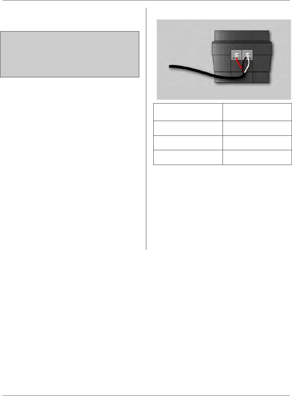
MTU Instruction
for Badger Water Meters
outdoor (moisture applications) to
seal the individual connections.
Note: When connecting a dual port MTU
to a compound meter, connect port 1
(black jacket) to the primary, or high-flow
register and port 2 (grey jacket) to the
secondary or low-flow register.
b. Direct Wiring to Meter - MTU
wiring is supplied stripped to a
standard length that fits water
meters with screw terminals.
Simply wrap the wires around the
screw terminal and tighten the
screw. It is recommended that the
screws be tightened to no more
than 4 – 5 in-lbs. Overtightening
the screw can stress and possibly
fracture the wire.
Step 3 – Make a final visual check of the
wiring from the MTU to the meter register.
Verify that the cable routing is neat,
secure and professional.
Step 4 – Once installation and wiring are
complete, program the MTU using the
STAR Programmer Software and your
MTU Programmer.
Read-O-Matic
MTU Cable Read-O-Matic
Terminals
Red + Positive
Black - Negative
White - Negative
Page 64
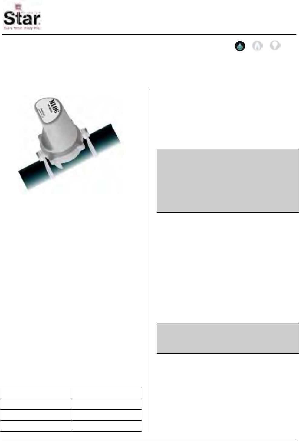
MTU Instruction
for MLOG Sensors
Purpose & Scope
This instruction provides wiring information for use in connecting a STAR encoder-type
MTU to a Flow Metrix MLOG Sensor.
Supplies and Tools Required
See Publication 471-2000, General
Installation and Wiring Guidelines for a
complete list of recommended tools and
supplies for MTU Installation.
Installation Procedure
Step 1 – Mount the MLOG Sensor in
accordance with the manufacturer’s
instructions.
Step 2 - Select a mounting location for
the MTU that will allow optimum signal
transmission, and install any needed
wiring. Be sure to follow all General
Installation and Wiring Guidelines as
outlined in Publication 471-2000.
Step 3 – Connect the three wires from
the MTU cable to the three wires of the
MLOG cable as shown in the following
table.
MTU Cable MLOG Sensor
Red R (Red)
Black B (Black)
White G (Green)
Use gel-filled wire splices designed for
outdoor applications to seal the individual
connections. For pit installations, seal
and enclose the three individual
connections using a direct burial splice kit
to complete the waterproof splice.
Note: If the MLOG sensor is connected to
a dual port MTU along with a meter, the
meter should be connected to port 1 and
the MLOG Sensor should be connected
to port 2. For a dual port MTU, port 1 is
the black jacketed cable and the port 2
cable has a grey jacket.
Step 4 – Make a final visual check of the
wiring from the MTU to the MLOG
Sensor. Verify that the cable routing is
neat, secure and professional.
Step 5 – Once installation and wiring are
complete, program the MTU using the
STAR Programmer Software and your
MTU Programmer. During programming,
select “MLOG LEAK DETECTOR” as the
meter type and set the read interval to 6
hours.
Note: The read interval for the MTU
connected to the MLOG Sensor MUST be
set for 6 hours.
Page 65

MTU Instruction
for MLOG Sensors
Intentionally Left Blank
Page 66
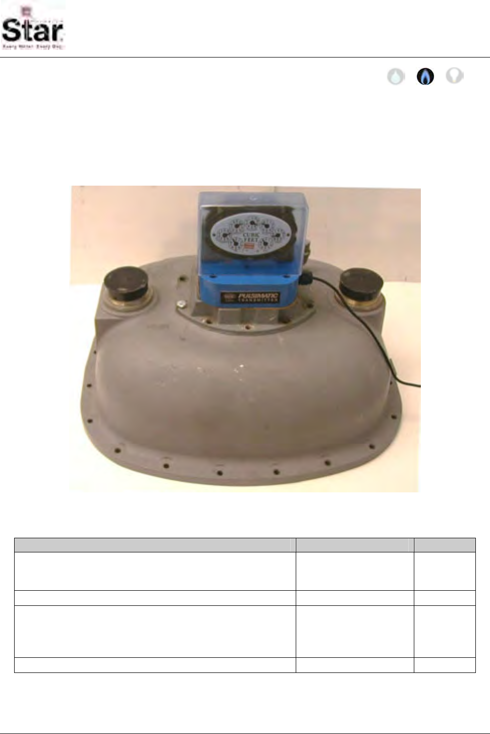
MTU Instruction
for Rockwell/Equimeter Model 750-10000 Gas Meters
Purpose & Scope
This instruction provides a procedure for use in connecting a STAR MTU to an IMAC
Pulsimatic Transmitter and installing the Pulsimatic Transmitter on a
Rockwell/Equimeter Model 750-10000 Intermediate or Large Capacity Diaphragm Gas
Meters. Please also refer to Publication 471-2000, General Installation and Wiring
Guidelines for general information covering the wiring and mounting of STAR MTUs.
Parts Required
Item Part Number Quantity
IMAC Pulsimatic Transmitter for Rockwell/Equimeter Model
750-10000 Intermediate and Large Capacity Diaphragm
Gas Meters. One pulse per revolution.
035-8150A 1
IMAC Mounting Hardware - Rockwell 069-8150F 1
Index Cover without security cap bosses
NOTE: This item is needed only if the existing Index Cover
has the security cap bosses. If the existing Index Cover
does not have the security cap bosses, it can be reused.
056-5155D 1
MTU, Reed/Weigand Pulse 501-6327R11
1 Any STAR MTU with an available Type R Port may be used for this installation.
471-2015 - 2/28/2006
Page 67
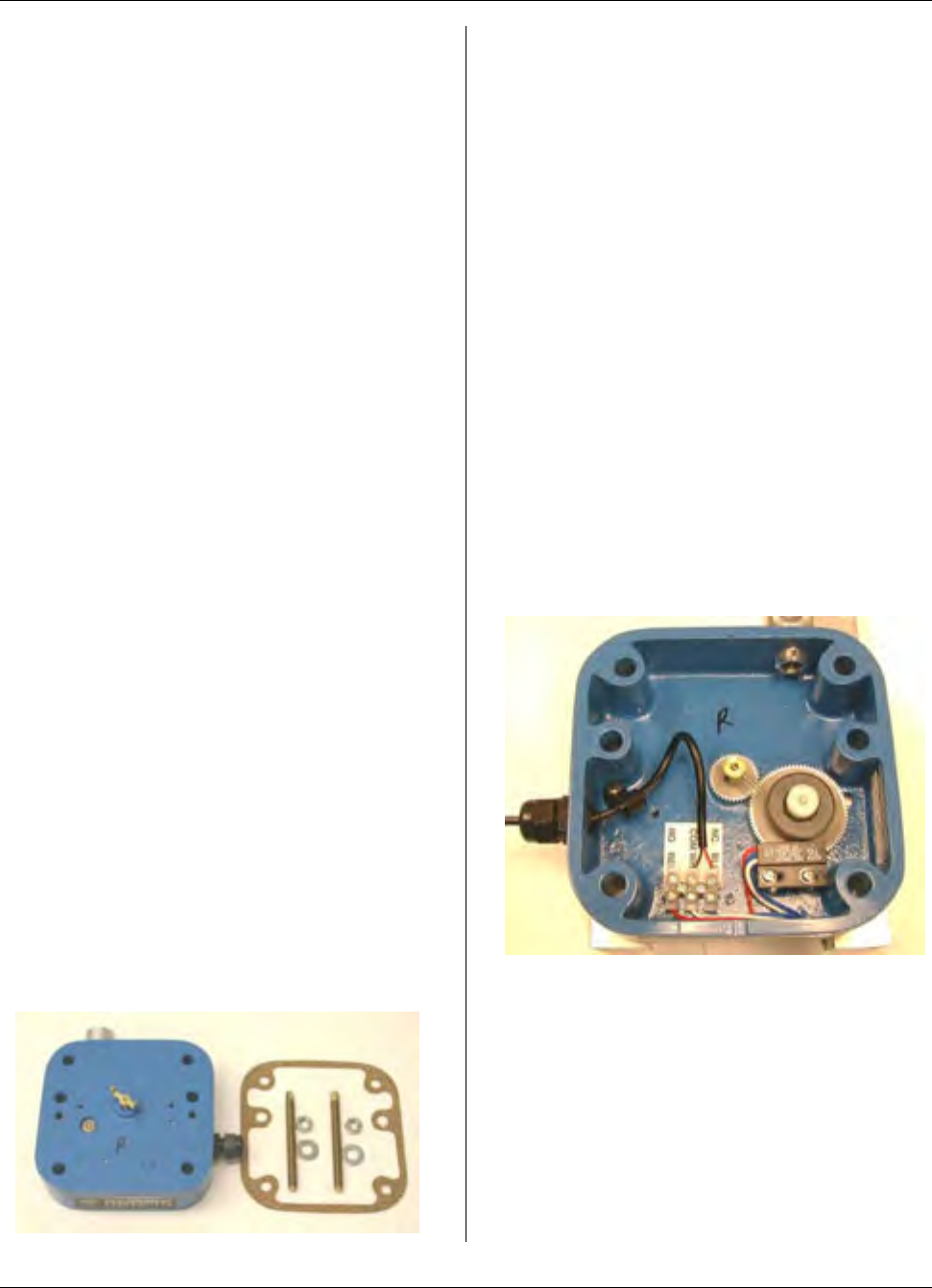
MTU Instruction
for Rockwell/Equimeter Model 750-10000 Gas Meters
Tools Required
• Slotted (Flat-blade) screwdrivers in
the following blade tip width sizes:
5/32” narrow-blade, 9/32”, and ½”.
If desired, use torque driver, 10
foot-lb. range.
• ½” combination (hand) wrench or
socket/ratchet wrench. A torque
wrench is recommended (30 inch-
lb. range).
• 8” adjustable wrench.
• 5/16-18 blind-hole (bottoming) tap
and mating size T-handle.
• Canned compressed air.
Also see Publication 471-2000, General
Installation and Wiring Guidelines for a
complete list of recommended tools and
supplies for MTU Installation.
Installation Procedure
There are two parts to this procedure.
First, the MTU must be wired to the IMAC
Pulsimatic Transmitter (IPT). Once this is
complete, you can then install the
Pulsimatic Transmitter onto the Rockwell
gas meter.
Wiring the MTU to the Pulsimatic
Step 1 – Unpack all of the components
required to install the IPT. This should
include the IPT itself, gasket and a
hardware kit that includes (2 each) brass
threaded rods, stainless flat-washers and
hex nuts.
Step 2 - When wiring to the IPT, support
the IPT off of the work surface on the
outside (topside) of its base so that
pressure is not applied to the center drive
shaft. Remove the cable clamp (screw)
from inside the base.
Step 3 – Trim the stripped ends of the
MTU cable to ¼” or slightly shorter. When
inserted into the terminal block, only a
small amount of bare wire should be
visible. Bare wire should not extend
beyond the walls of the terminal block.
This will present a shorting potential.
Step 4 – Feed the MTU input cable
through the sealtight strain relief in the
base of the IPT. Loop the cable so that
stripped ends of the wires can be easily
inserted into the terminal block screws.
The screws should already be open
enough. Place cable clamp over the wire
as shown.
Step 5 – Insert the BLACK and WHITE
wires into the COM terminal screw.
Tighten the screw.
Step 6 – Insert the RED wires into the NC
BLU terminal screw. Tighten the screw.
Page 68
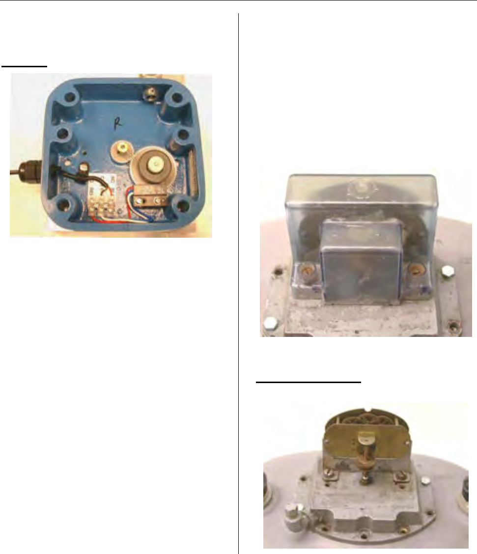
MTU Instruction
for Rockwell/Equimeter Model 750-10000 Gas Meters
Step 7 – Pull most of the slack out of the
cable (leave a slight amount of slack) and
reattach cable clamp as shown below.
DO NOT pull the cable taut.
Step 8 – Tighten the nut on the sealtight
strain relief. You will need to tighten the
nut almost fully down (as shown) before it
will bite on the MTU cable.
Step 9 – Check that all wired terminal
block screws are tight.
Step 10 – Depending on the installation
location, you may be able to mount the
MTU at this time. During installation, the
IPT body should be supported so as not
to hang (apply tension) on the MTU
cable. During the installation, do not allow
the heavier body of the IPT to suddenly
jerk the MTU cable as this could
potentially damage the cable internally.
Step 11 – Install the MTU into its
intended location per the recommended
procedure found in the standard
Hexagram MTU installation manual.
Installing the Pulsimatic
Transmitter
Step 1 – If necessary, remove tamper
seals that cover the index cover screws.
Loosen and remove screws securing the
index cover. You may discard these
screws as they will not be re-used.
Remove the cover. If the cover has the
tamper seal bosses, this cover will be
need to be replaced.
Step 2 – Loosen and remove the screws
securing the index to the index plate.
Save these screws as they will be re-
used. Remove the index and set aside.
Page 69
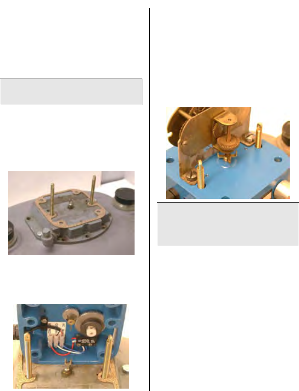
MTU Instruction
for Rockwell/Equimeter Model 750-10000 Gas Meters
Step 3 – If the index cover screws were
difficult to remove, the threads in the
index plate may need to be cleaned out
before installing the hardware that retains
the IPT. Use the blind-hole tap to
carefully clean out/ clean up the threads
of the (2) cover holes. Blow out the holes
with compressed (canned) air.
NOTE: It is not necessary to clean the
index mounting-hole threads as these
holes are not reused.
Step 4 – Thread the (full thread) ends of
the securing studs (2) into the index cover
screw holes of the index plate. Lightly
snug the studs by grasping them by the
flat that is machined into the top of the
stud. Apply the gasket over the studs as
shown.
Step 5 – Before setting the IPT over the
mounting studs, you must align the shaft
drive pin of the IPT so that it will engage
inside the fork portion of the meter drive
foot.
Step 6 – Place the IPT (middle set of
holes) over the mounting studs. Make
sure that the IPT drive pin engages the
fork of the meter drive foot.
Step 7 – Mount the register onto the base
of the IPT using the same screws that
originally secured the register to the index
plate (meter head). The drive foot of the
index must engage the fork of the IPT
drive shaft. Tighten/torque the screws to
approximately 4-5 ft-lb.
NOTE: If the index cover that was
removed has the security cap boss
extensions, this cover will need to be
replaced with an index cover without the
security cap bosses.
Step 8 – Although not necessary, it may
be desired to keep water or dirt from
collecting in the unused corner mounting
holes. If closing them is desired, use a
permanent outdoor rated non-shrinking
putty or caulk such as an RTV.
Page 70
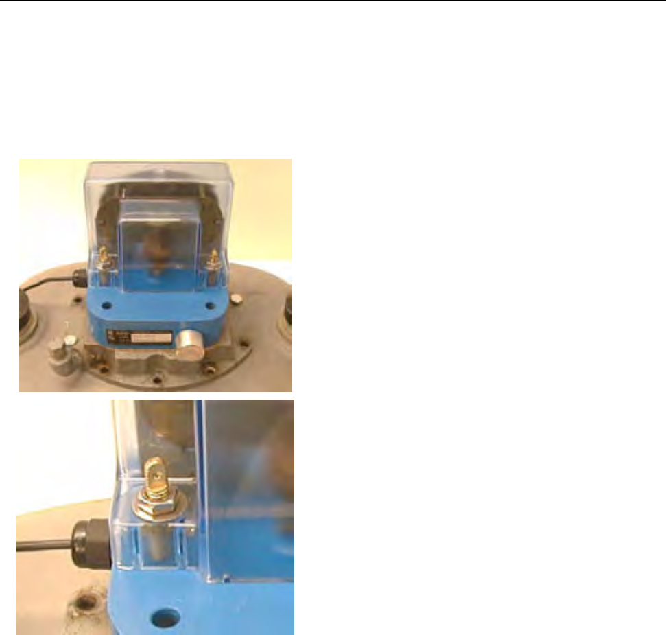
MTU Instruction
for Rockwell/Equimeter Model 750-10000 Gas Meters
Step 9 – Place the index cover onto the
studs. It will fit over the index one way
only. Apply a flat washer and nut onto
each stud. Snug, and then tighten these
nuts an additional ½ to ¾ turn maximum.
The finished torque value is 25 – 30 inch-
lb.
Step 10 – Install Wire/Lead security seals
if desired. Installation is complete.
Page 71

MTU Instruction
for Rockwell/Equimeter Model 750-10000 Gas Meters
Intentionally Left Blank
Page 72
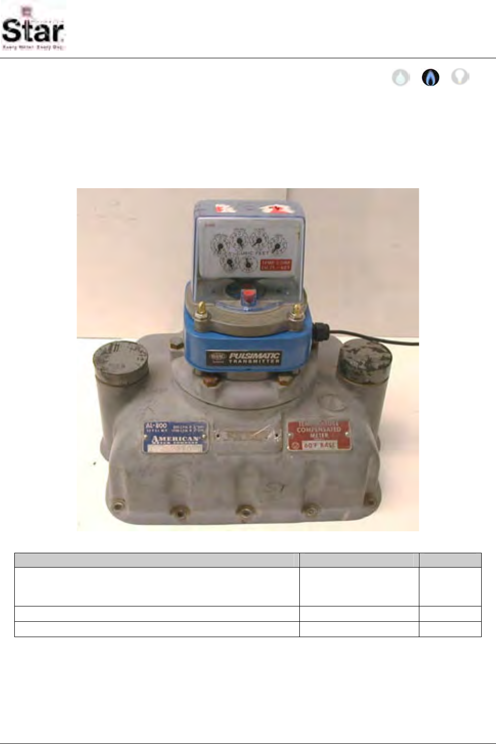
MTU Instruction
for American Model AL800-AL5000 Gas Meters
Purpose & Scope
This instruction provides a procedure for use in connecting a STAR MTU to an IMAC
Pulsimatic Transmitter and installing the Pulsimatic Transmitter on an American Model
AL800-AL5000 Industrial & Commercial Diaphragm Gas Meters. Please also refer to
Publication 471-2000, General Installation and Wiring Guidelines for general information
covering the wiring and mounting of STAR MTUs.
Parts Required
Item Part Number Quantity
IMAC Pulsimatic Transmitter for American Models AL800-
AL5000 Commercial and Industrial Diaphragm Gas Meters.
One pulse per revolution. Long shaft.
035-8150B 1
IMAC Mounting Hardware - American 069-8150G 1
MTU 501-6327R11
1 Any STAR MTU with an available Type R Port may be used for this installation.
471-2016 - 2/28/2006
Page 73
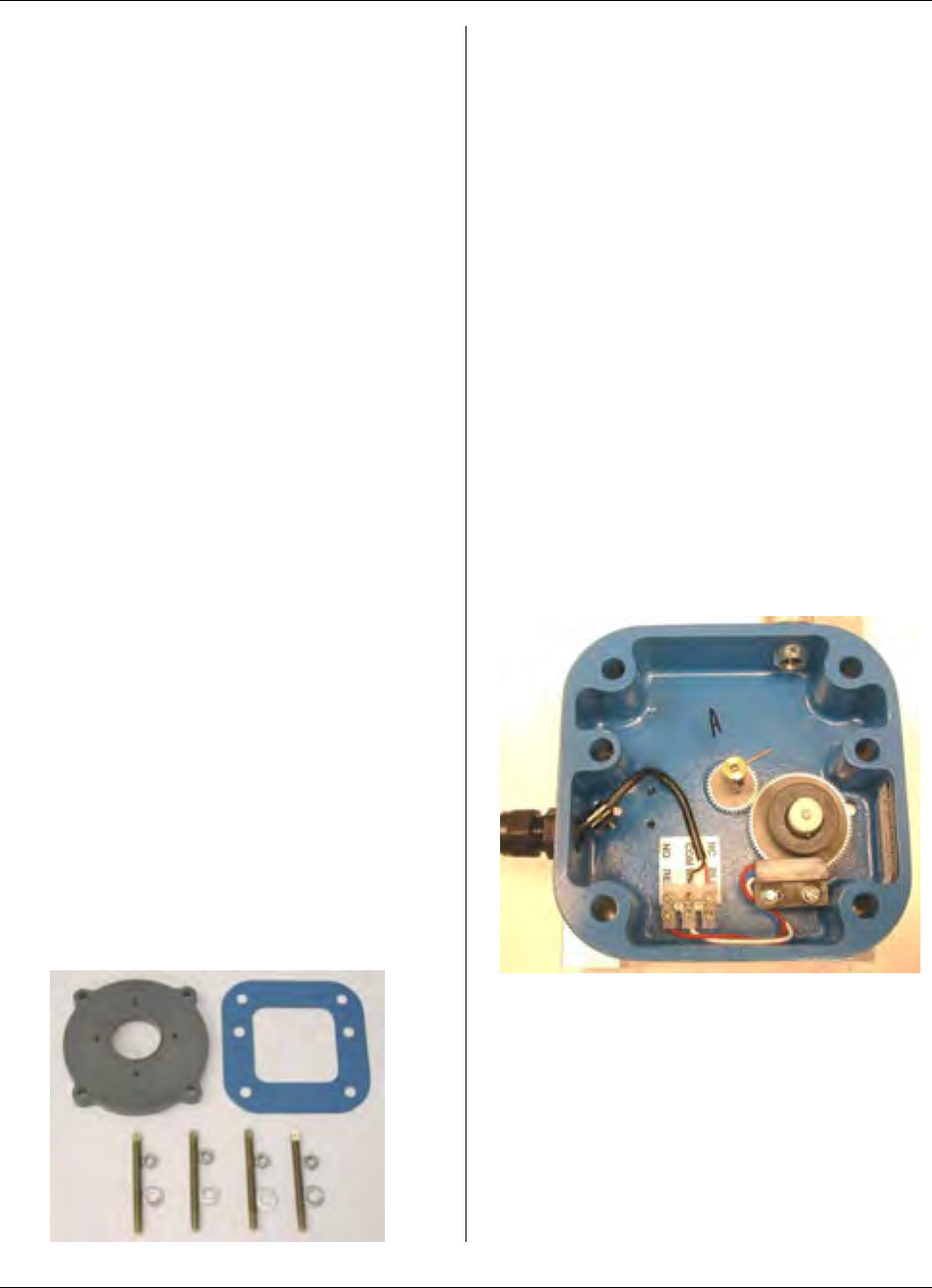
MTU Instruction
for American Model AL800-AL5000 Gas Meters
Tools Required
• Slotted (Flat-blade) screwdrivers in
the following blade tip width sizes:
5/32” narrow-blade, 9/32”, and ½”.
• ½” combination (hand) wrench or
socket/ratchet wrench. A torque
wrench is recommended (60 inch-lb.
range).
• 8” adjustable wrench.
• 18-18 blind-hole (bottoming) tap and
mating size T-handle.
• Canned compressed air.
Also see Publication 471-2000, General
Installation and Wiring Guidelines for a
complete list of recommended tools and
supplies for MTU Installation.
Installation Procedure
There are two parts to this procedure.
First, the MTU must be wired to the IMAC
Pulsimatic Transmitter (IPT). Once this is
complete, you can then install the
Pulsimatic Transmitter onto the American
gas meter.
Wiring the MTU to the Pulsimatic
Step 1 – Unpack all of the components
required to install the IPT. This will
generally include the IPT itself, gasket
and a hardware kit that includes (2 each)
brass threaded rods, stainless flat-
washers and hex nuts.
Step 2 - When wiring to the IPT, support
the IPT off of the work surface on the
outside (topside) of its base so that
pressure is not applied to the center drive
shaft. Remove the cable clamp (screw)
from inside the base.
Step 3 – Trim the stripped ends of the
MTU cable to ¼” or slightly shorter. When
inserted into the terminal block, only a
small amount of bare wire should be
visible. Bare wire should not extend
beyond the walls of the terminal block.
This will present a shorting potential.
Step 4 – Feed the MTU input cable
through the sealtight strain relief in the
base of the IPT. Loop the cable so that
stripped ends of the wires can be easily
inserted into the terminal block screws.
The screws should already be open
enough. Place cable clamp over the wire
as shown.
Step 5 – Insert the BLACK and WHITE
wires into the COM terminal screw.
Tighten the screw.
Step 6 – Insert the RED wires into the NC
BLU terminal screw. Tighten the screw.
Page 74
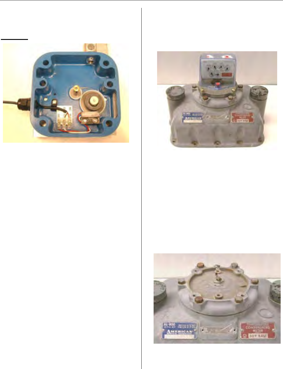
MTU Instruction
for American Model AL800-AL5000 Gas Meters
Step 7 – Pull most of the slack out of the
cable (leave a slight amount of slack) and
reattach cable clamp as shown below.
DO NOT pull the cable taut.
Step 8 – Tighten the nut on the sealtight
strain relief. You will need to tighten the
nut almost fully down (as shown) before it
will bite on the MTU cable.
Step 9 – Check that all wired terminal
block screws are tight.
Step 10 – Depending on the installation
location, you may be able to mount the
MTU at this time. During installation, the
IPT body should be supported so as not
to hang (apply tension) on the MTU
cable. During the installation, do not allow
the heavier body of the IPT to suddenly
jerk the MTU cable as this could
potentially damage the cable internally.
Step 11 – Install the MTU into its
intended location per the recommended
procedure found in the standard
Hexagram MTU installation manual.
Installing the Pulsimatic
Transmitter
Step 1 – If necessary, remove tamper
seals from any of the 4 screws that
secure the index plate. Loosen and
remove the screws securing the index
plate assembly. You may discard these
screws as they will not be re-used.
Remove the index plate assembly from
the top of the meter. Do not disassemble
the index cover from the index plate.
Step 2 – If the index plate mounting
screws were difficult to remove, the
threads in the meter head (handhole
plate) may need to be cleaned out before
installing the hardware that will retain the
IPT and index plate stack. Use the blind-
hole tap to carefully clean out/ clean up
the threads of the (2) cover holes. NOTE
THAT THESE THREADS ARE #18-18.
MAKE SURE TO USE THE PROPER
TAP. Blow out the holes with compressed
(canned) air.
Page 75
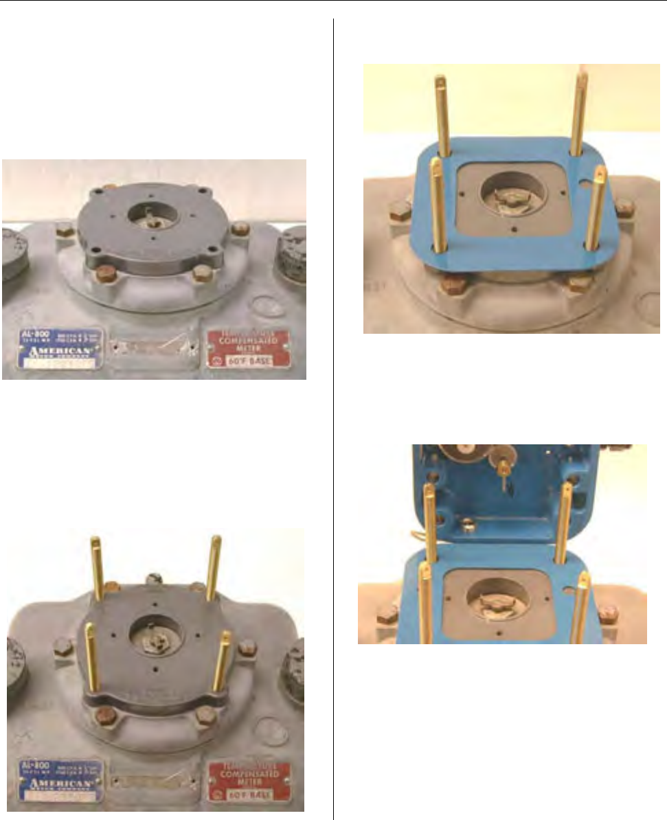
MTU Instruction
for American Model AL800-AL5000 Gas Meters
Step 3 – Place the adapter plate
contained in the installation parts onto the
head of the meter with the ear holes
aligned over the index plate mounting
holes of the meter head. The embossed
“AL800-AL5000” on the adapter plate is
oriented to the front of the meter.
Step 4 – AFTER PLACING THE
APAPTOR PLATE, Thread the (18-18
thread) ends of the securing studs (4) into
the index cover screw holes of the index
plate. Lightly snug the studs by grasping
them by the flat that is machined into the
top of the stud.
Step 5 - Apply the seal plate over the
studs.
Step 6 – Before setting the IPT over the
mounting studs, you must align the shaft
drive pin of the IPT so that it will engage
inside the fork portion of the meter drive
foot.
Page 76
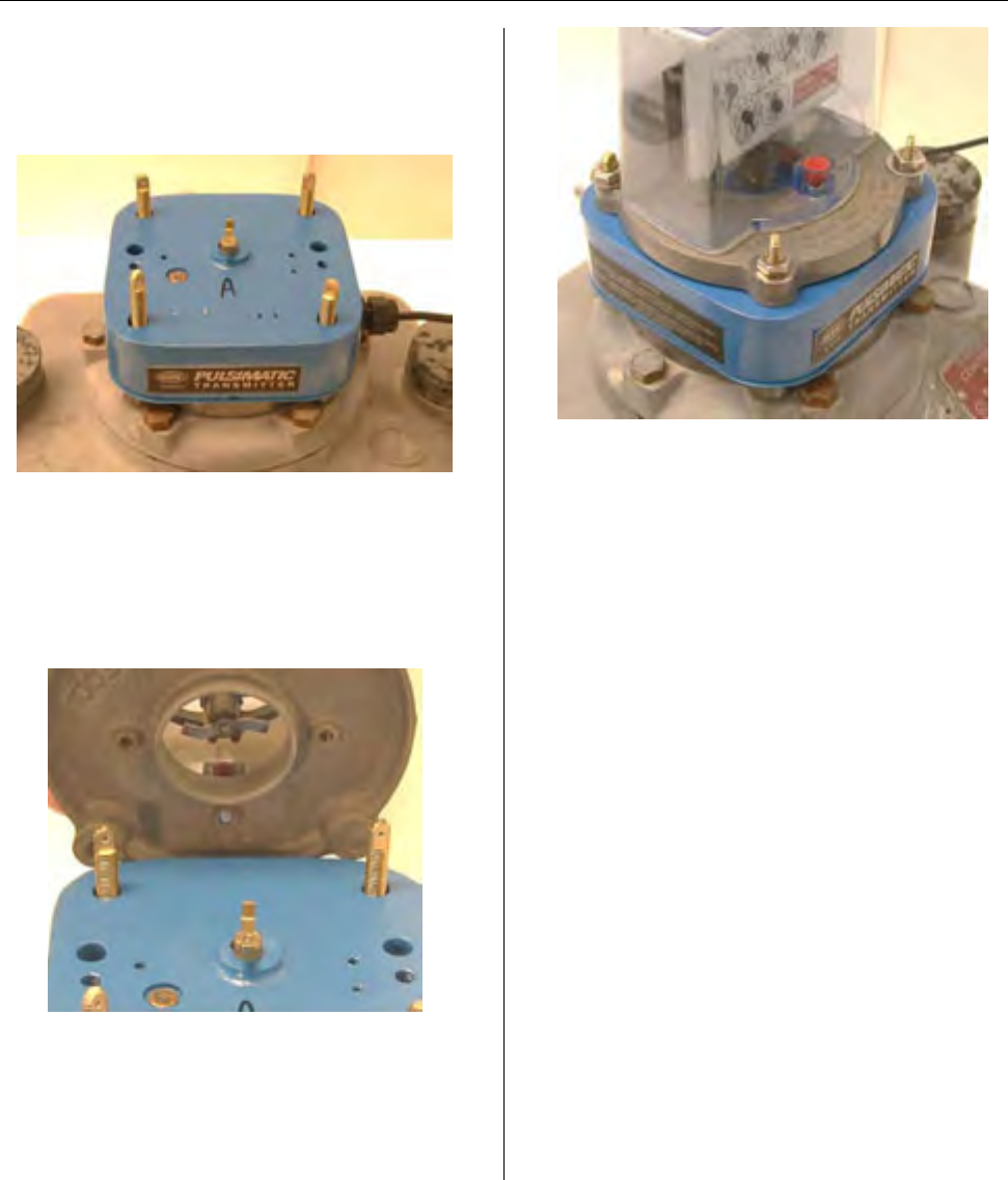
MTU Instruction
for American Model AL800-AL5000 Gas Meters
Step 7 – Place the IPT (4 corner holes)
over the mounting studs. Make sure that
the IPT drive pin engages the fork of the
meter drive foot.
Step 10 – Install Wire/Lead security seals
if desired. Installation is complete.
Step 8 – Before mounting the index plate
assembly, the drive foot of the index must
engage the fork of the IPT drive shaft.
Mount the index plate assembly onto the
base of the IPT over the same (4) corner
studs.
Step 9 – Complete the assembly by
securing the index plate onto the studs,
with the supplied (4) flat washers and
nuts. Tighten these nuts a finished torque
of 60 inch-lb. (5 ft-lb.).
Page 77

MTU Instruction
for American Model AL800-AL5000 Gas Meters
Intentionally Left Blank
Page 78
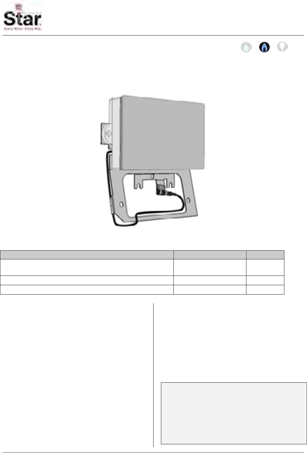
MTU Instruction
for Sprague/Schlumberger/Actaris Gas Meters
Purpose & Scope
This instruction provides a procedure for installing a STAR bracket direct-mount MTU on a
Sprague/Schlumberger/Actaris Model 175, 250 or 400 and 400A (slant-face) Gas
Meter.
Parts Required
Item Part Number Quantity
MTU, Bracket Direct Mount, for Sprague 175, 250 and 400 501-8150H-A or
501-8150HD5-A 1
#10-24 x 3/8” Slotted Fillister Head Machine Screw 069-102412HA 2
Wheel/Magnet Assembly 109-7126A 1
Tools Required
To mount the MTU to these meters, you
will need the following tools and
equipment:
• Safety goggles
• #1 and #2 Phillips screwdrivers
• #1 and #2 Slotted screwdrivers
• 5/32” diameter medium grit
tapered round file
• Metal nibbler tool, 1/8” cut
• Small, diagonal plastic cutting
pliers
See Publication 471-2000, General
Installation and Wiring Guidelines for a
complete list of recommended tools and
supplies for MTU Installation.
Installation Procedure
Before installing the MTU, anti-tamper,
safety, and security hardware must be
removed from the clear index cover.
Note: Early slant-face Sprague gas
meters were equipped with a cast
aluminum framed index cover held in
place by two screws. Later models are
equipped with a plastic index cover held
in place by three screws. This procedure
can be used with either style.
471-2017 - 2/28/2006
Page 79
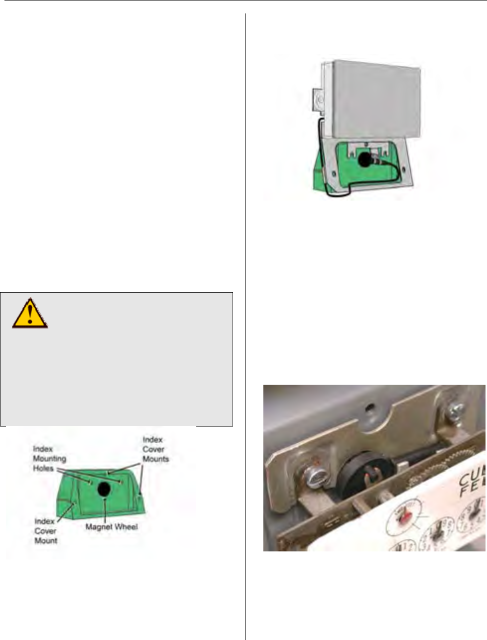
MTU Instruction
for Sprague/Schlumberger/Actaris Gas Meters
Step 1 – Remove the clear index cover
from the meter by removing the screws
that hold it. The clear index cover and
index cover screws will be reused. Clean
and inspect these items and set them
aside until needed. Replace if damaged.
Step 2 – Remove the index by removing
the two screws that hold it to the meter.
Set the Index aside until later. The
screws that held the index to the meter
can be discarded.
Step 3 – Remove the drive foot from the
meter drive shaft by unthreading it
counterclockwise. The drive foot will not
be reused and can be discarded. Then,
thread the magnet wheel clockwise onto
the shaft. Tighten the magnet wheel until
snug to the end of the threads on the
drive shaft.
CAUTION!
Be careful not to cross-thread
the magnet wheel when
installing it on the meter drive
shaft. Cross-threading can
cause misalignment of the
magnet wheel which in turn
can cause binding or erratic
performance.
Step 4 – Thread the two #10-24 x 3/8”
machine screws provided about one full
turn into the index mounting holes.
Step 5 – Place the MTU bracket
assembly into position on the meter,
hooking the two tabs on the bracket
behind the heads of the index mounting
screws.
Step 6 – Replace the index by hooking
the two tabs on the index behind the
heads of the index mounting screws.
Insure that the drive foot on the index will
be driven by the pin on the magnet wheel
as it rotates. Several styles of indexes
and index drive mechanisms may be
encountered. Use the photos below as a
guide. Note that on indexes with a slotted
drive foot, it is intended that the pin on the
magnet wheel engages the slot on the
drive foot.
Brass Index with Slotted Drive Foot
Page 80
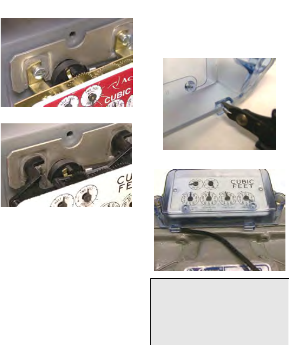
MTU Instruction
for Sprague/Schlumberger/Actaris Gas Meters
Brass Index with Offset Drive Foot
Plastic Index with Metal Drive Foot
Step 7 – Route the sensor wire so that it
does not interfere with the magnet wheel
or the index gears. Hand tighten index
mounting screws. Gently move the 2-foot
hand to check for some free play to
insure that the register is not binding up.
Step 8 – Notch the index cover to allow
the sensor wire to exit through the bottom
left edge. On the clear plastic index
cover, you can remove (cut away) the
inner tab from the molded drain opening
at on the bottom left edge of the cover.
Position clear index cover on meter head
and route sensor cable though notch.
NOTE: If the meter is equipped with a
cast aluminum framed index cover,
enlarge the drain hole at the bottom left
edge of the cover to approximately 5/32”
using a metal nibbler and/or tapered file.
Clean up any sharp edges with the
tapered file before mounting the index
cover.
Page 81

MTU Instruction
for Sprague/Schlumberger/Actaris Gas Meters
Step 9 – Secure MTU bracket assembly
and the clear index cover to the meter
head using the three screws that
originally held the clear index cover.
Tighten index cover screws.
Step 10 - Replace any anti-tamper,
safety, or security hardware onto the
clear index cover as required.
Step 11 – Once Installation is complete,
program the MTU using the STAR
Programmer Software and your MTU
Programmer.
Page 82
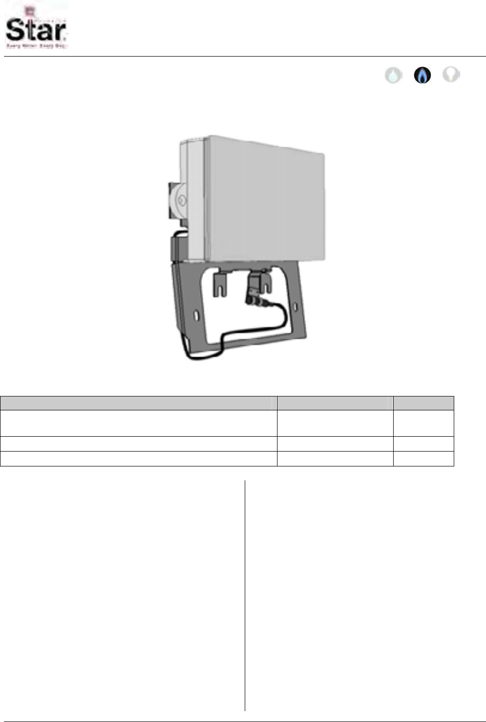
MTU Instruction
for Lancaster Model 250 Gas Meters
Purpose & Scope
This instruction provides a procedure for installing a STAR bracket direct-mount MTU on a
Lancaster Model 250 (slant-face) Gas Meter.
Parts Required
Item Part Number Quantity
MTU, Bracket Direct Mount, for Lancaster 250 501-8150H-B or
501-8150HD5-B 1
#10-24 x 3/8” Slotted Fillister Head Machine Screw 069-102412HA 2
Wheel/Magnet Assembly 109-7126A 1
Tools Required
To mount the MTU to these meters, you
will need the following tools and
equipment:
• Safety goggles
• #1 and #2 Phillips screwdrivers
• #1 and #2 Slotted screwdrivers
• 5/32” diameter medium grit
tapered round file
• Metal nibbler tool, 1/8” cut
• Small, diagonal plastic cutting
pliers
See Publication 471-2000, General
Installation and Wiring Guidelines for a
complete list of recommended tools and
supplies for MTU Installation.
Installation Procedure
Before installing the MTU, anti-tamper,
safety, and security hardware must be
removed from the clear index cover.
Step 1 – Remove the clear index cover
from the meter by removing the two
screws that hold it. The clear index cover
and index cover screws will be reused.
Clean and inspect these items and set
them aside until needed. Replace if
damaged.
471-2018 - 2/28/2006
Page 83
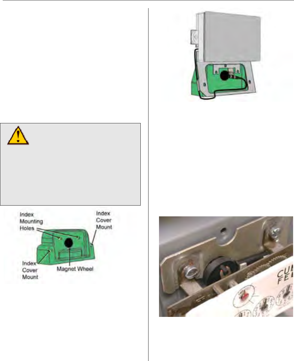
MTU Instruction
for Lancaster Model 250 Gas Meters
Step 2 – Remove the index by removing
the two screws that hold it to the meter.
Set the Index aside until later. The
screws that held the index to the meter
can be discarded.
Step 3 – Remove the drive foot from the
meter drive shaft by unthreading it
counterclockwise. The drive foot will not
be reused and can be discarded. Then,
thread the magnet wheel clockwise onto
the shaft. Tighten the magnet wheel until
snug to the end of the threads on the
drive shaft.
CAUTION!
Be careful not to cross-thread
the magnet wheel when
installing it on the meter drive
shaft. Cross-threading can
cause misalignment of the
magnet wheel which in turn
can cause binding or erratic
performance.
Step 4 – Thread the two #10-24 x 3/8”
machine screws provided about one full
turn into the index mounting holes.
Step 5 – Place the MTU bracket
assembly into position on the meter,
hooking the two tabs on the bracket
behind the heads of the index mounting
screws.
Step 6 – Replace the index by hooking
the two tabs on the index behind the
heads of the index mounting screws.
Insure that the drive foot on the index will
be driven by the pin on the magnet wheel
as it rotates. Several styles of indexes
and index drive mechanisms may be
encountered. Use the photos below as a
guide. Note that on indexes with a slotted
drive foot, it is intended that the pin on the
magnet wheel engages the slot on the
drive foot.
Brass Index with Slotted Drive Foot
Page 84
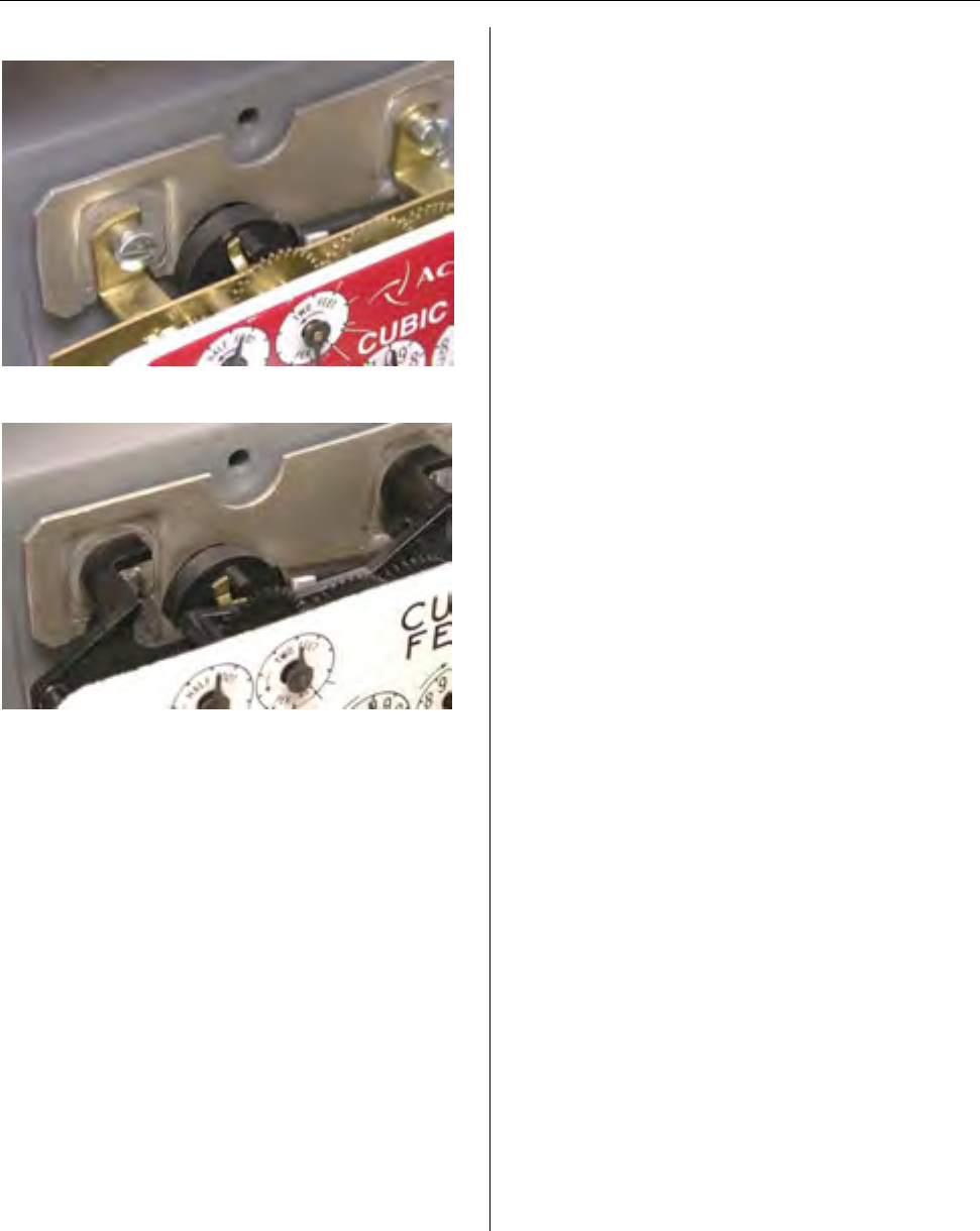
MTU Instruction
for Lancaster Model 250 Gas Meters
Brass Index with Offset Drive Foot
Plastic Index with Metal Drive Foot
Step 7 – Route the sensor wire so that it
does not interfere with the magnet wheel
or the index gears. Hand tighten index
mounting screws. Gently move the 2-foot
hand to check for some free play to
insure that the register is not binding up.
Step 8 – Next, create an exit notch for the
sensor wire by using a nibbler or plastic
cutting plier to add a notch approximately
5/32” in diameter to the bottom left edge
of the clear index cover. Do not interfere
with the drain hole already molded into
the clear index cover. Clean up the
edges of the notch using a round tapered
file. Then position clear index cover on
meter head and route sensor cable
though notch.
Step 9 – Secure MTU bracket assembly
and the clear index cover to the meter
head using the two screws that originally
held the clear index cover. Tighten index
cover screws.
Step 10 - Replace any anti-tamper,
safety, or security hardware onto the
clear index cover as required.
Step 11 – Once Installation is complete,
program the MTU using the STAR
Programmer Software and your MTU
Programmer.
Page 85

MTU Instruction
for Lancaster Model 250 Gas Meters
Intentionally Left Blank
Page 86
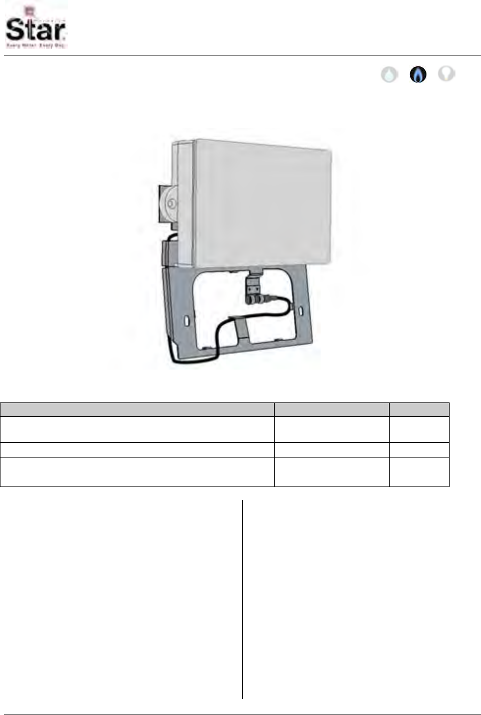
MTU Instruction
for Lancaster Model 175 Gas Meters
Purpose & Scope
This instruction provides a procedure for installing a STAR bracket direct-mount MTU on a
Lancaster Model 175 (slant-face) Gas Meter.
Parts Required
Item Part Number Quantity
MTU, Bracket Direct Mount, for Lancaster 175 501-8150H-C or
501-8150HD5-C 1
#6-32 x ¼” Phillips Panhead Machine Screw 069-063208AA 2
#6 Flat Washer (precision thickness) 069-2648 2
Wheel/Magnet Assembly 109-7126A 1
Tools Required
To mount the MTU to these meters, you
will need the following tools and
equipment:
• Safety goggles
• #1 and #2 Phillips screwdrivers
• #1 and #2 Slotted screwdrivers
• 5/32” diameter medium grit
tapered round file
• Metal nibbler tool, 1/8” cut
• Small, diagonal plastic cutting
pliers
See Publication 471-2000, General
Installation and Wiring Guidelines for a
complete list of recommended tools and
supplies for MTU Installation.
Installation Procedure
Before installing the MTU, anti-tamper,
safety, and security hardware must be
removed from the clear index cover.
471-2019 - 2/28/2006
Page 87
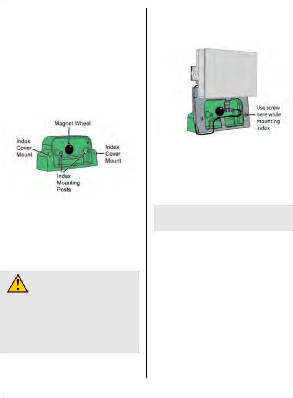
MTU Instruction
for Lancaster Model 175 Gas Meters
Step 1 – Remove the clear index cover
from the meter by removing the two
screws that hold it. The clear index cover
and index cover screws will be reused.
Clean and inspect these items and set
them aside until needed. Replace if
damaged.
Step 2 – Remove the index by removing
the two screws that hold it to the meter.
Set the index aside until later. The
screws that held the index to the meter
can be discarded.
Step 3 – Remove the drive foot from the
meter drive shaft by unthreading it
counterclockwise. The drive foot will not
be reused and can be discarded. Then,
thread the magnet wheel clockwise onto
the shaft. Tighten the magnet wheel until
snug to the end of the threads on the
drive shaft.
CAUTION!
Be careful not to cross-thread
the magnet wheel when
installing it on the meter drive
shaft. Cross-threading can
cause misalignment of the
magnet wheel which in turn
can cause binding or erratic
performance.
Step 4 – Place the MTU bracket
assembly into position on the meter. Use
an index cover screw to temporarily hold
the MTU bracket assembly in position.
Route the sensor wire around the right-
hand index-mounting post then back and
under the finger hook so that it does not
interfere with the magnet wheel or the
index gears.
Step 5 – Reattach the index to the meter
using the screws and washers provided.
Note: The washers provided are a
precision thickness designed to properly
position the index. Use no substitutes.
The washers are to be placed between
the back of the index and the mounting
posts. The screws provided with the
MTU replace the original index mounting
screws. Insure that the drive foot on the
index will be driven by the pin on the
magnet wheel as it rotates, then hand
tighten the index mounting screws.
Gently move the 2-foot hand to check for
some free play to insure that the register
is not binding up.
Step 6 – Next, create an exit notch for the
sensor wire by using a nibbler or plastic
cutting plier to add a notch approximately
5/32” in diameter to the bottom left edge
of the clear index cover. Do not interfere
with the drain hole already molded into
Page 88

MTU Instruction
for Lancaster Model 175 Gas Meters
the clear index cover. Clean up the
edges of the notch using a round tapered
file. Then position clear index cover on
meter head and route sensor cable
though notch.
Step 7 – Secure MTU bracket assembly
and the clear index cover to the meter
using the screws that originally held the
clear index cover. Tighten index cover
screws.
Step 8 - Replace any anti-tamper, safety,
or security hardware onto the clear index
cover as required.
Step 9 – Once Installation is complete,
program the MTU using the STAR
Programmer Software and your MTU
Programmer.
Page 89

MTU Instruction
for Lancaster Model 175 Gas Meters
Intentionally Left Blank
Page 90
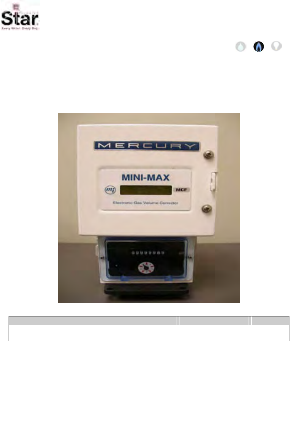
MTU Instruction
for Mini-Max Electronic Gas Volume Corrector
Purpose & Scope
This instruction provides a procedure for use in wiring and mounting a STAR MTU to a
Mercury Mini-Max Electronic Gas Volume Corrector that has been programmed to be
compatible with the STAR MTU. Please also refer to Publication 471-2000, General
Installation and Wiring Guidelines for general information covering the wiring and mounting
of STAR MTUs.
Parts Required
Item Part Number Quantity
Gas Bracket Direct Mount MTU for use with the Mini-Max. 501-8150R or 501-
8150RR 1
Tools Required
• 5/32” narrow-blade, slotted (flat-blade)
screwdriver
• Phillips screwdriver
• 8” adjustable wrench.
• Wire cutter/stripper
Also see Publication 471-2000, General
Installation and Wiring Guidelines for a
complete list of recommended tools and
supplies for MTU Installation.
471-2020 - 2/28/2006
Page 91
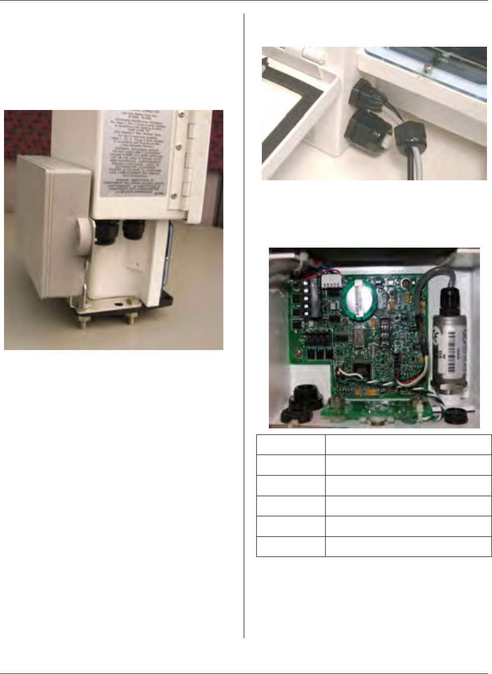
MTU Instruction
for Mini-Max Electronic Gas Volume Corrector
Installation Procedure
Step 1 – Attach the MTU Bracket
Assembly onto the top of the Mini-Max
gasket and to the gas meter by removing
the appropriate hardware from the gas
meter and then reinstalling the hardware.
Step 2 – If both the corrected and
uncorrected readings from the Mini-Max
will be monitored, there will be two wires
coming out of the back of the 501-
8150RR MTU thru a notch in the bracket.
One wire is black and connects to port 1
of the MTU. This will be used for the
Corrected Reading. The gray wire
connects to port 2 of the MTU and will be
used for the Uncorrected reading.
If only the corrected reading will be
monitored, the 501-8150R MTU will have
only a single black wire which is used for
the corrected reading.
Step 3 – Remove the smaller strain relief
connector nut completely and place it
over the wire(s). Push the wire(s) into the
connector leaving approximately 4 to 5
inches of wire inside the unit. Place the
connector cap back onto the stain relief
and hand tighten.
Step 4 – Remove the terminal block TB1
from the circuit board. This will unplug by
pulling it straight out. The top terminal
(Terminal 1) is common.
Terminal Signal
1 Common
2 Corrected Pulse Output
3 Uncorrected Pulse Output
4 Alarm (-)
5 Alarm (+)
Step 5 – Strip ¼ inch of insulation off of
each MTU wire. Insert the black and
white wires into Terminal 1 (Common).
Tighten the screw on the side. Make sure
the wires are captured securely. Insert
Page 92
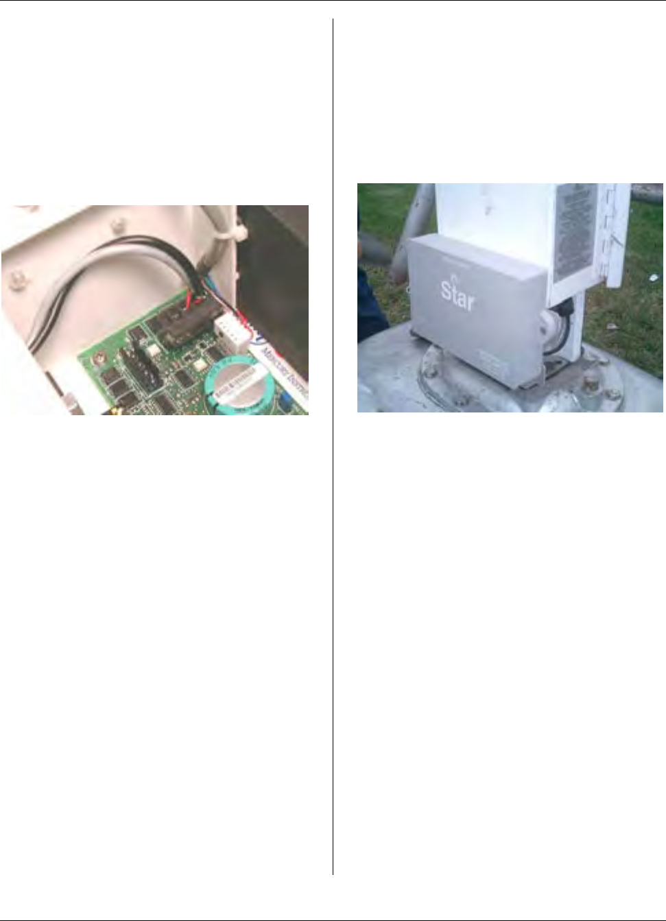
MTU Instruction
for Mini-Max Electronic Gas Volume Corrector
the red wire from the black cable into
Terminal 2. Tighten the screw on the
side. Insert the red wire from the gray
cable (if used) into Terminal 3. Tighten
the screw on the side.
Step 6 – Press the terminal block back
onto the connector on the circuit board.
Make sure that it seats fully. This
completes the wiring of the MTU.
Mini-Max Configuration
Notes
The Mini-Max must be properly
programmed to have the corrected and
uncorrected outputs available on TB1.
Per the Mini-Max Operator’s Guide:
• Item No. 093 should be set to
Code 0. This will select the
Corrected output to be on for TB1
slot 2.
• Item No. 094 needs to be
programmed to Code 2 in order to
select the Uncorrected output to be
on TB1 slot 3.
• Item 096 and 097 should be set to
Code 2, which will set the display
to 6 digits and match the reading
length stored in the MTU.
• Item No. 115 should be left at the
default of 0 which will give a pulse
width of 0.0625 Sec.
• Item No. 090 and 092 need to be
programmed to match the scaling
in the MTU. Ex. Code 1 = CU FT x
10; Code 2 = CU FT x 100.
Other settings may be needed for the
Mini-max to operate correctly. See the
Mini-Max Operators Guide for further
instructions.
Page 93

MTU Instruction
for Mini-Max Electronic Gas Volume Corrector
Intentionally Left Blank
Page 94

MTU Instruction
for Sprague Model 175 Gas Meters
Purpose & Scope
This instruction provides a procedure for installing a STAR indirect-mount MTU on a
Sprague Model 175 (flat-face) Gas Meter.
Parts Required
Item Part Number Quantity
MTU, Indirect Mount, for Sprague 175 501-6327H,
501-6327HH or
501-6327HD5
1
10-24 x 3/8” Slotted, Fillister Head Machine Screw 069-102412HA 2
Wheel/Magnet Assembly 109-7126A 1
MTU spacer for pipe or bar mount 056-5155K 1
18″ heavy-duty UV-resistant tie wrap 067-0030 2
10-32 x 1½″ pan head machine screw 069-103248CS 2
10-32 nut, stainless steel 069-3011 2
#10 7/16” flat washer, stainless steel 069-3004 2
471-2021 - 2/28/2006
Page 95
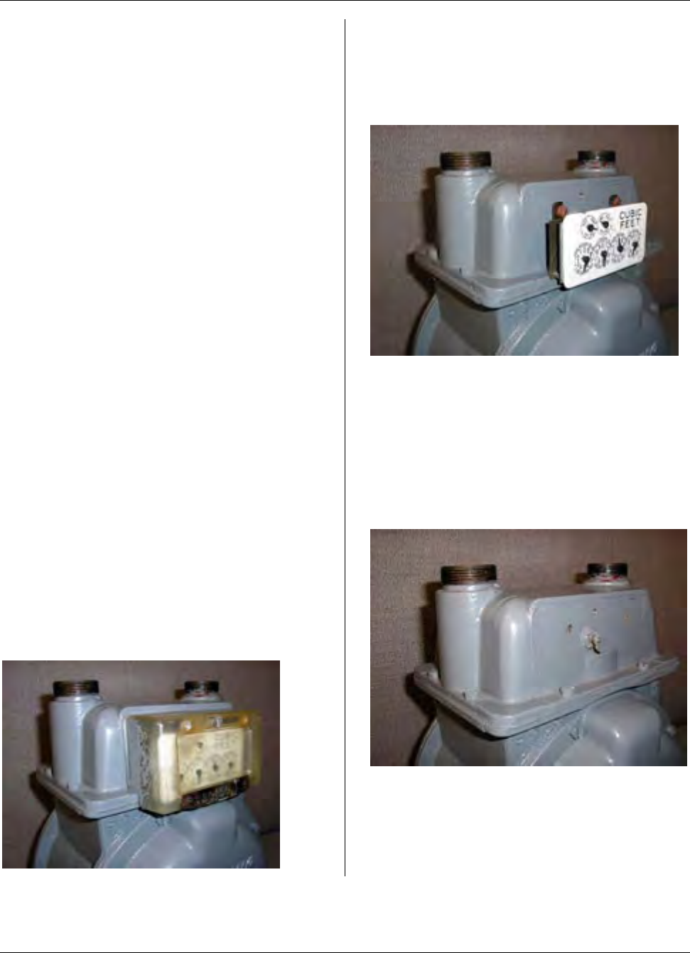
MTU Instruction
for Sprague Model 175 Gas Meters
Tools Required
To mount the MTU to these meters, you
will need the following tools and
equipment:
• Small, diagonal plastic cutting
pliers
• 7/16″ boxwrench
• Safety goggles
• #1 and #2 Phillips screwdrivers
• #1 and #2 Slotted screwdrivers
See Publication 471-2000, General
Installation and Wiring Guidelines for a
complete list of recommended tools and
supplies for MTU Installation.
Installation Procedure
Installing the Sensor Assembly
Before installing the Sensor Assembly,
anti-tamper, safety, and security
hardware must be removed from the clear
register cover.
Step 1 – Remove the clear index cover
from the meter by removing the screw
that holds it. The clear index cover and
the index cover screw will be reused.
Clean and inspect these items and set
them aside until needed. Replace if
damaged.
Step 2 – Remove the index by removing
the two screws that hold it to the meter.
Set the index aside until later. The
screws that held the index to the meter
can be discarded.
Step 3 – Remove the drive foot from the
meter drive shaft by unthreading it
counterclockwise. The drive foot will not
be reused and can be discarded. Then,
thread the magnet wheel clockwise onto
the shaft. Tighten the magnet wheel until
snug to the end of the threads on the
drive shaft.
Page 96
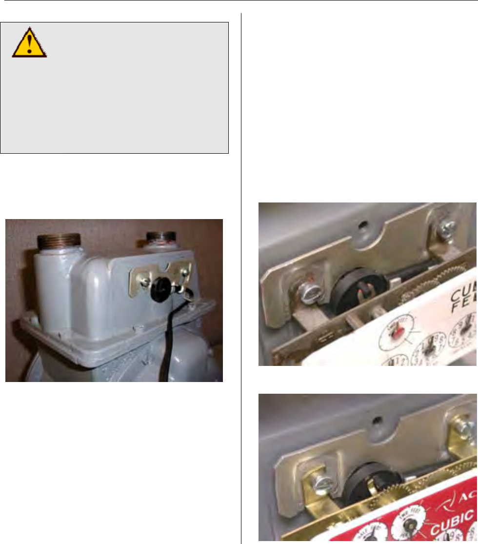
MTU Instruction
for Sprague Model 175 Gas Meters
CAUTION!
Be careful not to cross-thread
the magnet wheel when
installing it on the meter drive
shaft. Cross-threading can
cause misalignment of the
magnet wheel which in turn
can cause binding or erratic
performance.
Step 4 – Start the two 10-24 x 3/8”
machine screws into the index mounting
holes. Thread each screw in
approximately one full turn.
Step 5 – Attach the sensor to the meter
by positioning the keyhole-shaped slots of
the sensor bracket over the index
mounting screws as shown here. Route
the sensor wire through the slot at the
bottom right-hand corner of the sensor
bracket and back to the left under the
magnet wheel so that it does not interfere
with the magnet wheel or the index gears.
Step 6 – Replace the index by hooking
the two tabs on the index behind the
heads of the index mounting screws.
Insure that the drive foot on the index will
be driven by the pin on the magnet wheel
as it rotates. Several styles of indexes
and index drive mechanisms may be
encountered. Use the photos below as a
guide. Note that on indexes with a slotted
drive foot, it is intended that the pin on the
magnet wheel engages the slot on the
drive foot.
Brass Index with Slotted Drive Foot
Brass Index with Offset Drive Foot
Page 97
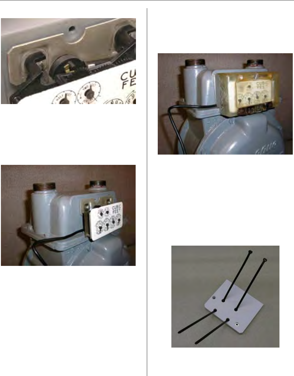
MTU Instruction
for Sprague Model 175 Gas Meters
Plastic Index with Metal Drive Foot
Step 7 – Route the sensor wire so that it
does not interfere with the magnet wheel
or the index gears. Hand tighten index
mounting screws. Gently move the 2-foot
hand to check for some free play to
insure that the register is not binding up.
Step 8 – Next, create an exit notch for the
sensor wire by cutting away a small piece
of the corner where the left hand edge of
the clear index cover meets the ridge at
the bottom of the meter head.
Step 9 – Secure the clear index cover to
the meter using the screw that originally
held it. Tighten the index cover screw.
Step 10 - Replace any anti-tamper,
safety, or security hardware onto the
clear index cover as required.
Bar Mounting the MTU
Step 1 - Thread the tie-wraps into the
MTU spacer as shown here.
Step 2 - Attach the spacer to the MTU
using the provided screws and washers.
Tighten the screws to 12 to 15 in-lb. On a
Page 98
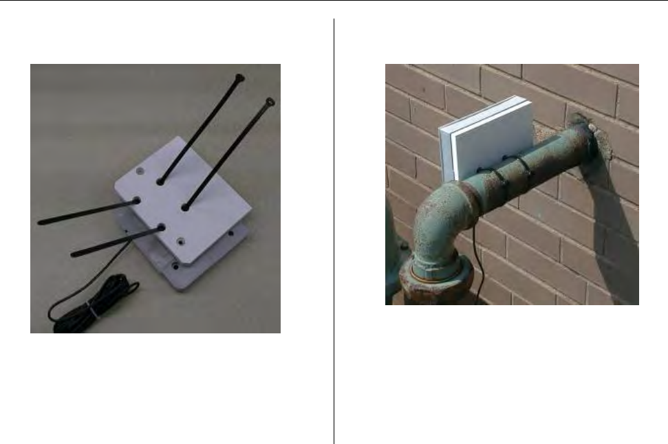
MTU Instruction
for Sprague Model 175 Gas Meters
standard drill driver with 0 to 24 torque
settings, this is typically the #10 setting.
Step 3 - Wrap the tie wraps around the
bar as needed, pulling the ties around
(through the spacer plate) as they are
tightened.
Step 4 - Adjust the MTU as needed and
pull the tie wraps tight.
Step 5 - Trim off the excess tie wrap,
leaving about a ½” tab.
Step 6 – Once Installation is complete,
program the MTU using the STAR
Programmer Software and your MTU
Programmer.
Page 99

MTU Instruction
for Sprague Model 175 Gas Meters
Intentionally Left Blank
Page 100
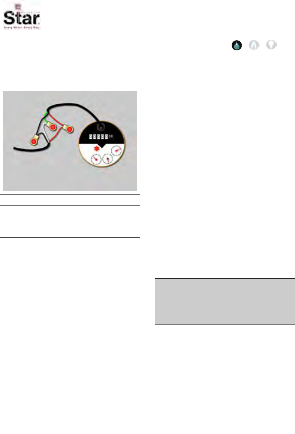
MTU Instruction
for Metron-Farnier Water Meters
Purpose & Scope
This instruction provides wiring information for connecting a STAR MTU to a Metron-
Farnier Water Meter equipped with an OER register.
Metron OER Register
MTU Cable OER Cable
Red R (Red)
Black B (Black)
White G (Green)
Supplies and Tools Required
See Publication 471-2000, General
Installation and Wiring Guidelines for a
complete list of recommended tools and
supplies for MTU Installation.
Application Notes
• The 5-digit Metron OER register must
be configured for an additional trailing
zero for proper operation with STAR
MTUs.
Installation Procedure
Step 1 - Select a mounting location for
the MTU that will allow optimum signal
transmission, and install any needed
wiring. Be sure to follow all General
Installation and Wiring Guidelines as
outlined in Publication 471-2000.
Step 2 – Select the wiring diagram that
applies to the meter you are connecting
and make the appropriate wiring
connections.
a. Direct Wiring to Meter - MTU
wiring is supplied stripped to a
standard length that fits water
meters with screw terminals.
Simply wrap the wires around the
screw terminal and tighten the
screw. It is recommended that the
screws be tightened to no more
than 4 – 5 in-lbs. Overtightening
the screw can stress and possibly
fracture the wire.
b. Water Meter with Integral Cable -
If the water meter is supplied with
an integral cable and a cable-to-
cable splice is necessary, use a
gel-filled wire splice designed for
outdoor (moisture applications) to
seal the individual connections.
Note: When connecting a dual port MTU
to a compound meter, connect port 1
(black jacket) to the primary, or high-flow
register and port 2 (grey jacket) to the
secondary or low-flow register.
Step 3 – Make a final visual check of the
wiring from the MTU to the meter register.
Verify that the cable routing is neat,
secure and professional.
Step 4 – Once installation and wiring are
complete, program the MTU using the
STAR Programmer Software and your
MTU Programmer.
471-2022 - 2/28/2006
Page 101

MTU Instruction
for Metron-Farnier Water Meters
Intentionally Left Blank
Page 102
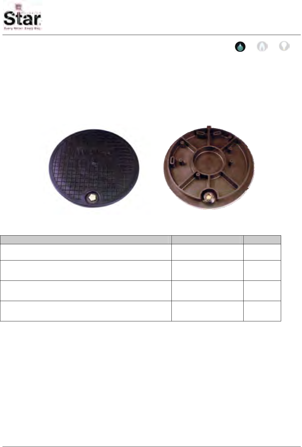
MTU Instruction
for Nicor Composite Pit Lids
Purpose & Scope
This instruction provides a procedure for mounting a STAR MTU to a Nicor Type A, Type
C or Type X composite pit lid. This procedure covers the mounting of an Original Flatpak
STAR MTU or the New Flatpak STAR MTU to these pit lids. This procedure does not
detail the wiring of the MTU to the meter inside of the pit. Please refer to Publication 471-
2000, General Installation and Wiring Guidelines in addition to any meter specific MTU
installation and programming instructions.
Parts Required
Item Part Number Quantity
MTU As required for installed
meter 1
#8 x 1-1/4” Truss Head Phillips Sheet Metal Screw, 18-8
stainless steel (McMaster # 93406A201) 2 per Original
Style MTU
installation
Spacers (for pit lid mounting of New Style Flatpak MTUs) 056-8150S 2 per New
Style MTU
installation
#8 x 2” Phillips Pan Head Sheet Metal Screw, 18-8 stainless
steel (McMaster #92470A205) 2 per New
Style MTU
installation
Tools Required
To mount the MTU to these pit lids, you
will need the following tools and
equipment:
• Safety goggles
• #3 Phillips driver bit
• Cordless Drill 3/8”, variable speed,
with adjustable torque settings.
Note on setting the torque range: On a
drill-driver that has about 20 settings
(positions), set the adjustment to #6. Use
the lower speed range of the drill-driver.
This should amount to approximately 8 in-
lbs of torque. Reference the operating
instructions for your particular drill to
more accurately determine what setting to
use to achieve a torque range of
approximately 8 in-lbs.
471-2023 - 4/3/2006
Page 103
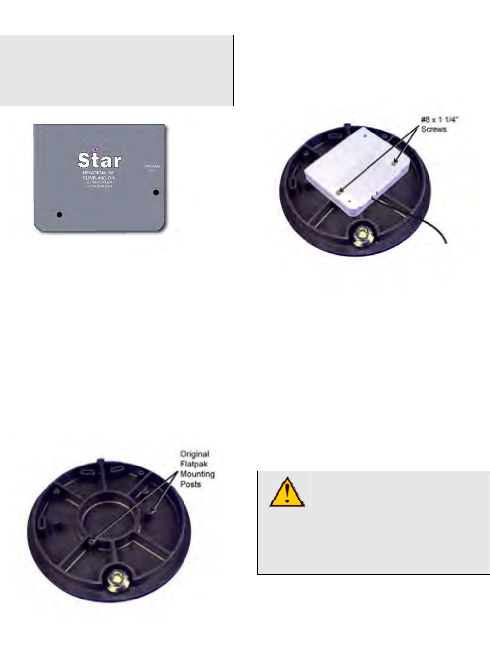
MTU Instruction
for Nicor Composite Pit Lids
Installation Procedure
NOTE: The Nicor Type A, Type C and
Type X lids differ only slightly in their rim
and latching mechanism. STAR MTUs
can be mounted to either a Type A, Type
C or a Type X lid using this procedure.
Mounting an Original Flatpak STAR
MTU to a Nicor pit lid.
Step 1 – Place the pit lid top down on a
solid surface, positioning the metal latch
mechanism nearest to you as shown in
the photo below.
Step 2 – Note the mounting posts on the
bottom of the pit lid. Several posts are
provided for mounting a variety of
equipment. The posts used for mounting
an Original Flatpak STAR MTU are
highlighted in the photo below.
Step 3 – Position the MTU face-down on
the bottom surface of the pit lid. Place 2
stainless sheet metal screws through the
2 recessed mounting holes as shown,
and guide the screws into the holes on
the designated mounting posts.
Step 4 - Torque screws to approximately
8 in-lbs. MTU should be snug and flush to
the surface of the pit lid.
Step 5 – Wire the MTU to the meter,
making sure that the wire is routed so that
it does not become pinched when the lid
is closed.
Step 6 - Installation is now complete. You
can now proceed to program the MTU
using the STAR Programmer Software
and your MTU Programmer.
CAUTION!
Be sure to follow all General
Guidelines outlined in
Publication 471-2000 along
with the specific wiring
instructions for the meter
being used.
Page 104
MTU Instruction
for Nicor Composite Pit Lids
Mounting a New Flatpak STAR MTU to
a Nicor pit lid.
Step 1 – Place the pit lid top down on a
solid surface, positioning the metal latch
mechanism nearest to you as shown in
the photo below.
Step 2 – Note the mounting posts on the
bottom of the pit lid. Several posts are
provided for mounting a variety of
equipment. The posts used for mounting
a New Flatpak STAR MTU are
highlighted in the photo below.
Step 3 – Position the MTU face-down on
the bottom surface of the pit lid. Place
plastic spacers under the mounting lugs
on the MTU as shown below.
Step 4 - Place 2 stainless sheet metal
screws through the 2 mounting holes and
the spacers, and guide the screws into
the holes on the designated mounting
posts.
Step 5 – Torque screws to approximately
8 in-lbs. MTU should be snug and flush to
the surface of the pit lid.
Step 6 – Wire the MTU to the meter,
making sure that the wire is routed so that
it does not become pinched when the lid
is closed.
Step 7 - Installation is now complete. You
can now proceed to program the MTU
using the STAR Programmer Software
and your MTU Programmer.
Page 105

MTU Instruction
for Nicor Composite Pit Lids
Intentionally Left Blank
Page 106
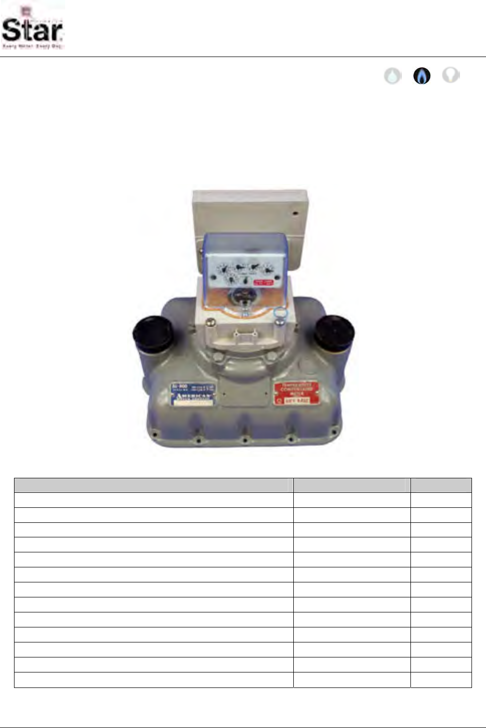
MTU Instruction
for American Model AL800-AL5000 Gas Meters
Purpose & Scope
This instruction provides a procedure for use in installing a Hexagram STAR MTU and
Large Meter Pulser on an American Model AL800-AL5000 Industrial & Commercial
Diaphragm Gas Meters. Please also refer to Publication 471-2000, General Installation
and Wiring Guidelines for general information covering the wiring and mounting of STAR
MTUs.
Parts Required
Item Part Number Quantity
#18-18 x 2.6” slotted round head bolt, stainless 069-181880DS 4
#12-24 x 2-¼” slotted fillister head screw, stainless 069-122472HS 2
American index cover gasket 066-0033 1
Security cups 066-0336 2
Security caps 066-0337 2
2-pin drive disk 056-11585C 1
Tall, 2-slot coupler with magnet 056-11585B 1
Shaft, standard 056-5155D 1
Adapter, 5155 style MTU enclosure to pulser body 056-11585D 1
¼-20 x 1-½” Phillips pan head machine screw, stainless 069-142048AS 2
¼-20 nylock nut, stainless 069-3222 2
#8-18 x ½” Phillips pan head thread forming screw, stainless 069-080016A4S 2
MTU/Pulser Assembly (or separate MTU and pulser) per project 1
471-2026 - 7/18/2007
Page 107
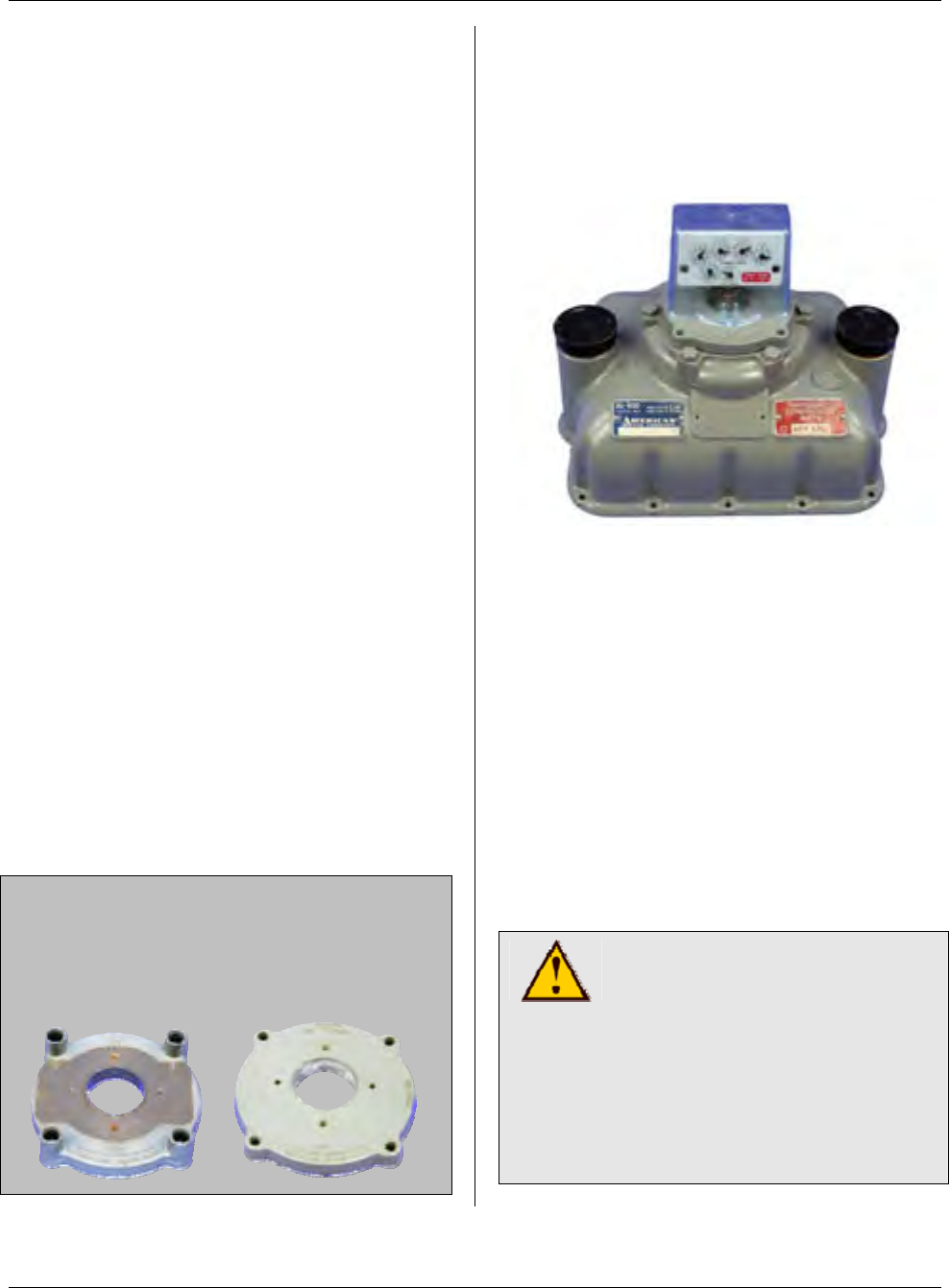
MTU Instruction
for American Model AL800-AL5000 Gas Meters
Tools Required
• Screwdriver, #2 Phillips
• Screwdriver, 3/8” slotted (flat-
blade)
• 7/16” box wrench
• 18-18 blind-hole (bottoming) tap
and mating size T-handle
• 12-24 blind-hole (bottoming) tap
and mating size T-handle
• Canned compressed air
Also see Publication 471-2000, General
Installation and Wiring Guidelines for a
complete list of recommended tools and
supplies for MTU Installation.
Installation Procedure
There are two parts to this procedure.
First, the pulser must be mounted to the
meter. Once this is complete, you can
mount the MTU remotely or directly on
the pulser using the adapter provided. If
you are mounting the MTU on the pulser,
it can be mounted at either the front or
back of the meter.
Step 1 – If necessary, remove tamper
seals from any of the 4 screws that
secure the index base plate and the two
screws that secure the index box to the
base plate.
Note: If the index base plate has integral
security towers like the one on the left
below, it must be replaced with the flat
style index base plate like the one shown
on the right.
Step 2- Loosen and remove the four
screws securing the index base plate
assembly to the meter. You may discard
these screws as they will not be re-used.
Remove the index box and base plate
assembly from the top of the meter.
Step 3 – Disassemble the index box from
the base plate by removing the two
screws that secure the index box to the
base plate. You may discard these
screws as they will not be re-used.
Step 4 – If the index box and/or base
plate mounting screws were difficult to
remove, the threads in the meter head
may need to be cleaned out before
installing the new hardware that will retain
the index base plate, the pulser and the
index box. Use the blind-hole taps to
carefully clean the threads of the index
box and base plate mounting holes.
CAUTION!
The index base plate
mounting holes use a #18-18
thread. The index box
mounting holes use a #12-24
thread. Be sure to use the
proper tap for each hole.
Using the wrong tap will result
in damage to the meter head.
Page 108

MTU Instruction
for American Model AL800-AL5000 Gas Meters
After using the tap, blow out the holes
with compressed (canned) air.
Step 5 – Place the index base plate onto
the head of the meter. Align the index
base plate with the index plate mounting
holes on the meter head and the large
opening in the base plate is centered over
the drive mechanism.
Step 6 – Break out the tab for either the
front or rear wire exit on the bottom edge
of the pulser body, depending on how you
plan to mount the MTU. (See the
illustration below.)
Step 7 – Assemble the couplers and
shaft to the pulser body as shown in the
illustration below. Ensure that the
magnet is mounted on the Tall Coupler,
and that the retaining shaft is securely
snapped into both the Tall Coupler and
the 2-Pin Drive Disk.
Step 8 – Place the pulser on the index
base plate, aligning the bottom coupler on
the pulser with the wiggler on the meter.
Align the corner mounting holes on the
pulser with the mounting holes on the
index base plate.
Page 109
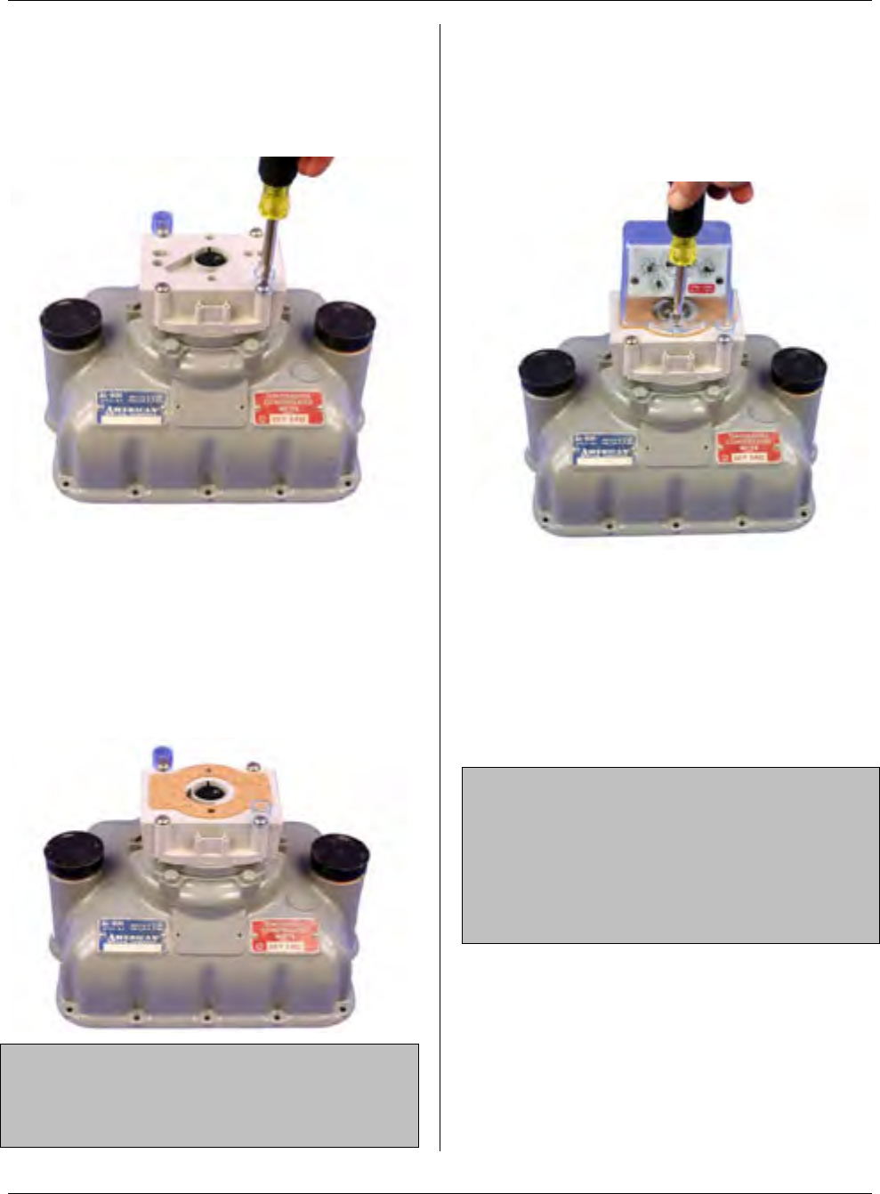
MTU Instruction
for American Model AL800-AL5000 Gas Meters
Step 9 – Fasten the pulser to the meter
body using the four #18-18 x 2.6” slotted,
stainless steel round head bolts provided.
Install security cups, if desired, as shown
below.
Step 10 – If the index box assembly has
a silicone gasket applied around its
bottom edge and that gasket is in good
shape, you can discard the index cover
gasket supplied with the pulser and skip
to Step 11. Otherwise, place the index
cover gasket on the pulser, aligning the
gasket as shown below.
NOTE: When using the cork gasket
supplied with the pulser, be sure that the
bottom edge of the index box is clean and
free of any silicone and/or dirt particles.
Step 11 – Place the index box assembly
on the pulser, aligning the the drive foot
with the two-pin drive disk. Fasten the
index box to the meter with the two #12-
24 x 2-¼” slotted, stainless steel fillister
head screws provided.
Installation of the pulser is now complete.
If you will be remotely mounting the MTU,
refer to Publication 471-2000, General
Installation and Wiring Guidelines for
general information covering the wiring
and mounting of STAR MTUs. Continue
to Step 12 if you will be mounting the
MTU to the pulser body.
NOTE: The pulser and MTU can be
supplied pre-wired or as separate
assemblies. If provided as separate
components, connect the three wires in
the pulser cable (red, black, and white) to
the corresponding wires in the MTU
cable.
Page 110
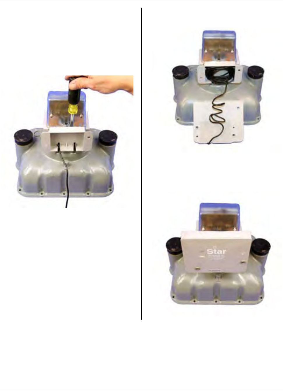
MTU Instruction
for American Model AL800-AL5000 Gas Meters
Step 12 – Continue here to mount the
MTU to the pulser using the adaptor
provided. Begin by positioning the
adaptor on the back (or front) of the
pulser body and attach it using the two
#8-18 x ½” Phillips pan head thread
forming screws provided, as shown
below.
Step 13 – Bundle the excess wire into the
compartment on the adaptor.
Step 14 - Mount the MTU to the adaptor
using the two ¼-20 x 1-½” Phillips pan
head machine screws and the ¼-20
nylock nuts.
Page 111
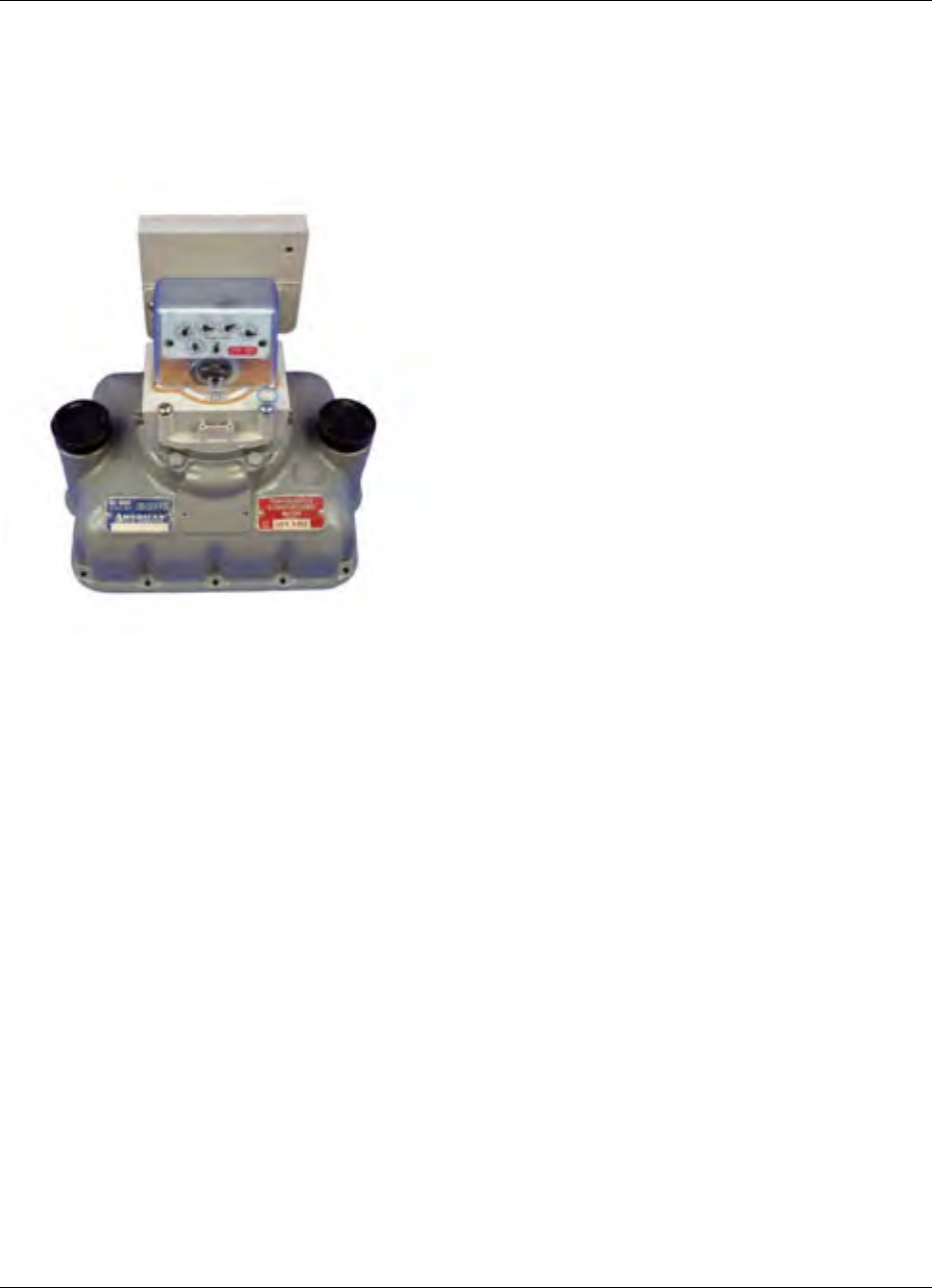
MTU Instruction
for American Model AL800-AL5000 Gas Meters
Step 15 – Installation is now complete.
Program the MTU using the STAR
Programmer Software and your Field
Programmer.
Page 112
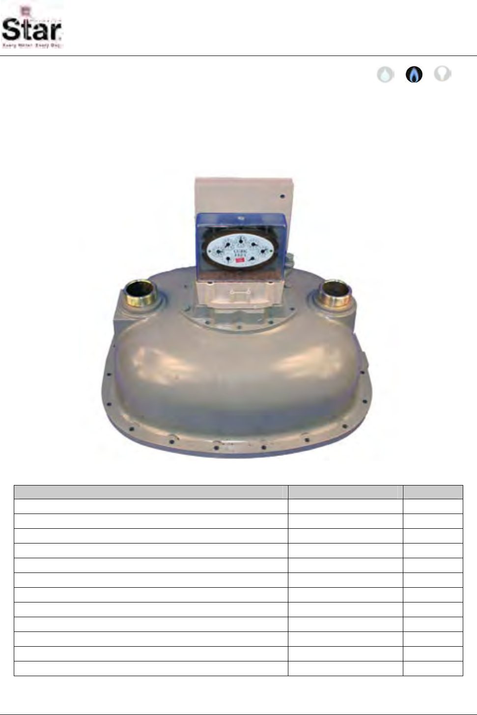
MTU Instruction
for Rockwell/Equimeter Commercial Gas Meters
Purpose & Scope
This instruction provides a procedure for use in installing a Hexagram STAR MTU and
Large Meter Pulser on a Rockwell/Equimeter Model 750-10000 Intermediate or Large
Capacity Diaphragm Gas Meters. Please also refer to Publication 471-2000, General
Installation and Wiring Guidelines for general information covering the wiring and mounting
of STAR MTUs.
Parts Required
Item Part Number Quantity
5/16 -18 x 2 1/4” slotted fillister head bolt, stainless 069-561872HS 2
5/16 -18 x 3” slotted fillister head bolt, stainless 069-561896HS 2
Gasket, large pulser, upper, Rockwell Index Cover 066-11585B 1
Gasket, large pulser, lower, standard 066-11585A 1
Standard coupler – with magnet 056-11703B 1
Tall, 2-slot coupler 056-11585B 1
Shaft, standard 056-5155D 1
Adapter, 5155 style MTU enclosure to pulser body 056-11585D 1
¼-20 x 1-½” Phillips pan head machine screw, stainless 069-142048AS 2
¼-20 nylock nut, stainless 069-3222 2
#8-18 x ½” Phillips pan head thread forming screw, stainless 069-080016A4S 2
MTU/Pulser Assembly (or separate MTU and pulser) per project 1
471-2027 - 7/18/2007
Page 113
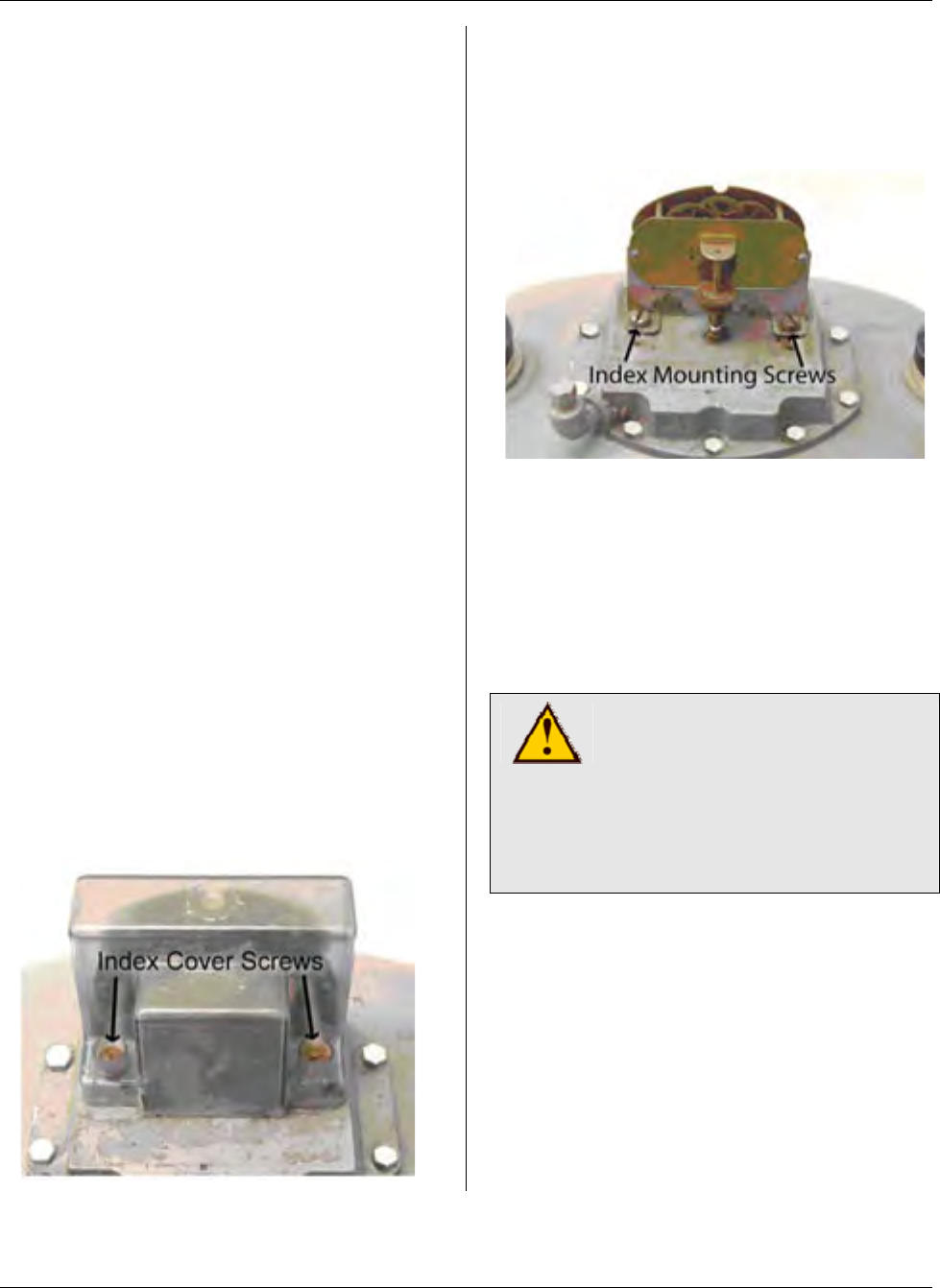
MTU Instruction
for Rockwell/Equimeter Commercial Gas Meters
Tools Required
• Screwdriver, #2 Phillips
• Screwdriver, 3/8” slotted (flat-
blade)
• 7/16” box wrench
• 5/16-18 blind-hole (bottoming) tap
and mating size T-handle
• Canned compressed air
Also see Publication 471-2000, General
Installation and Wiring Guidelines for a
complete list of recommended tools and
supplies for MTU Installation.
Installation Procedure
There are two parts to this procedure.
First, the pulser must be mounted to the
meter. Once this is complete, you can
mount the MTU remotely or directly on
the pulser using the adapter provided. If
you are mounting the MTU on the pulser,
it can be mounted at either the front or
back of the meter.
Step 1 – If necessary, remove tamper
seals that cover the index cover screws.
Loosen and remove the screws securing
the index cover. You may discard these
screws as they will not be re-used.
Remove the index cover and set it aside.
Step 2 – Loosen and remove the screws
securing the index to the index plate. You
may discard these screws as they will not
be re-used. Next, remove the index and
set it aside.
Step 3 – If the index cover screws and
index mounting screws were difficult to
remove, the threads in the index plate
may need to be cleaned out before
installing the pulser assembly. Use the
blind-hole tap to carefully clean the
threads of the four 5/16” holes. Blow out
the holes with compressed (canned) air.
CAUTION!
The index base plate
mounting holes use a 5/16-18
thread. Be sure to use the
proper tap. Using a tap other
than a 5/16-18 tap will result in
damage to the meter head.
Page 114
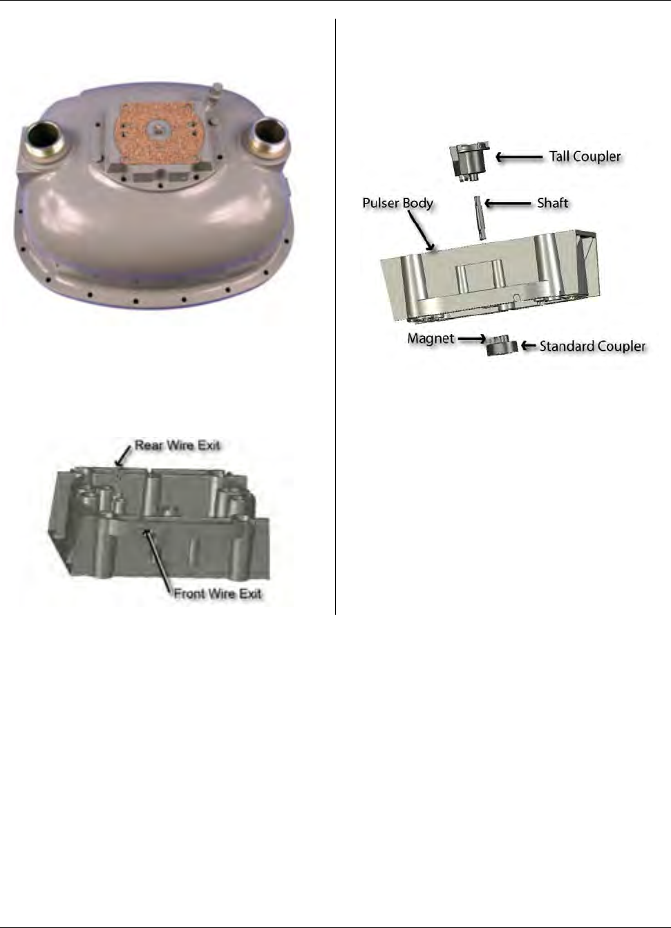
MTU Instruction
for Rockwell/Equimeter Commercial Gas Meters
Step 4 – Position the lower gasket on the
meter as shown in the illustration below.
Step 5 – Break out the tab for either the
front or rear wire exit on the bottom edge
of the pulser body, depending on how you
plan to mount the MTU. (See the
illustration below.)
Step 6 – Assemble the couplers and
shaft to the pulser body as shown in the
illustration below. Ensure that the
magnet is mounted on the Standard
Coupler, and that the retaining shaft is
securely snapped into both couplers.
Page 115
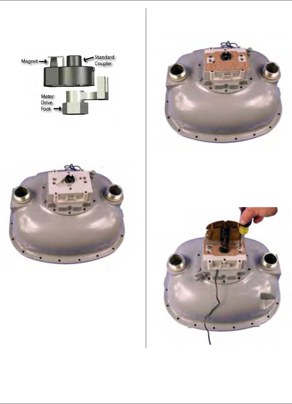
MTU Instruction
for Rockwell/Equimeter Commercial Gas Meters
Step 7 – Place the pulser on the meter,
aligning the lower coupler so that it will
engage the fork portion of the meter drive
foot as shown below.
Ensure that the pulser body sits properly
on the gasket and that the wire is routed
through the wire exit notch.
Step 8 – Next, place the upper gasket on
top of the pulser as shown in the
illustration below.
Step 9 – Mount the index onto the pulser
using the 5/16 -18 x 2 1/4” slotted fillister
head bolts provided, as shown in the
illustration below. Ensure that the drive
foot on the index engages with the slot in
the top of the tall coupler.
Page 116
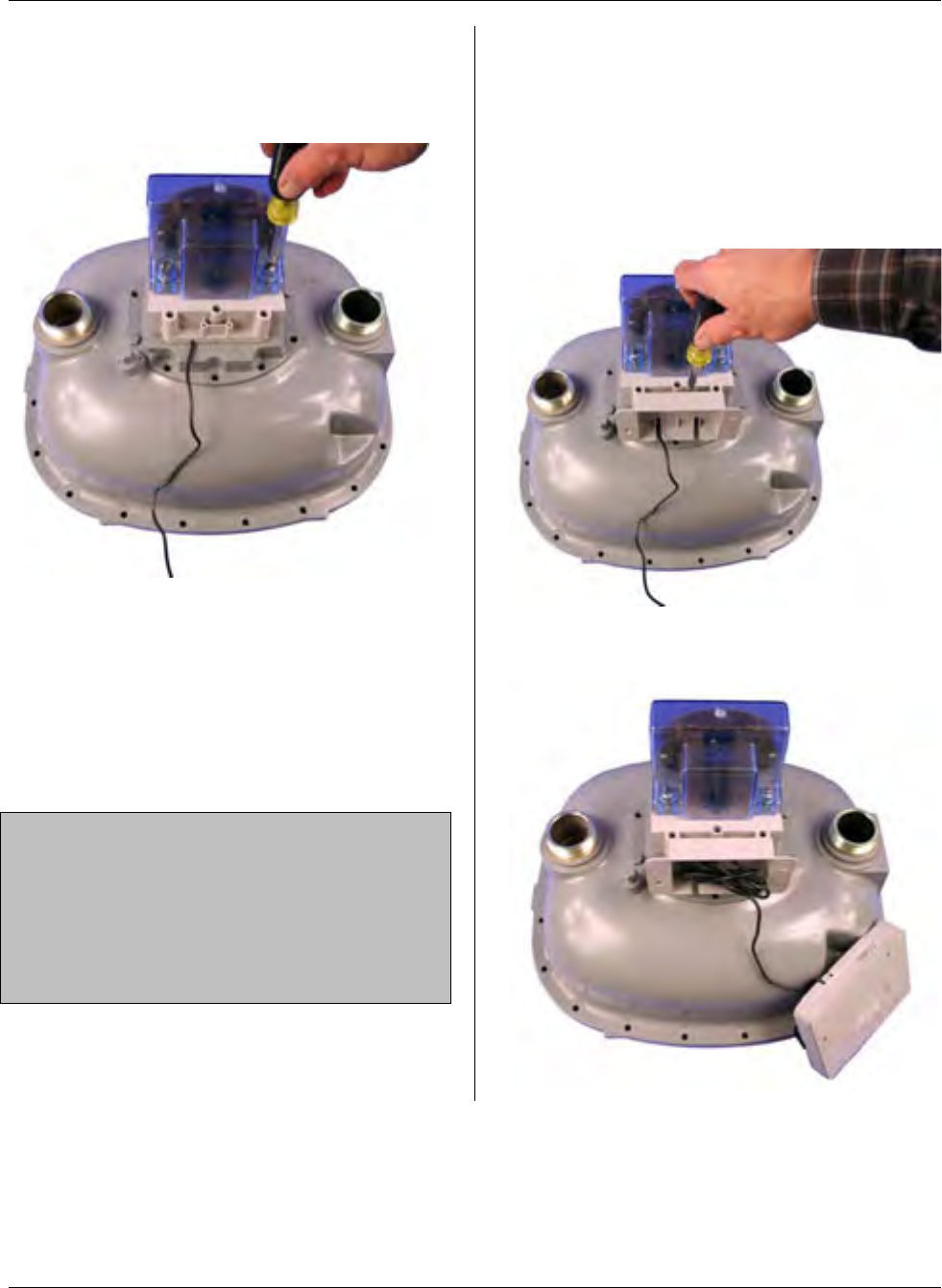
MTU Instruction
for Rockwell/Equimeter Commercial Gas Meters
Step 10 – Next, mount the index cover
onto the pulser using the 5/16 -18 x 3”
slotted fillister head bolts provided, as
shown in the illustration below.
Installation of the pulser is now complete.
If you will be remotely mounting the MTU,
refer to Publication 471-2000, General
Installation and Wiring Guidelines for
general information covering the wiring
and mounting of STAR MTUs. Continue
to Step 11 if you will be mounting the
MTU to the pulser body.
NOTE: The pulser and MTU can be
supplied pre-wired or as separate
assemblies. If provided as separate
components, connect the three wires in
the pulser cable (red, black, and white) to
the corresponding wires in the MTU
cable.
Step 11 – Continue here to mount the
MTU to the pulser using the adaptor
provided. Begin by positioning the
adaptor on the back (or front) of the
pulser body and attach it using the two
#8-18 x ½” Phillips pan head thread
forming screws provided, as shown
below.
Step 12 – Bundle the excess wire into the
compartment on the adaptor.
Page 117
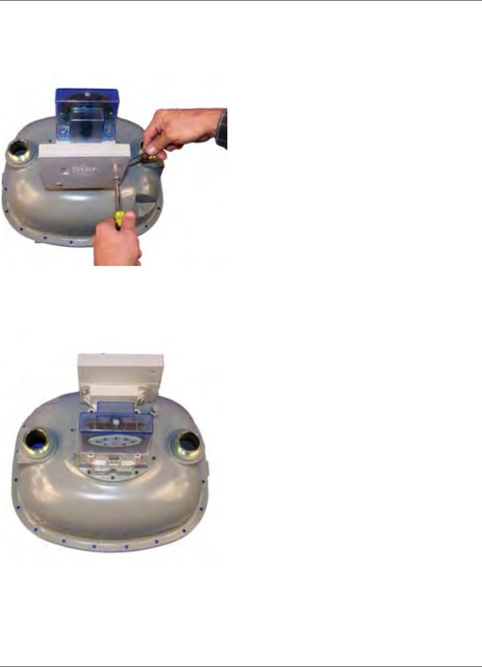
MTU Instruction
for Rockwell/Equimeter Commercial Gas Meters
Step 13 – Mount the MTU to the adaptor
using the two ¼-20 x 1-½” Phillips pan
head machine screws and the ¼-20
nylock nuts.
Step 14 – Installation is now complete.
Program the MTU using the STAR
Programmer Software and your Field
Programmer.
Page 118
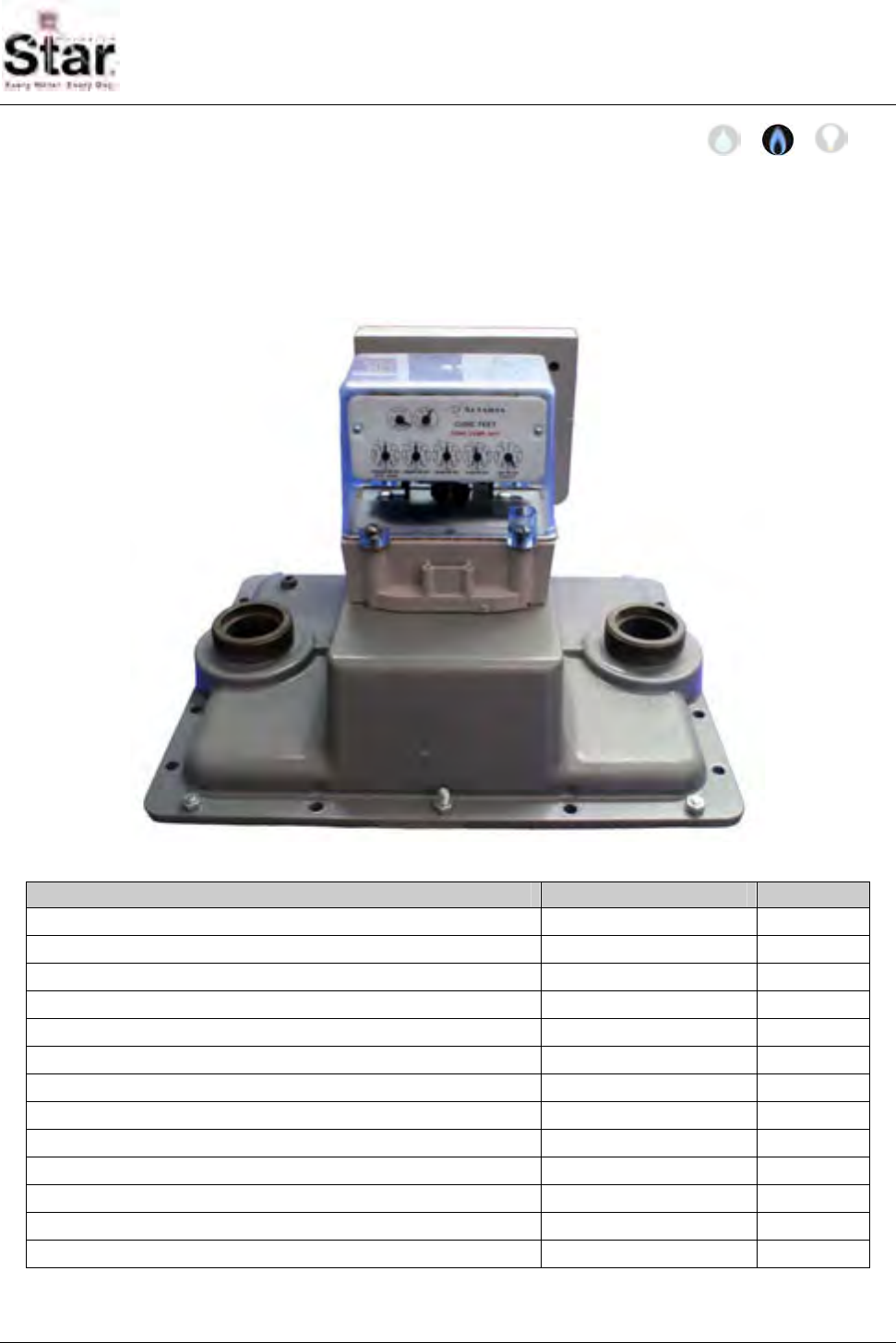
MTU Instruction
for Sprague/Actaris 675A, 800A and 1000A Gas Meters
Purpose & Scope
This instruction provides a procedure for use in installing a Hexagram STAR MTU and
Large Meter Pulser on an Sprague/Actaris Model 675A, 800A or 1000A Industrial &
Commercial Diaphragm Gas Meters. Please also refer to Publication 471-2000, General
Installation and Wiring Guidelines for general information covering the wiring and mounting
of STAR MTUs.
Parts Required
Item Part Number Quantity
¼-20 x 2-1/4” slotted fillister head bolt, stainless 069-142072HS 6
Sprague index cover gasket 066-0034 1
Gasket, large pulser, lower, standard 066-11585A 1
Standard coupler - with magnet 056-11703B 1
Tall, 2-slot coupler 056-11585B 1
Shaft, standard 056-5155D 1
Adapter, 5155 style MTU enclosure to pulser body 056-11585D 1
¼-20 x 1-½” Phillips pan head machine screw, stainless 069-142048AS 2
¼-20 nylock nut, stainless 069-3222 2
#8-18 x ½” Phillips pan head thread forming screw, stainless 069-080016A4S 2
MTU/Pulser Assembly (or separate MTU and pulser) per project 1
Shaft, extended 056-12466B 1
½” OD x ¼” L round nylon spacer 068-141608EX 2
471-2028P - 7/18/2007
Page 119
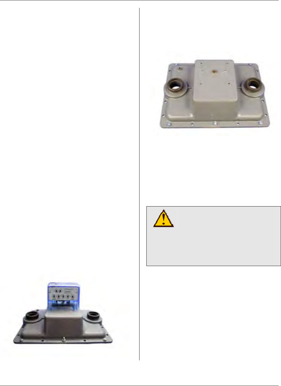
MTU Instruction
for Sprague/Actaris 675A, 800A and 1000A Gas Meters
Tools Required
• Screwdriver, #2 Phillips
• Screwdriver, 3/8” slotted (flat-
blade)
• 7/16” box wrench
• 1/4-20 blind-hole (bottoming) tap
and mating size T-handle
• Canned compressed air
Also see Publication 471-2000, General
Installation and Wiring Guidelines for a
complete list of recommended tools and
supplies for MTU Installation.
Installation Procedure
There are two parts to this procedure.
First, the pulser must be mounted to the
meter. Once this is complete, you can
mount the MTU remotely or directly on
the pulser using the adapter provided. If
you are mounting the MTU on the pulser,
it can be mounted at either the front or
back of the meter.
Step 1 – If necessary, remove tamper
seals from any of the four screws that
secure the index cover to the meter body.
Step 2- Loosen and remove the four
screws securing the index cover to the
meter. You may discard these screws as
they will not be re-used. Remove the
index cover from the top of the meter.
Step 3 – Remove the two screws
securing the index to the top of the meter.
You may discard these screws as they
will not be re-used. Remove the index
and set it aside.
Step 4 – If the index base plate mounting
screws were difficult to remove, the
threads in the meter head may need to be
cleaned out before installing the hardware
that will retain the index base plate, the
pulser and the index box. Use the blind-
hole tap to carefully clean the threads of
the index base plate mounting holes.
CAUTION!
The index base plate
mounting holes use a 1/4-20
thread. Be sure to use the
proper tap. Using a tap other
than a ¼-20 tap will result in
damage to the meter head.
After using the tap, blow out the holes
with compressed (canned) air.
Page 120
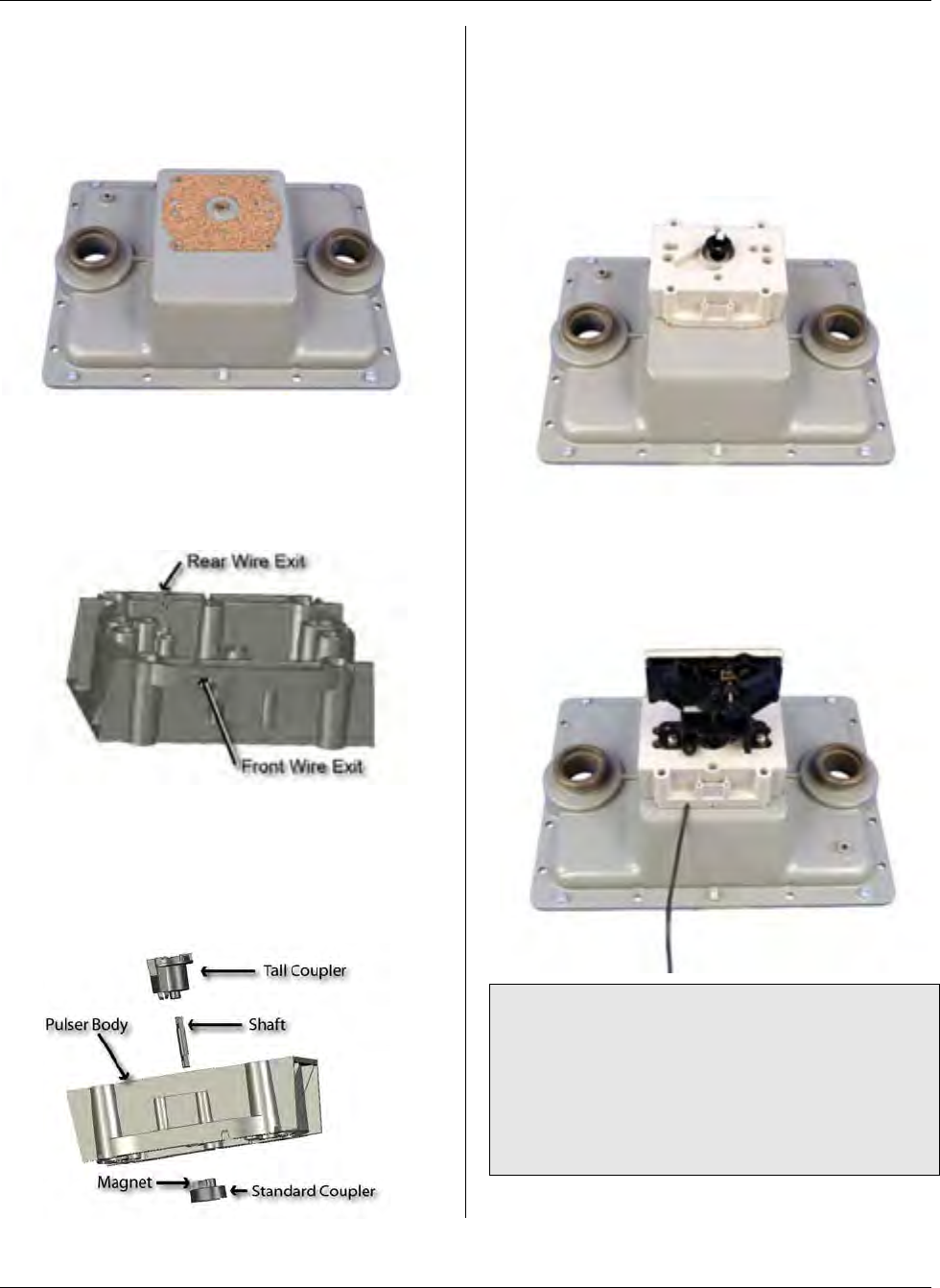
MTU Instruction
for Sprague/Actaris 675A, 800A and 1000A Gas Meters
Step 5 – Place the lower gasket onto the
meter, aligning it as shown to insure that
the openings for the index bolts and index
cover bolts match up with the threaded
holes on the top of the meter.
Step 6 – Break out the tab for either the
front or rear wire exit on the bottom edge
of the pulser body, depending on how you
plan to mount the MTU. (See the
illustration below.)
Step 7 – Assemble the couplers and
shaft to the pulser body as shown in the
illustration below. Ensure that the
magnet is mounted on the Standard
Coupler, and that the retaining shaft is
securely snapped into both couplers.
Step 8 – Place the pulser on the lower
gasket, aligning the bottom coupler on the
pulser with the wiggler on the meter.
Align the corner mounting holes on the
pulser with the mounting holes on the
index base plate.
Step 9 – Position the index on top of the
pulser, aligning the drive pin on the index
with the slot on the tall coupler. Ensure
that there is no binding.
Note: On some models, a ‘shorter’ index
may not allow sufficient clearance
between the tall coupler and the index. In
this case, replace the standard shaft with
the extended shaft and insert the nylon
spacers provided between the index and
the pulser body.
Page 121
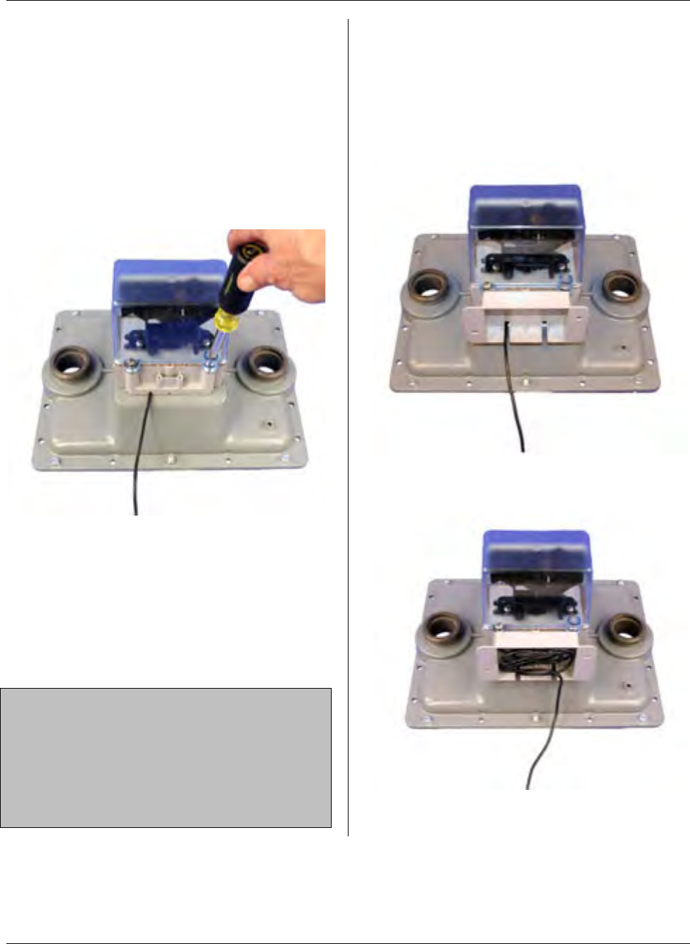
MTU Instruction
for Sprague/Actaris 675A, 800A and 1000A Gas Meters
Fasten the index to the meter with two of
the ¼-20 x 2-1/4” slotted, stainless steel
fillister head bolts provided.
Step 10 – Place the index cover gasket in
position on top of the pulser and then
place the index cover on the top of the
gasket. Fasten the index cover to the
meter using the four remaining ¼-20 x 2-
1/4” slotted, stainless steel fillister head
bolts.
Installation of the pulser is now complete.
If you will be remotely mounting the MTU,
refer to Publication 471-2000, General
Installation and Wiring Guidelines for
general information covering the wiring
and mounting of STAR MTUs. Continue
to Step 11 if you will be mounting the
MTU to the pulser body.
NOTE: The pulser and MTU can be
supplied pre-wired or as separate
assemblies. If provided as separate
components, connect the three wires in
the pulser cable (red, black, and white) to
the corresponding wires in the MTU
cable.
Step 11 – Continue here to mount the
MTU to the pulser using the adaptor
provided. Begin by positioning the
adaptor on the back (or front) of the
pulser body and attach it using the two
#8-18 x ½” Phillips pan head thread
forming screws provided.
Step 12 – Bundle the excess wire into the
compartment on the adaptor.
Page 122
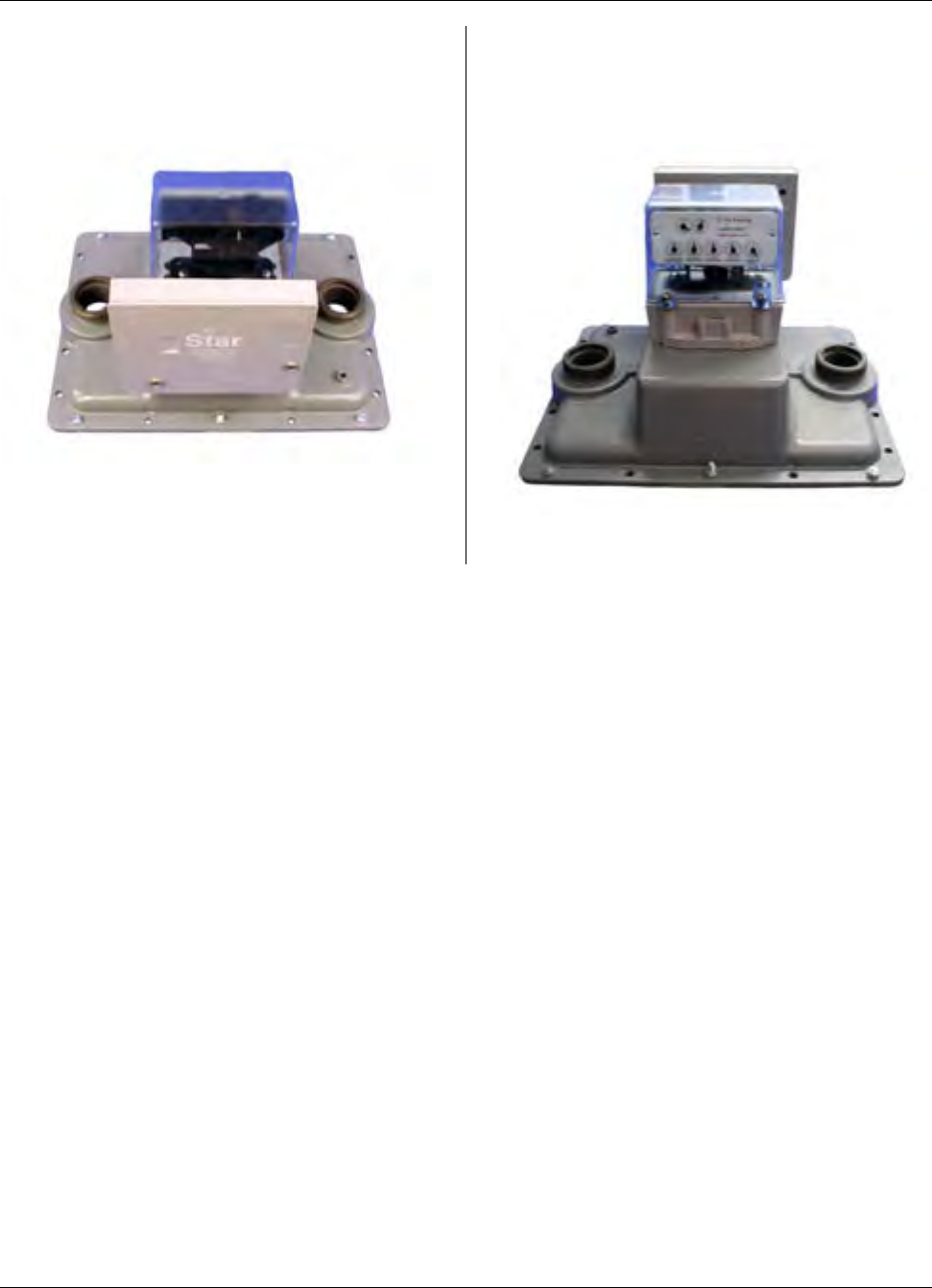
MTU Instruction
for Sprague/Actaris 675A, 800A and 1000A Gas Meters
Step 13 - Mount the MTU to the adaptor
using the two ¼-20 x 1-½” Phillips pan
head machine screws and the ¼-20
nylock nuts.
Step 14 – Installation is now complete.
Program the MTU using the STAR
Programmer Software and your Field
Programmer.
Page 123

MTU Instruction
for Sprague/Actaris 675A, 800A and 1000A Gas Meters
Intentionally Left Blank
Page 124
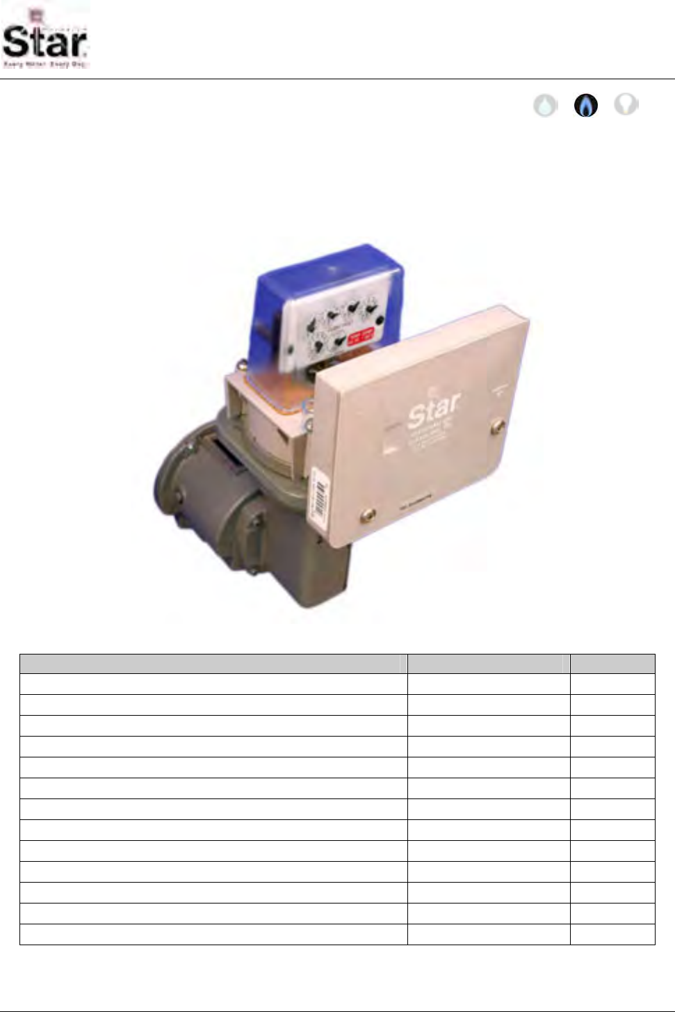
MTU Instruction
for Dresser Gas Meters with Vertical Mechanical Index
Purpose & Scope
This instruction provides a procedure for use in installing a Hexagram STAR MTU and
Large Meter Pulser on Dresser Roots-Type Gas Meters with Vertical Mechanical
Index. Please also refer to Publication 471-2000, General Installation and Wiring
Guidelines for general information covering the wiring and mounting of STAR MTUs.
Parts Required
Item Part Number Quantity
5/16-18 x 3” slotted round head bolt, stainless 069-561896DS 4
#12-24 x 2-¼” slotted fillister head screw, stainless 069-122472HS 2
American index cover gasket 066-0033 1
Security cups 066-0336 2
Security caps 066-0337 2
2-pin drive disk 056-11585C 1
Tall, 2-slot coupler with magnet 056-11585B 1
Shaft, standard 056-5155D 1
Adapter, 5155 style MTU enclosure to pulser body 056-11585D 1
¼-20 x 1-½” Phillips pan head machine screw, stainless 069-142048AS 2
¼-20 nylock nut, stainless 069-3222 2
#8-18 x ½” Phillips pan head thread forming screw, stainless 069-080016A4S 2
MTU/Pulser Assembly (or separate MTU and pulser) per project 1
471-2029 - 7/18/2007
Page 125
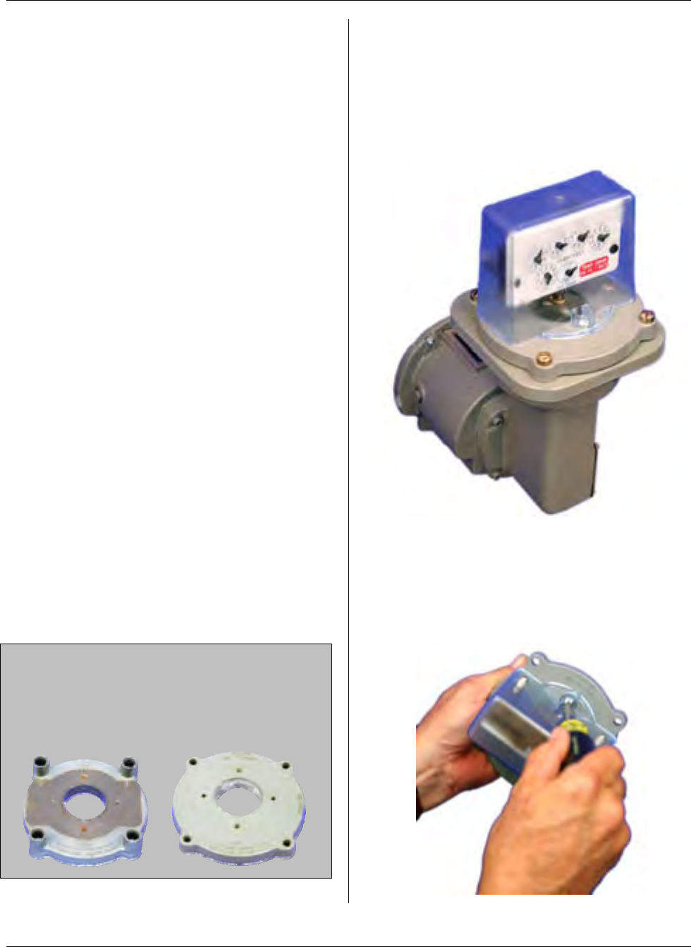
MTU Instruction
for Dresser Gas Meters with Vertical Mechanical Index
Tools Required
• Screwdriver, #2 Phillips
• Screwdriver, 3/8” slotted (flat-
blade)
• 7/16” box wrench
• 5/16-18 blind-hole (bottoming) tap
and mating size T-handle
• 12-24 blind-hole (bottoming) tap
and mating size T-handle
• Canned compressed air
Also see Publication 471-2000, General
Installation and Wiring Guidelines for a
complete list of recommended tools and
supplies for MTU Installation.
Installation Procedure
There are two parts to this procedure.
First, the pulser must be mounted to the
meter. Once this is complete, you can
mount the MTU remotely or directly on
the pulser using the adapter provided. If
you are mounting the MTU on the pulser,
it can be mounted at either the front or
back of the register.
Step 1 – If necessary, remove tamper
seals from any of the 4 screws that
secure the index base plate and the two
screws that secure the index box to the
base plate.
Note: If the index base plate has integral
security towers like the one on the left
below, it must be replaced with the flat
style index base plate like the one shown
on the right.
Step 2- Loosen and remove the four
screws securing the index base plate
assembly to the instrument drive. You
may discard these screws as they will not
be re-used. Remove the index box and
base plate assembly from the top of the
meter.
Step 3 – Disassemble the index box from
the base plate by removing the two
screws that secure the index box to the
base plate. You may discard these
screws as they will not be re-used.
Page 126
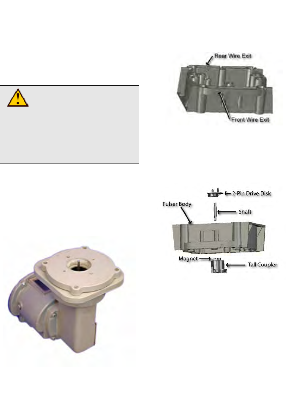
MTU Instruction
for Dresser Gas Meters with Vertical Mechanical Index
Step 4 – If the index box and/or base
plate mounting screws were difficult to
remove, the threads in the meter head
may need to be cleaned out before
installing the new hardware that will retain
the index base plate, the pulser and the
index box. Use the blind-hole taps to
carefully clean the threads of the index
box and base plate mounting holes.
CAUTION!
The index base plate
mounting holes use a 5/16-18
thread. The index box
mounting holes use a #12-24
thread. Be sure to use the
proper tap for each hole.
Using the wrong tap will result
in damage to the meter head.
After using the tap, blow out the holes
with compressed (canned) air.
Step 5 – Place the index base plate onto
the instrument drive of the meter. Align
the index base plate with the index plate
mounting holes on the instrument drive so
that the large opening in the base plate is
centered over the drive mechanism.
Step 6 – Break out the tab for either the
front or rear wire exit on the bottom edge
of the pulser body, depending on how you
plan to mount the MTU. (See the
illustration below.)
Step 7 – Assemble the couplers and
shaft to the pulser body as shown in the
illustration below. Ensure that the
magnet is mounted on the Tall Coupler,
and that the retaining shaft is securely
snapped into both the Tall Coupler and
the 2-Pin Drive Disk.
Page 127
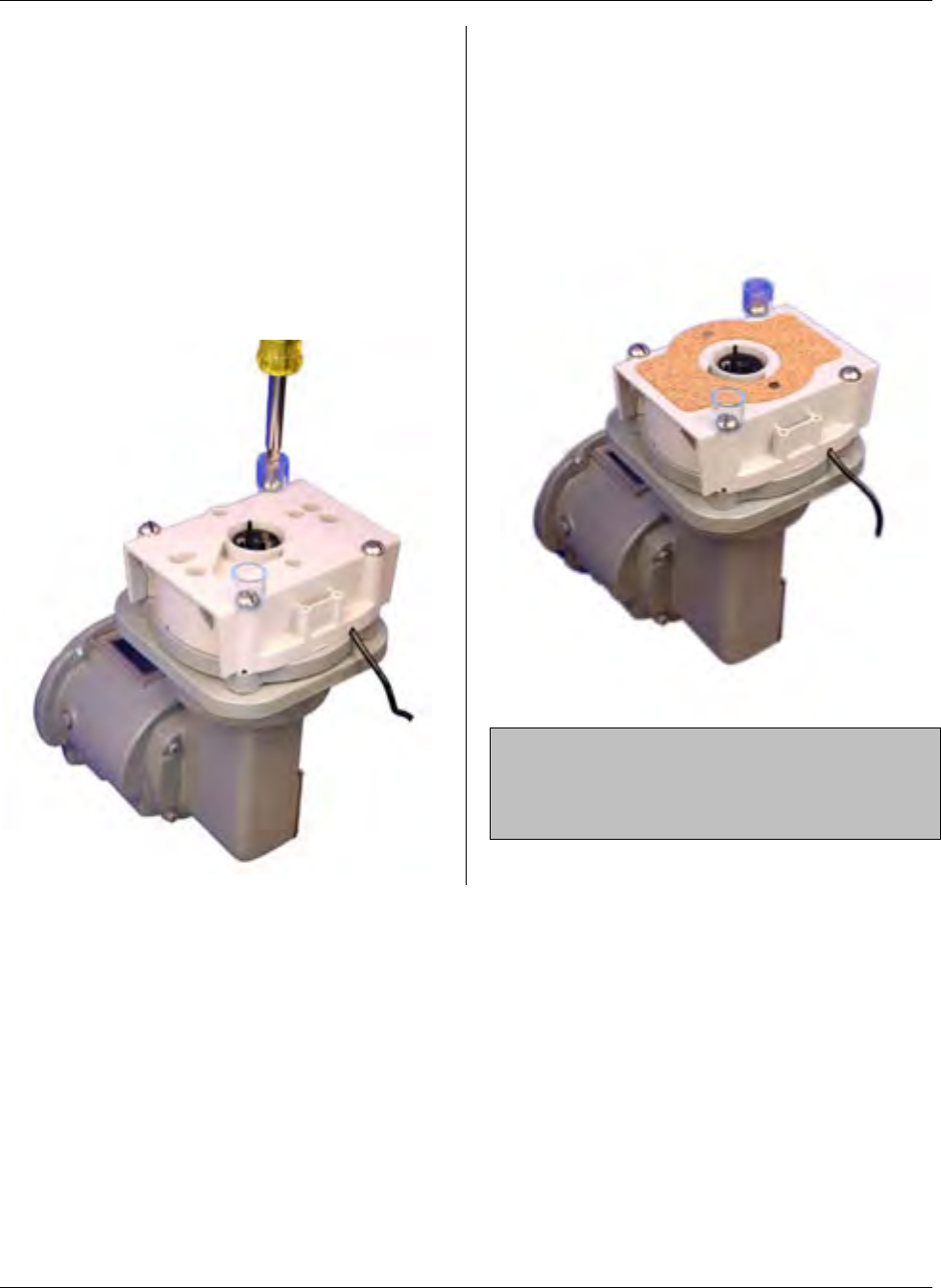
MTU Instruction
for Dresser Gas Meters with Vertical Mechanical Index
Step 8 – Place the pulser on the index
base plate, aligning the bottom coupler on
the pulser with the wiggler on the meter.
Align the corner mounting holes on the
pulser with the mounting holes on the
index base plate.
Step 9 – Fasten the pulser to the
instrument drive using the four 5/16-18 x
3” slotted, stainless steel round head
bolts provided. Install security cups, if
desired, as shown below.
Step 10 – If the index box assembly has
a silicone gasket applied around its
bottom edge and that gasket is in good
shape, you can discard the index cover
gasket supplied with the pulser and skip
to Step 11. Otherwise, place the index
cover gasket on the pulser, aligning the
gasket as shown below.
NOTE: When using the cork gasket
supplied with the pulser, be sure that the
bottom edge of the index box is clean and
free of any silicone and/or dirt particles.
Page 128
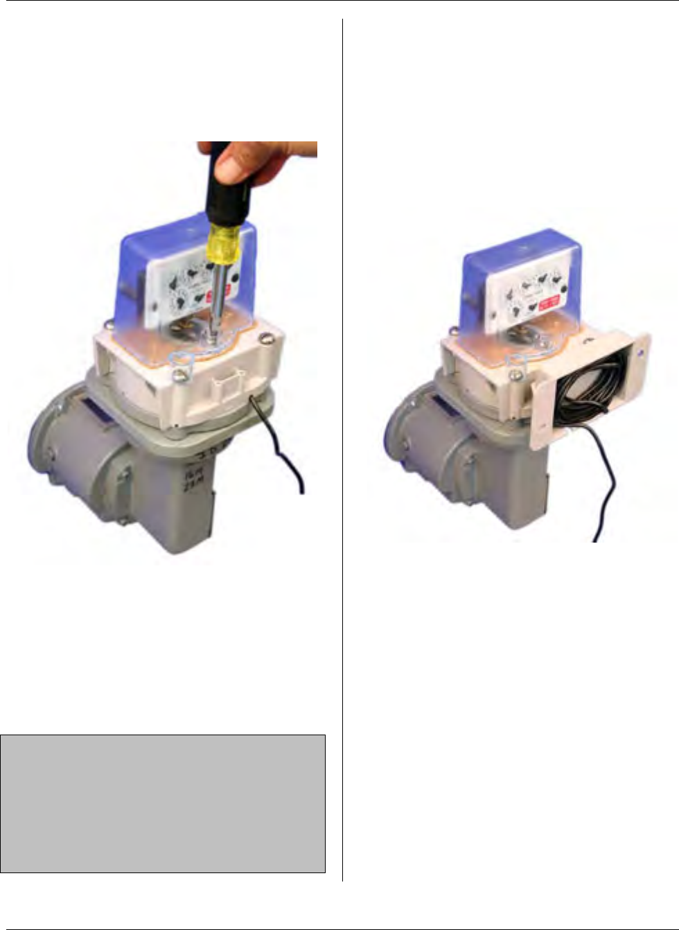
MTU Instruction
for Dresser Gas Meters with Vertical Mechanical Index
Step 11 – Place the index box assembly
on the pulser, aligning the the drive foot
with the two-pin drive disk. Fasten the
index box to the meter with the two #12-
24 x 2-¼” slotted, stainless steel fillister
head screws provided.
Installation of the pulser is now complete.
If you will be remotely mounting the MTU,
refer to Publication 471-2000, General
Installation and Wiring Guidelines for
general information covering the wiring
and mounting of STAR MTUs. Continue
to Step 12 if you will be mounting the
MTU to the pulser body.
NOTE: The pulser and MTU can be
supplied pre-wired or as separate
assemblies. If provided as separate
components, connect the three wires in
the pulser cable (red, black, and white) to
the corresponding wires in the MTU
cable.
Step 12 – Continue here to mount the
MTU to the pulser using the adaptor
provided. Begin by positioning the
adaptor on the back (or front) of the
pulser body and attach it using the two
#8-18 x ½” Phillips pan head thread
forming screws provided.
Step 13 – Bundle the excess wire into the
compartment on the adaptor.
Page 129

MTU Instruction
for Dresser Gas Meters with Vertical Mechanical Index
Step 14 - Mount the MTU to the adaptor
using the two ¼-20 x 1-½” Phillips pan
head machine screws and the ¼-20
nylock nuts.
Step 15 – Installation is now complete.
Program the MTU using the STAR
Programmer Software and your Field
Programmer.
Page 130
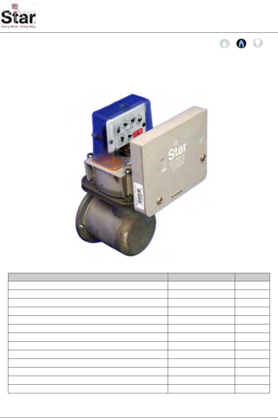
MTU Instruction
for Romet Gas Meters with Vertical Mechanical Index
Purpose & Scope
This instruction provides a procedure for use in installing a Hexagram STAR MTU and
Large Meter Pulser on Romet Roots-Type Gas Meters with Vertical Mechanical
Index. Please also refer to Publication 471-2000, General Installation and Wiring
Guidelines for general information covering the wiring and mounting of STAR MTUs.
Parts Required
Item Part Number Quantity
5/16-18 x 3” slotted round head bolt, stainless 069-561896DS 4
#12-24 x 2-¼” slotted fillister head screw, stainless 069-122472HS 2
American index cover gasket 066-0033 1
Security cups 066-0336 2
Security caps 066-0337 2
2-pin drive disk 056-11585C 1
Tall, 2-slot coupler with magnet 056-11585B 1
Shaft, standard 056-5155D 1
Adapter, 5155 style MTU enclosure to pulser body 056-11585D 1
¼-20 x 1-½” Phillips pan head machine screw, stainless 069-142048AS 2
¼-20 nylock nut, stainless 069-3222 2
#8-18 x ½” Phillips pan head thread forming screw, stainless 069-080016A4S 2
MTU/Pulser Assembly (or separate MTU and pulser) per project 1
471-2030 - 7/18/2007
Page 131
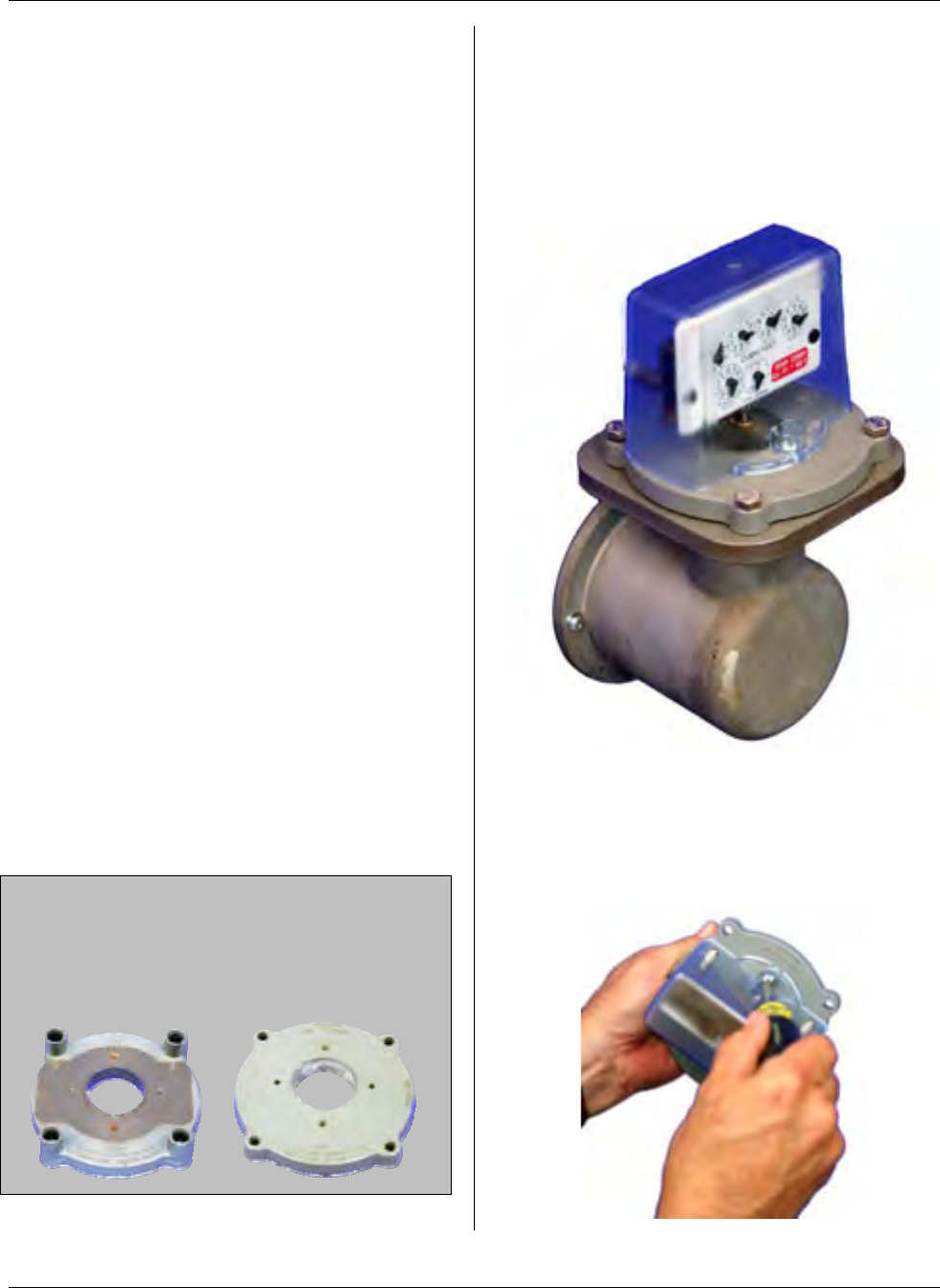
MTU Instruction
for Romet Gas Meters with Vertical Mechanical Index
Tools Required
• Screwdriver, #2 Phillips
• Screwdriver, 3/8” slotted (flat-
blade)
• 7/16” box wrench
• 5/16-18 blind-hole (bottoming) tap
and mating size T-handle
• 12-24 blind-hole (bottoming) tap
and mating size T-handle
• Canned compressed air
Also see Publication 471-2000, General
Installation and Wiring Guidelines for a
complete list of recommended tools and
supplies for MTU Installation.
Installation Procedure
There are two parts to this procedure.
First, the pulser must be mounted to the
meter. Once this is complete, you can
mount the MTU remotely or directly on
the pulser using the adapter provided. If
you are mounting the MTU on the pulser,
it can be mounted at either the front or
back of the meter.
Step 1 – If necessary, remove tamper
seals from any of the 4 screws that
secure the index base plate and the two
screws that secure the index box to the
base plate.
Note: If the index base plate has integral
security towers like the one on the left
below, it must be replaced with the flat
style index base plate like the one shown
on the right.
Step 2- Loosen and remove the four
screws securing the index base plate
assembly to the instrument drive. You
may discard these screws as they will not
be re-used. Remove the index box and
base plate assembly from the top of the
meter.
Step 3 – Disassemble the index box from
the base plate by removing the two
screws that secure the index box to the
base plate. You may discard these
screws as they will not be re-used.
Page 132
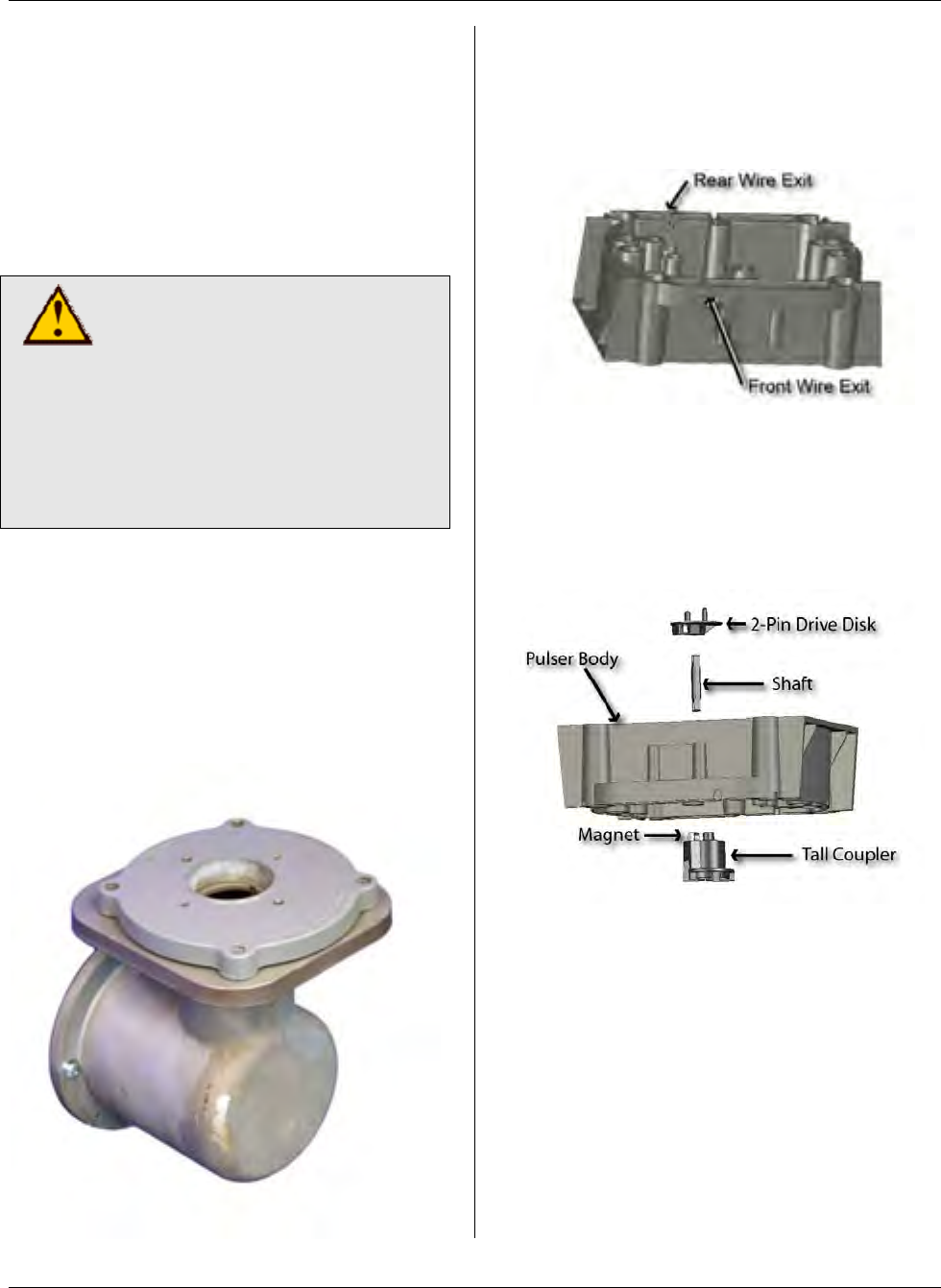
MTU Instruction
for Romet Gas Meters with Vertical Mechanical Index
Step 4 – If the index box and/or base
plate mounting screws were difficult to
remove, the threads in the meter head
may need to be cleaned out before
installing the new hardware that will retain
the index base plate, the pulser and the
index box. Use the blind-hole taps to
carefully clean the threads of the index
box and base plate mounting holes.
CAUTION!
The index base plate
mounting holes use a 5/16-18
thread. The index box
mounting holes use a #12-24
thread. Be sure to use the
proper tap for each hole.
Using the wrong tap will result
in damage to the meter head.
After using the tap, blow out the holes
with compressed (canned) air.
Step 5 – Place the index base plate onto
the instrument drive of the meter. Align
the index base plate with the index plate
mounting holes on the meter head so that
the large opening in the base plate is
centered over the drive mechanism.
Step 6 – Break out the tab for either the
front or rear wire exit on the bottom edge
of the pulser body, depending on how you
plan to mount the MTU. (See the
illustration below.)
Step 7 – Assemble the couplers and
shaft to the pulser body as shown in the
illustration below. Ensure that the
magnet is mounted on the Tall Coupler,
and that the retaining shaft is securely
snapped into both the Tall Coupler and
the 2-Pin Drive Disk.
Page 133
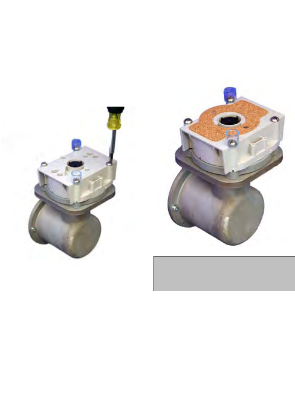
MTU Instruction
for Romet Gas Meters with Vertical Mechanical Index
Step 8 – Place the pulser on the index
base plate, aligning the bottom coupler on
the pulser with the wiggler on the meter.
Align the corner mounting holes on the
pulser with the mounting holes on the
index base plate.
Step 9 – Fasten the pulser to the
instrument drive using the four 5/16-18 x
3” slotted, stainless steel round head
bolts provided. Install security cups, if
desired, as shown below.
Step 10 – If the index box assembly has
a silicone gasket applied around its
bottom edge and that gasket is in good
shape, you can discard the index cover
gasket supplied with the pulser and skip
to Step 11. Otherwise, place the index
cover gasket on the pulser, aligning the
gasket as shown below.
NOTE: When using the cork gasket
supplied with the pulser, be sure that the
bottom edge of the index box is clean and
free of any silicone and/or dirt particles.
Page 134
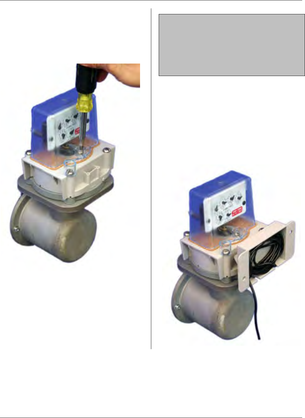
MTU Instruction
for Romet Gas Meters with Vertical Mechanical Index
Step 11 – Place the index box assembly
on the pulser, aligning the the drive foot
with the two-pin drive disk. Fasten the
index box to the meter with the two #12-
24 x 2-¼” slotted, stainless steel fillister
head screws provided.
Installation of the pulser is now complete.
If you will be remotely mounting the MTU,
refer to Publication 471-2000, General
Installation and Wiring Guidelines for
general information covering the wiring
and mounting of STAR MTUs. Continue
to Step 12 if you will be mounting the
MTU to the pulser body.
NOTE: The pulser and MTU can be
supplied pre-wired or as separate
assemblies. If provided as separate
components, connect the three wires in
the pulser cable (red, black, and white) to
the corresponding wires in the MTU
cable.
Step 12 – Continue here to mount the
MTU to the pulser using the adaptor
provided. Begin by positioning the
adaptor on the back (or front) of the
pulser body and attach it using the two
#8-18 x ½” Phillips pan head thread
forming screws provided.
Step 13 – Bundle the excess wire into the
compartment on the adaptor.
Page 135
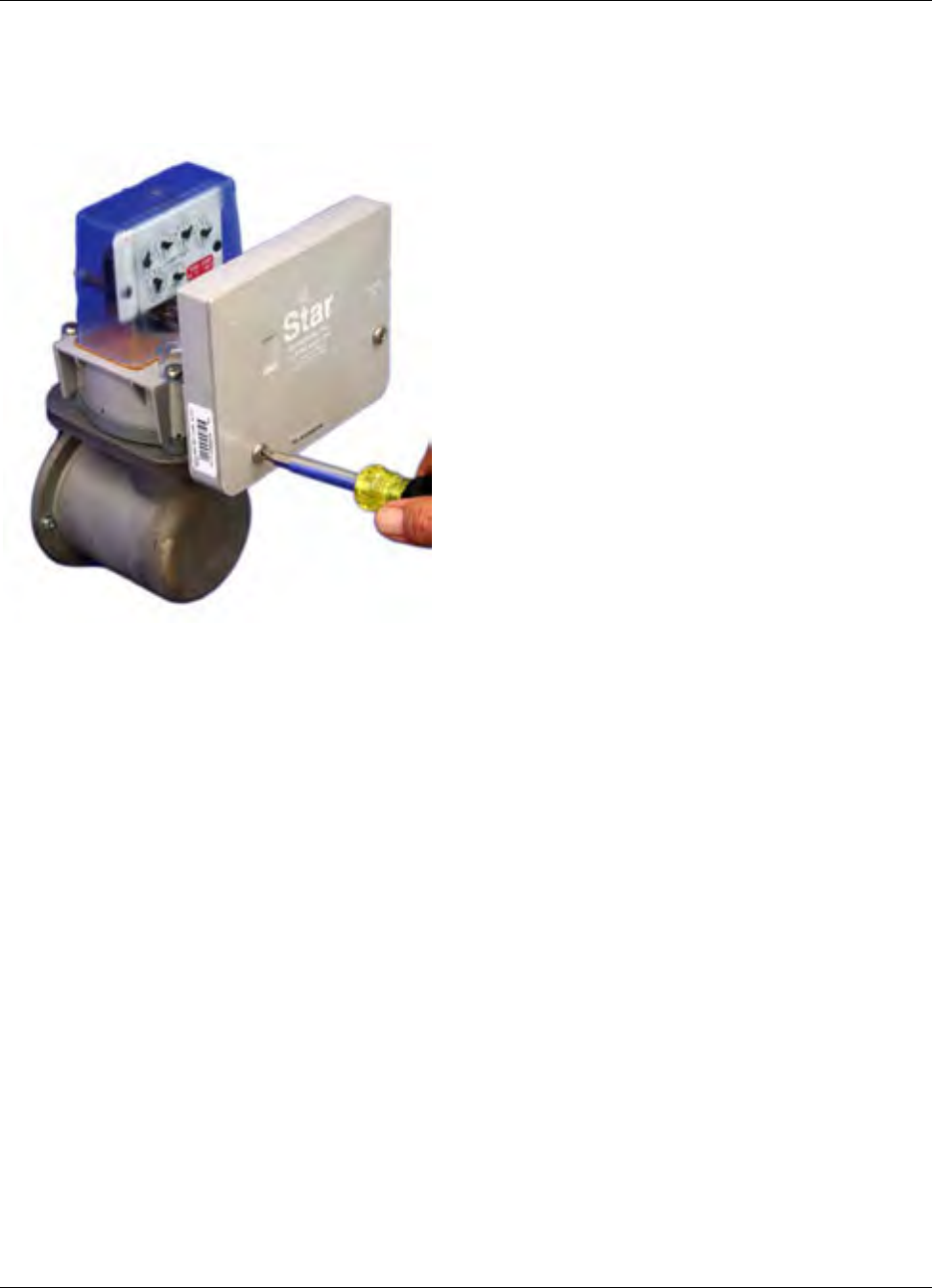
MTU Instruction
for Romet Gas Meters with Vertical Mechanical Index
Step 14 - Mount the MTU to the adaptor
using the two ¼-20 x 1-½” Phillips pan
head machine screws and the ¼-20
nylock nuts.
Step 15 – Installation is now complete.
Program the MTU using the STAR
Programmer Software and your Field
Programmer.
Page 136
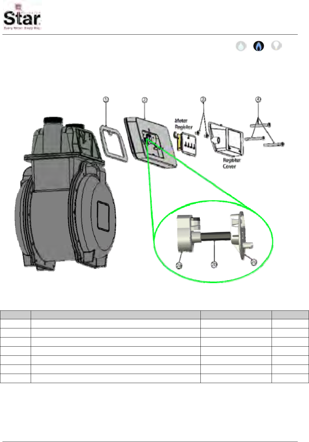
MTU Instruction
for Actaris/Sprague/Schlumberger Gas Meters
Purpose & Scope
This instruction provides a procedure for installing a STAR direct-mount MTU on the
following Actaris/Sprague/Schlumberger residential gas meters: 175, 250 and 400 (Slant-
face).
Parts Required
Ref. # Item Part Number Quantity
1 Gasket 066-11583 1
2 MTU, Sprague Direct Mount per project 1
2a Magnet Coupler 056-11703B 1
2b Coupler Shaft 056-5155D 1
2c Register Coupler 056-11583D 1
3 #10 x 3/8” combo head thread form screw, Type A, zinc 069-100012C3A 2
4 10-24 x 2” slotted fillister head machine screw, zinc 069-102464HA 3
471-2031 - 7/18/2007
Page 137
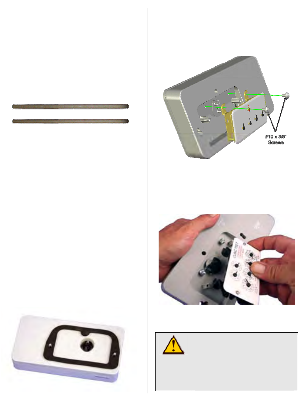
MTU Instruction
for Actaris/Sprague/Schlumberger Gas Meters
Tools Required
To mount the MTU to these meters, you
will need the following tools and
equipment:
• Safety glasses
• #2 Phillips screwdriver
• ¼” Slotted screwdriver
• 2 alignment studs – Hexagram
part number xxx-yyyy
Installation Procedure
Before installing the MTU, all anti-tamper,
safety, and security hardware must be
removed from the clear register cover.
Step 1 - Remove the existing clear
register cover by removing the three
screws that hold it. Set the cover aside
and discard the screws.
Step 2 - Remove the register by
removing the two screws that hold it. Set
the register aside and discard the screws.
Step 3– Remove the paper backing from
the gasket provided to expose the
pressure sensitive adhesive. Place the
gasket on the back of the MTU with the
adhesive surface facing the MTU so that
it aligns over the three mounting screws
and the raised gasket surface of the
MTU.
Step 4 – Next, turn the MTU over and
mount the register onto the MTU (see
illustration below) fastening the register to
the MTU with the #10 x 3/8” screws
provided.
Start the two screws into the mounting
holes, and then slide the register beneath
the screws, making sure that the wiggler
on the register is aligned with the MTU
coupler.
Tighten both screws to a torque not to
exceed 3-5 inch-pounds.
CAUTION!
Do not over tighten screws.
Excessive torque may
damage the MTU enclosure.
Use of power tools is not
recommended.
Page 138
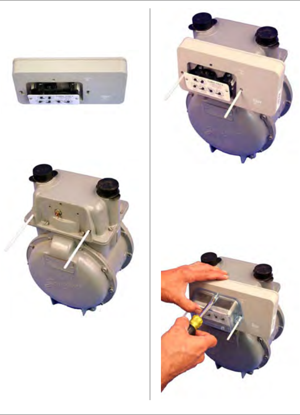
MTU Instruction
for Actaris/Sprague/Schlumberger Gas Meters
Step 5 – Check that the register is
properly engaged by rotating the coupler
on the back of the MTU and observing
the register dials.
Step 6 – Next, thread alignment studs
into the threaded mounting holes on the
left and right side of the index box, as
shown below.
Step 7 – Next, slide the MTU over the
alignment studs, positioning the coupler
on the MTU to ensure that it engages
correctly with the wiggler on the gas
meter.
Step 8 – Now, slide the clear register
cover over the alignment studs while you
hold the MTU in position with your free
hand.
Step 9 - Next, insert one of the #10-24 x
2” screws through the top-center hole on
the clear register cover. Tighten this
screw just sufficiently to hold the MTU
and register cover to the meter.
Page 139

MTU Instruction
for Actaris/Sprague/Schlumberger Gas Meters
Step 10 – Next, remove one of the
alignment studs and replace it with
another one of the #10-24 x 2” screws
provided. Continue in a similar manner,
replacing the other alignment stud with a
#10-24 x 2” screw. Tighten all three
screws to a torque not to exceed 12 -15
inch-pounds. The gasket should be
compressed slightly. Be careful not to
over tighten the screws. Excessive torque
may damage the MTU enclosure.
Because of this, power tools are not
recommended for this procedure.
Step 11 - Replace any anti-tamper,
safety, or security hardware onto the
plastic cover as required.
Step 12 – Once Installation is complete,
program the MTU using your field
programmer and the STAR Programmer
Software.
Page 140
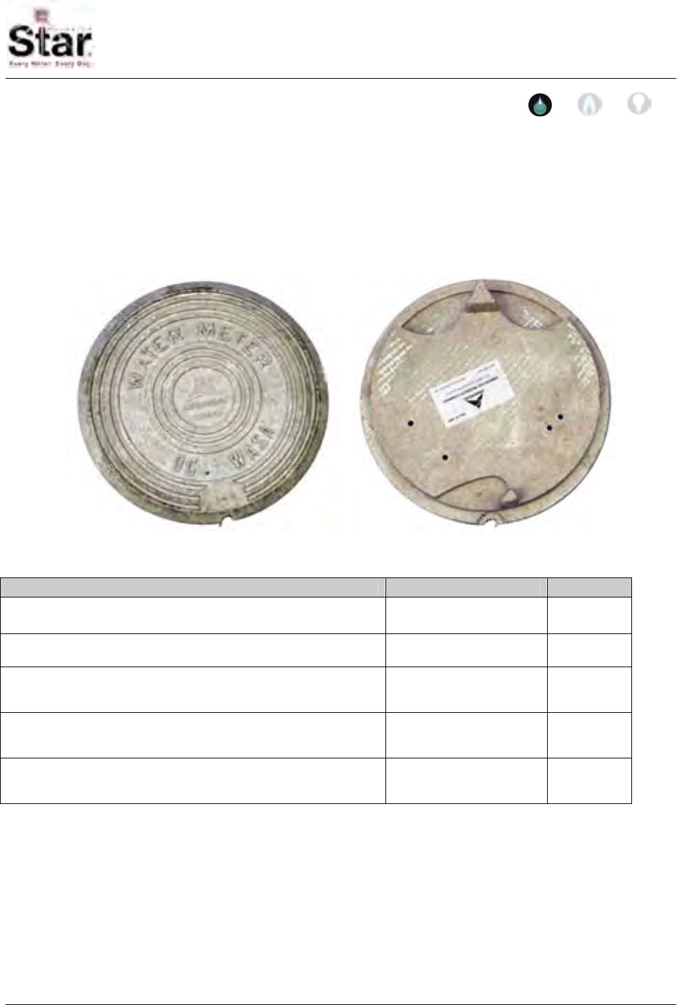
MTU Instruction
for Armorcast Composite Pit Lids
Purpose & Scope
This instruction provides a procedure for mounting a STAR MTU to an Armorcast
Composite Pit Lid. This procedure covers the mounting of an Original Flatpak STAR MTU
or the New Flatpak STAR MTU to these pit lids. This procedure does not detail the wiring
of the MTU to the meter inside of the pit. Please refer to Publication 471-2000, General
Installation and Wiring Guidelines in addition to any meter specific MTU installation and
programming instructions.
Parts Required
Item Part Number Quantity
MTU As required for installed
meter 1
Hillman #370342 (10-12x1”) Anchors 2 per
installation
#8 x 2” Galvanized Sheet Metal Screws 2 per Original
Style MTU
installation
Long Spacers (for pit lid mounting of New Style Flatpak
MTUs) 056-8150L 2 per New
Style MTU
installation
#8 x 2 1/2” Galvanized Sheet Metal Screws 2 per New
Style MTU
installation
Tools Required
To mount the MTU to these pit lids, you
will need the following tools and
equipment:
• Safety goggles
• #2 Phillips driver bit
• Hammer
• #2 Phillips Screwdriver
• Cordless Drill 3/8”, variable speed,
with adjustable torque settings.
471-2032 - 9/22/2006
Page 141
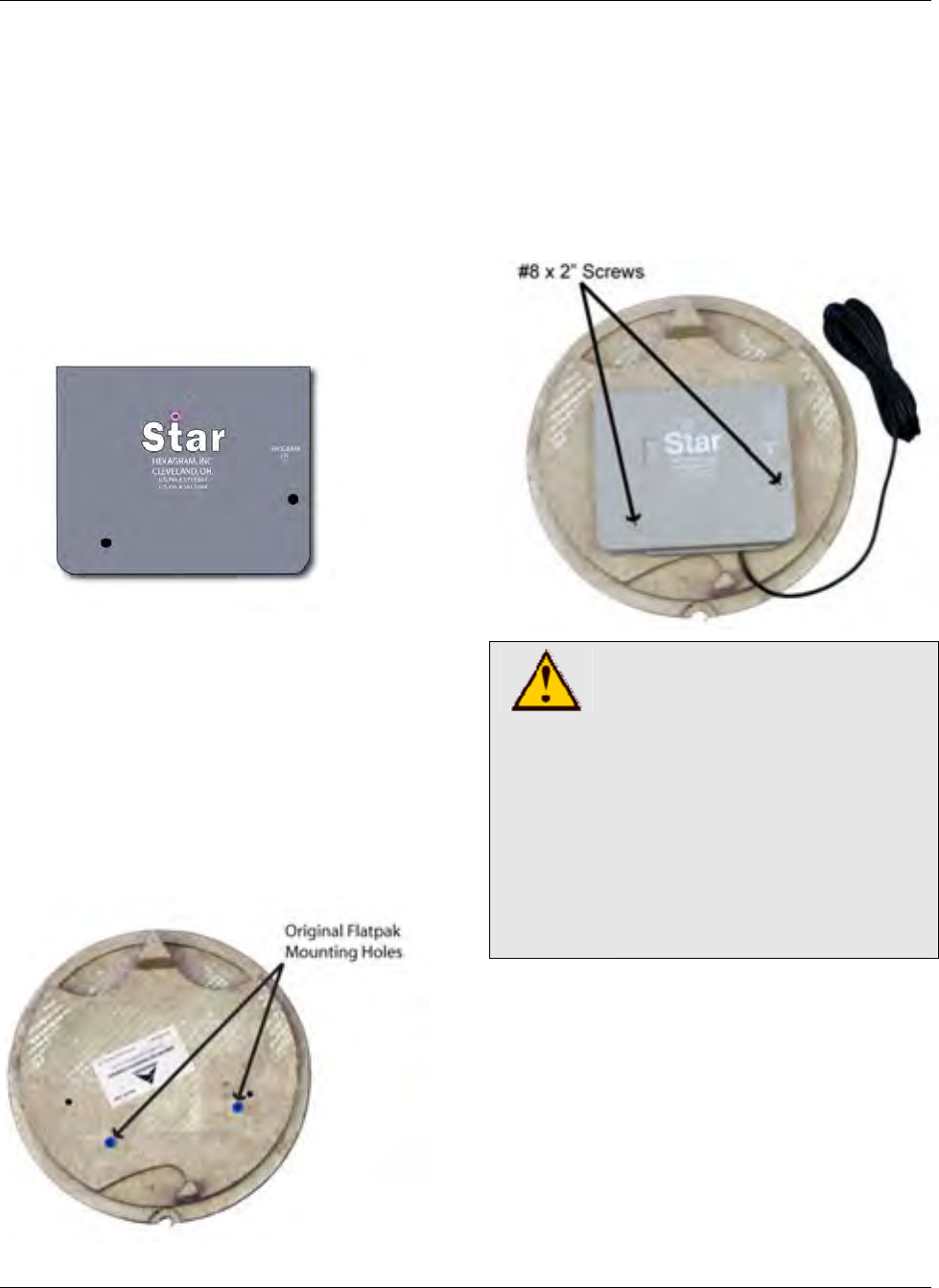
MTU Instruction
for Armorcast Composite Pit Lids
Note on setting the torque range: On a
drill-driver that has about 20 settings
(positions), set the adjustment to #6. Use
the lower speed range of the drill-driver.
This should amount to approximately 8 in-
lbs of torque. Reference the operating
instructions for your particular drill to
more accurately determine what setting to
use to achieve a torque range of
approximately 8 in-lbs.
Step 3 – Use a hammer to gently tap
anchors into the holes indicated in the
previous photo.
Step 4 – Position the MTU face-up on the
bottom surface of the pit lid. Place 2 #8 x
2” galvanized sheet metal screws through
the mounting holes as shown below, and
guide the screws into the anchors.
Installation Procedure
Mounting an Original Flatpak STAR
MTU to an Armorcast pit lid.
Step 1 – Place the pit lid top down on a
solid surface.
Step 2 – Note the pre drilled mounting
holes on the bottom of the pit lid. The
holes used for mounting an Original
Flatpak STAR MTU are highlighted in the
photo below.
CAUTION!
Do not over tighten screws.
Excessive torque may
damage the MTU enclosure.
Do not tighten screws beyond
the point that the MTU
touches the mounting surface.
Power tools are not
recommended for use when
mounting an Original Flatpak
STAR MTU to Armorcast lids.
Step 5 – Hand tighten the screws to
approximately 8 in-lbs. MTU should be
snug to the surface o
Step 6 – W r,
making sur t
it does not
is closed.
f the pit lid.
ire the MTU to the mete
e that the wire is routed so tha
become pinched when the lid
Page 142
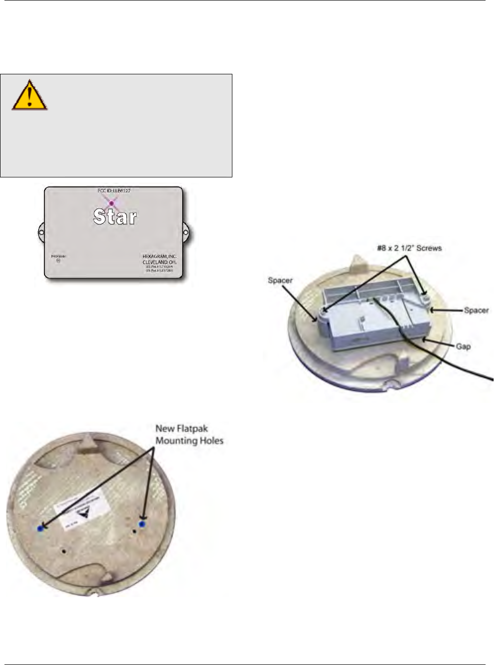
MTU Instruction
for Armorcast Composite Pit Lids
Step 7 - Installation is now complete. You
can now pr
using the S
and your MTU Programmer.
Step 3 – Use a hammer to gently tap
anchors into the holes indicated in the
previous photo.
Step 4 – Position the MTU face-down on
the bottom surface of the pit lid as shown
below. Insure that cable exit from the
MTU faces the rim of the lid.
Step 5 - Place plastic spacers under the
mounting lugs on the MTU as shown
below. Position the spacers so that the
notched ends mate up with the mounting
tabs on the MTU. Note that the spacers
lid
oceed to program the MTU
TAR Programmer Software
CAUTION!
Be sure to follow all General
Guidelines outlined in
Publication 471-2000 along
with the specific wiring
instructions for the meter
being used.
Mounting o
an Armorc
Step 1 – Place the pit lid top down on a
solid surfac
Step 2 – Note the pre drilled mounting
holes on the bottom of the pit lid. The
holes used for mounting an New Flatpak
STAR MTU are highlighted in the photo
below.
a New Flatpak STAR MTU t
ast pit lid.
e.
should provide a gap of approximately
3/8” between the bottom surface of the
and the top surface of the MTU.
Step 6 - Place 2 #8 x 2 ½” galvanized
sheet metal screws through the mounting
holes and the spacers, and guide the
screws into the anchors.
Step 7 – Torque screws to approximately
8 in-lbs. MTU should be snug to the
surface of the pit lid.
Step 8 – Wire the MTU to the meter,
making sure that the wire is routed so that
it does not become pinched when the lid
is closed.
Step 9 - Installation is now complete. You
and your MTU Programmer.
can now proceed to program the MTU
using the STAR Programmer Software
Page 143

MTU Instruction
for Armorcast Composite Pit Lids
Inte
ntionally Left Blank
Page 144
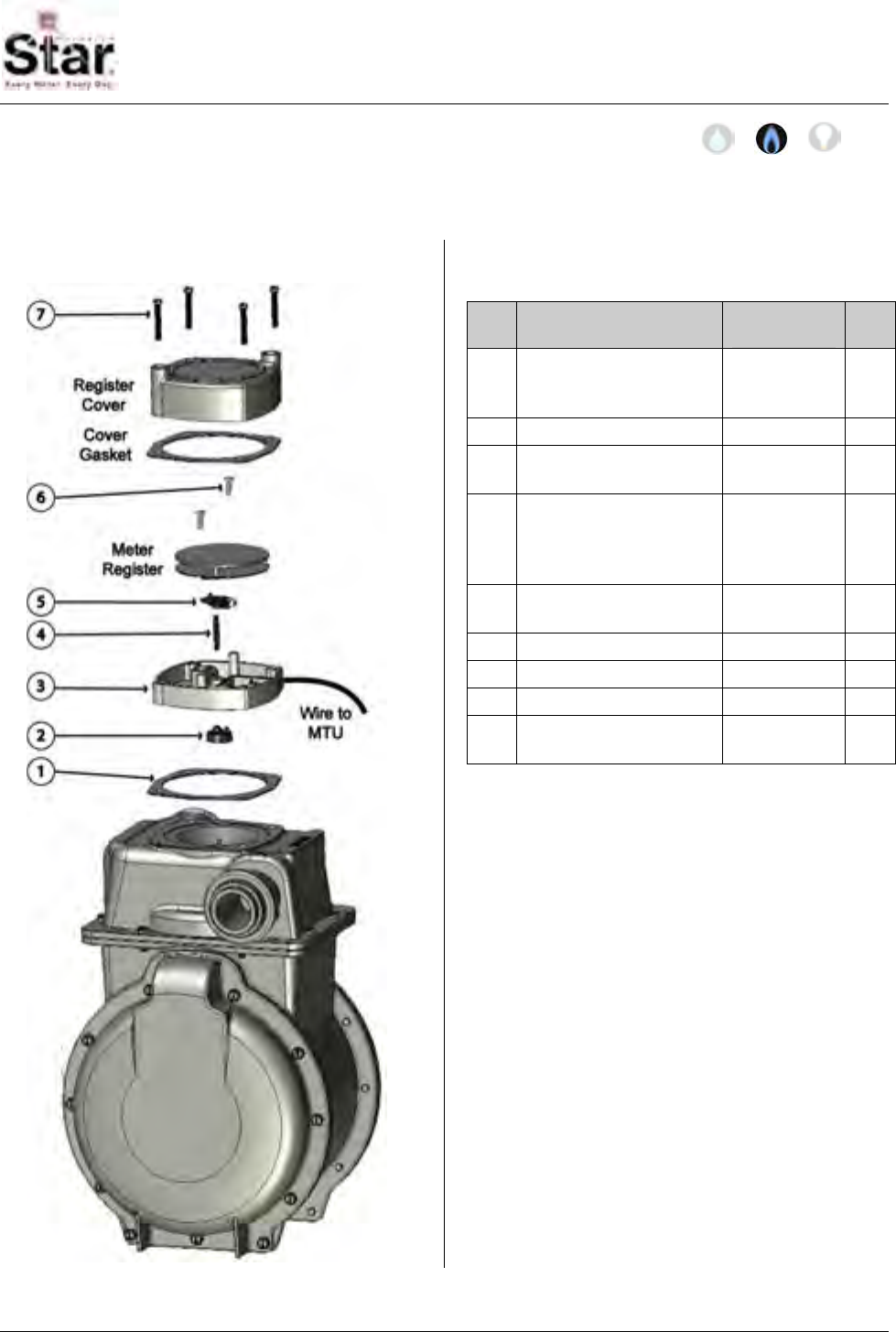
MTU Instruction
for Sprague/Actaris 'Curb-type' Gas Meters
Purpose & Scope
This instruction provides a procedure for use in installing a Hexagram STAR MTU and
Pulser on a Sprague/Actaris ‘Curb-type’ Gas Meter with top mounted index.
Parts Required
Ref Item Part
Number Qty
1 #10-32 x 2” slotted
fillister head machine
screw, brass
069-
103264HC 4
2 Register (Index) Cover 056-0561 1
3 Cover Gasket,
notched 066-0037 1
4 #6-19 x ½” Phillips
pan head, hi-low
thread forming screw,
stainless
069-
060016A4S 2
5 Single-pin Index Drive,
with Magnet 056-11583D 1
6 Shaft, standard 056-5155D 1
7 MTU/Pulser Assembly 506-11703 1
8 Coupler 056-11703B 1
9 Neoprene rubber
gasket 066-0035 1
Tools Required
• Wire Brush
• Screwdriver, #2 Phillips
• Screwdriver, 3/8” slotted (flat-
blade)
• Two (2) Alignment Studs
Also see Publication 471-2000, General
Installation and Wiring Guidelines for a
complete list of recommended tools and
supplies for MTU Installation.
Installation Procedure
There are two parts to this procedure.
First, the pulser must be mounted to the
meter. Then, the MTU must be mounted
in a nearby location that will allow RF
transmissions to propagate.
471-2033 - 4/28/2008
Page 145
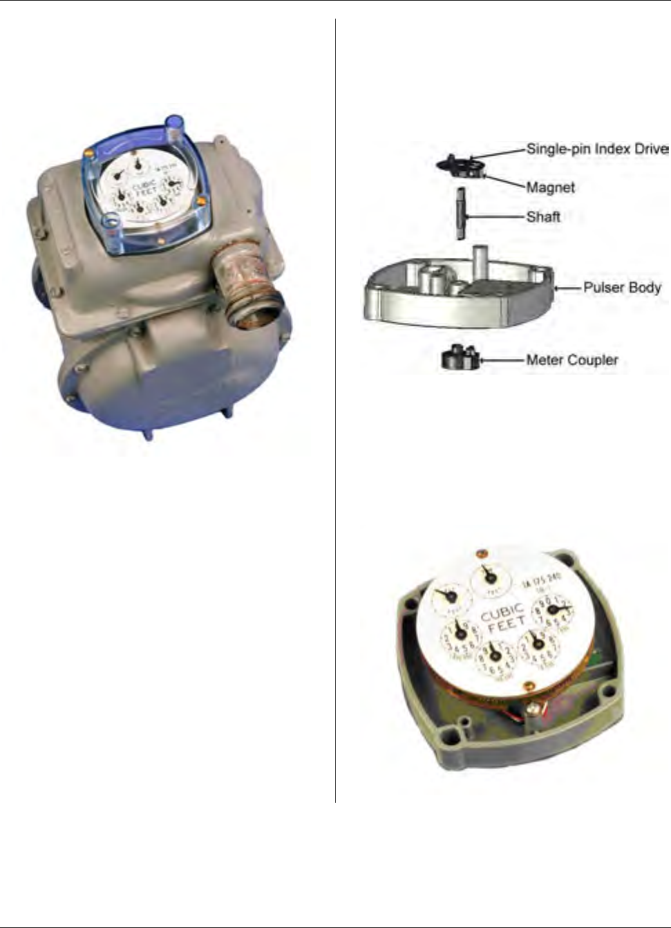
MTU Instruction
for Sprague/Actaris 'Curb-type' Gas Meters
Refer to Publication 471-2000, General
Installation and Wiring Guidelines for
general information covering the wiring
and mounting of STAR MTUs.
Step 1 – If necessary, remove tamper
seals from any of the four screws that
secure the index cover to the meter body.
Step 2- Loosen and remove the four
screws securing the index cover to the
meter. You may discard these screws as
they will not be re-used. Remove the
index cover and the index cover gasket
from the top of the meter and discard.
You will replace both the cover and the
gasket during reassembly.
Step 3 – Remove the two screws
securing the index to the top of the meter.
You may discard these screws as they
will not be re-used. Remove the index
register and set it aside.
Step 4 – Verify that the couplers and
shaft are attached to the pulser body as
shown below. Ensure that these
components are securely snapped
together and that the magnet is in place
on the Single-pin Index Drive.
Step 5 – Mount the index to the pulser
using the #6-19 Phillips screws provided.
You can start the screws in the posts on
the pulser body first. Then engage the
tabs on the index with the mounting
screws. Ensure that the pin on the index
drive engages the wiggler on the index.
Page 146

MTU Instruction
for Sprague/Actaris 'Curb-type' Gas Meters
Step 6 – Place the gasket provided onto
the meter, aligning it as shown to insure
that the openings for the index cover bolts
match up with the threaded holes on the
top of the meter. Use the two (2)
alignment studs to aid in alignment and
assembly of parts.
NOTE: PG&E Code 23-2097 for cover
gasket and Code 23-4931 for plastic
cover.
Step 7 – Position the pulser and index on
the meter, aligning the four holes with the
threaded holes on top of the meter.
Ensure that the coupler on the pulser
engages the drive dog on the meter. You
can orient the index in any direction.
Step 8 – Place the supplied index cover
and notched index cover gasket on the
pulser, again aligning the notches in the
gasket with the index mounting posts.
Then fasten the assembly to the meter
using the four #10-32 x 2” brass machine
screws provided. Alternately tighten
opposite screws to evenly compress the
gaskets.
NOTE: Use “red” security caps and
“putty” to seal screw wells.
Page 147
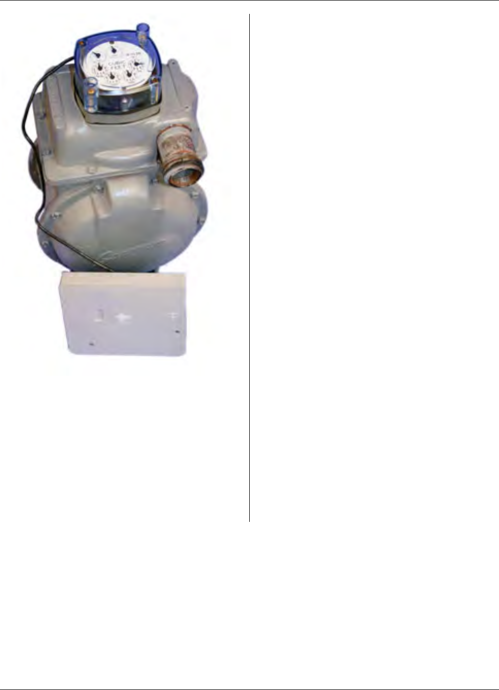
MTU Instruction
for Sprague/Actaris 'Curb-type' Gas Meters
Step 9 – Mount the MTU. Please refer to
Publication 471-2000, General
Installation and Wiring Guidelines for
general information covering the wiring
and mounting of STAR MTUs.
Step 10 – Installation is now complete.
Program the MTU using the STAR
Programmer Software and your Field
Programmer.
Page 148

MTU Instruction
for American Meter Company Gas Meters
Purpose & Scope
This instruction provides a procedure for installing a STAR direct-mount MTU on American
Meter Company 5B-225 meters.
Parts Required
Ref. # Item Part Number Quantity
1 Cork Gasket 066-12466B 1
2 Adaptor Plate 056-12466A 1
3 Rubber Gasket 066-12466A 1
4 MTU, Direct Mount per project 1
5 Coupler, MTU 056-5155E2 1
6 Extended Shaft 056-12466B 1
7 Coupler, MTU with Magnet (Magnet 036-0002) 056-5155E2 1
8 #8 x 3/8” Combo Head Sheet Metal Screw, Zinc 069-080012C4A 2
9 ¼-20 x 1 5/8” Slotted Fillister Head Machine Screw 069-142040GA 2
10 Register Cover 109-7712A 1
11 #10 x 1” Combo Head Sheet Metal Screw, Zinc 069-100032C3A 2
471-2034 - 7/18/2007
Page 149
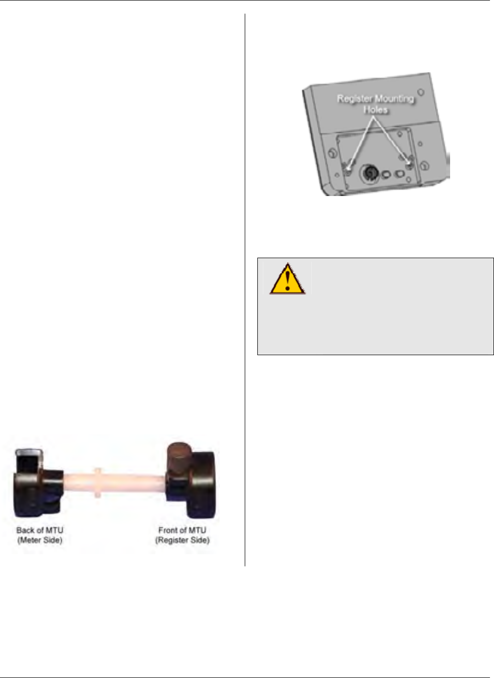
MTU Instruction
for American Meter Company Gas Meters
Tools Required
To mount the MTU to these meters, you
will need the following tools and
equipment:
• Safety glasses
• Phillips screwdriver
• Slotted screwdriver
Installation Procedure
Before installing the MTU, all anti-tamper,
safety, and security hardware must be
removed from the clear register cover.
Step 1 - Remove the existing clear
register cover by removing the four
screws that hold it. Discard both the
screws and the cover.
Step 2 - Remove the register by
removing the two screws that hold it. Set
the register aside. Discard the screws.
Step 3 – Assemble the couplers and
extended shaft to the MTU. Ensure that
the coupler with the magnet is on the
front (register side) of the MTU and that
the extended shaft protrudes from the
back of the MTU with the other coupler.
The notch of the front side coupler (with
magnet) should be at the 12 o’clock
position when the notch on the backside
coupler faces 3 o’clock (90°).
Step 4 - Mount the register onto the MTU,
fastening the register to the mounting
holes shown here with the #8 x 3/8”
screws provided.
Start one of the two screws into the
mounting hole, and then slide the register
beneath the screw aligning the wiggler on
the register with the MTU coupler.
CAUTION!
Do not over tighten screws.
Excessive torque may
damage the MTU enclosure.
Use of Power tools is not
recommended.
Then insert the second screw and tighten
both screws to a torque not to exceed 3-5
inch-pounds.
Note: On some odometer-style registers
like the one shown below, slight
protrusions on the back of the register
assembly can interfere with proper
alignment of the register. Should this
occur, use a diagonal cutting plier to trim
the two wire guides on the MTU to the
right of the coupler. Trim these guides as
close to flush with the MTU enclosure as
possible. (See MTU photo below.)
Page 150
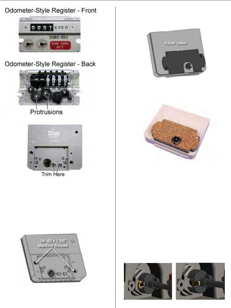
MTU Instruction
for American Meter Company Gas Meters
Step 5 – Check that the register is
properly engaged by rotating the coupler
on the back of the MTU and observing
the register dials.
Step 6 – Next, Insert the two ¼-20 x 1
5/8” machine screws through the holes on
the MTU as shown here.
Step 7– Turn the MTU over and place the
rubber gasket on the back of the MTU so
that it aligns over the two screws.
Step 8 – Next, place the adaptor plate on
the back of the MTU so that it aligns over
the two screws.
Step 9 – The cork gasket is normally pre-
applied to the adaptor plate. Ensure that
it is in position on the back of the adaptor
plate.
Step 10 – Next, position the MTU on the
meter. Tighten the two ¼-20 x 1 5/8”
mounting screws most of the way, and
then rotate the register dials slightly to
engage the wiggler on the gas meter.
The wiggler must engage with the rear
coupler on the MTU as shown in these
illustrations. (Coupler shown detached
from the MTU for illustration purposes
only.)
Half-foot Drive Quarter-foot Drive
Page 151
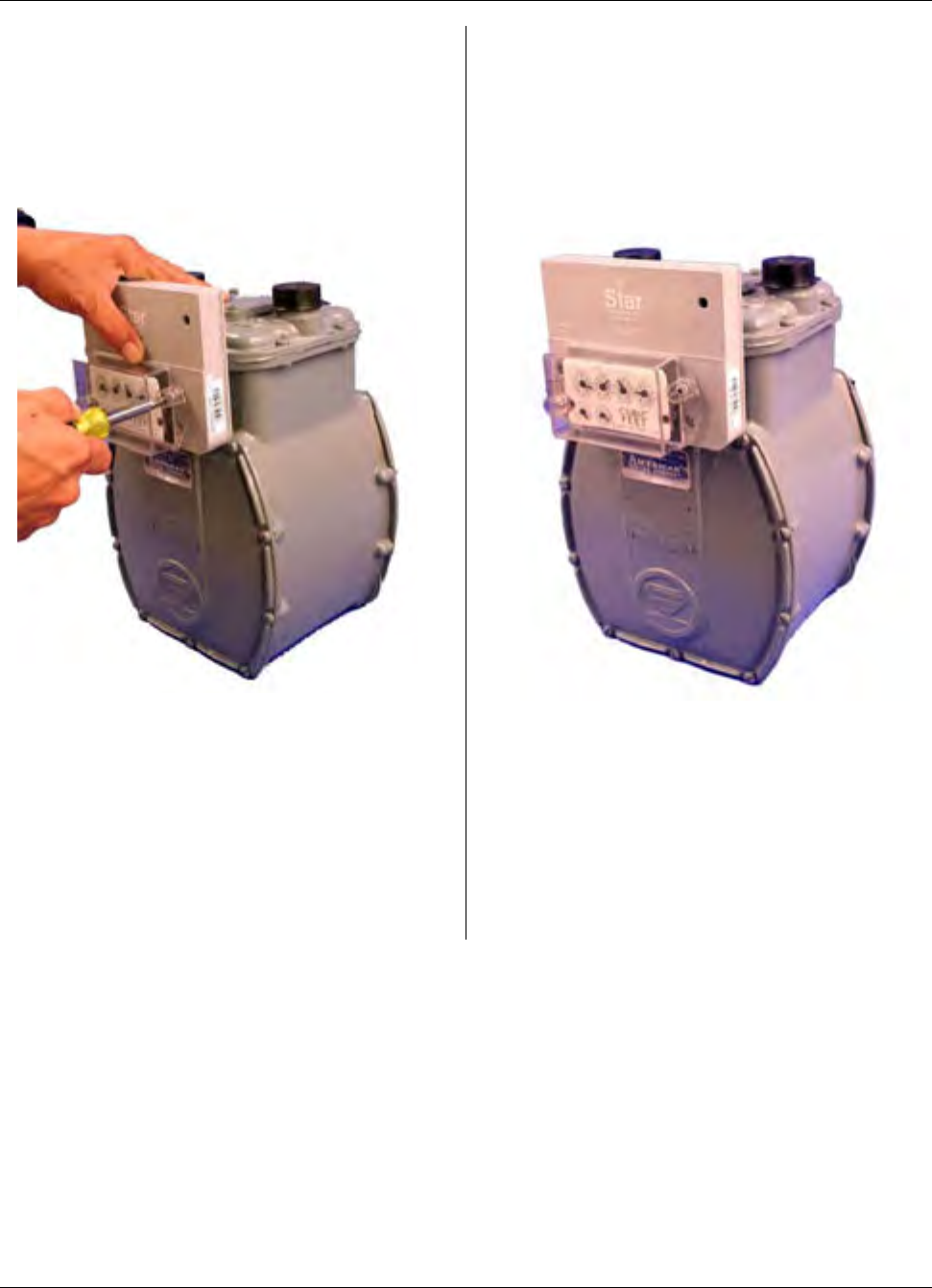
MTU Instruction
for American Meter Company Gas Meters
Step 11 – Now, firmly hand tighten the
two screws to 12 to 15 in-lb. Be careful
not to over tighten the screws. Excessive
torque may damage the MTU enclosure.
Because of this, power tools are not
recommended for this procedure.
Step 12 - Check the coupling one more
time. It should have slight play — it
should not bind or turn too freely.
Step 13 - Place the new cover over the
register so that the top label or arrow is
on top and the vent holes are on the
bottom. Align the cover with the mounting
holes on the MTU, press it into place, and
insert the #10 x 1” screws. Hand tighten
to a torque not to exceed 3-5 inch-
pounds. The gasket should be
compressed slightly.
Step 14 – Replace any anti-tamper,
safety, or security hardware onto the
plastic cover as required.
Step 15 – Once Installation is complete,
program the MTU using your Field
Programmer and the STAR Programmer
Software.
Page 152
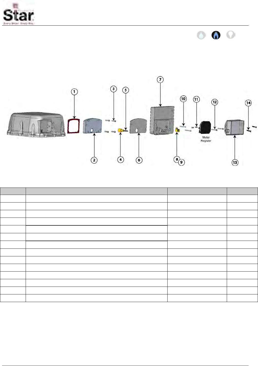
MTU Instruction
for Rockwell/Equimeter/Sensus Gas Meters
471-2035 - 1/14/2008
Purpose & Scope
This instruction provides a procedure for installing a STAR direct-mount MTU on the
Rockwell/Equimeter/Sensus R415 Meters.
Parts Required
Ref. # Item Part Number Quantity
1 Gasket, Adaptor Plate to Meter 066-0032 1
2 Adapter Plate, R415 056-12331C 1
3 10-24 x 3/4” Slotted, Fillister Head Machine Screw, Zinc 069-102424HA 4
4 Coupler, Female, 18 Tooth Gear (orange) 056-12331B 1
5 Coupler Shaft, MTU 056-5155D 1
6 Gasket, Adaptor Plate to MTU 066-12331A 1
7 MTU, Direct Mount 506-7712RO 1
8 18 Tooth Gear, Male, R415 (orange) 056-12331A 1
9 Magnet 036-0002 1
10 ¼-20 x 1 1/4” Slotted, Fillister Head Machine Screw, Zinc 069-142040HA 2
11 #6 Round Spacer, Nylon 068-0051 2
12 #6 x 1 1/4” Combo Panhead Sheet Metal Screw, Zinc 069-060040C3A 2
13 Register Cover, MTU 109-7712A 1
14 #10 x 1” Combo Head Sheet Metal Screw, Zinc 069-100032C3A 2
Page 153

MTU Instruction
for Rockwell/Equimeter/Sensus Gas Meters
Tools Required
To mount the MTU to these meters, you
will need the following tools and
equipment:
• Cordless drill ⅜”, variable
speed, with adjustable torque
settings
• #2 Phillips power screwdriver
bit
• Safety goggles
• Phillips screwdriver
• Slotted screwdriver
• Putty knife
Installation Procedure
Before installing the MTU, anti-tamper,
safety, and security hardware must be
removed from the clear register cover.
Step 1 - Remove the existing clear
register cover by removing the four
screws. Discard the screws and cover.
Step 2 - Remove the register by
removing the two screws. Set the register
aside. Discard the screws.
Step 3 - Remove the existing gasket and
use the putty knife to clean any remnants
of the old gasket from the mating
surfaces.
Step 4 – Insure that the new cork gasket
is properly applied to the meter (ribbed)
side of the adaptor plate and fasten the
adaptor plate and gasket to the meter
using the four 10-24 x ¾” machine screws
provided.
Step 5 – Remove and discard the
existing couplers and shaft from the MTU
and assemble the new couplers and shaft
to the MTU, positioning the female
coupler at the back of the MTU and the
18-tooth gear with magnet at the front as
shown below. Ensure that both couplers
are securely snapped on to the coupler
shaft.
Page 154
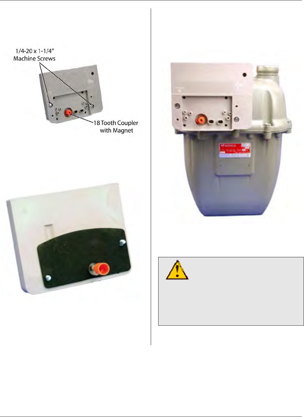
MTU Instruction
for Rockwell/Equimeter/Sensus Gas Meters
Step 6– Insert the two ¼-20 x 1-1/4”
machine screws into the holes on the
MTU as shown.
Step 7 – Turn the MTU over and position
the rubber gasket over the screws and
female coupler as shown.
Step 8 - Position the MTU on the meter,
sliding the female coupler over the drive
gear on the meter. Tighten the MTU
mounting screws to 12 to 15 in-lb.
Check the coupler. It should have slight
play — it should not bind or turn too
freely.
CAUTION!
Do not over tighten screws.
Excessive torque may
damage the MTU enclosure.
Power tools are not
recommended for use on
steps 8-12.
Page 155
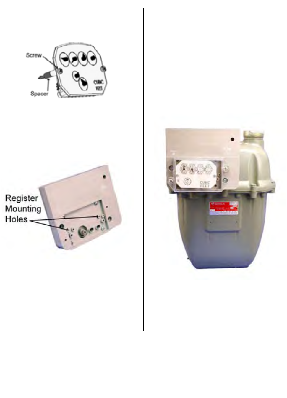
MTU Instruction
for Rockwell/Equimeter/Sensus Gas Meters
Step 9 - On the register, insert the two #6
x 1-1/4” sheet metal screws and spacers
as shown.
Step 10 - Mount the register to the MTU,
fastening it to the mounting holes shown
below. Hand tighten to a torque not to
exceed 3-5 inch-pounds. Make sure the
index register gear and the MTU coupler
gear are engaged.
Step 11 - Place the new cover over the
register so that the top label or arrow is
on top and the vent holes are on the
bottom. Align the cover with the mounting
holes on the MTU, press it into place, and
insert the #10 x 1” screws. Hand tighten
to a torque not to exceed 3-5 inch-
pounds. The gasket should be
compressed slightly.
Step 12 - Replace any anti-tamper,
safety, or security hardware onto the
plastic cover as required.
Step 13 – Once Installation is complete,
program the MTU using the STAR
Programmer Software and your MTU
Programmer.
Page 156
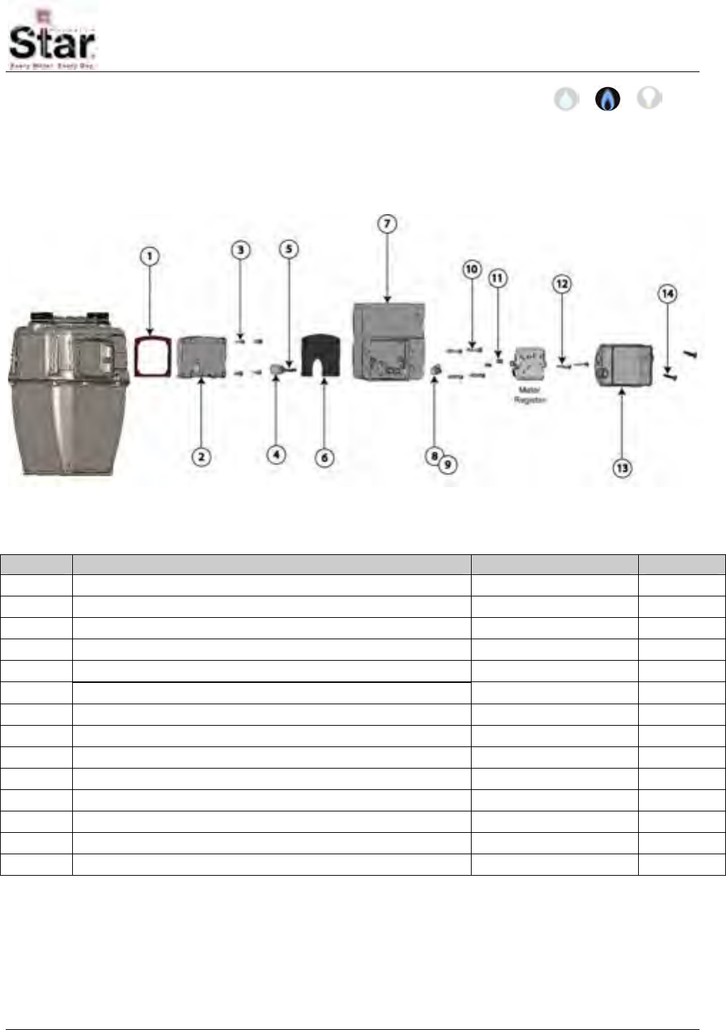
MTU Instruction
for Rockwell/Equimeter/Sensus Gas Meters
471-2036 - 1/14/2008
Purpose & Scope
This instruction provides a procedure for installing a STAR direct-mount MTU on the
following Rockwell/Equimeter/Sensus 175S meters.
Parts Required
Ref. # Item Part Number Quantity
1 Gasket, Adaptor Plate to Meter 066-0032 1
2 Adaptor Plate, 175S 056-12330CC 1
3 10-24 x 1/2” Slotted, Fillister Head Machine Screw, Zinc 069-102416HA 4
4 Coupler, Female, 12 Tooth 175S 056-12330B 1
5 Coupler Shaft, MTU 056-5155D 1
6 Gasket, Adaptor Plate to MTU 066-12330C 1
7 MTU, Direct Mount per project 1
8 12 Tooth Gear, Male, 175S 056-12330A 1
9 Magnet 036-0002 1
10 10-24 x 1-1/8” Slotted, Fillister Head Machine Screw, Zinc 069-102436HA 4
11 #6 Round Spacer, Nylon 068-0051 2
12 #6 x 1 1/4” Combo Head Sheet Metal Screw, Zinc 069-060040C3A 2
13 Register Cover, MTU 109-7712A 1
14 #10 x 1” Combo Head Sheet Metal Screw, Zinc 069-100032C3A 2
Page 157
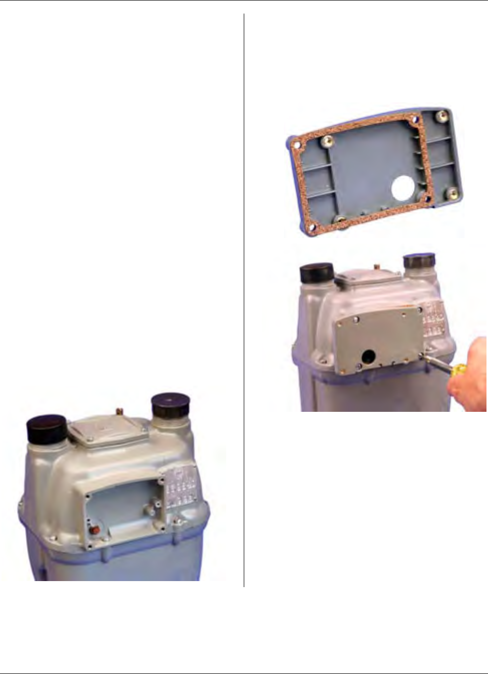
MTU Instruction
for Rockwell/Equimeter/Sensus Gas Meters
Tools Required
To mount the MTU to these meters, you
will need the following tools and
equipment:
• Cordless drill ⅜”, variable
speed, with adjustable torque
settings
• #2 Phillips power screwdriver
bit
• Safety goggles
• Phillips screwdriver
• Slotted screwdriver
Installation Procedure
Before installing the MTU, anti-tamper,
safety, and security hardware must be
removed from the clear register cover.
Step 1 - Remove the existing clear
register cover by removing the four
screws. Discard the screws and cover.
Step 2 - Remove the register by
removing the two screws. Set the register
aside. Discard the screws.
Step 3 – Insure that the cork gasket is
properly applied to the meter (ribbed) side
of the adaptor plate and fasten the
adaptor plate and gasket to the meter
using the four 10-24 x 1/2” machine
screws provided.
Page 158
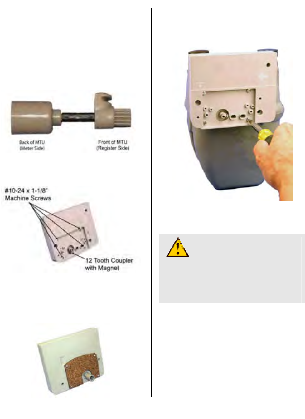
MTU Instruction
for Rockwell/Equimeter/Sensus Gas Meters
Step 4 – Remove and discard the
existing couplers and shaft from the MTU
and assemble the new couplers and shaft
to the MTU, positioning the female
coupler at the back of the MTU and the
12-tooth gear with magnet at the front as
shown below. Ensure that both couplers
are securely snapped on to the coupler
shaft.
Step 5 – Insert the four #10-24 x 1-1/8”
machine screws into the holes at the
corners of the index box as shown.
Step 6 – Turn the MTU over and position
the rubber gasket over the screws and
female coupler as shown. The cork side
of the gasket should face out as shown
below.
Step 7 - Position the MTU on the meter,
sliding the female coupler over the drive
gear on the meter. Tighten the MTU
mounting screws to 12 to 15 in-lb.
Check the coupler. It should have slight
play — it should not bind or turn too
freely.
CAUTION!
Do not over tighten screws.
Excessive torque may
damage the MTU enclosure.
Power tools are not
recommended for use on
steps 8-12.
Page 159
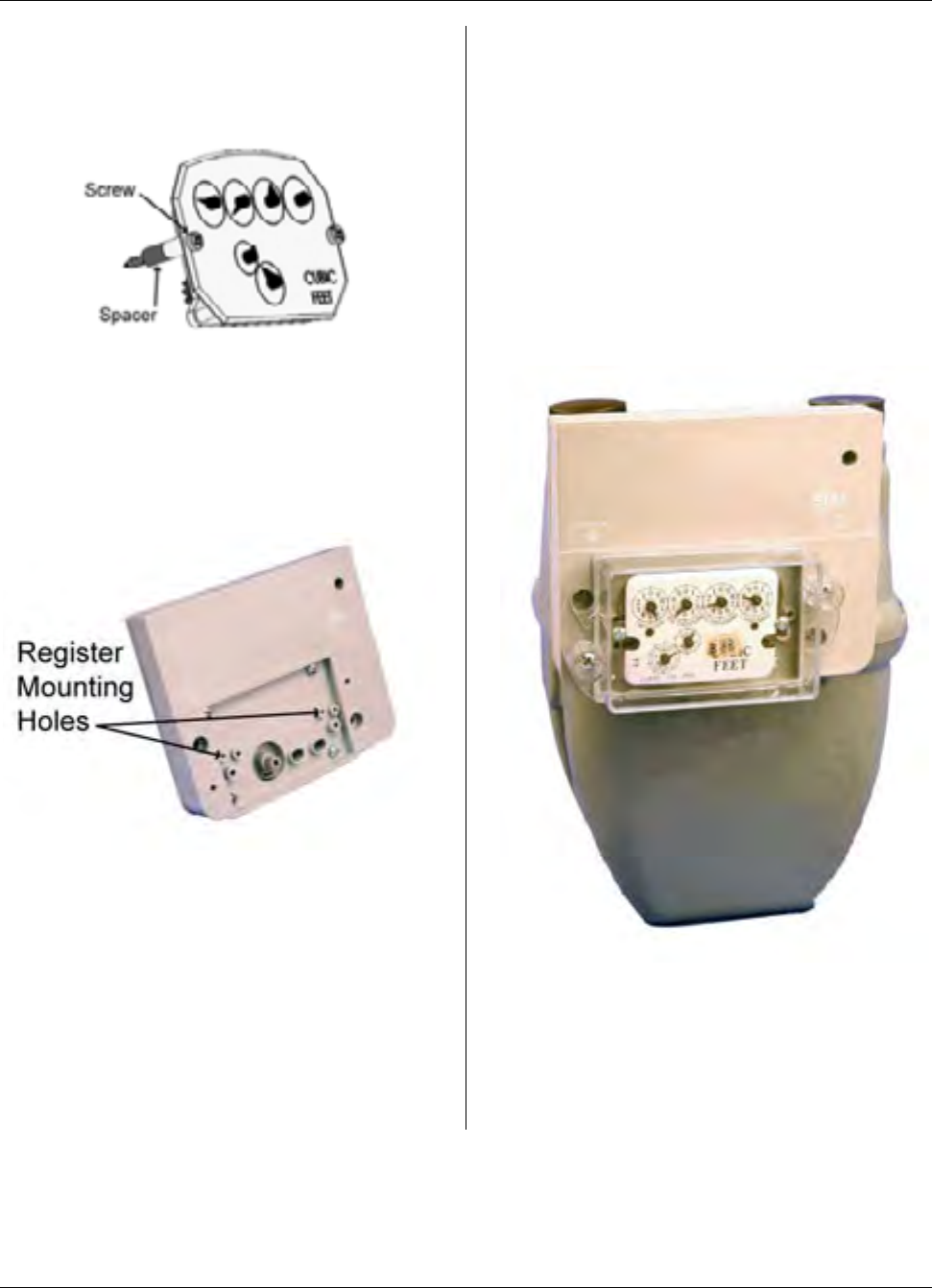
MTU Instruction
for Rockwell/Equimeter/Sensus Gas Meters
Step 8 - On the register, insert the two #6
x 1-1/4” sheet metal screws and spacers
as shown.
Step 9 - Mount the register to the MTU,
fastening it to the mounting holes shown
below. Hand tighten to a torque not to
exceed 3-5 inch-pounds. Make sure the
index register gear and the MTU coupler
gear are engaged.
Step 10 - Place the new cover over the
register so that the top label or arrow is
on top and the vent holes are on the
bottom. Align the cover with the mounting
holes on the MTU, press it into place, and
insert the #10 x 1” screws. Hand tighten
to a torque not to exceed 3-5 inch-
pounds. The gasket should be
compressed slightly.
Step 11 - Replace any anti-tamper,
safety, or security hardware onto the
plastic cover as required.
Step 12 – Once Installation is complete,
program the MTU using the STAR
Programmer Software and your MTU
Programmer.
Page 160
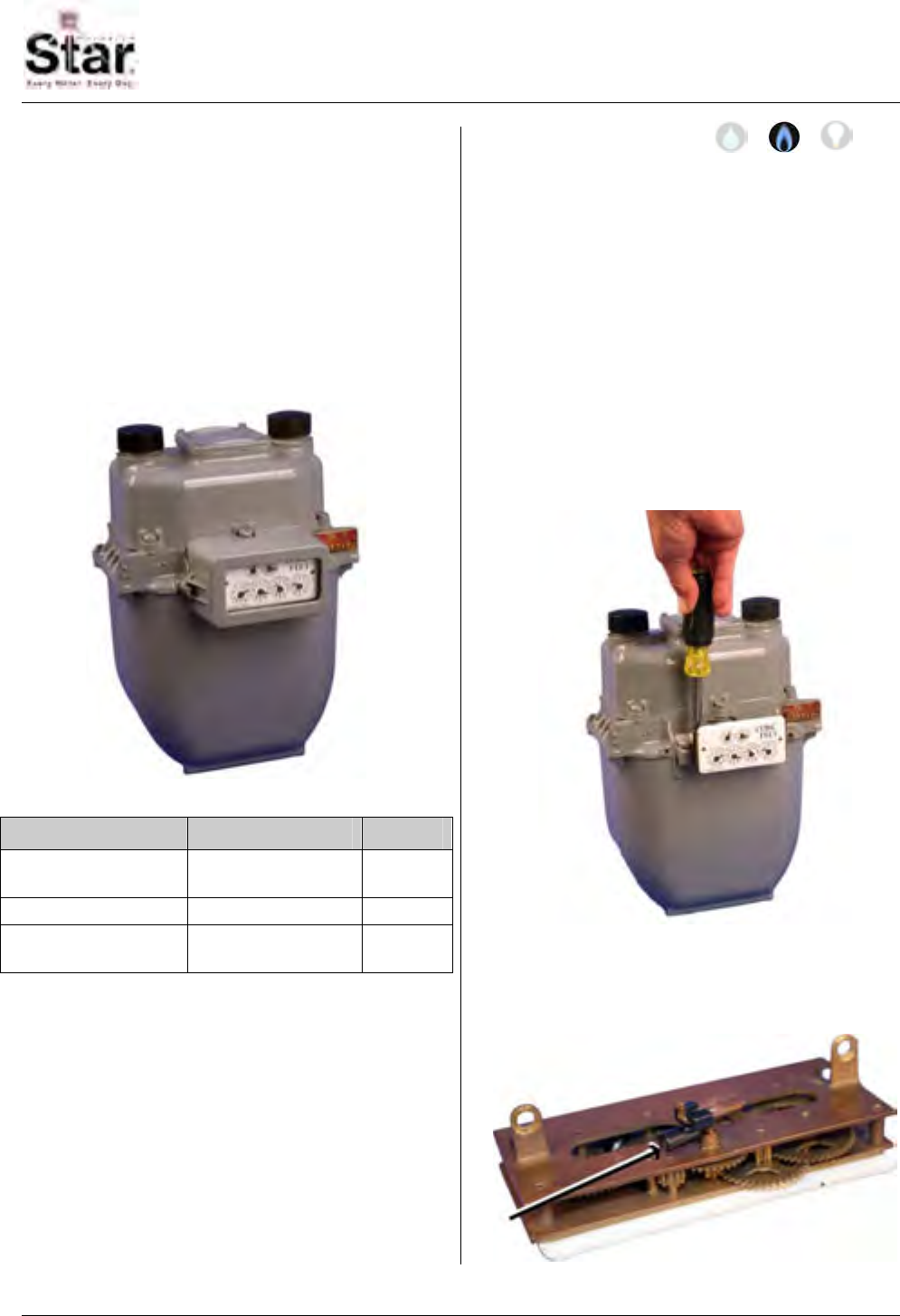
MTU Instruction
for Rockwell 175-EMCO Gas Meters
Purpose & Scope
This instruction provides a procedure for
use in installing a Hexagram STAR MTU
on a Rockwell 175-EMCO Gas Meter.
Please also refer to Publication 471-
2000, General Installation and Wiring
Guidelines for general information
covering the wiring and mounting of
STAR MTUs.
Parts Required
Item Part Number Qty
Magnet Clip
with Magnet 056-12469A 1
Sensor Clip 056-12469B 1
MTU/Sensor
Assembly 506-7712BRO1 1
Tools Required
• Screwdriver, #2 Phillips
• Screwdriver, 1/4” slotted (flat-
blade)
• Round file
Also see Publication 471-2000, General
Installation and Wiring Guidelines for a
complete list of recommended tools and
supplies for MTU Installation.
Installation Procedure
Step 1 – If necessary, remove any anti-
tamper seals or security hardware from
the index cover.
Step 2- Loosen and remove the two
screws securing the index cover to the
meter. Set the screws and the index
cover aside. These items will be reused
during reassembly.
Step 3 – Remove the index by removing
the two screws securing the index to the
meter. Set the screws aside.
Step 4 – Turn the index over and slide
the magnet clip onto the index drive dog
as shown. Slide the clip onto the drive
dog until it snaps into place.
471-2037 - 4/28/2008
Page 161
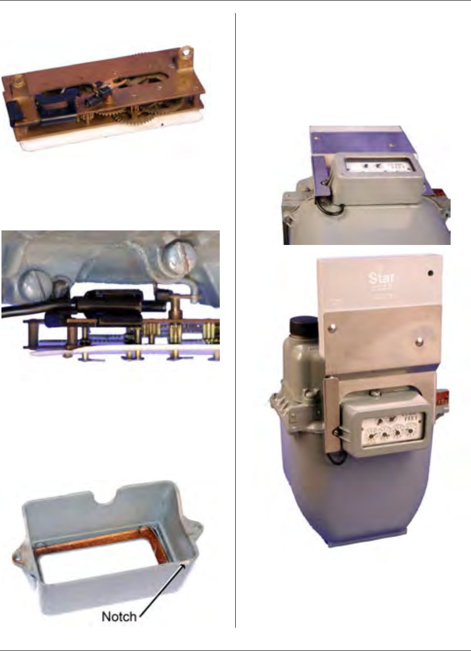
MTU Instruction
for Rockwell 175-EMCO Gas Meters
Step 5 – Snap the sensor clip onto the
back of the index as shown.
Step 6 – Position the index on the meter
and attach the index using the index
mounting screws removed in Step 3.
Ensure that the meter drive engages the
index drive dog as shown below.
Step 7 – Snap the sensor of the MTU into
the sensor clip as shown.
Step 8 – Using a round file, file a 1/8”
notch .on the lower left corner of the rim
of the index cover. This notch will provide
an exit for the sensor wire.
Step 9 – Route the sensor cable to the
left of the index and position the MTU and
index cover on the meter aligning the
sensor cable with the notch in the meter
body at the bottom left of the index cover.
Fasten the MTU and index cover to the
meter using the original screws removed
in Step 2.
Step 10 – Installation is now complete.
Program the MTU using the STAR
Programmer Software and your Field
Programmer.
Page 162
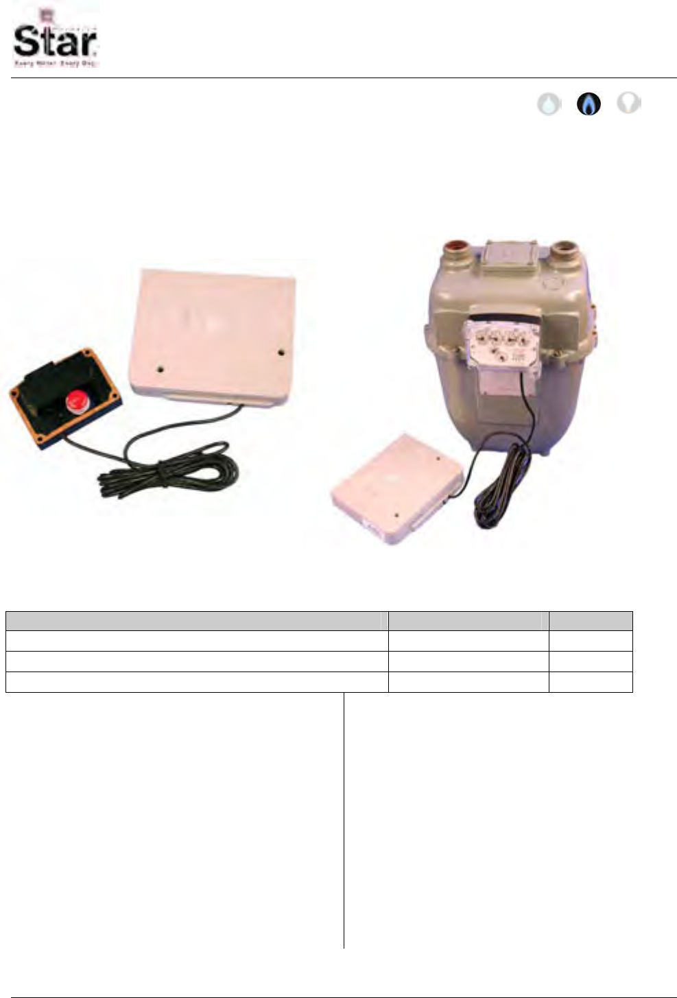
MTU Instruction
for Rockwell/Equimeter/Sensus Gas Meters
Purpose & Scope
This instruction provides a procedure for installing a STAR remote-mount MTU on the
following Rockwell/Equimeter/Sensus meters: R175, R200, R250, R275, R310, R315,
RT210. Please also refer to Publication 471-2000, General Installation and Wiring
Guidelines for general information covering the wiring and mounting of STAR MTUs.
Parts Required
Item Part Number Quantity
MTU, Rockwell Remote Mount, with sensor per project 1
#6 x 3/4” Philips Panhead Sheet Metal Screw 069-06000242A 2
#10-24 x 1-1/2” Slotted, Fillister Head Machine Screw 069-102448HA 4
Tools Required
To mount the MTU to these meters, you
will need the following tools and
equipment:
• Safety goggles
• Phillips screwdriver
• Slotted screwdriver
Installation Procedure
Before installing the MTU, anti-tamper,
safety, and security hardware must be
removed from the clear register cover.
Step 1 - Remove the existing clear
register cover by removing the four
screws that hold it. Set the cover aside.
Discard the screws.
Step 2 - Remove the register by
removing the two screws. Discard the
screws.
471-2038 - 7/18/2007
Page 163
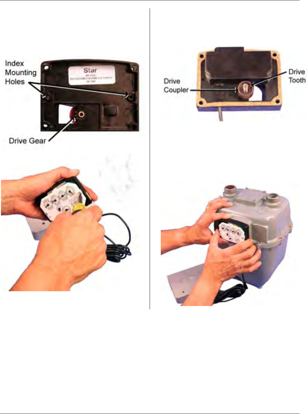
MTU Instruction
for Rockwell/Equimeter/Sensus Gas Meters
Step 3 – Position the register on the front
of the sensor assembly, aligning the drive
gear with the index drive. Mount the
index to the sensor assembly using the
two #6 x 3/4” screws provided.
Step 4 – Carefully remove the protective
cap from the drive coupler on the rear of
the sensor assembly. Note the tooth on
the inner surface of the coupler.
Step 5 - Position the sensor on the meter.
so that the tooth on the coupler engages
with the teeth on meter’s index drive gear.
If engaged correctly, the cork gasket on
the sensor will fit flush against the surface
of the index box.
Page 164
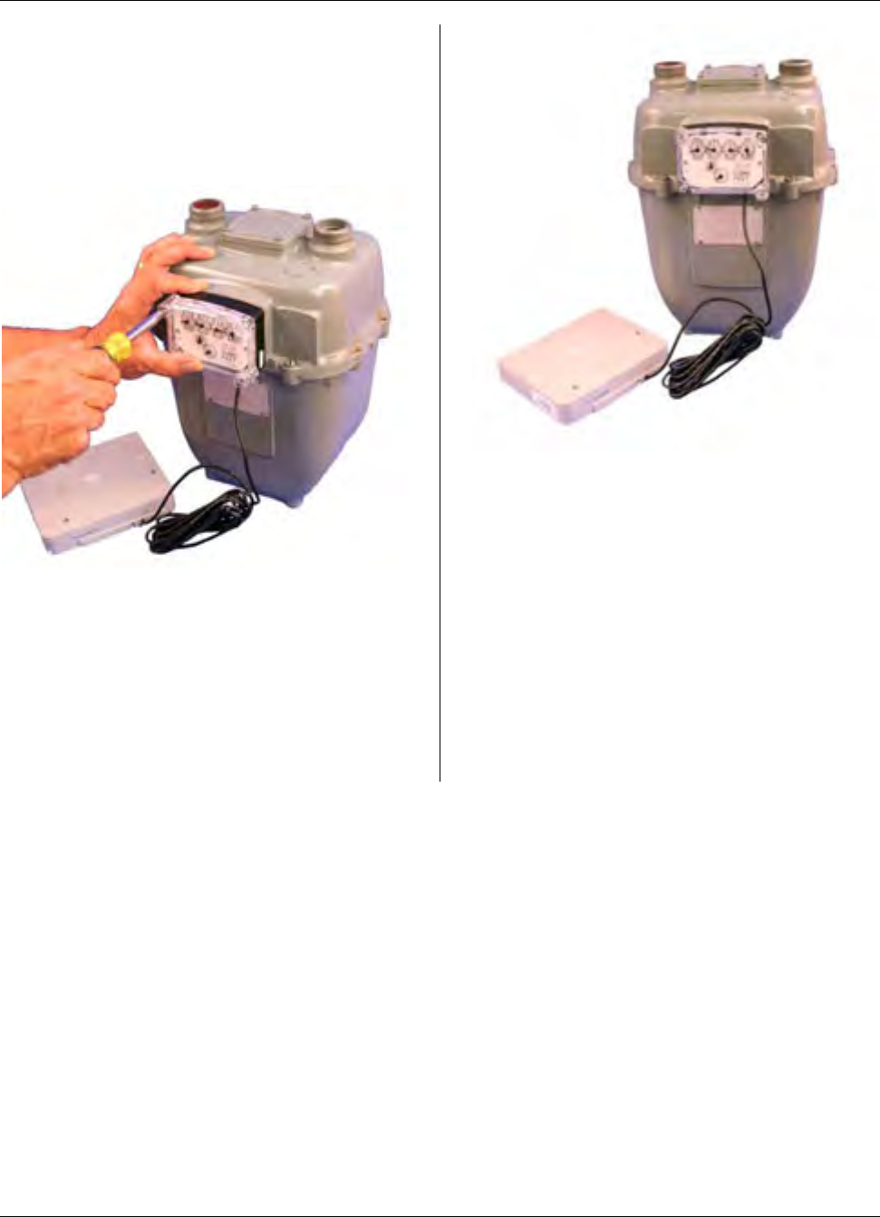
MTU Instruction
for Rockwell/Equimeter/Sensus Gas Meters
Step 6 – Position the clear register cover
on the front of the sensor and fasten the
assembly to the meter using the four 10-
24 x 1-1/2” screws provided. Hand
tighten these screws to a torque not to
exceed 12-15 inch pounds.
Step 8 – Mount the MTU, following the
wiring and mounting guidelines outlined in
Publication 471-2000, General
Installation and Wiring Guidelines. If
necessary, the MTU cable can be
extended up to 500 feet.
Step 7 - Replace any anti-tamper, safety,
or security hardware onto the plastic
cover as required. Step 9 – Once Installation is complete,
program the MTU using your Field
Programmer and the STAR Programmer
Software.
Page 165

MTU Instruction
for Rockwell/Equimeter/Sensus Gas Meters
Intentionally Left Blank
Page 166
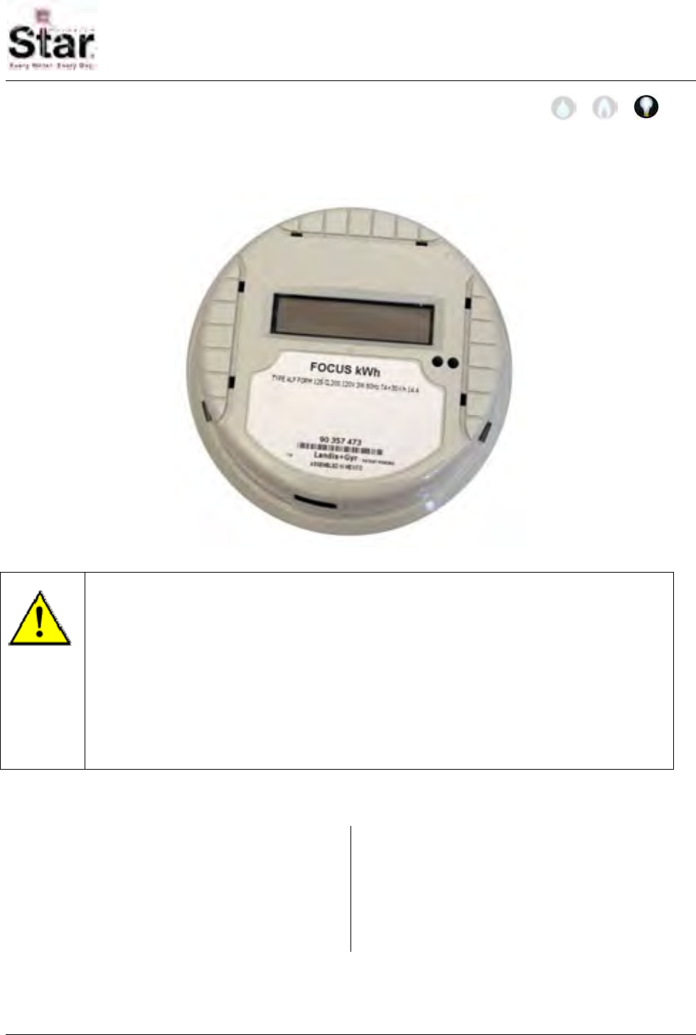
MTU Instruction
for Landis & Gyr Focus MTU/Electric Meter Assembly
Purpose & Scope
This instruction provides a procedure for installing Landis & Gyr Focus MTU/Electric
Meter Assemblies.
WARNING!
Be sure to follow all applicable electrical codes, standards and safety
procedures during all phases of operation, service and repair of this device.
Any work on energized meters and meter sockets presents a danger of
electrical shock. Meter socket terminals carry the full incoming service
voltage. Touching these terminals may result in death or serious injury.
The information contained in this document is intended to be an aid to
qualified metering personnel. It is not intended to replace the extensive
training necessary to handle metering equipment in a safe manner.
Supplies and Tools Required
Physical Installation of the Landis & Gyr
Focus MTU/Electric Meter Assemblies
into compatible meter sockets can be
accomplished without the use of tools.
Testing of the meter socket, however,
may require specialized equipment.
Check with the local electric utility for
required testing procedures.
471-2040 – 2/13/2007
Page 167
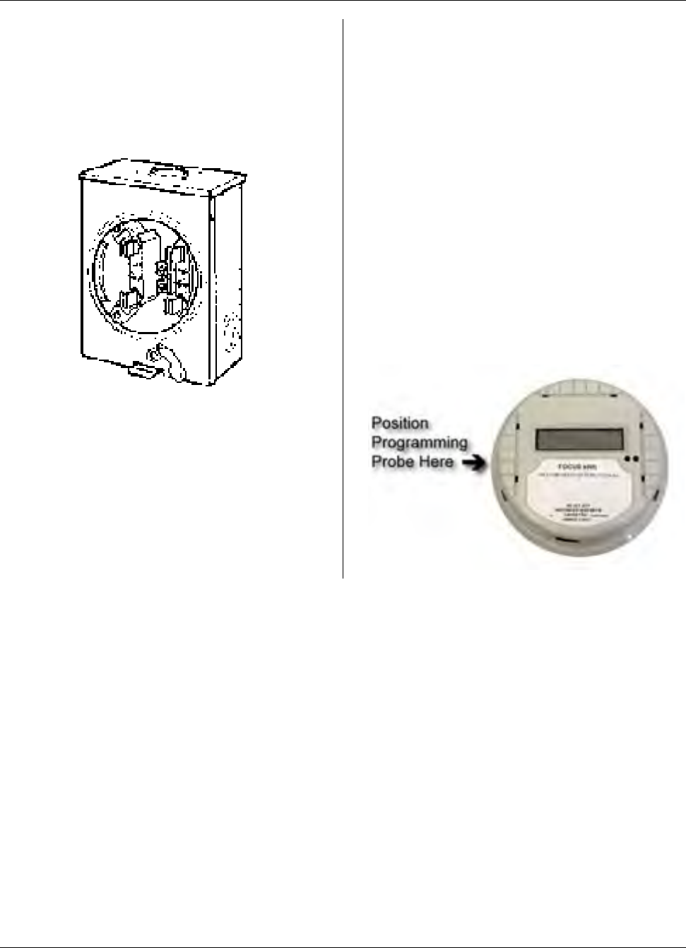
MTU Instruction
for Landis & Gyr Focus MTU/Electric Meter Assembly
Installation Procedure
Step 1 – Complete all test procedures
required by the local electric utility and
verify that the meter socket has been
correctly installed and wired.
Step 2 – If applicable, remove the
existing meter assembly from the meter
socket.
Step 3 – Place the meter/MTU assembly
into the meter socket, carefully aligning
the contact blades with the corresponding
jaws in the meter base.
Step 4 – Make a final visual inspection to
ensure that the meter/MTU assembly is
seated, sealed properly, and receiving
power.
Step 5 – Installation is now complete,
program the MTU using the STAR
Programmer Software and your Field
Programmer.
When programming the integral MTU
mounted in this meter, hold the
programming coil at the 9 o’clock position
as shown here.
Page 168
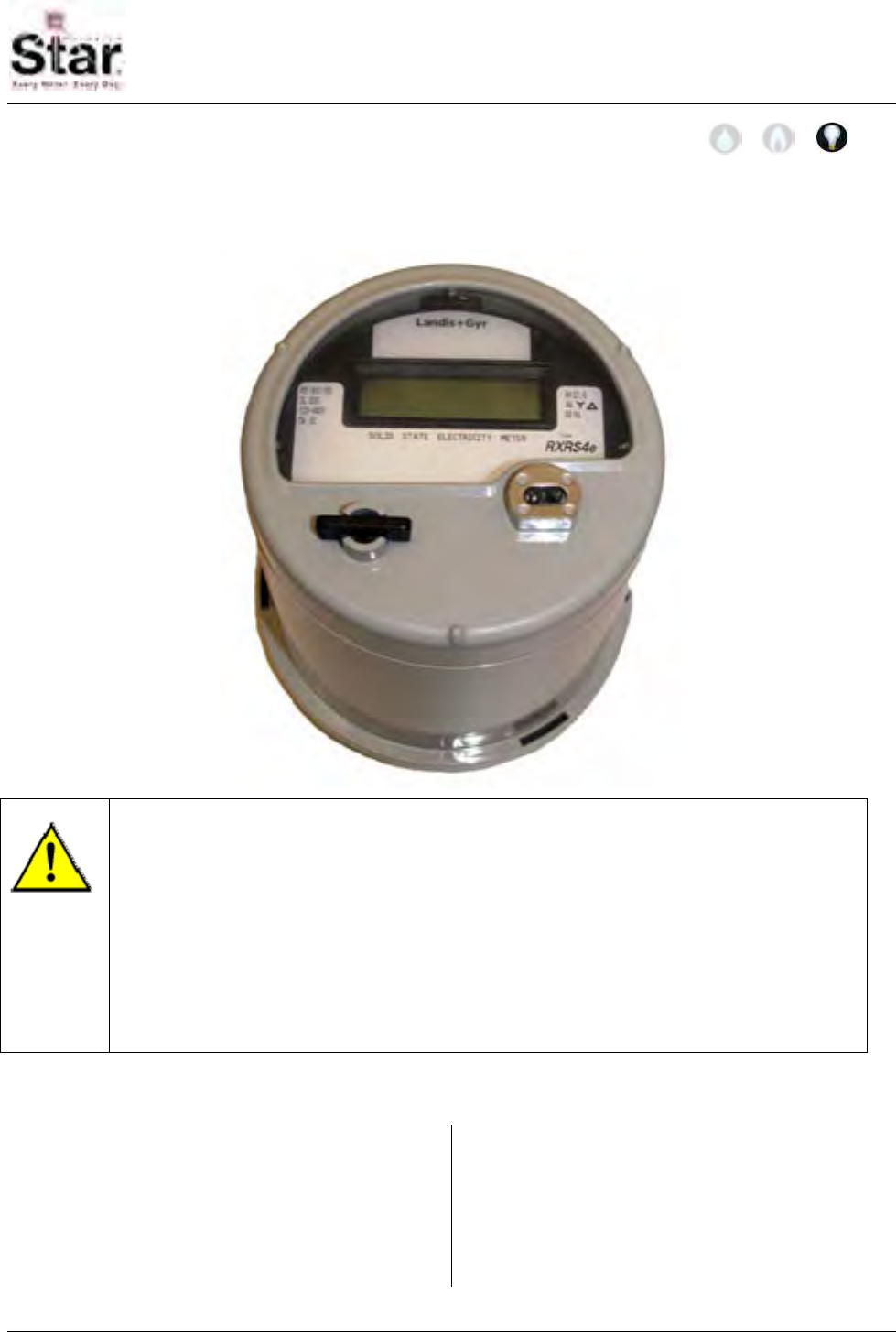
MTU Instruction
for Landis & Gyr S4 MTU/Electric Meter Assembly
Purpose & Scope
This instruction provides a procedure for installing Landis & Gyr S4 MTU/Electric Meter
Assemblies.
WARNING!
Be sure to follow all applicable electrical codes, standards and safety
procedures during all phases of operation, service and repair of this device.
Any work on energized meters and meter sockets presents a danger of
electrical shock. Meter socket terminals carry the full incoming service
voltage. Touching these terminals may result in death or serious injury.
The information contained in this document is intended to be an aid to
qualified metering personnel. It is not intended to replace the extensive
training necessary to handle metering equipment in a safe manner.
Supplies and Tools Required
Physical Installation of the Landis & Gyr
S4 MTU/Electric Meter Assemblies into
compatible meter sockets can be
accomplished without the use of tools.
Testing of the meter socket, however,
may require specialized equipment.
Check with the local electric utility for
required testing procedures.
471-2041 – 2/13/2007
Page 169
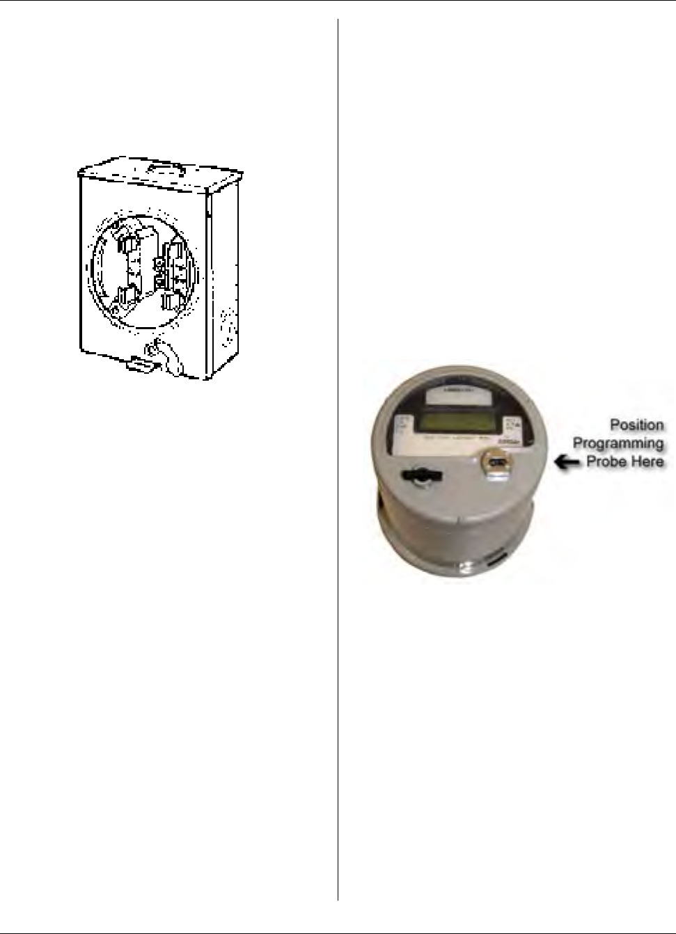
MTU Instruction
for Landis & Gyr S4 MTU/Electric Meter Assembly
Installation Procedure
Step 1 – Complete all test procedures
required by the local electric utility and
verify that the meter socket has been
correctly installed and wired.
Step 2 – If applicable, remove the
existing meter assembly from the meter
socket.
Step 3 – Place the meter/MTU assembly
into the meter socket, carefully aligning
the contact blades with the corresponding
jaws in the meter base.
Step 4 – Make a final visual inspection to
ensure that the meter/MTU assembly is
seated, sealed properly, and receiving
power.
Step 5 – Installation is now complete,
program the MTU using the STAR
Programmer Software and your Field
Programmer.
When programming the integral MTU
mounted in this meter, hold the
programming probe at the 3 o’clock
position as shown here.
Page 170

MTU Instruction
for DFW Rectangular Composite Pit Lids
Purpose & Scope
This instruction provides a procedure for mounting a New Flatpak STAR MTU to a
rectangular DFW composite pit lid. This procedure does not detail the wiring of the MTU
to the meter that may be encountered inside of the pit. Please refer to Publication 471-
2000, General Installation and Wiring Guidelines in addition to any meter specific MTU
installation and programming instructions.
Parts Required
Item Part Number Quantity
MTU As required for installed
meter 1
Long Spacers (for pit lid mounting of New Style Flatpak
MTUs) 056-8150L 2 per MTU
installation
#10 x 2 1/2” Phillips Pan Head Type AB Stainless Steel
Sheet Metal Screw 2 per MTU
installation
Tools Required
To mount the MTU to these DFW pit lids,
you will need the following tools and
equipment:
• Safety goggles
• #3 Phillips driver bit
• 3/32” drill bit
• Cordless Drill 3/8”, variable speed,
with adjustable torque settings.
Note on setting the torque range: On a
drill-driver that has about 20 settings
(positions), set the adjustment to #6. Use
the lower speed range of the drill-driver.
This should amount to approximately 8 in-
lbs of torque. Reference the operating
instructions for your particular drill to
more accurately determine what setting to
use to achieve a torque range of
approximately 8 in-lbs.
471-2042 - 11/9/2006
Page 171
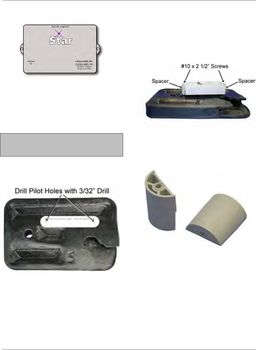
MTU Instruction
for DFW Rectangular Composite Pit Lids
Installation Procedure
Mounting a New Flatpak STAR MTU to
a rectangular DFW composite pit lid.
Step 1 – Place the lid top down and use a
template to mark and drill two pilot holes
in the bottom surface of the pit lid as
shown below.
Note: A paper template is included in this
document. The spacing between the two
holes must be 6.81” (6 13/16”).
The pilot holes should be along the solid
ridge running across the pit lid as shown,
positioned away from the finger hole.
Step 2 - Place plastic spacers under the
mounting tabs on the MTU as shown
below, and attach the MTU to the pit lid
with the 2 ½” stainless sheet metal
screws. Insert the screws through the
mounting holes and spacers and into the
pre-drilled pilot holes.
Be sure to use the long spacers
(Hexagram Part Number 056-8150L).
You will note that one end of the spacers
has a semi-circular ridge that mates with
the mounting tabs on the MTU.
Page 172
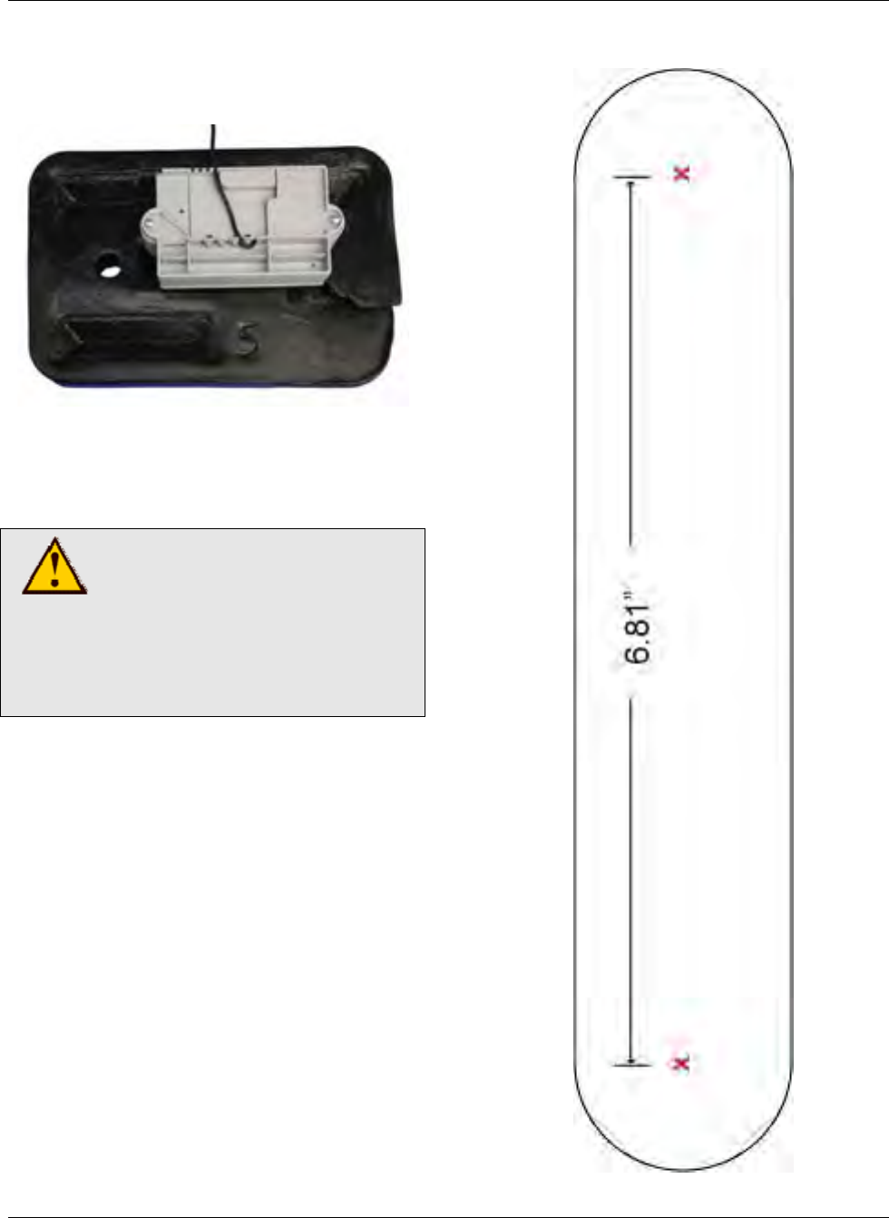
MTU Instruction
for DFW Rectangular Composite Pit Lids
Be sure to position the MTU as shown,
with the top (antenna) section of the MTU
positioned in the approximate center of
the lid.
Torque screws to approximately 8 in-lbs.
The MTU should be snug and suspended
by the spacers above the bottom surface
of the pit lid by approximately ½”.
CAUTION!
Be sure to follow all General
Guidelines outlined in
Publication 471-2000 along
with the specific wiring
instructions for the meter
being used.
Step 3 – Wire the MTU to the meter,
making sure that the wire is routed so that
it does not become pinched when the lid
is closed.
Step 4 - Installation is now complete. You
can now proceed to program the MTU
using the STAR Programmer Software
and your MTU Programmer.
Template
Page 173

MTU Instruction
for DFW Rectangular Composite Pit Lids
Intentionally Left Blank
Page 174
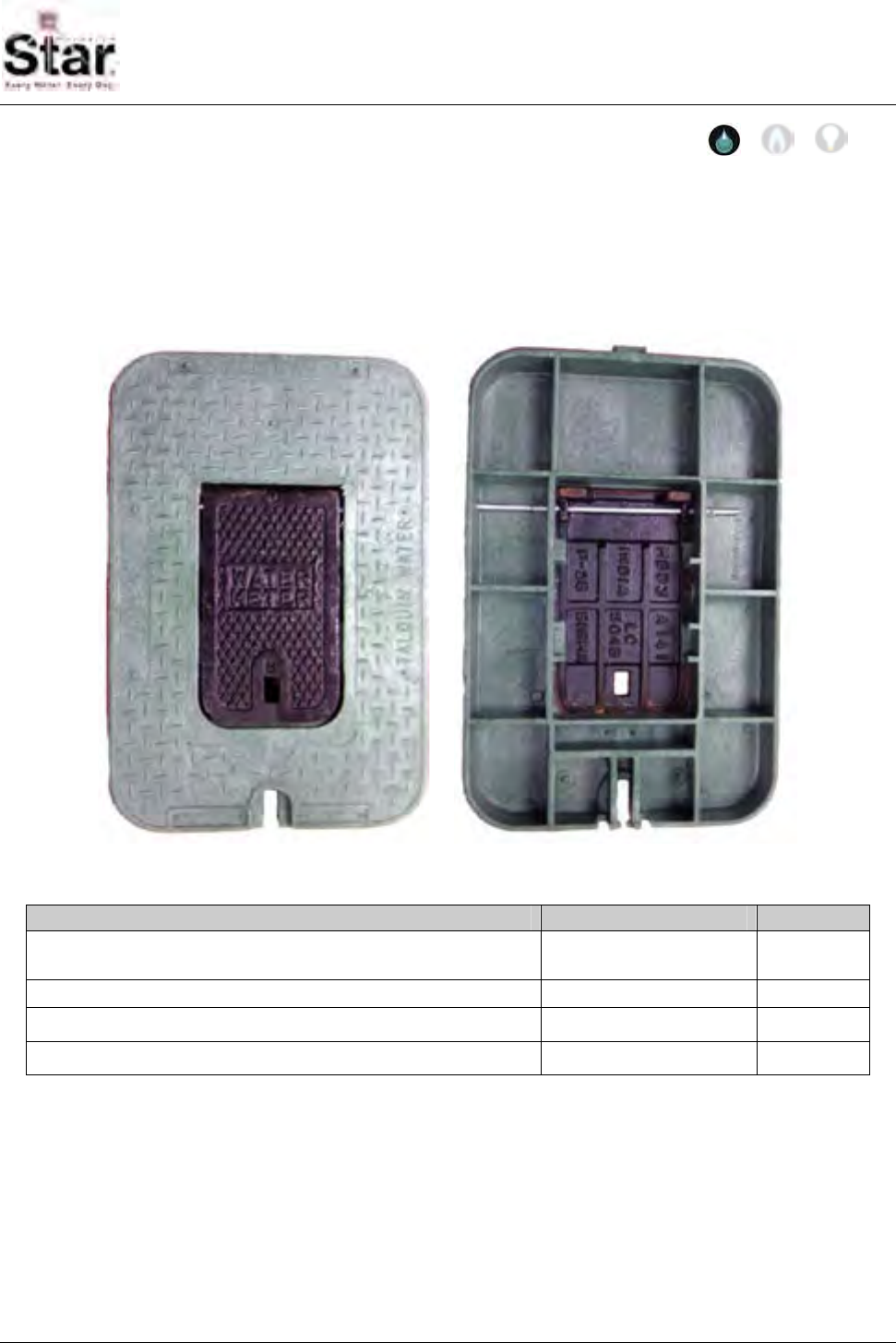
MTU Instruction
for Carson Industries 1015-5 Pit Lids
471-2043 - 3/27/2009
Purpose & Scope
This instruction provides a procedure for mounting a STAR Flatpak MTU to a Carson
Industries Polyplastic Model 1015-5 pit lid. This procedure does not detail the wiring of
the MTU to the meter that may be encountered inside of the pit. Please refer to
Publication 471-2000, General Installation and Wiring Guidelines in addition to any meter
specific MTU installation and programming instructions.
Parts Required
Item Part Number Quantity
MTU Flatpack - Model 8150 As required for
installed meter 1
Long Plastic Zip Ties Source locally 2
Electric Drill Source locally 1
¼” Drill Bit Source locally 1
Page 175
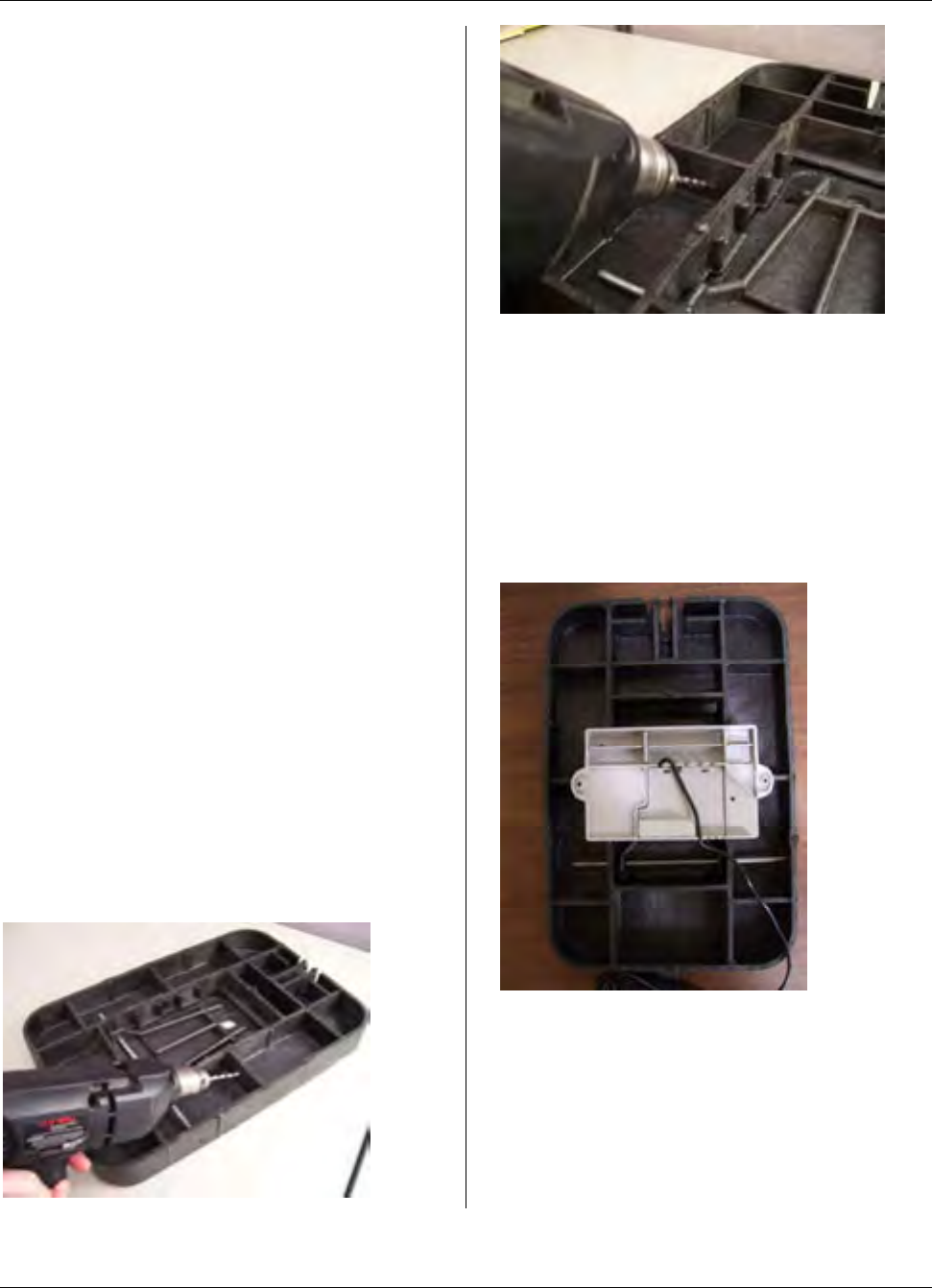
MTU Instruction
for Carson Industries 1015-5 Pit Lids
Tools Required
To mount the MTU to the Carson pit lids,
you will need the following tools and
equipment:
• Safety goggles
• Long plastic zip ties
• 1/4” standard drill bit
• Cordless Drill with variable speed
and adjustable torque settings
Note on setting the torque range: On a
drill that has about 20 settings (positions),
set the adjustment to #6. Use the lower
speed range of the drill. This should
amount to approximately 8 in-lbs of
torque. Reference the operating
instructions for your particular drill to
more accurately determine what setting to
use to achieve a torque range of
approximately 8 in-lbs.
Installation Procedure
Step 1 – Drill a hole through the left and
right center ribs of the pit lid. The hole
should be approximately one inch from
the center of the lid and about ½ inch
from the top of the rib.
Step 2 – Position the MTU with the label
side face down against the underside of
the pit lid. The mounting tabs of the MTU
should be aligned with the center ribs with
the newly drilled holes. Ensure that the
metal hinge of the pit lid view door is
below the bottom of the MTU.
Page 176
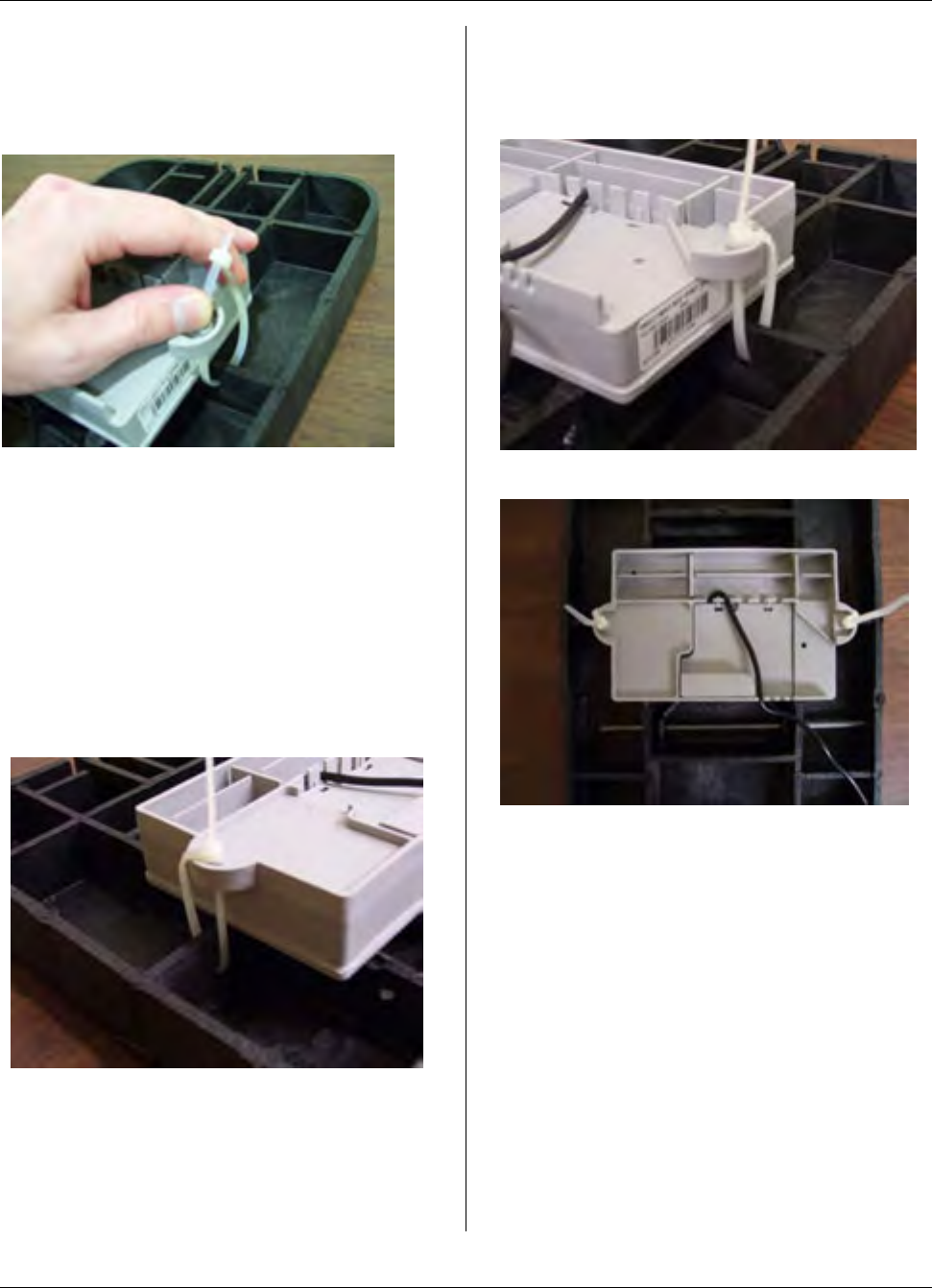
MTU Instruction
for Carson Industries 1015-5 Pit Lids
Step 3 – Thread plastic zip ties through
each of the drilled rib holes and through
the holes of the MTU mounting tabs.
Step 4 – Gently pull through the zip ties
so that the MTU is secured to the pit lid.
Do not over tighten the zip ties.
Excessive torque may bend the
mounting tabs and break the seal of
the MTU. There should be a little
movement with the MTU once the zip ties
have been sufficiently tightened.
Step 5 – Once secured, remove the
unnecessary length from the zip tie ends.
Page 177
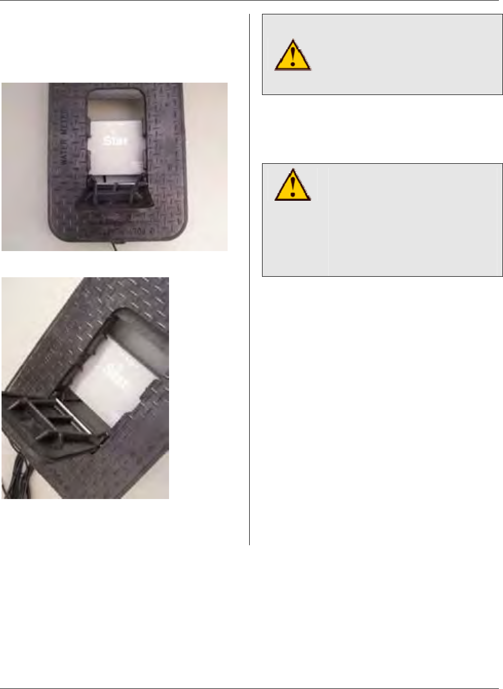
MTU Instruction
for Carson Industries 1015-5 Pit Lids
Step 6 – The MTU STAR logo should be
visible through the pit lid view door after
proper placement and mounting.
CAUTION!
Do not over tighten the zip ties
when mounting the MTU.
Excessive torque can bend
the MTU mounting tabs.
CAUTION!
Be sure to follow all General
Guidelines outlined in
Publication 471-2000 along
with the specific wiring
instructions for the meter
being used.
Step 7 – Wire the MTU to the meter,
folding and forming wires into valve box
as necessary so that they do not interfere
with lid locking mechanism and cannot
become pinched.
Step 8 – Installation is now complete.
You can now proceed to program the
MTU using the STAR Field Programmer
Software and your Field Programmer.
Page 178

MTU Instruction
for Rockwell/Equimeter/Sensus Gas Meters
Purpose & Scope
This instruction provides a procedure for installing a STAR direct-mount MTU on
Rockwell/Equimeter/Sensus MR-8 residential gas meters.
Parts Required
Ref. # Item Part Number Quantity
1 Gasket 066-5155C 1
2 Coupler, MTU 056-13183A 1
3 Retaining Shaft, MTU 056-5155D 1
4 MTU, Direct Mount 501-6327/7712 1
5 Magnet 036-0002 1
6 Gear/magnet holder 056-13183B 1
7 10-24 x 1 1/8” Slotted, Fillister Head Machine Screw 069-102436HA 4
8 #6 Round Spacer, Nylon 068-60812-EX 2
9 #6 x 1 1/4” Combo Panhead Sheet Metal Screw 069-060040C3A 2
10 Register Cover, MTU 109-7712A 1
11 #10 x 1” Combo Panhead Sheet Metal Screw 069-100032C3A 2
471-2044 - 4/8/2007
Page 179
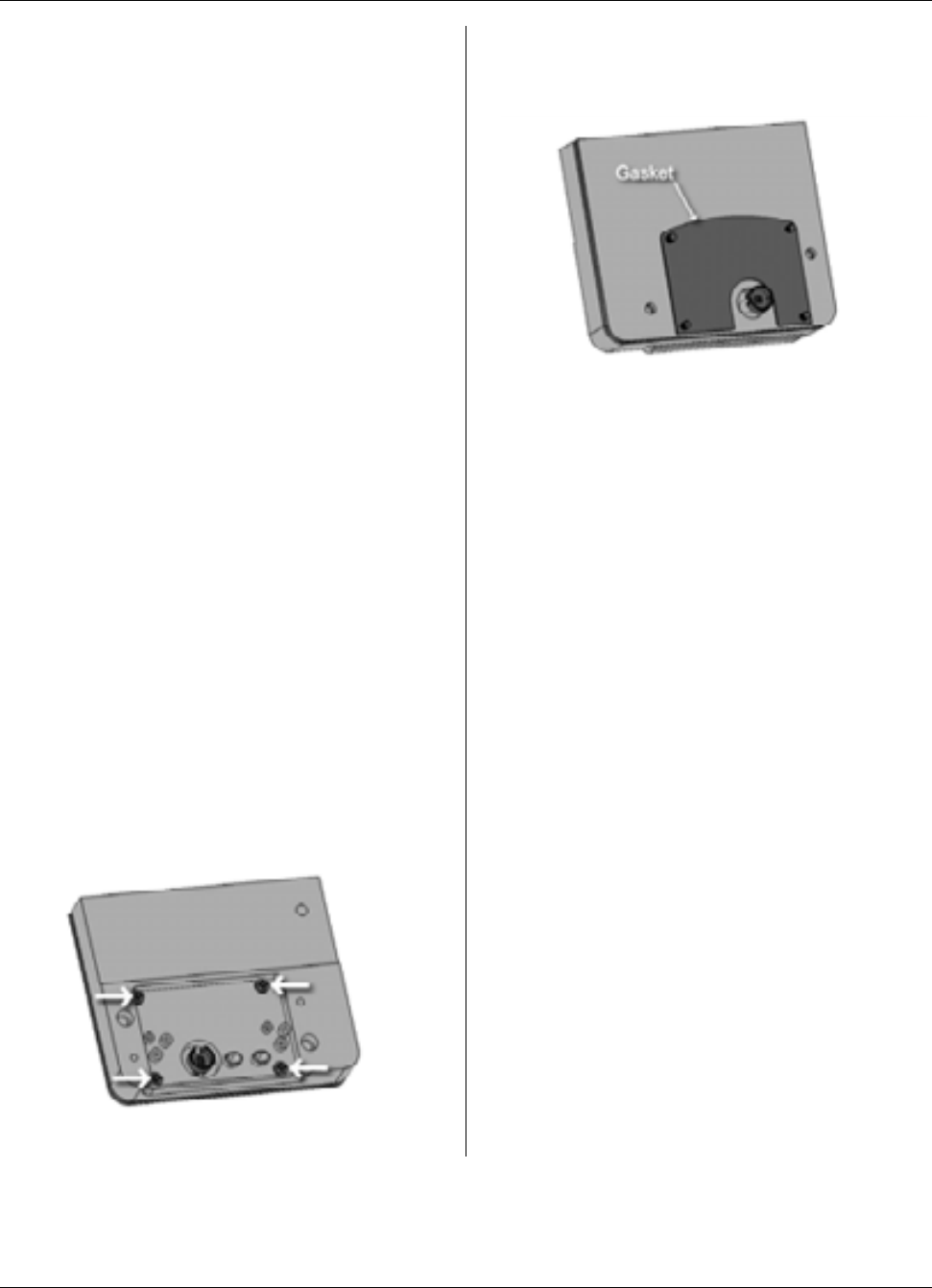
MTU Instruction
for Rockwell/Equimeter/Sensus Gas Meters
Tools Required
To mount the MTU to these meters, you
will need the following tools and
equipment:
• Cordless drill ⅜”, variable
speed, with adjustable torque
settings
• #2 Phillips power screwdriver
bit
• Safety goggles
• Phillips screwdriver
• Slotted screwdriver
Installation Procedure
Before installing the MTU, anti-tamper,
safety, and security hardware must be
removed from the clear register cover.
Step 1 - Remove the existing clear
register cover by removing the four
screws. Discard the screws and cover.
Step 2 - Remove the register by
removing the two screws. Set the register
aside. Discard the screws.
Step 3 - Insert the four 10-24 x 1⅛”
screws through the holes on the MTU as
shown.
Step 4 – Turn the MTU over and place
the gasket on the back of the MTU so that
it aligns over the four screws, as shown.
Step 5 - Position the MTU on the meter.
Rotate the coupler so that the gear tooth
on the coupler engages with the gear
teeth on the gas meter. Orientation is not
critical, but you should be able to feel the
teeth “bite” when you turn the coupler
from the front of the MTU.
Step 6 - Tighten the four 10-24 x 1-⅛”
screws to 12 to 15 in-lb. On a standard
drill driver with 0 to 24 torque settings,
this is typically the #10 setting. Tighten
corner to corner.
Step 7 - Check the coupler. It should
have slight play — it should not bind or
turn too freely.
Page 180
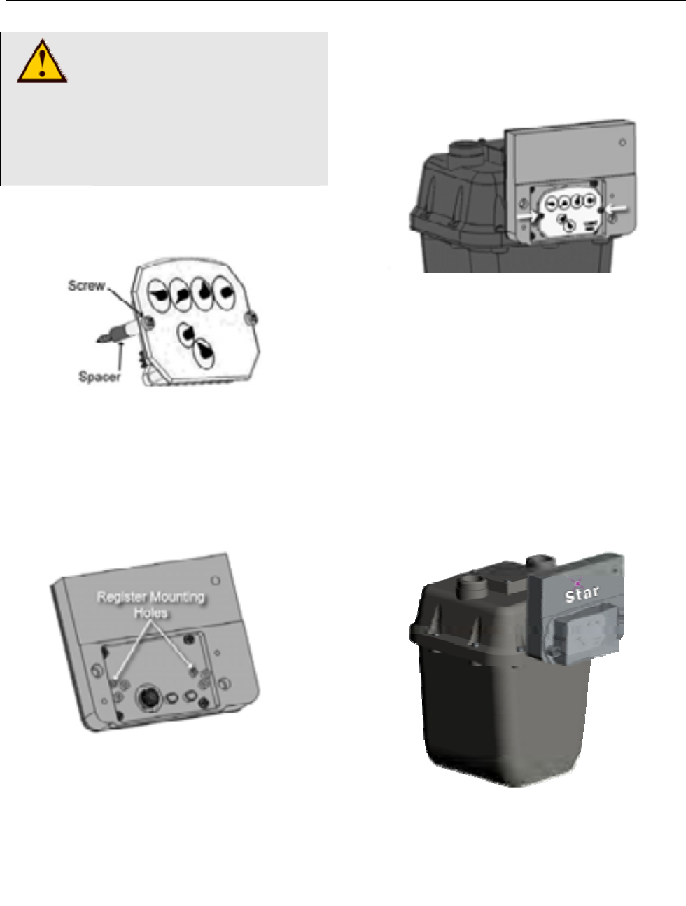
MTU Instruction
for Rockwell/Equimeter/Sensus Gas Meters
CAUTION!
Do not over tighten screws.
Excessive torque may
damage the MTU enclosure.
Power tools are not
recommended for use on
steps 9-12.
Step 8 - On the register, insert the screws
and spacers.
Step 9 - Mount the register to the MTU,
fastening it to the mounting holes shown
below. Hand tighten to a torque not to
exceed 3-5 inch-pounds. Make sure the
index register gear and the MTU coupler
gear are engaged.
Step 10 - After you feel engagement
between the index register gear and the
MTU coupler gear, tighten the register
screws until they are snug.
Step 11 - Place the new cover over the
register so that the top label or arrow is
on top and the vent holes are on the
bottom. Align the cover with the mounting
holes on the MTU, press it into place, and
insert the #10 x 1” screws. Hand tighten
to a torque not to exceed 3-5 inch-
pounds. The gasket should be
compressed slightly.
Step 12 - Replace any anti-tamper,
safety, or security hardware onto the p-
lastic cover as required.
Step 13 – Once Installation is complete,
program the MTU using the STAR
Programmer Software and your MTU
Programmer.
Page 181

MTU Instruction
for Rockwell/Equimeter/Sensus Gas Meters
Intentionally Left Blank
Page 182
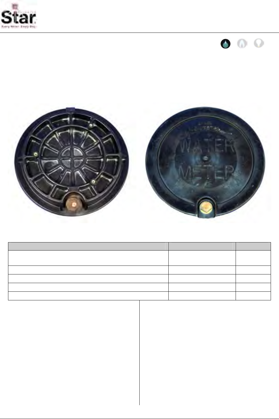
MTU Instruction
for Mid-States 12" Round Pit Lids
Purpose & Scope
This instruction provides a procedure for mounting a STAR Flatpak MTU to a Mid-States
12” Round Pit Lid (Model Number MS-IL1-SN). This procedure does not detail the wiring
of the MTU to the meter that may be encountered inside of the pit. Please refer to
Publication 471-2000, General Installation and Wiring Guidelines in addition to any meter
specific MTU installation and programming instructions.
Parts Required
Item Part Number Quantity
MTU Flatpack - Model 8150 As required for
installed meter 1
Adjustable lid bracket 056-8150H 1
#10-32 x 1-3/4” Phillips pan-head machine screw, stainless 069-103256AS 2
#10-32 x ½” Phillips pan-head machine screw, stainless 069-103216AS 1
Short Spacers 056-8150S 2
Tools Required
To mount the MTU to 12” round Mid-
States pit lids, you will need the following
tools and equipment:
• Safety goggles
• Cordless Drill with variable
speed and adjustable torque
settings
• #2 Phillips power screwdriver
bit
Note on setting the torque range: On a
drill that has about 20 settings (positions)
set the adjustment to #6. Use the lower
speed range of the drill. This should
amount to approximately 8 in-lbs of
torque. Reference the operating
instructions for your particular drill to
more accurately determine what setting to
use to achieve a torque range of
approximately 8 in-lbs.
471-2045 - 4/10/2007
Page 183
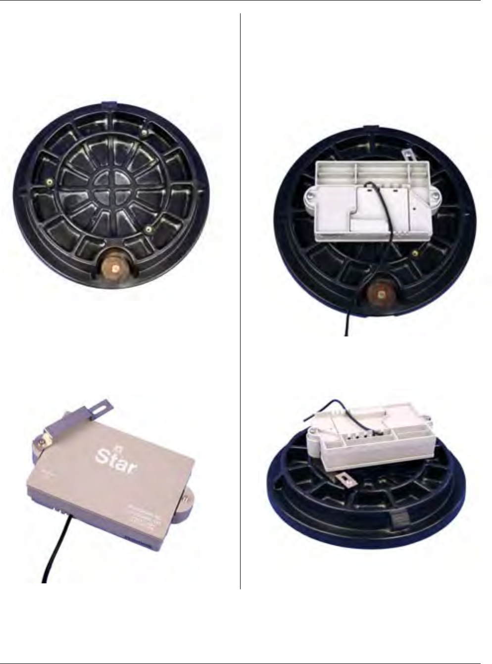
MTU Instruction
for Mid-States 12" Round Pit Lids
Installation Procedure
Step 1 – Place the pit lid top-side down
on a solid surface, positioning the metal
latch nearest to you as shown in the
photo below.
Step 2 – Pre-assemble the MTU, spacers
and bracket as shown below, using the
two #10-32 x 1-3/4” machine screws
through the back of the MTU mounting
tabs and spacers. Thread the bracket
onto the screw at the left side of the MTU
Step 3 – Turn the MTU face down onto
the bottom surface of the pit lid
positioning it as shown below. Align the
slot in the bracket with the mounting post
at the top right and insert the #10-32 x ½”
machine screw. Then tighten all hardware
to approximately 8 in-lbs.
Step 4 – Here’s another view of the
finished assembly. Note the position of
the bracket.
Page 184

MTU Instruction
for Mid-States 12" Round Pit Lids
Step 5 – Wire the MTU to the meter,
bundling the excess wire as necessary so
that it does not interfere with lid locking
mechanism and cannot become pinched
when the lid is placed on the pit.
Step 6 – Installation is now complete.
You can now proceed to program the
MTU using the STAR Field Programmer
Software and your Field Programmer.
CAUTION!
Be sure to follow all General
Guidelines outlined in
Publication 471-2000 along
with the specific wiring
instructions for the meter
being used.
Page 185

MTU Instruction
for Mid-States 12" Round Pit Lids
Intentionally Left Blank
Page 186

MTU Instruction
for Alliance Rectangular Pit Lids
Purpose & Scope
This instruction provides a procedure for temporarily mounting a STAR Flatpak MTU to a
Alliance Rectangular Pit Lid (illustrated below). This procedure does not detail the wiring
of the MTU to the meter that may be encountered inside of the pit. Please refer to
Publication 471-2000, General Installation and Wiring Guidelines in addition to any meter
specific MTU installation and programming instructions.
Parts Required
Item Part Number Quantity
MTU Flatpack - Model 8150 As required for
installed meter 1
Long Plastic Zip Ties Source locally 2
Electric Drill Source locally 1
¼” Drill Bit Source locally 1
Tools Required
To mount the MTU to the Alliance
rectangular pit lids, you will need the
following tools and equipment:
• Safety goggles
• Long plastic zip ties
• 1/4” standard drill bit
• Cordless Drill with variable speed
and adjustable torque settings
Installation Procedure
Step 1 – Drill two holes through ribs on
the bottom of the pit lid as shown below.
Each hole should be approximately ½
inch from the top of the rib
471-2046 - 5/21/2007
Page 187
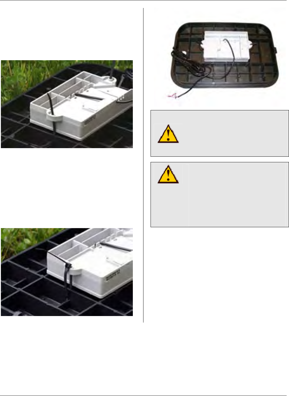
MTU Instruction
for Alliance Rectangular Pit Lids
Step 2 – Position the MTU with the label
side face down against the underside of
the pit lid and thread plastic zip ties
through each of the drilled holes and
through the holes of the MTU mounting
tabs.
Step 3 – Gently pull through the zip ties
so that the MTU is secured to the pit lid.
Do not over tighten the zip ties.
Excessive torque may bend the
mounting tabs and break the seal of
the MTU. Tighten only until the MTU
contacts the lower surface of the pit lid.
Trim the excess length from the zip tie
ends.
CAUTION!
Do not over tighten the zip ties
when mounting the MTU.
Excessive torque can bend
the MTU mounting tabs.
CAUTION!
Be sure to follow all General
Guidelines outlined in
Publication 471-2000 along
with the specific wiring
instructions for the meter
being used.
Step 4 – Wire the MTU to the meter,
forming wires as necessary so that they
do not interfere with lid locking
mechanism and cannot become pinched.
Step 5 – Installation is now complete.
You can now proceed to program the
MTU using the STAR Field Programmer
Software and your Field Programmer.
Page 188
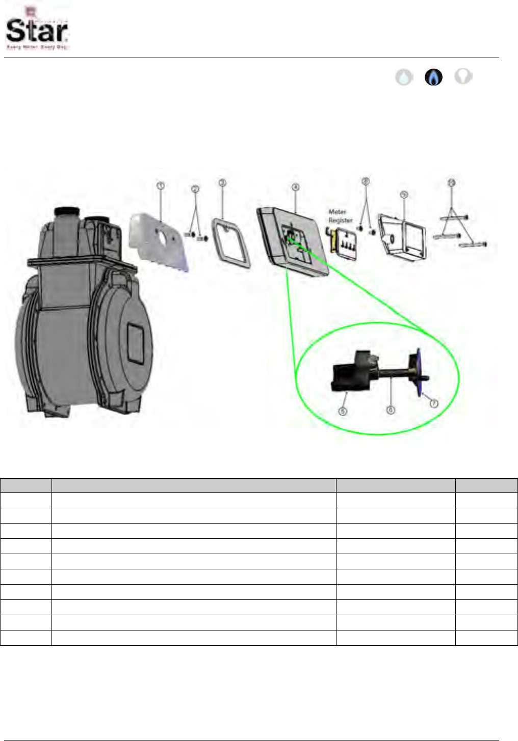
MTU Instruction
for Actaris/Sprague/Schlumberger Gas Meters
Purpose & Scope
This instruction provides a procedure for installing a STAR direct-mount MTU on the
following Actaris/Sprague/Schlumberger residential gas meters: 1A, 175, and 240 (Flat-
face). Please also refer to Publication 471-2000, General Installation and Wiring
Guidelines for general information covering the wiring and mounting of STAR MTUs.
Parts Required
Ref. # Item Part Number Quantity
1 Adaptor 056-12705A 1
2 10-24 x .75” Phillips pan head machine screw, zinc 069-102424A 2
3 Gasket 066-11583 1
4 MTU, Sprague Direct Mount per project 1
5 Tall Magnet Coupler 056-12705B 1
6 Coupler Shaft 056-5155D 1
7 Register Coupler 056-11583D 1
8 #10 x 3/8” combo head thread form screw, Type A, zinc 069-100012C3A 2
9 Clear Register Cover 056-12705C 1
10 10-24 x 2” slotted fillister head machine screw, zinc 069-102464HA 3
471-2047 - 7/18/2007
Page 189
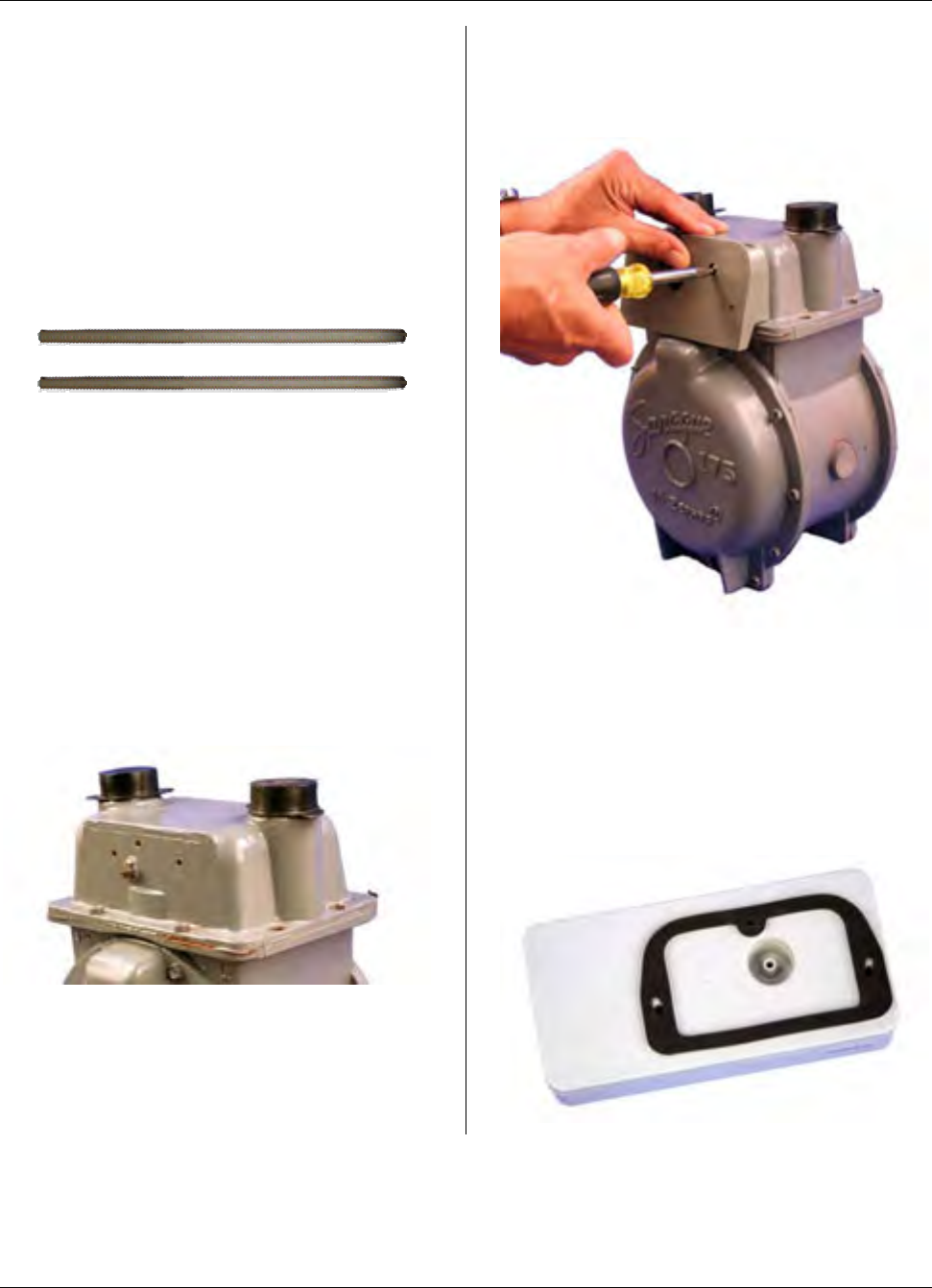
MTU Instruction
for Actaris/Sprague/Schlumberger Gas Meters
Tools Required
To mount the MTU to these meters, you
will need the following tools and
equipment:
• Safety glasses
• #2 Phillips screwdriver
• ¼” Slotted screwdriver
• 2 alignment studs – Hexagram
part number xxx-yyyy
Installation Procedure
Before installing the MTU, all anti-tamper,
safety, and security hardware must be
removed from the clear register cover.
Step 1 - Remove the existing clear
register cover by removing the screws
that hold it. Discard the screws and the
cover.
Step 2 - Remove the register by
removing the two screws that hold it. Set
the register aside and discard the screws.
Step 3 – Mount the adaptor to the meter
head using the two #10-24 x .75”
provided. Tighten these screws to a
torque not to exceed 15 -18 inch-pounds.
Step 4– Remove the paper backing from
the gasket provided to expose the
pressure sensitive adhesive. Place the
gasket on the back of the MTU with the
adhesive surface facing the MTU so that
it aligns over the three mounting screws
and the raised gasket surface of the
MTU.
Page 190
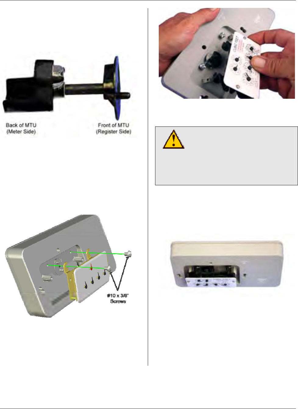
MTU Instruction
for Actaris/Sprague/Schlumberger Gas Meters
Step 5 – Next, assemble the couplers
and shaft to the MTU. Place the flat,
disc-shaped coupler on the shaft and
insert the shaft through the front (register)
side of the MTU.
Then snap the magnet holder on the shaft
from the back of the MTU. Ensure that
both couplers are firmly attached to the
shaft.
Step 6 – Now, mount the register onto
the MTU (see illustration below) fastening
the register to the MTU with the #10 x
3/8” screws provided.
Start the two screws into the mounting
holes, and then slide the register beneath
the screws, making sure that the wiggler
on the register is aligned with the MTU
coupler.
Tighten both screws to a torque not to
exceed 3-5 inch-pounds.
CAUTION!
Do not over tighten screws.
Excessive torque may
damage the MTU enclosure.
Use of power tools is not
recommended.
Step 7 – Check that the register is
properly engaged by rotating the coupler
on the back of the MTU and observing
the register dials.
Page 191

MTU Instruction
for Actaris/Sprague/Schlumberger Gas Meters
Step 8 – Next, thread alignment studs
into the threaded mounting holes on the
left and right side of the adaptor, as
shown below.
Step 9 – Next, slide the MTU over the
alignment studs, positioning the coupler
on the MTU to ensure that it engages
correctly with the wiggler on the gas
meter.
Step 10 – Now, slide the clear register
cover over the alignment studs while you
hold the MTU in position with your free
hand.
Step 11 - Next, insert one of the #10-24 x
2” screws through the top-center hole on
the clear register cover. Tighten this
screw just sufficiently to hold the MTU
and register cover to the meter.
Page 192
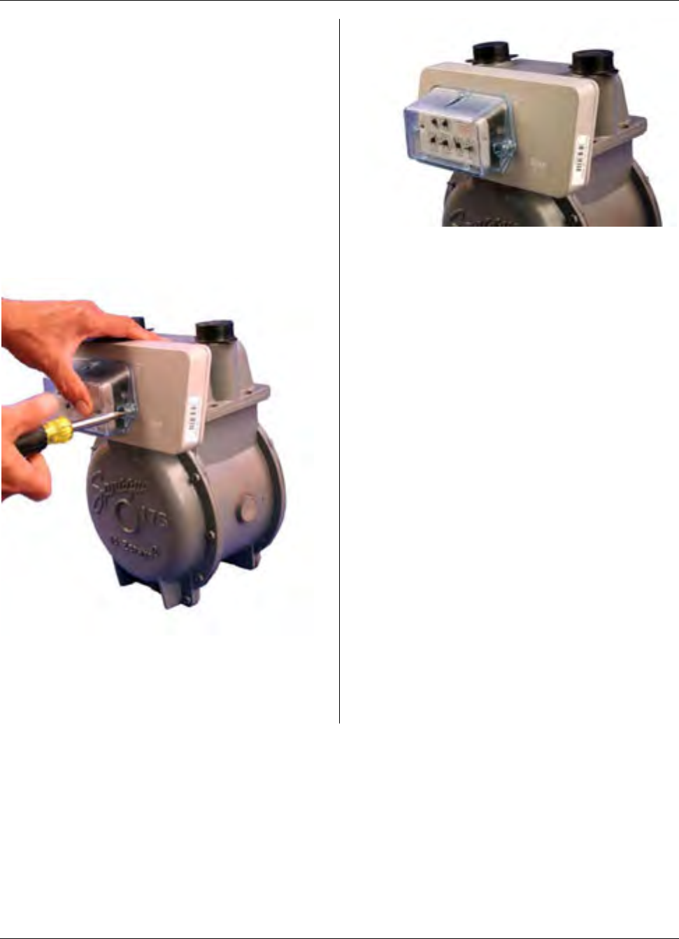
MTU Instruction
for Actaris/Sprague/Schlumberger Gas Meters
Step 12 – Next, remove one of the
alignment studs and replace it with
another one of the #10-24 x 2” screws
provided. Continue in a similar manner,
replacing the other alignment stud with a
#10-24 x 2” screw. Tighten all three
screws to a torque not to exceed 12 -15
inch-pounds. The gasket should be
compressed slightly. Be careful not to
over tighten the screws. Excessive torque
may damage the MTU enclosure.
Because of this, power tools are not
recommended for this procedure.
Step 13 - Replace any anti-tamper,
safety, or security hardware onto the
plastic cover as required.
Step 14 – Once Installation is complete,
program the MTU using your field
programmer and the STAR Programmer
Software.
Page 193

MTU Instruction
for Actaris/Sprague/Schlumberger Gas Meters
Intentionally Left Blank
Page 194

MTU Instruction
for Actaris Dattus Gas Meters
Purpose & Scope
This instruction provides wiring information for use in connecting a STAR MTU to Actaris
Dattus fm2 & fm3 Commercial and Industrial Gas Meters.
Notes:
• The pulse output of the Dattus meter
can be customer configured. For
successful operation with a STAR
MTU, the pulse rate must be
configured so as not to exceed 3
pulses per second at the maximum
flow rate supported by the meter.
471-2051 - 6/9/2008
Page 195

MTU Instruction
for Actaris Dattus Gas Meters
Supplies and Tools Required
See Publication 471-2000, General
Installation and Wiring Guidelines for a
complete list of recommended tools and
supplies for MTU Installation.
Installation Procedure
Step 1 - Select a mounting location for
the MTU that will allow optimum signal
transmission, and install any needed
wiring. Be sure to follow all General
Installation and Wiring Guidelines as
outlined in Publication 471-2000.
Step 2 – Connect the MTU cable to the
Dattus Pulse Ouput cable according to
the table below.
MTU Cable Dattus Pulse Output
Cable
Red Red (Channel 1 +)
Black Green (Channel 1 -)
White Green (Channel 1 -)
Step 3 – Make a final visual check of the
wiring from the MTU to the meter. Verify
that the cable routing is neat, secure and
professional.
Step 4 – Once installation and wiring are
complete, program the MTU using the
STAR Programmer Software and your
MTU Programmer.
Page 196
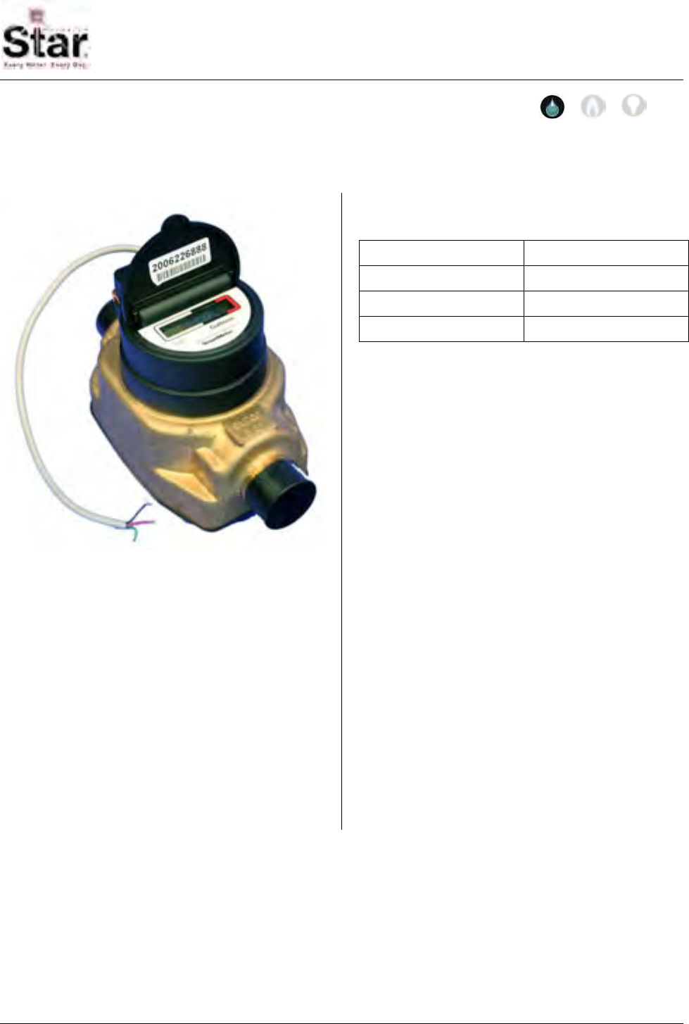
MTU Instruction
for Severn Trent Water Meters
471-2052 - 6/9/2008
Purpose & Scope
This instruction provides wiring information for use in connecting a STAR MTU to Severn
Trent Water Meters.
Supplies and Tools Required
See Publication 471-2000, General
Installation and Wiring Guidelines for a
complete list of recommended tools and
supplies for MTU Installation.
Installation Procedure
Step 1 - Select a mounting location for
the MTU that will allow optimum signal
transmission, and install any needed
wiring. Be sure to follow all General
Installation and Wiring Guidelines as
outlined in Publication 471-2000.
Step 2 – Connect the MTU cable to the
meter cable according to the table below.
MTU Cable Meter Cable
Red Red
Black Black
White Green
Step 3 – Make a final visual check of the
wiring from the MTU to the meter. Verify
that the cable routing is neat, secure and
professional.
Step 4 – Once installation and wiring are
complete, program the MTU using the
STAR Programmer Software and your
MTU Programmer.
Page 197

MTU Instruction
for Severn Trent Water Meters
Intentionally Left Blank
Page 198

MTU Instruction
for Endress & Hauser PROMAG Water Meters
471-2053 - 3/17/2009
Purpose & Scope
This instruction provides wiring information for use in connecting a STAR MTU to Endress
& Hauser PROMAG Water Meters.
Supplies and Tools Required
See Publication 471-2000, General
Installation and Wiring Guidelines for a
complete list of recommended tools and
supplies for MTU Installation.
Notes:
• The pulse output of the PROMAG is
configurable. For successful
operation with a STAR MTU, the pulse
rate must be configured so as not to
exceed 3 pulses per second at the
maximum flow rate supported by the
meter.
Page 199
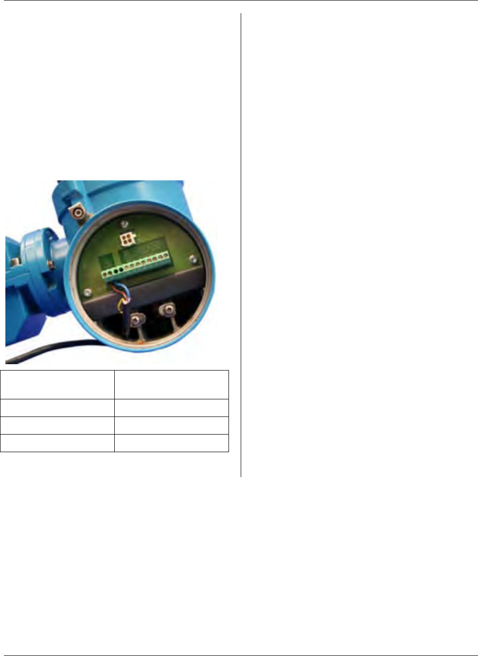
MTU Instruction
for Endress & Hauser PROMAG Water Meters
Installation Procedure
Step 1 - Select a mounting location for
the MTU that will allow optimum signal
transmission, and install any needed
wiring. Be sure to follow all General
Installation and Wiring Guidelines as
outlined in Publication 471-2000.
Step 2 – Connect the MTU cable to the
terminal strip located .under a cover plate
around to the right of the meter display.
(See the photo and wiring table below.)
MTU Cable PROMAG Terminal
Strip
Red Terminal #24 (+)
Black Terminal #25 (-)
White Terminal #25 (-)
Step 3 – Make a final visual check of the
wiring from the MTU to the meter. Verify
that the cable routing is neat, secure and
professional.
Step 4 – Once installation and wiring are
complete, program the MTU using the
STAR Programmer Software and your
MTU Programmer.
Page 200

MTU Instruction
for Actaris Cyble Water Meters
Purpose & Scope
This instruction provides wiring information for use in connecting a STAR MTU to Actaris
Cyble Water Meters.
Supplies and Tools Required
See Publication 471-2000, General
Installation and Wiring Guidelines for a
complete list of recommended tools and
supplies for MTU Installation.
Installation Procedure
Step 1 - Select a mounting location for
the MTU that will allow optimum signal
transmission, and install any needed
wiring. Be sure to follow all General
Installation and Wiring Guidelines as
outlined in Publication 471-2000.
Step 2 – Connect the MTU cable to the
Cyble or Cyble Coder cable as shown in
the tables below.
Cyble Sensor (Pulser)
MTU Cable Cyble Sensor Cable
(Grey Jacket)
Red Brown
Black White
White White
Connect to an “R” type STAR MTU Port.
471-2054 - 6/22/2008
Page 201

MTU Instruction
for Actaris Cyble Water Meters
Cyble Coder
MTU Cable Cyble Coder Cable
(Black Jacket)
Red Red
Black Black
White Green
Connect to a “D” type STAR MTU Port.
Note: The Cyble Coder must be configured for a
6-digit reading
Step 3 – Make a final visual check of the
wiring from the MTU to the meter. Verify
that the cable routing is neat, secure and
professional.
Step 4 – Once installation and wiring are
complete, program the MTU using the
STAR Programmer Software and your
MTU Programmer.
Page 202