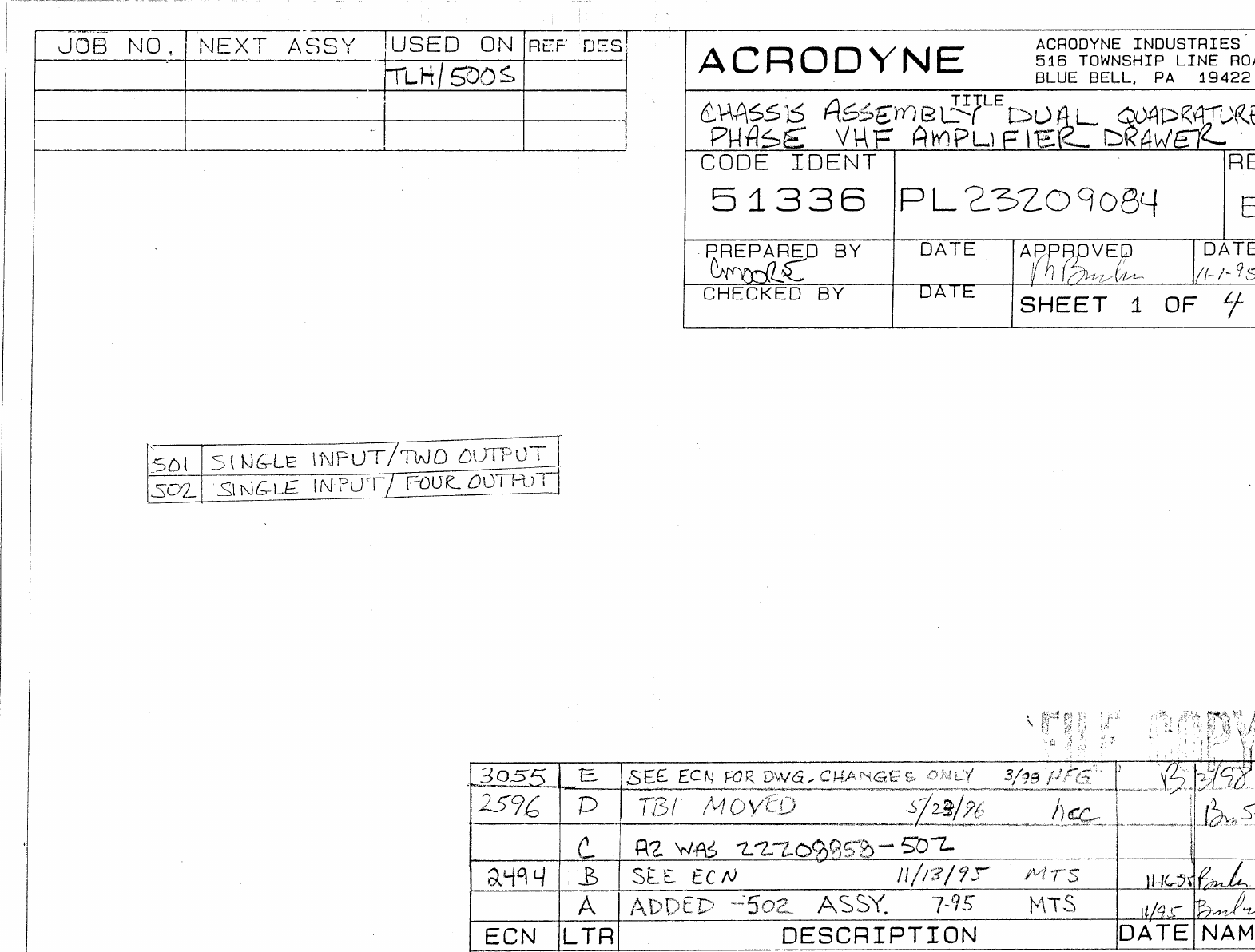
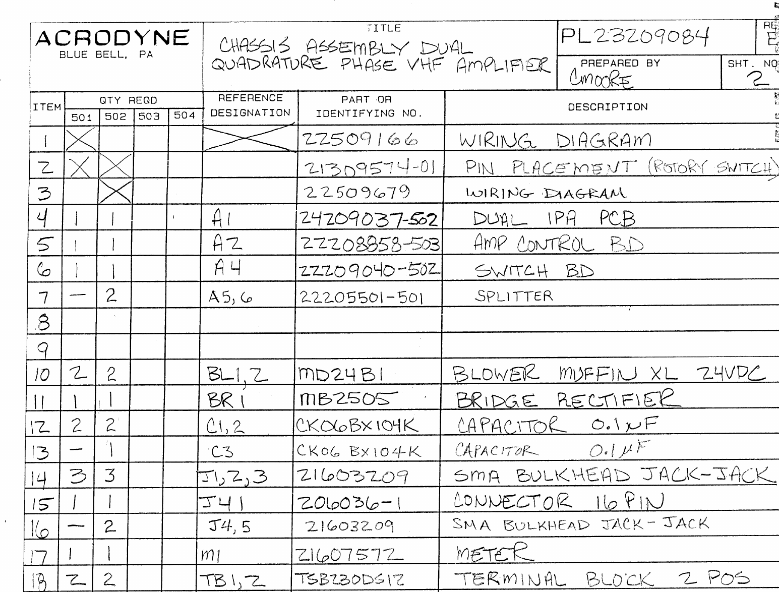
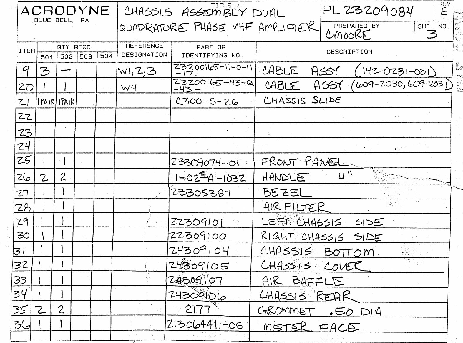
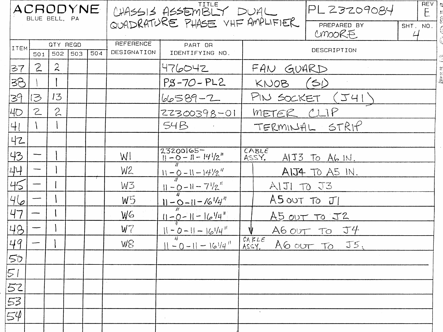
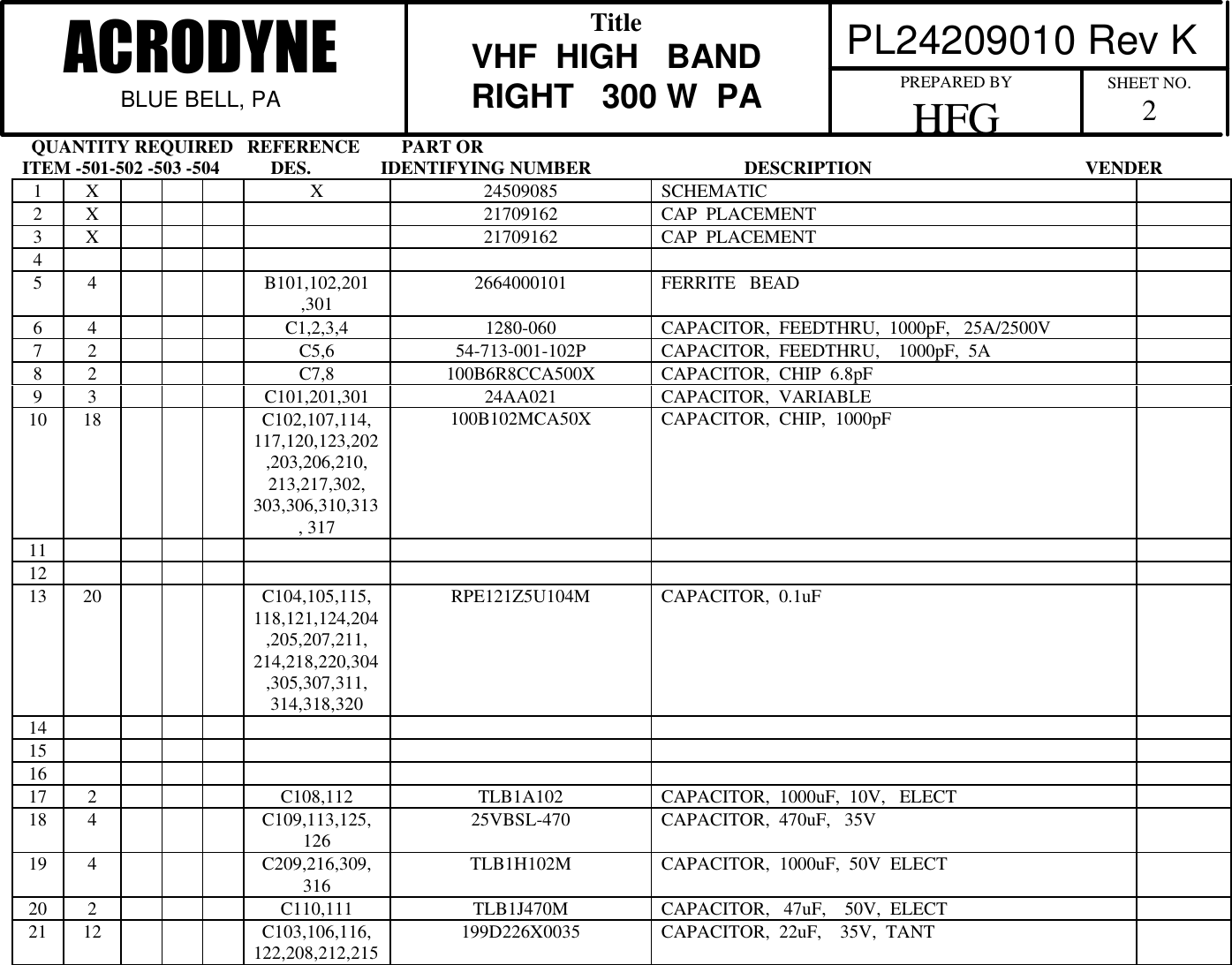
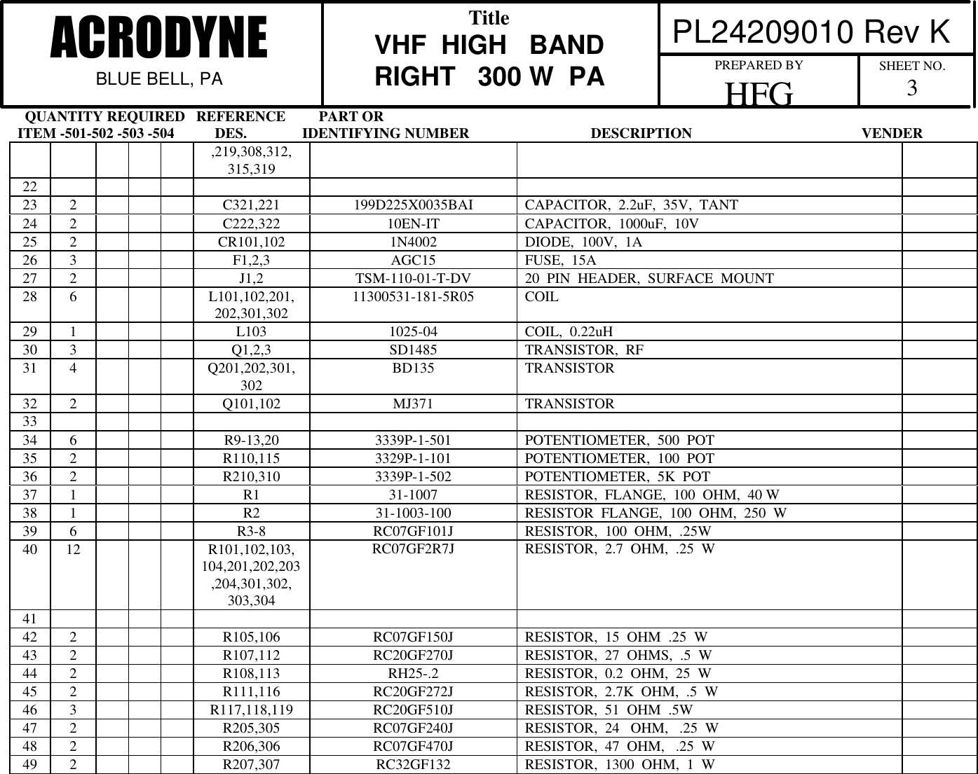
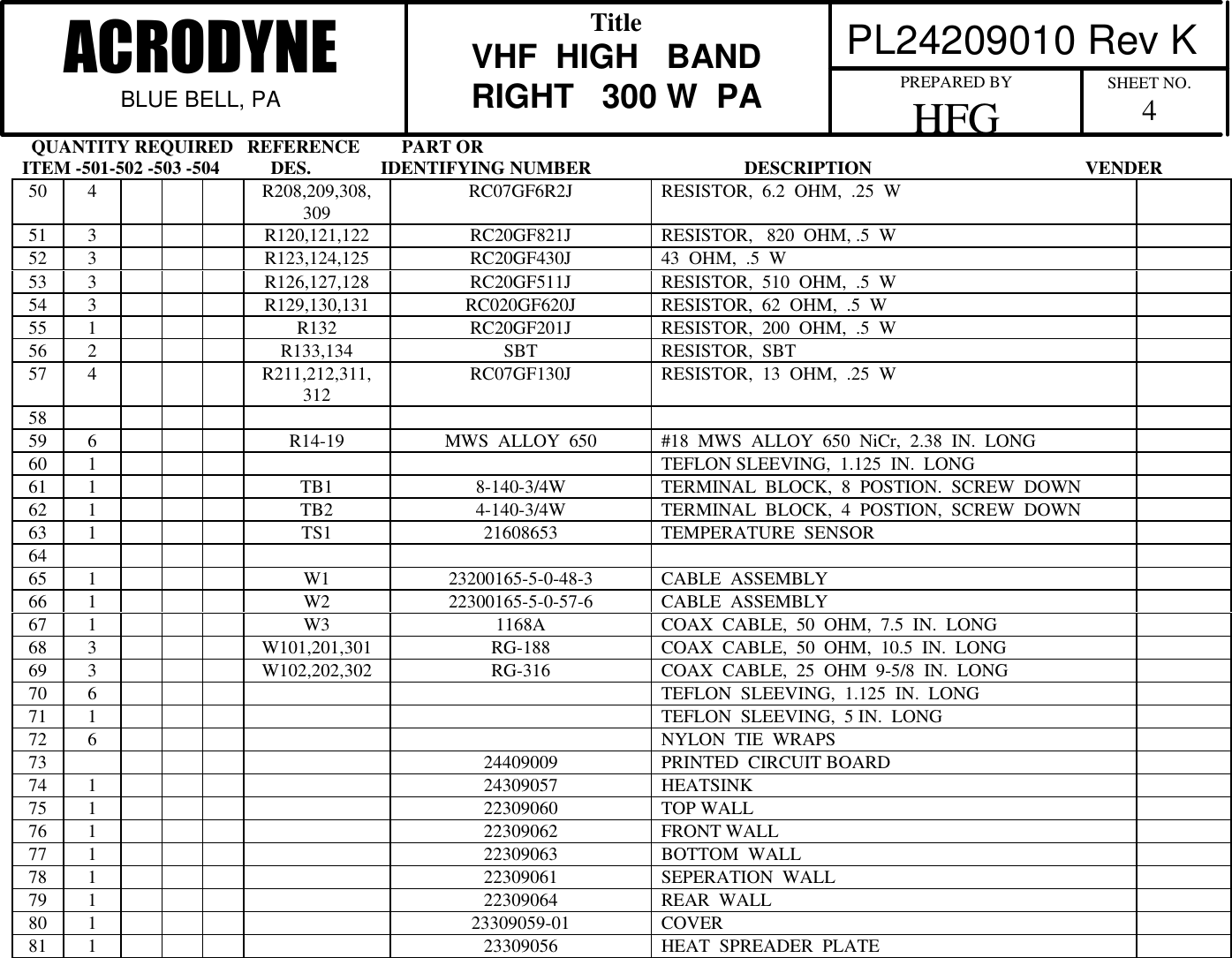
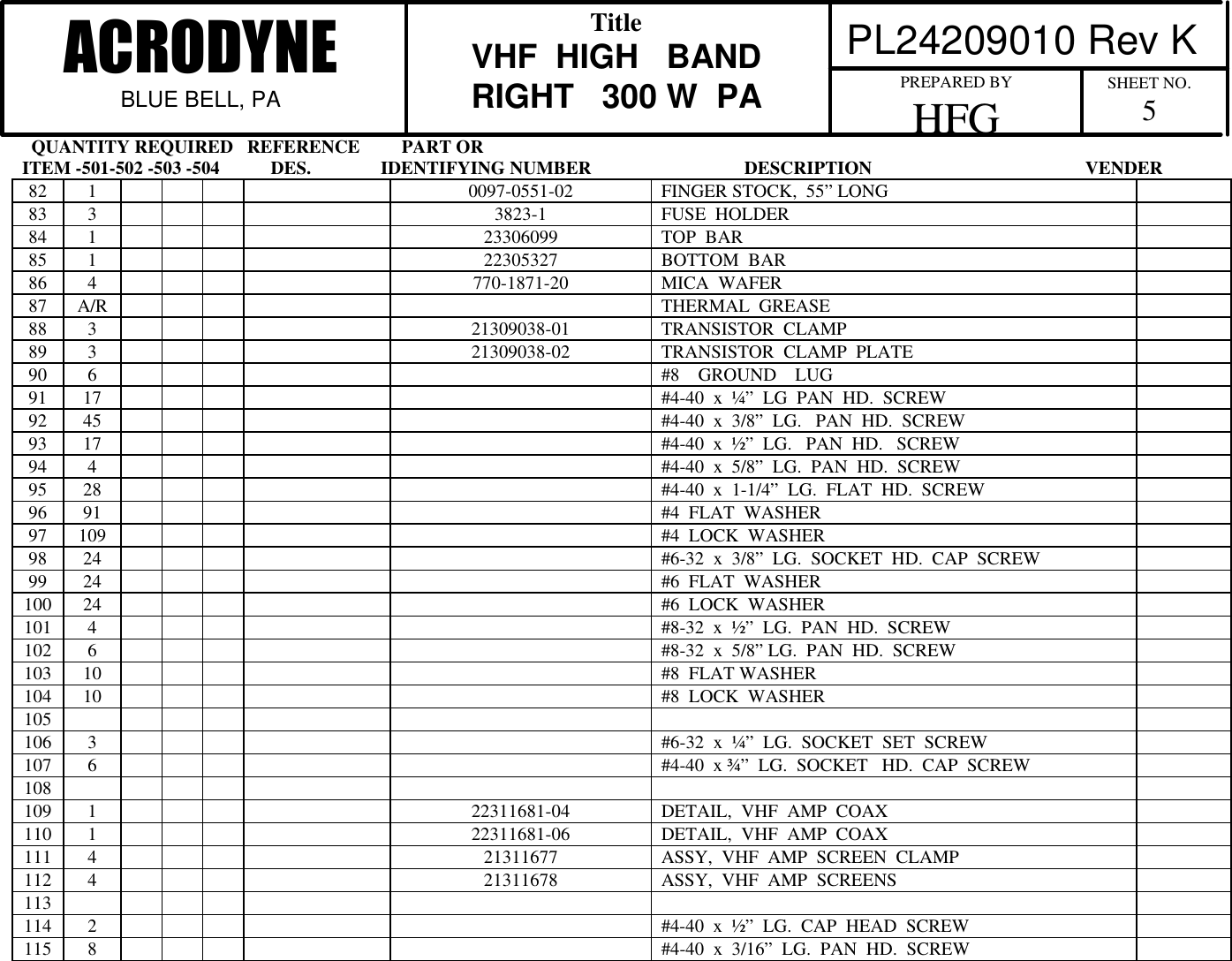
Acrodyne 22802332 Broadcast Television Transmitter User Manual TRH1KE 3
Acrodyne Industries, Inc. Broadcast Television Transmitter TRH1KE 3
Acrodyne >
Contents
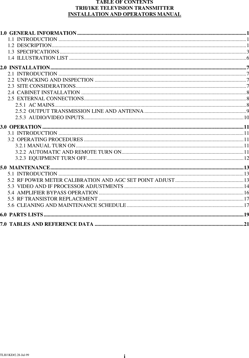
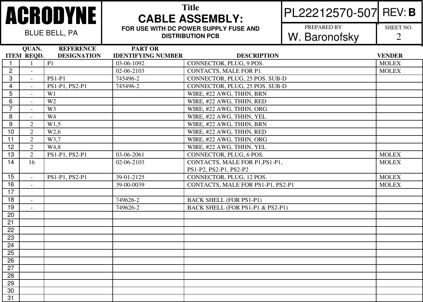
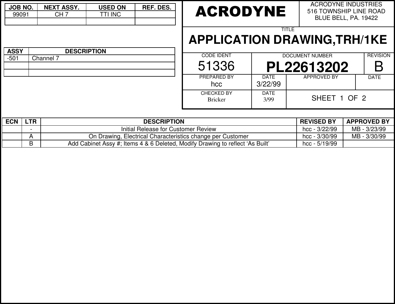
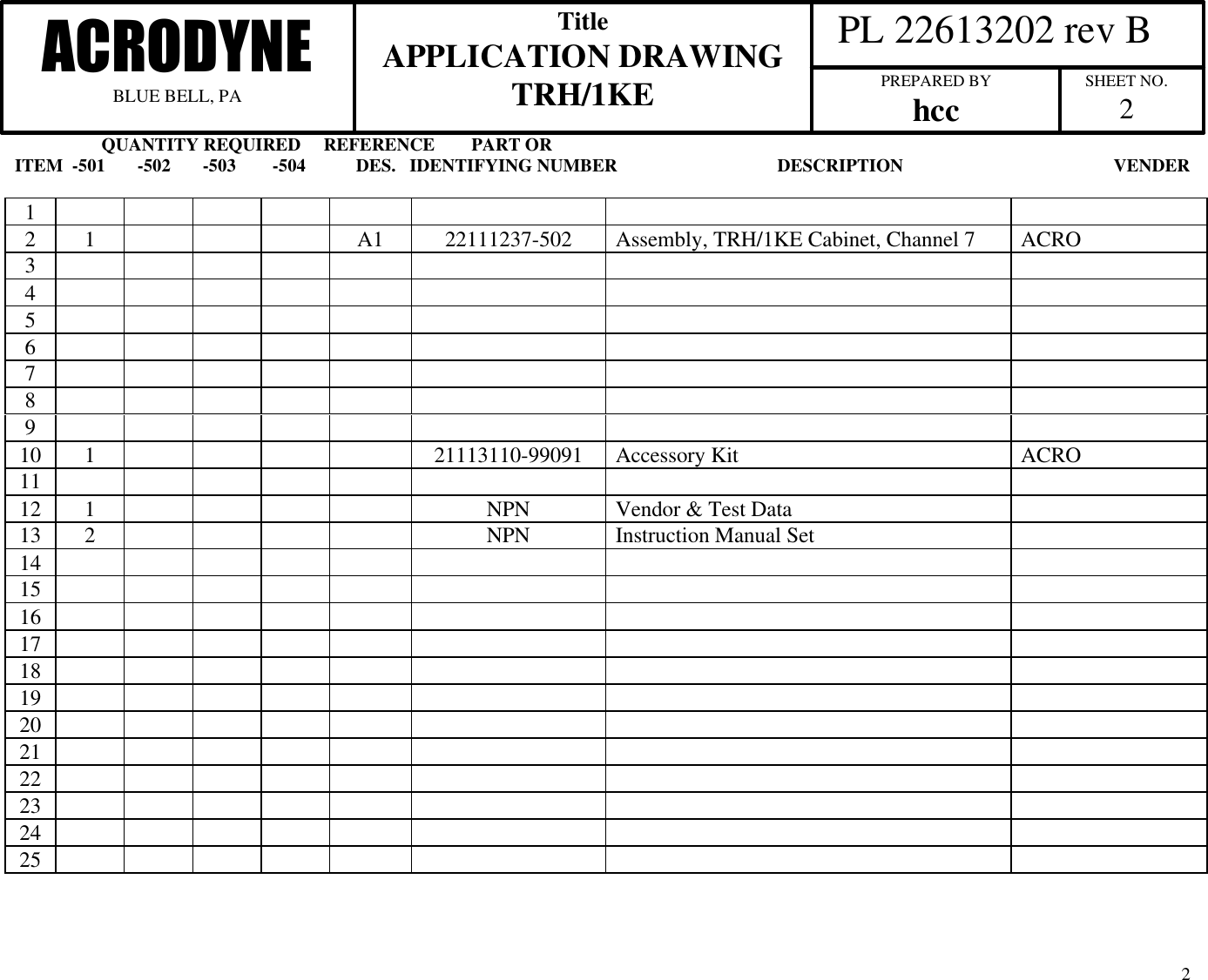
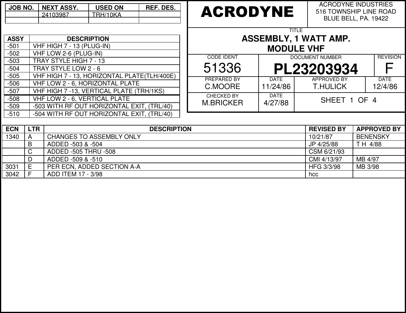
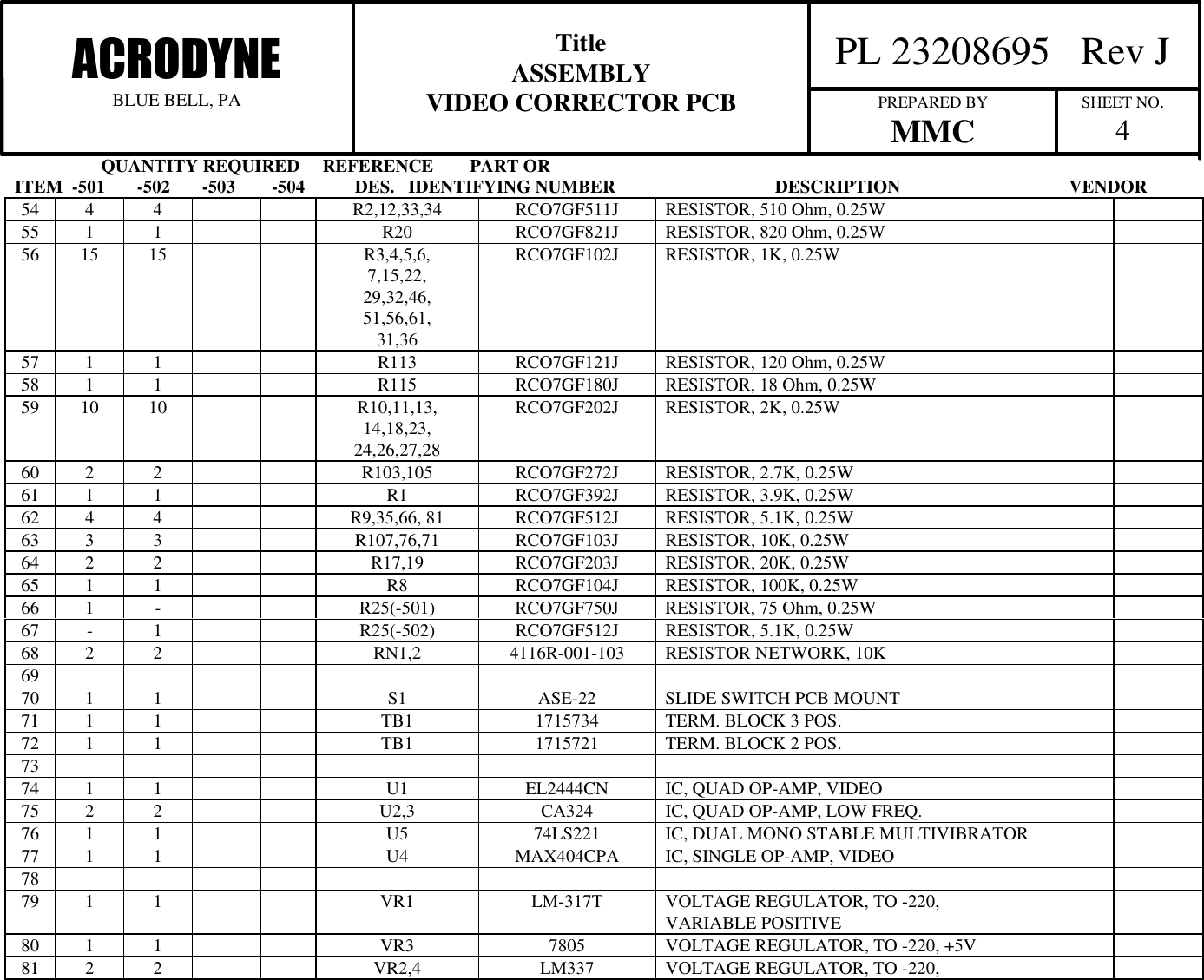
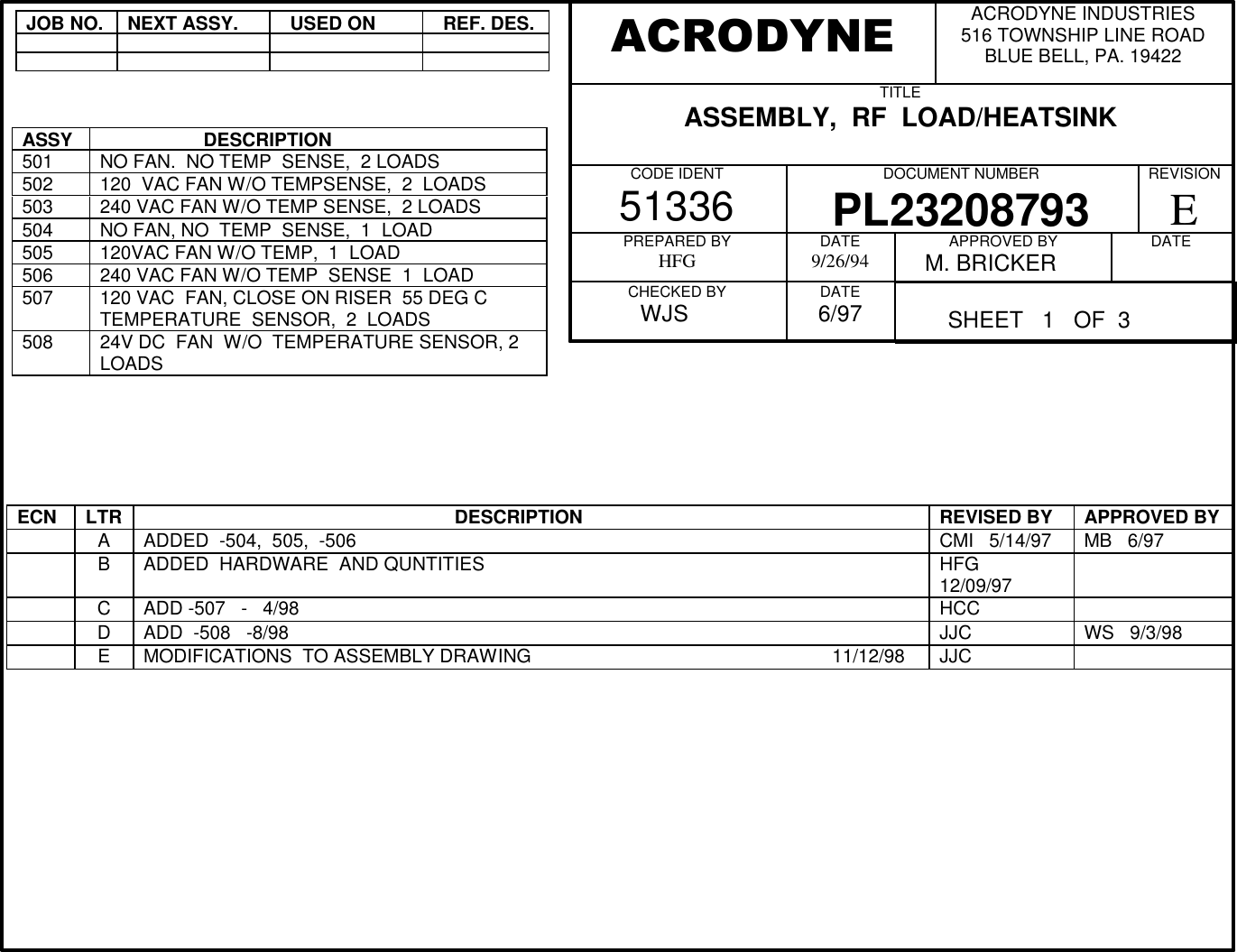
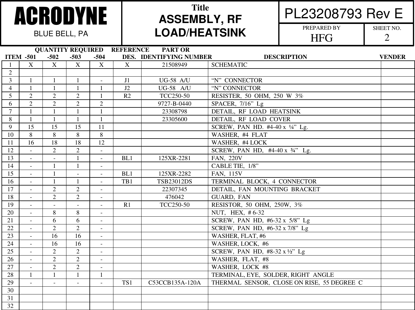
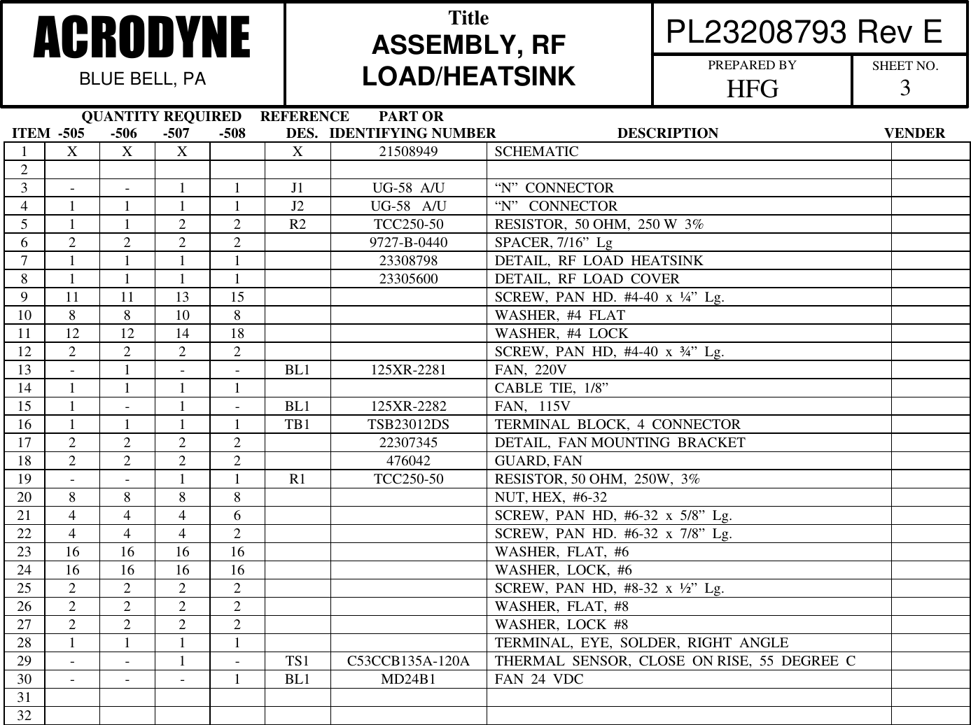
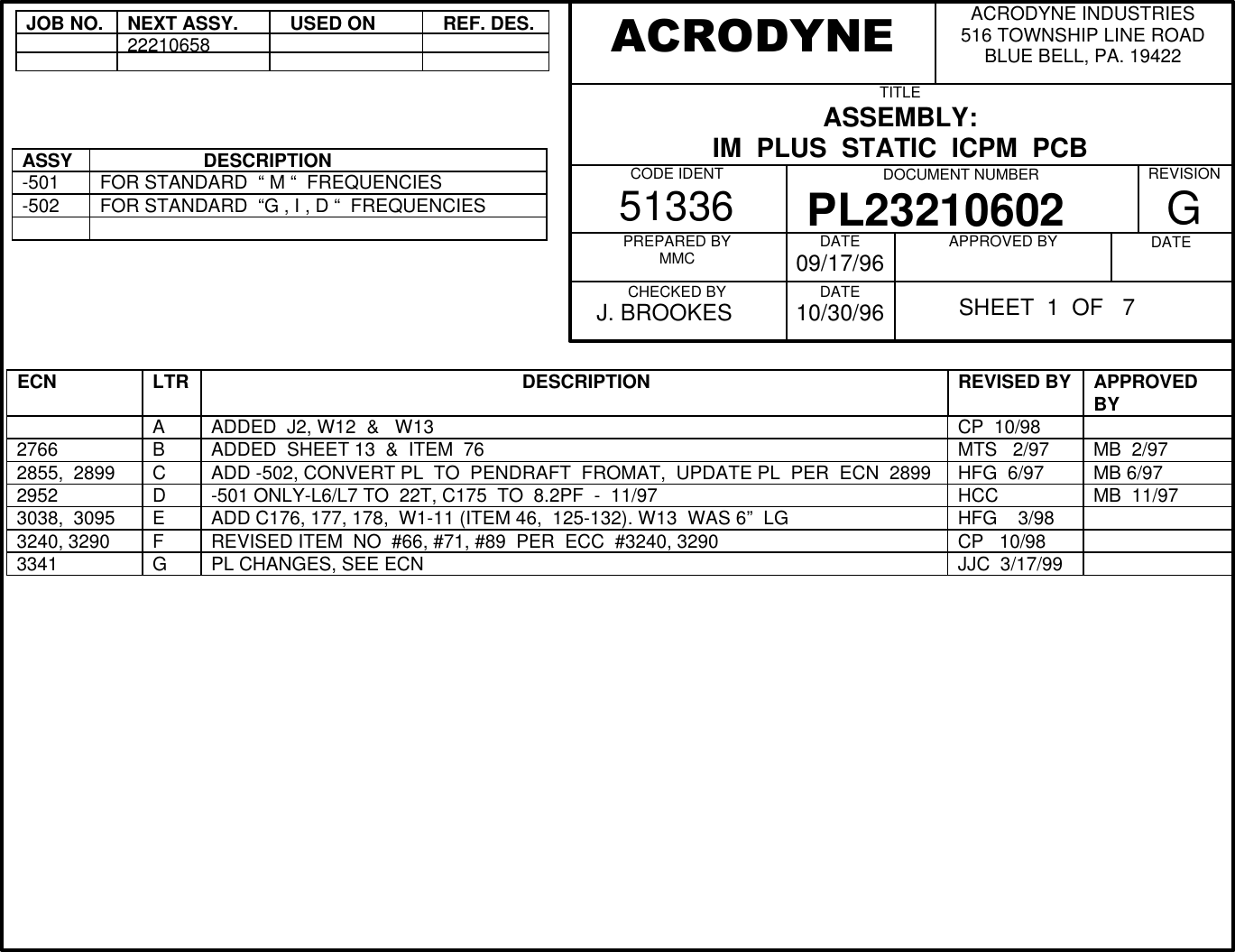
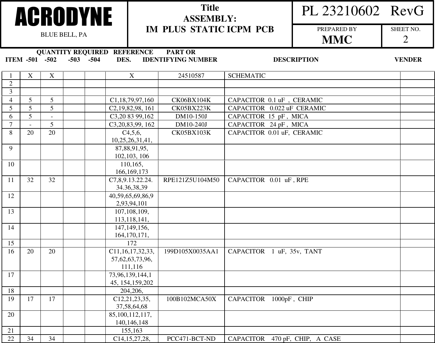
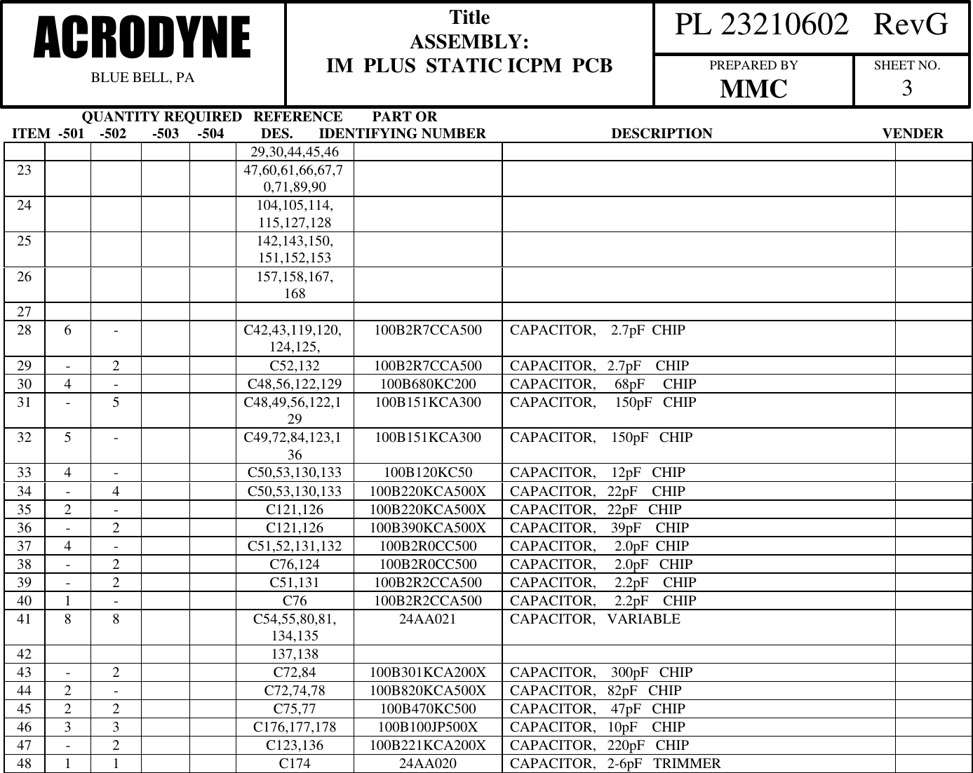
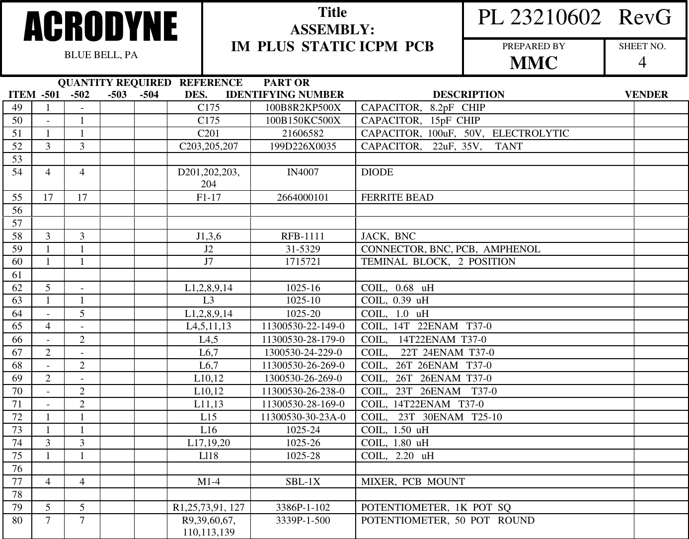
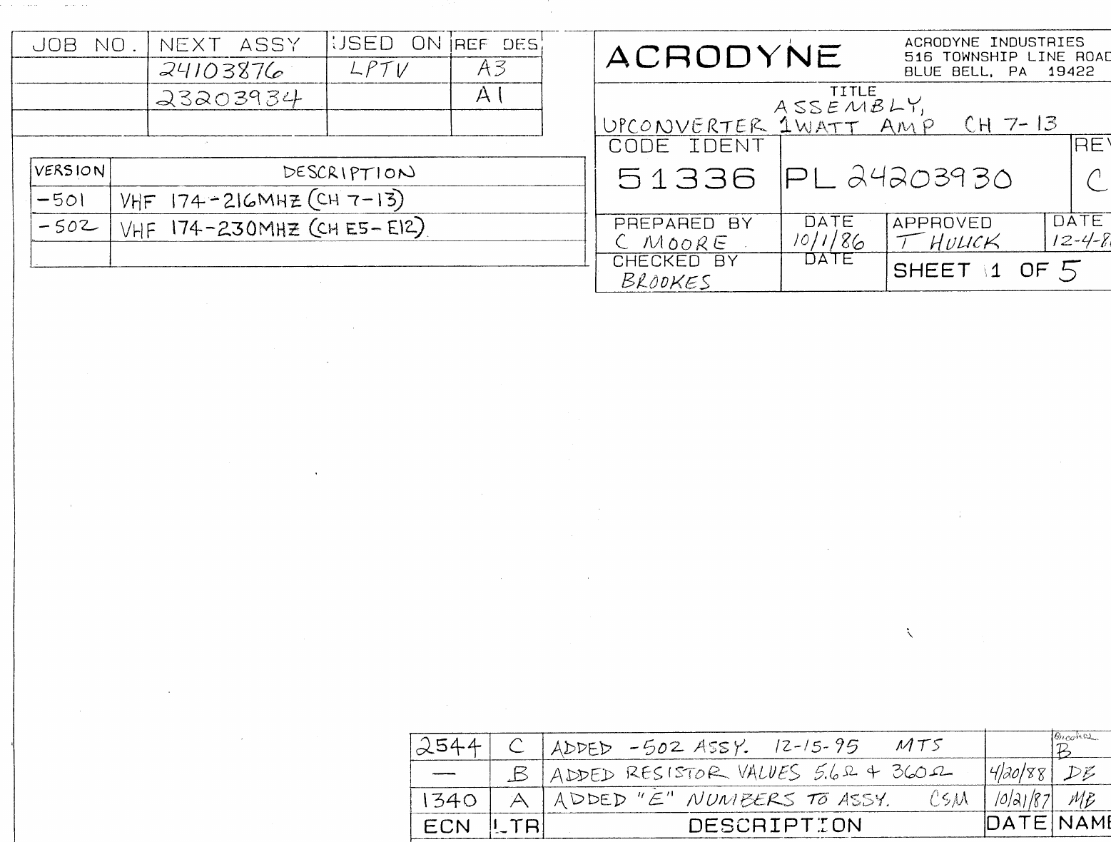
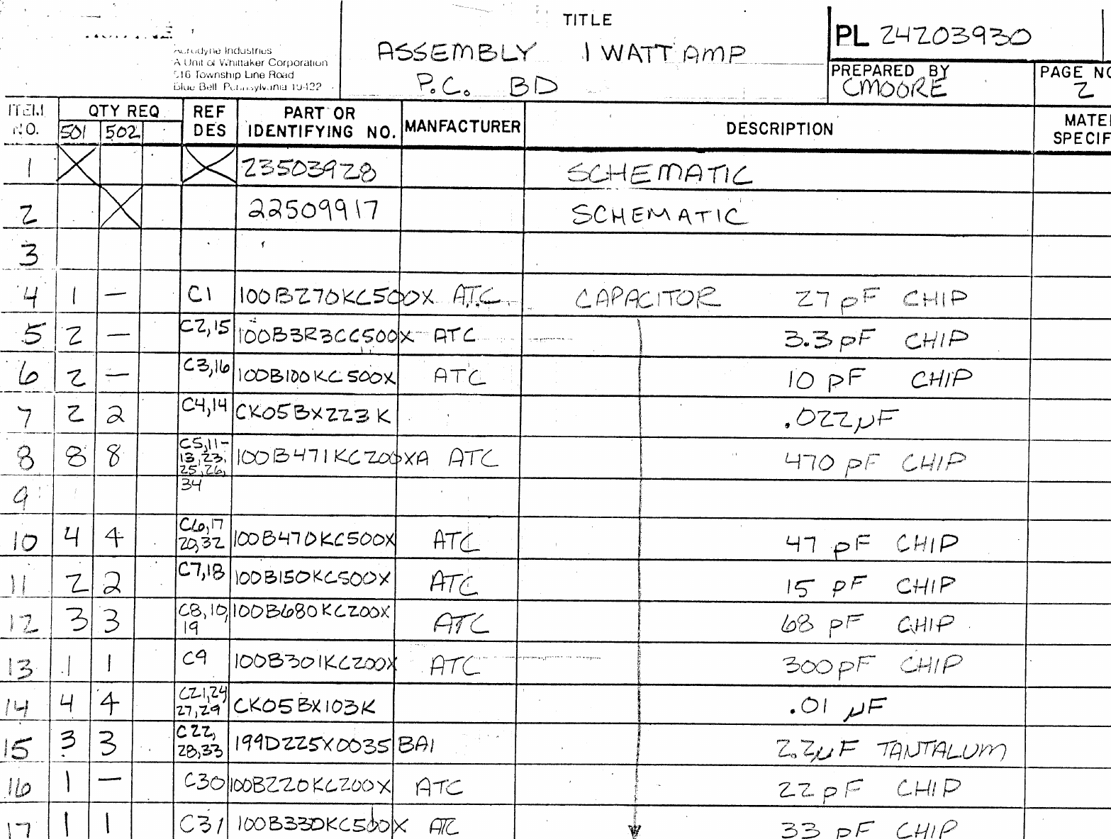
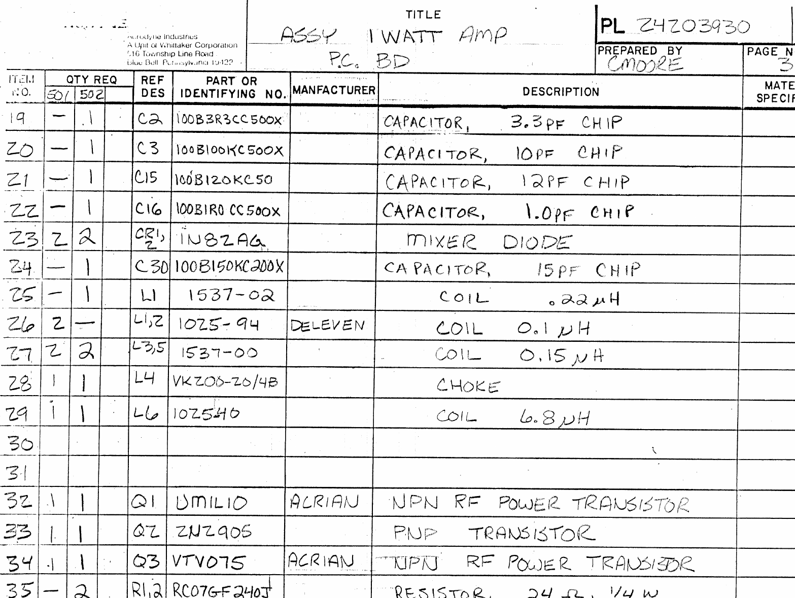
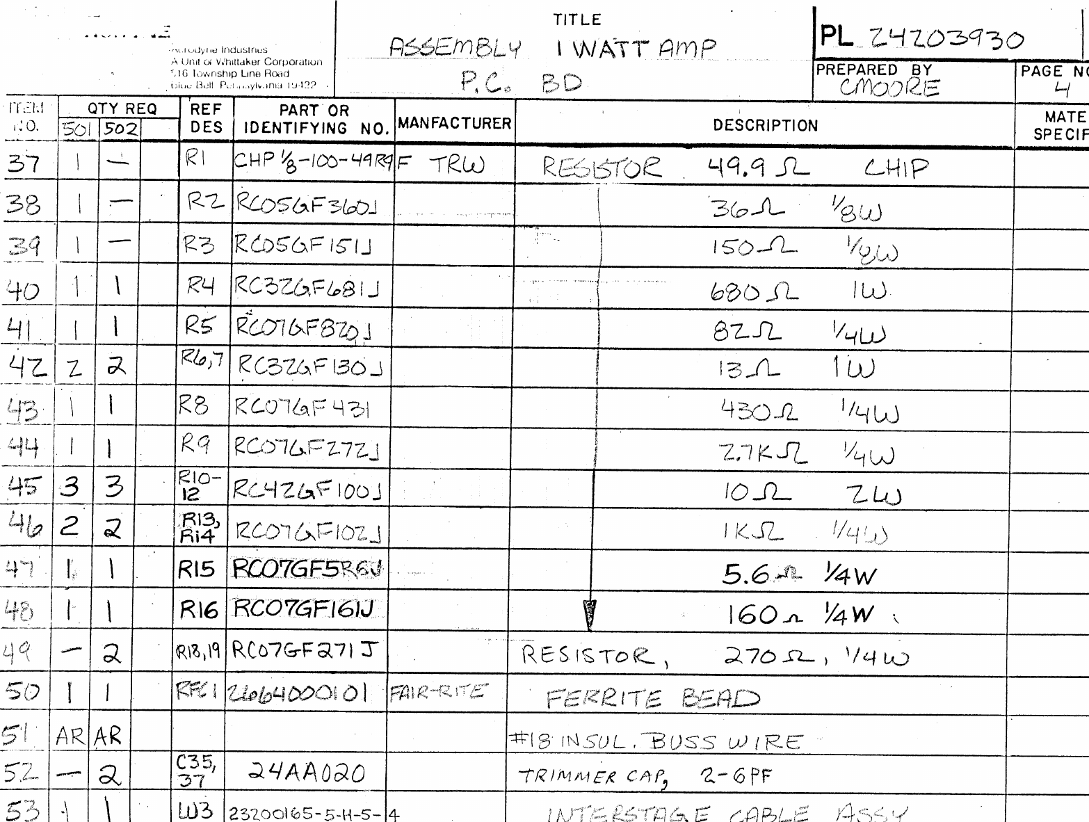
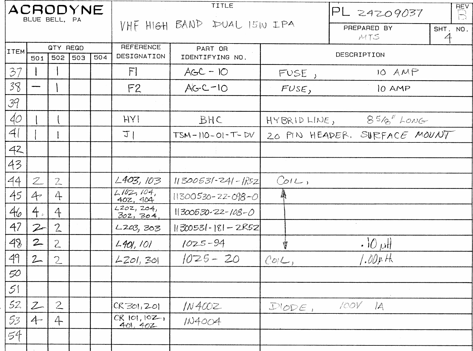
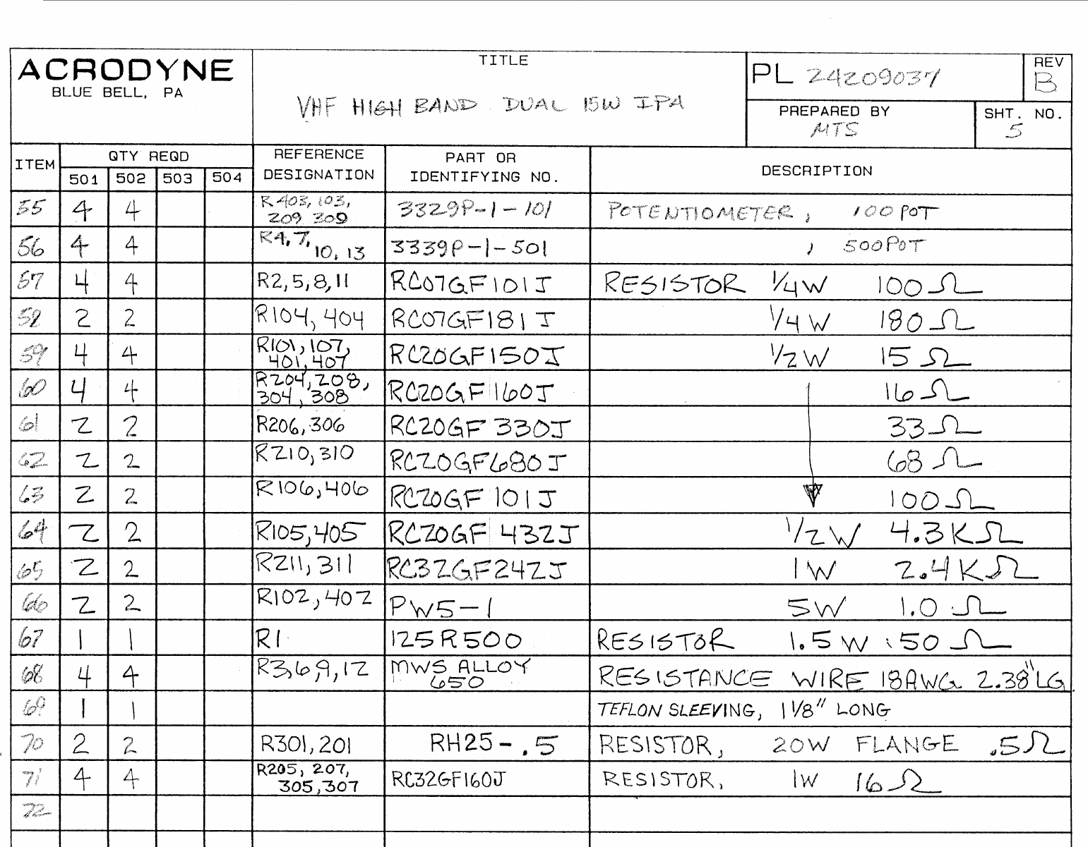
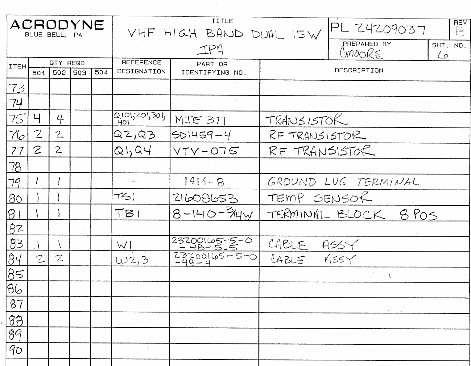
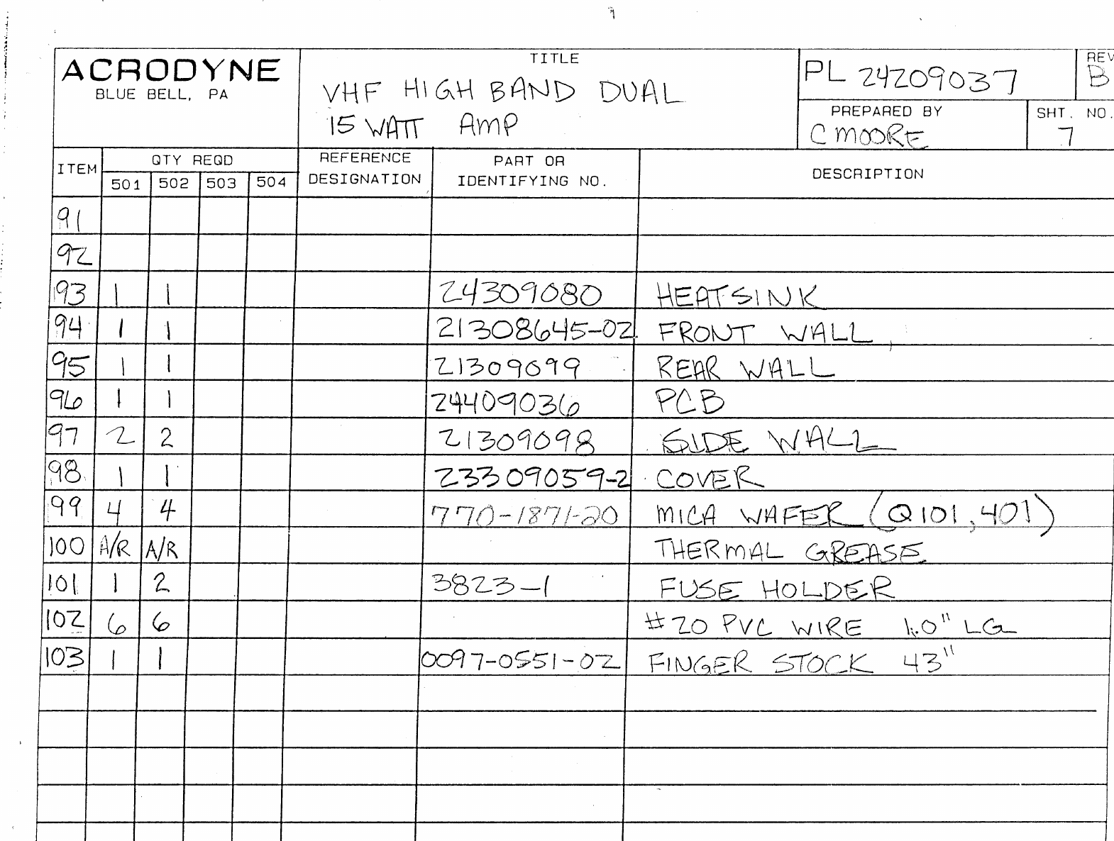
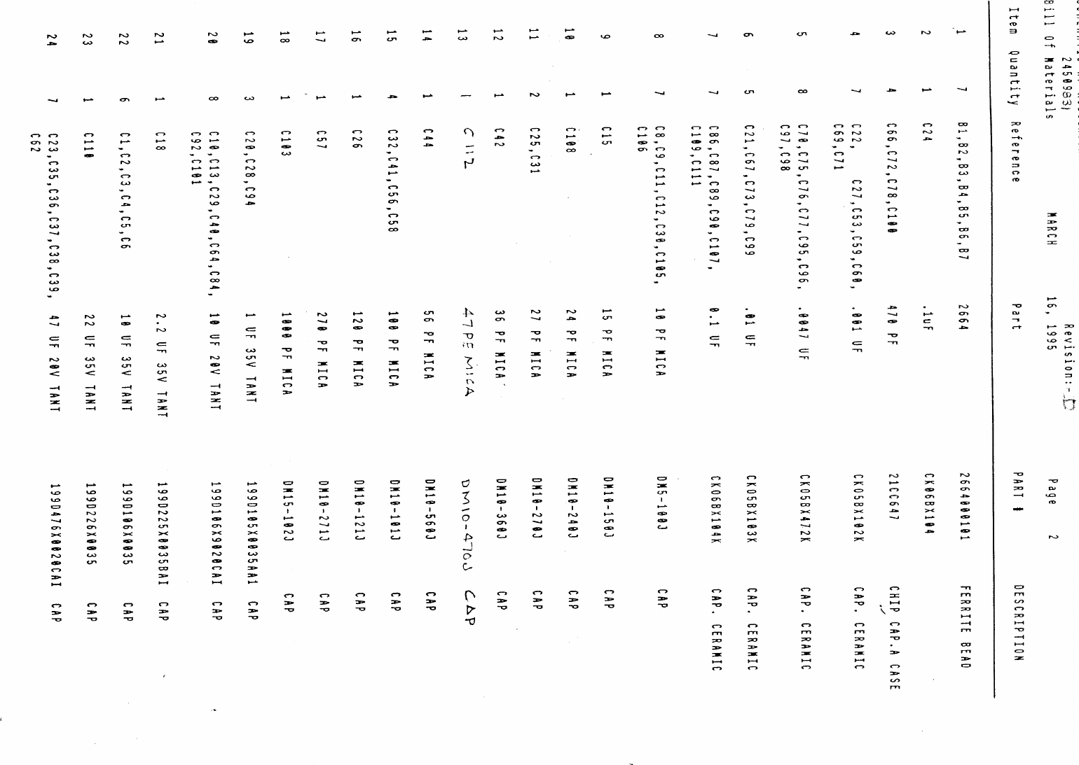
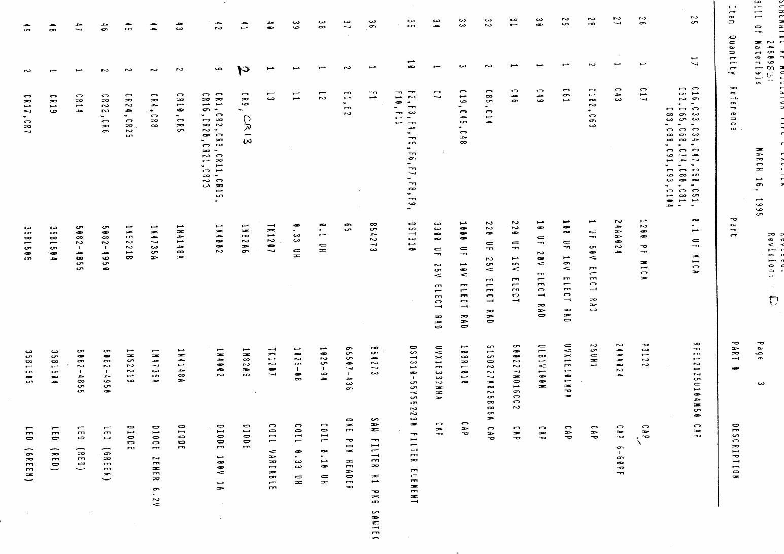
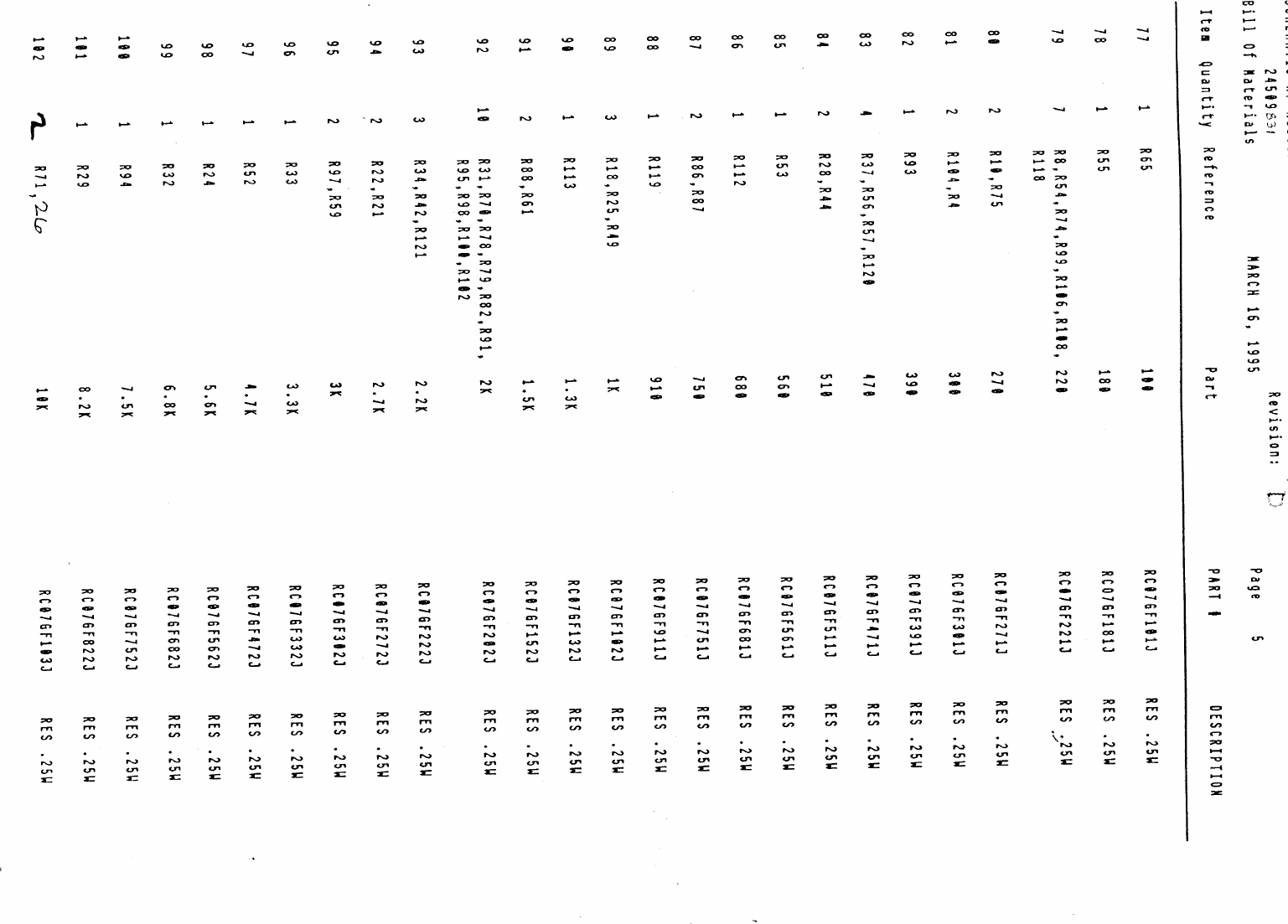
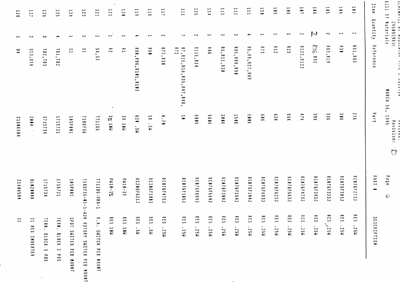
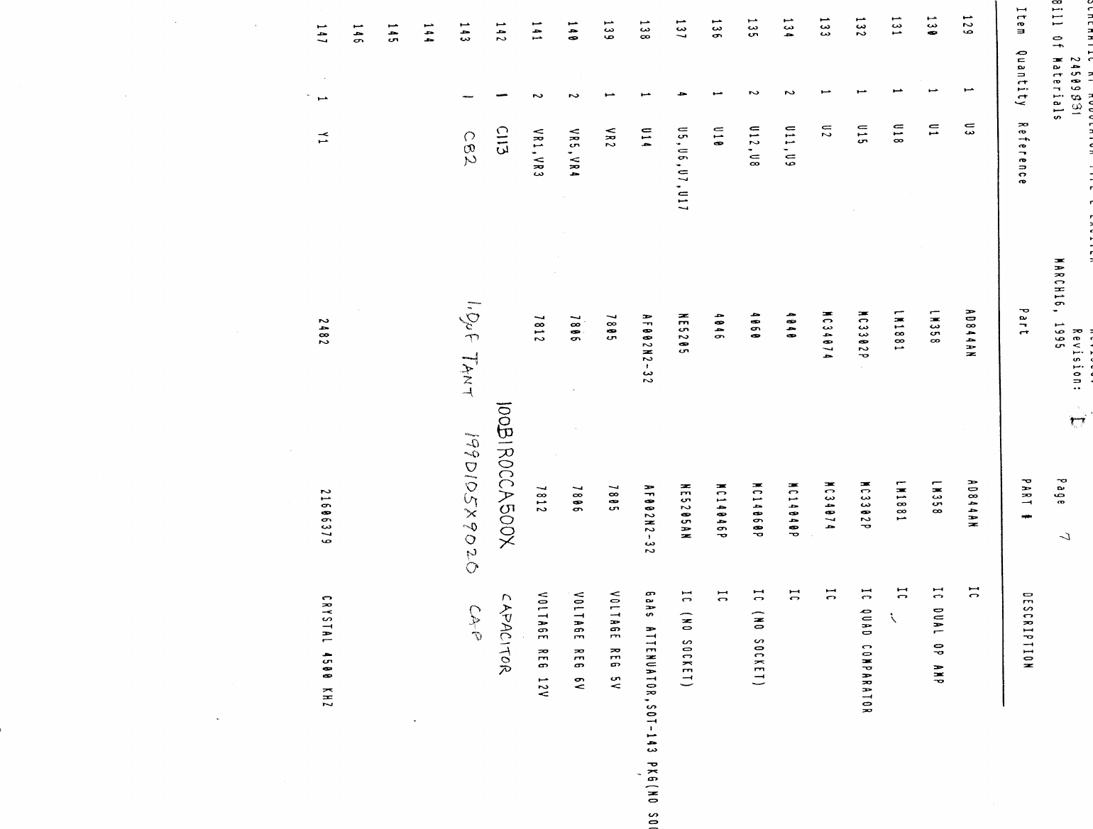
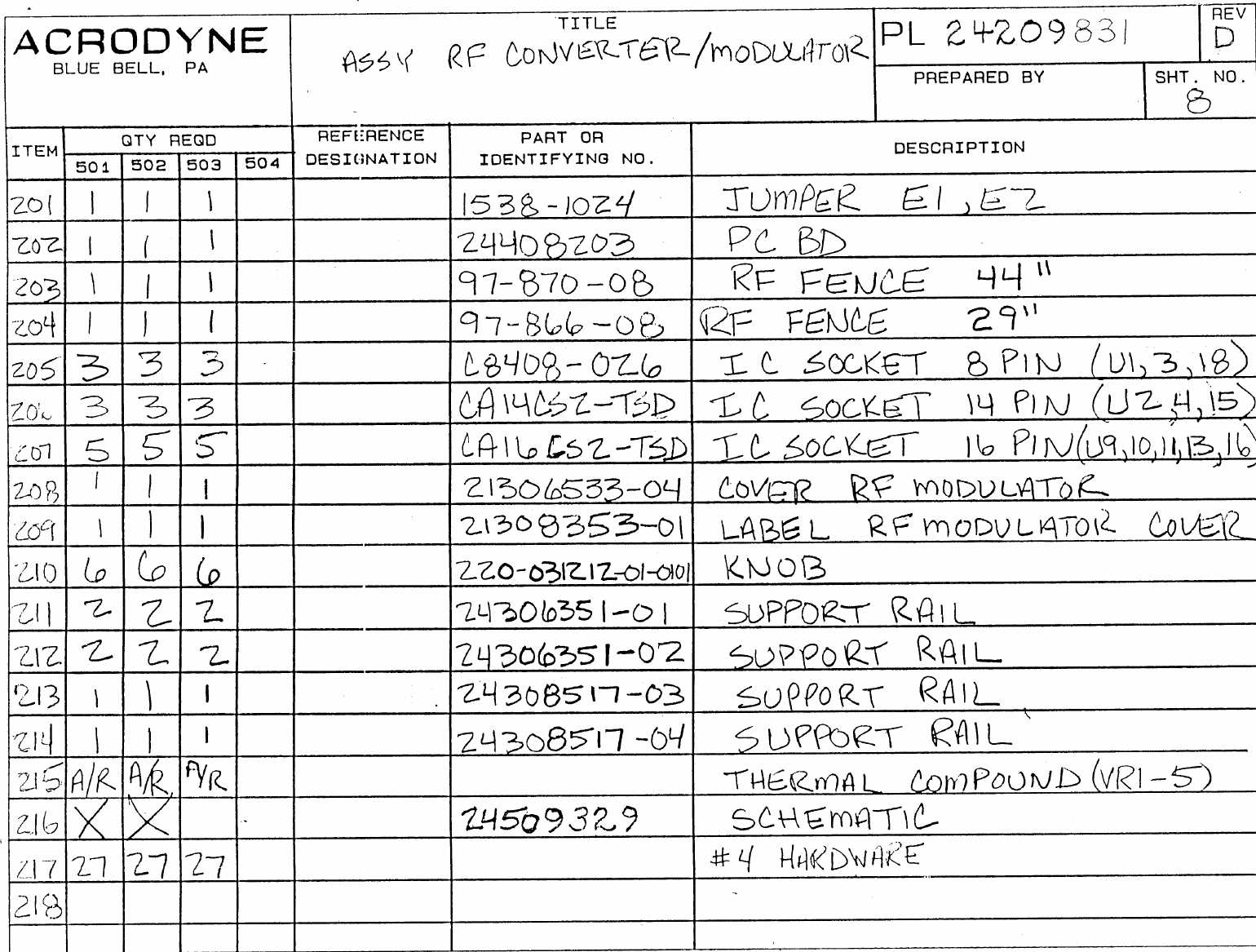
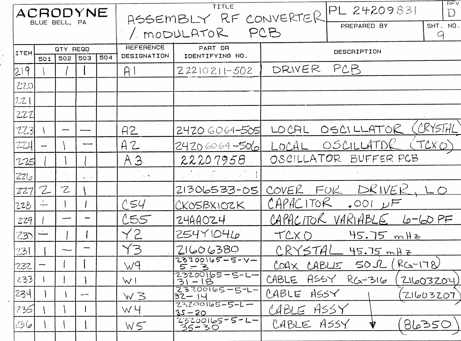
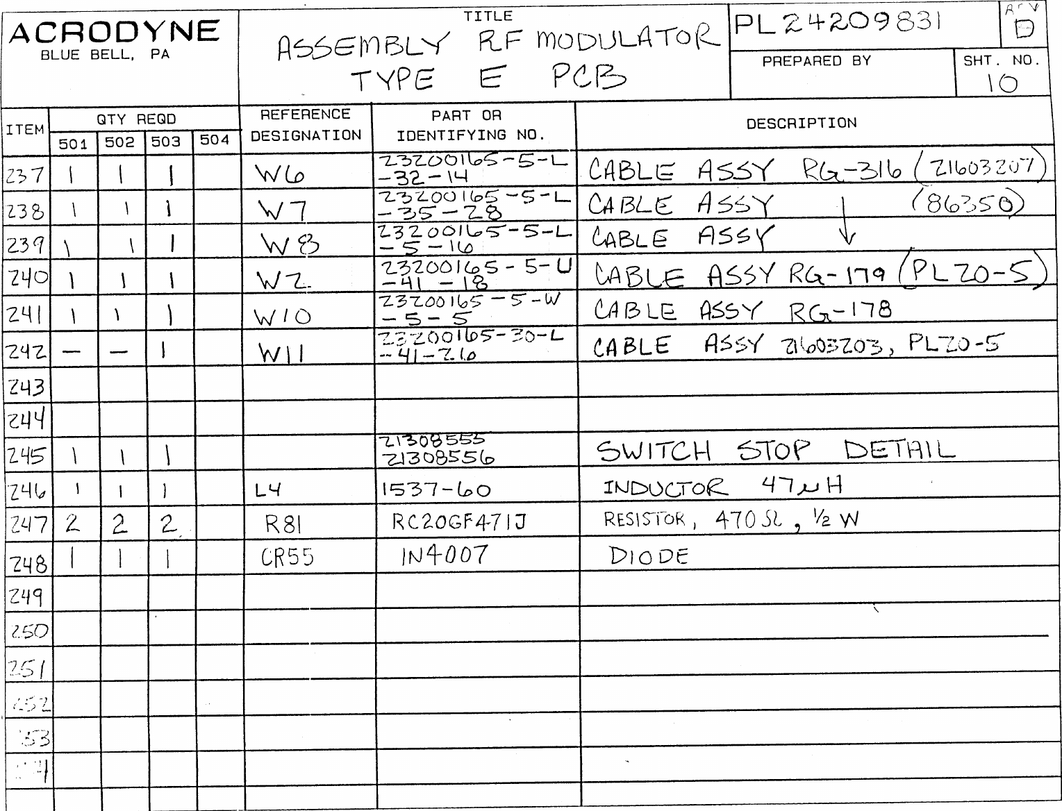
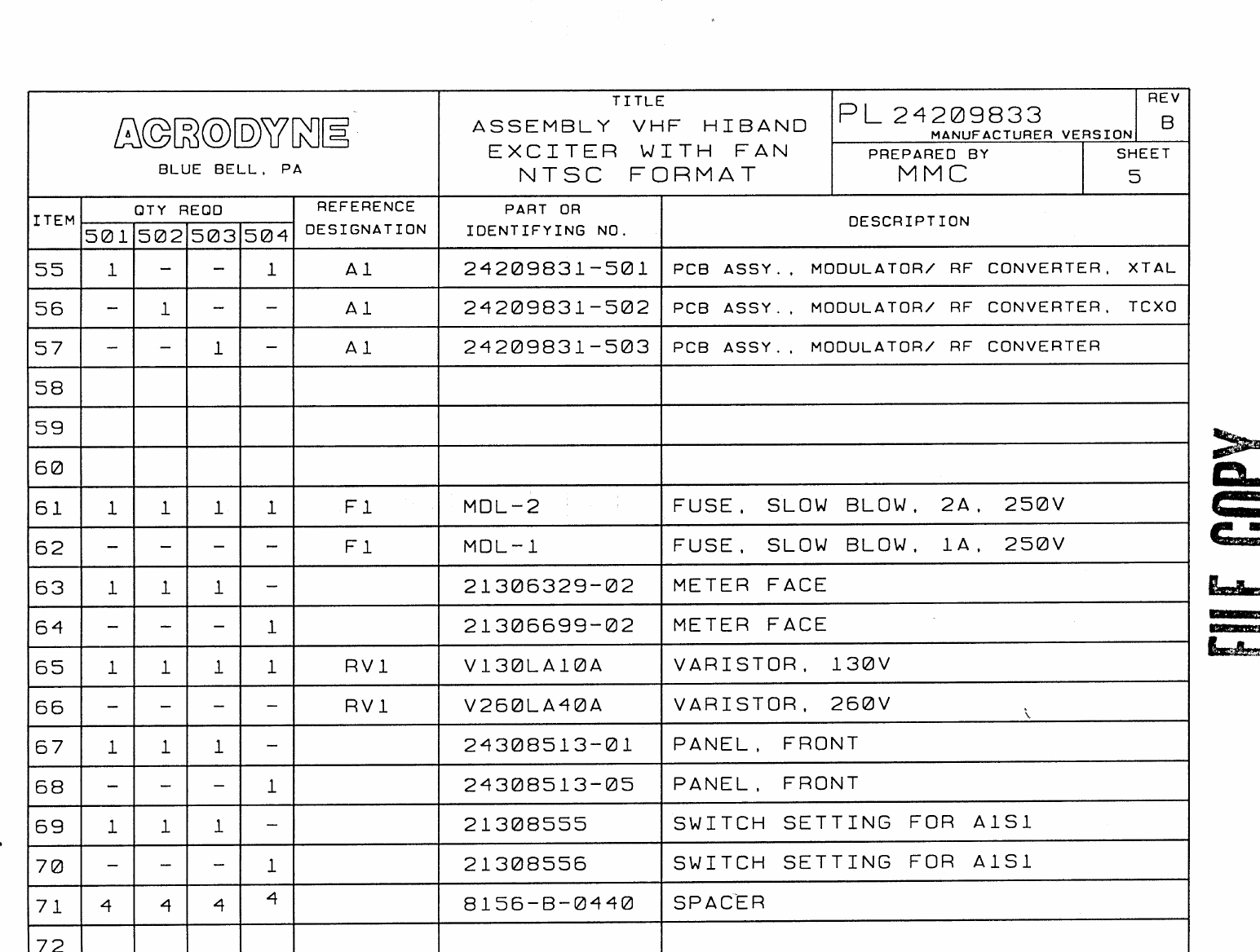
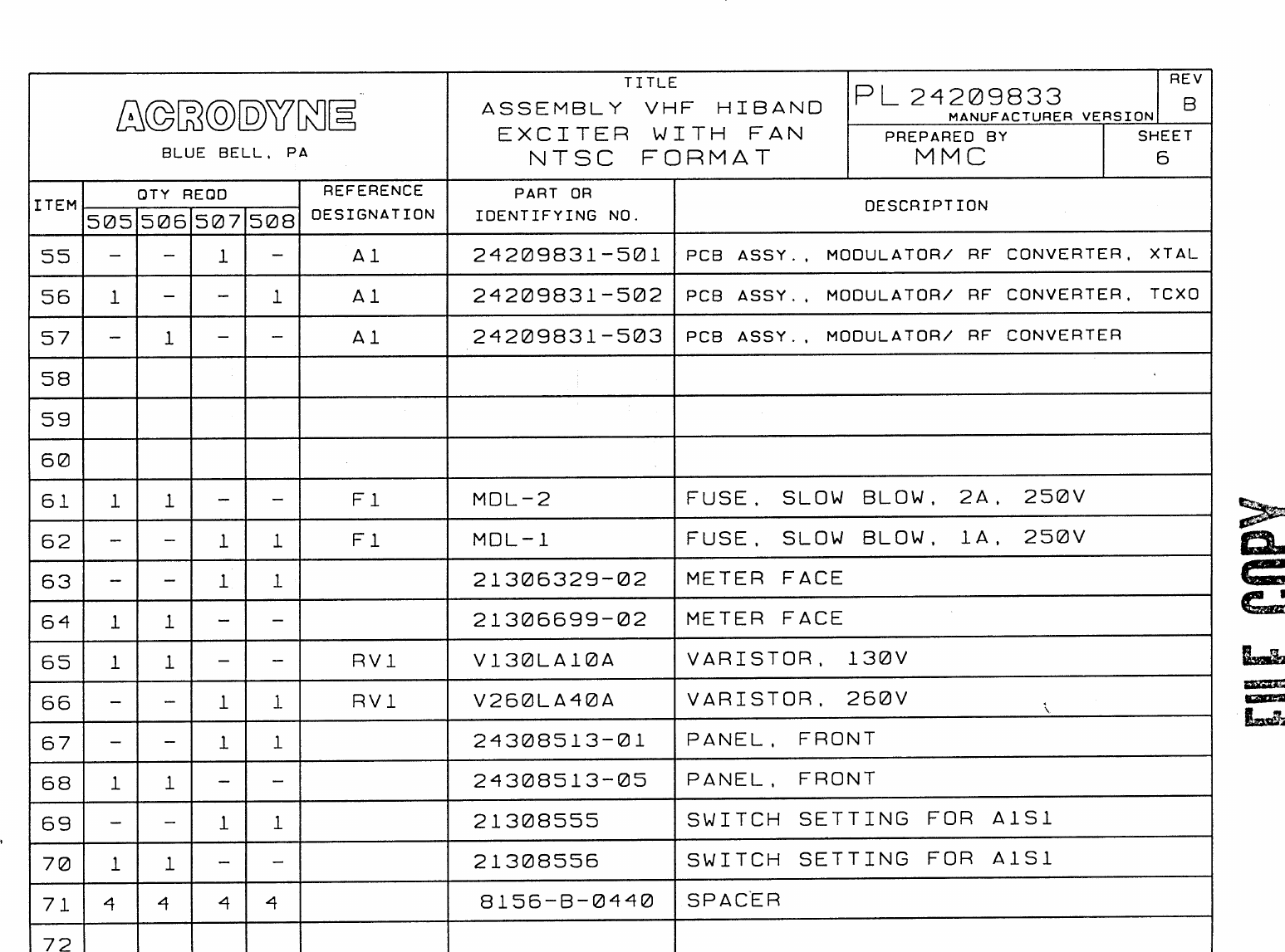
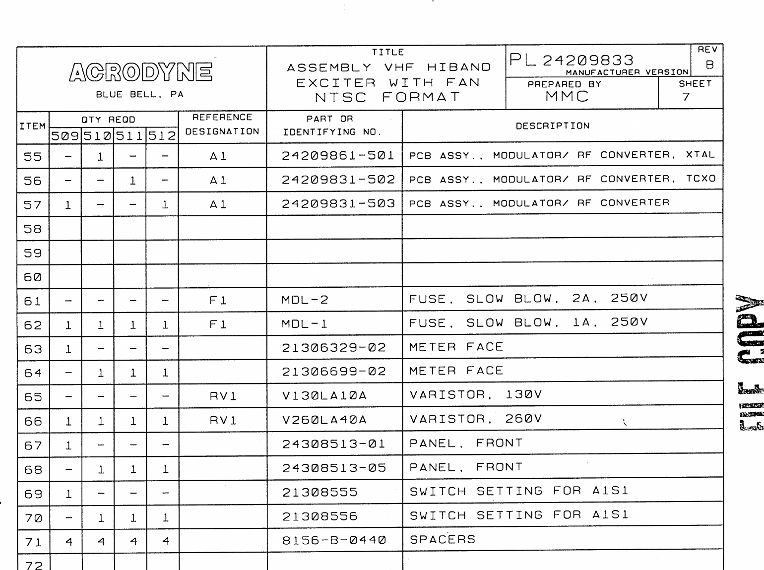
- 1. Part 1 Text and Parts Lists
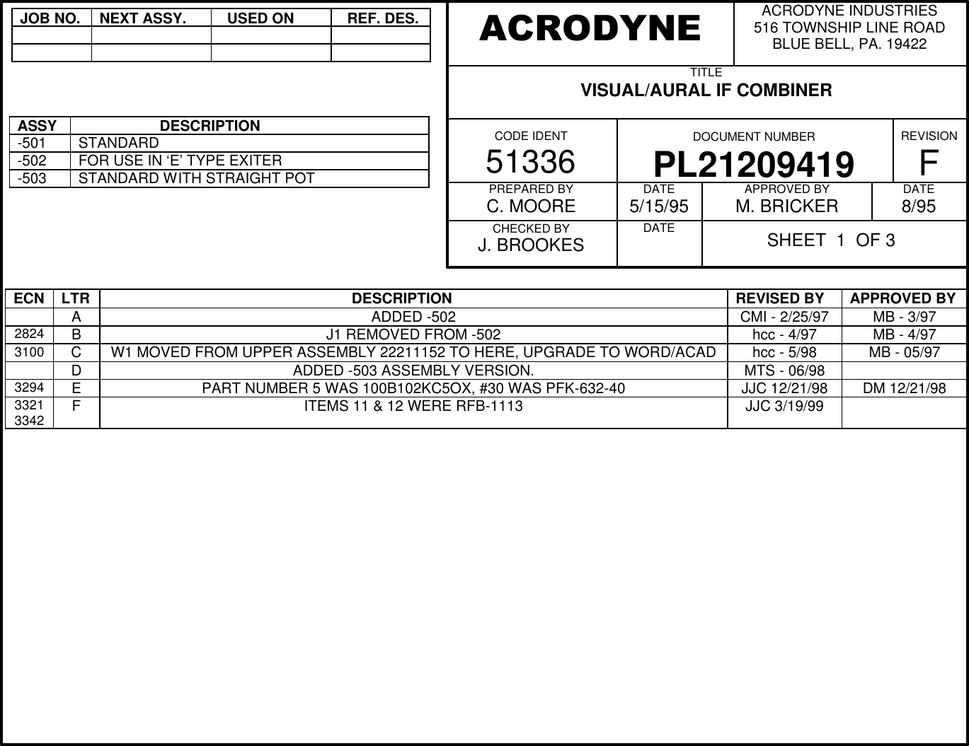
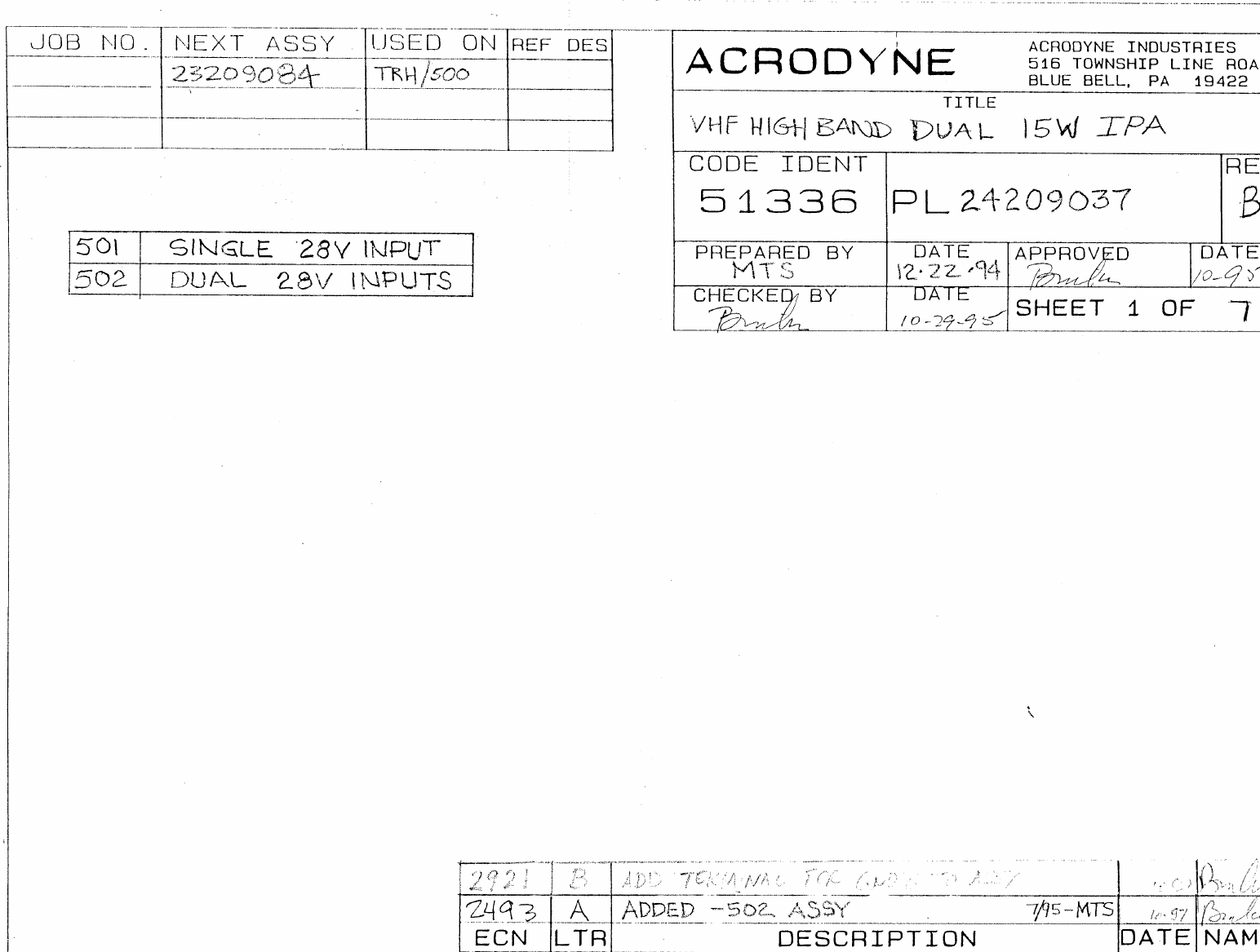
- 2. Part 2 Schematics and drawings
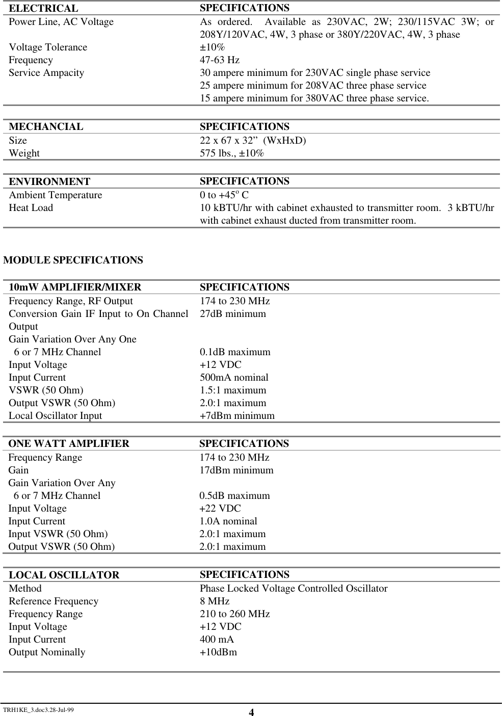
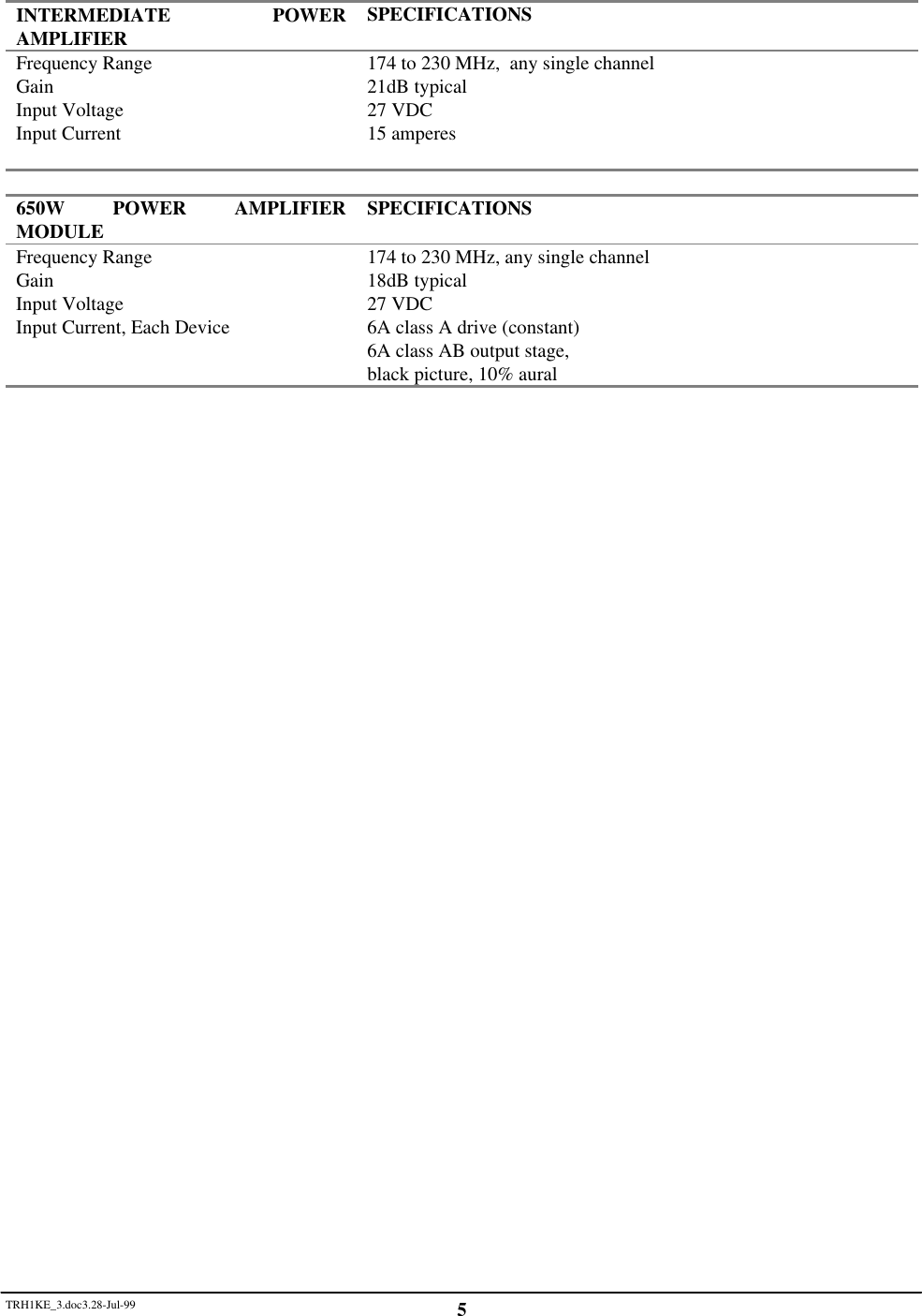
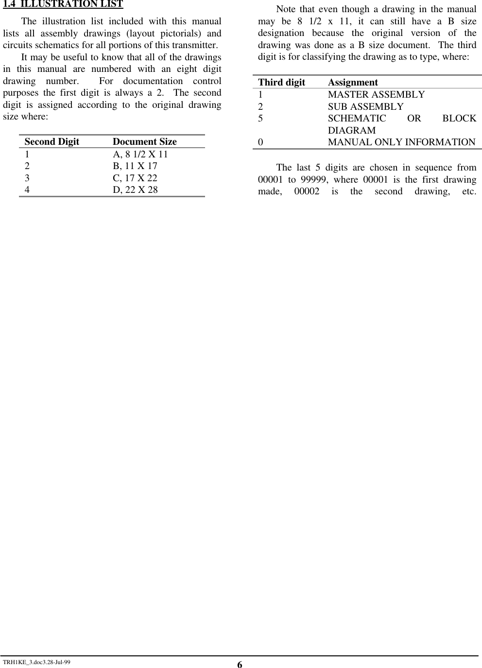
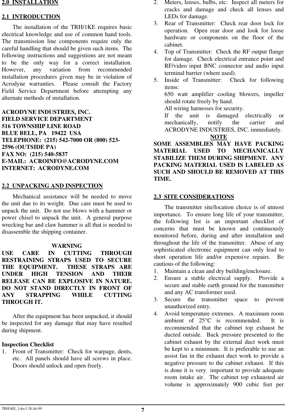
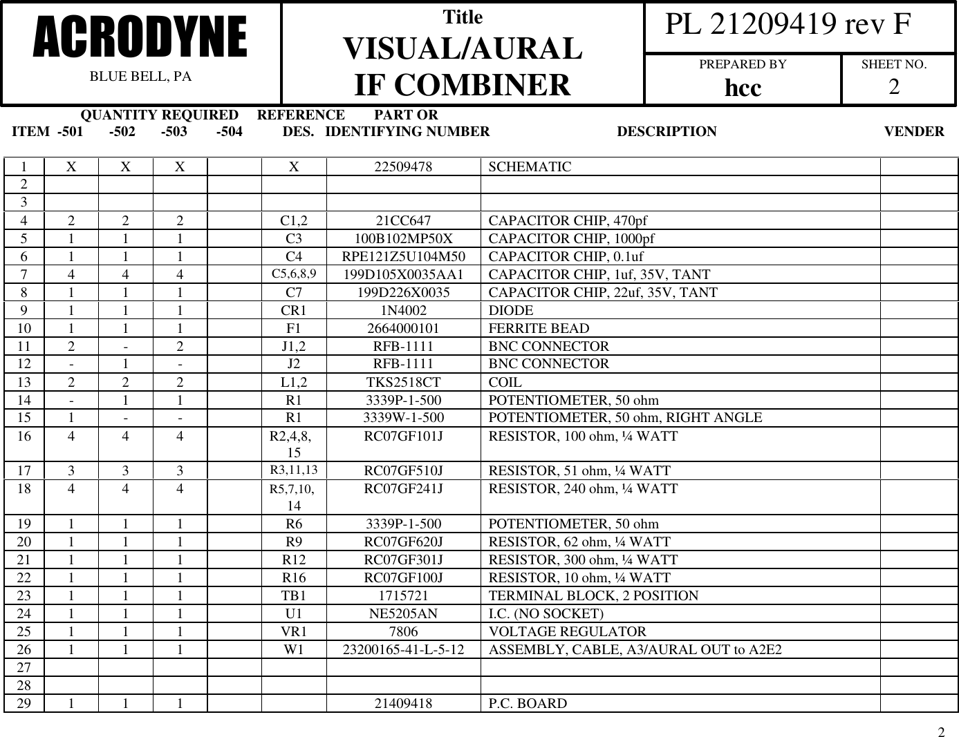
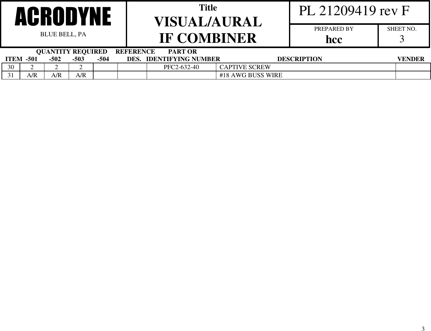
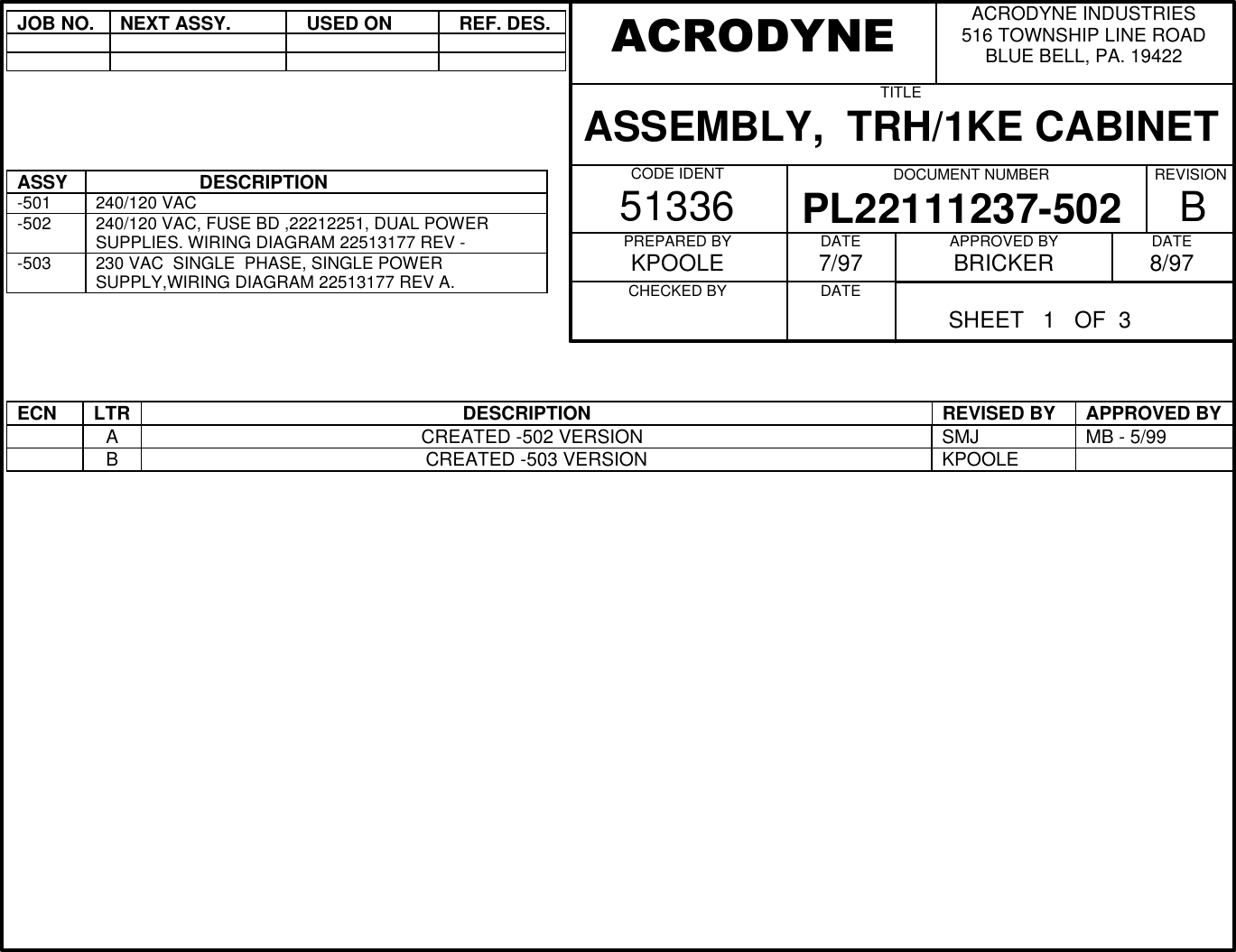
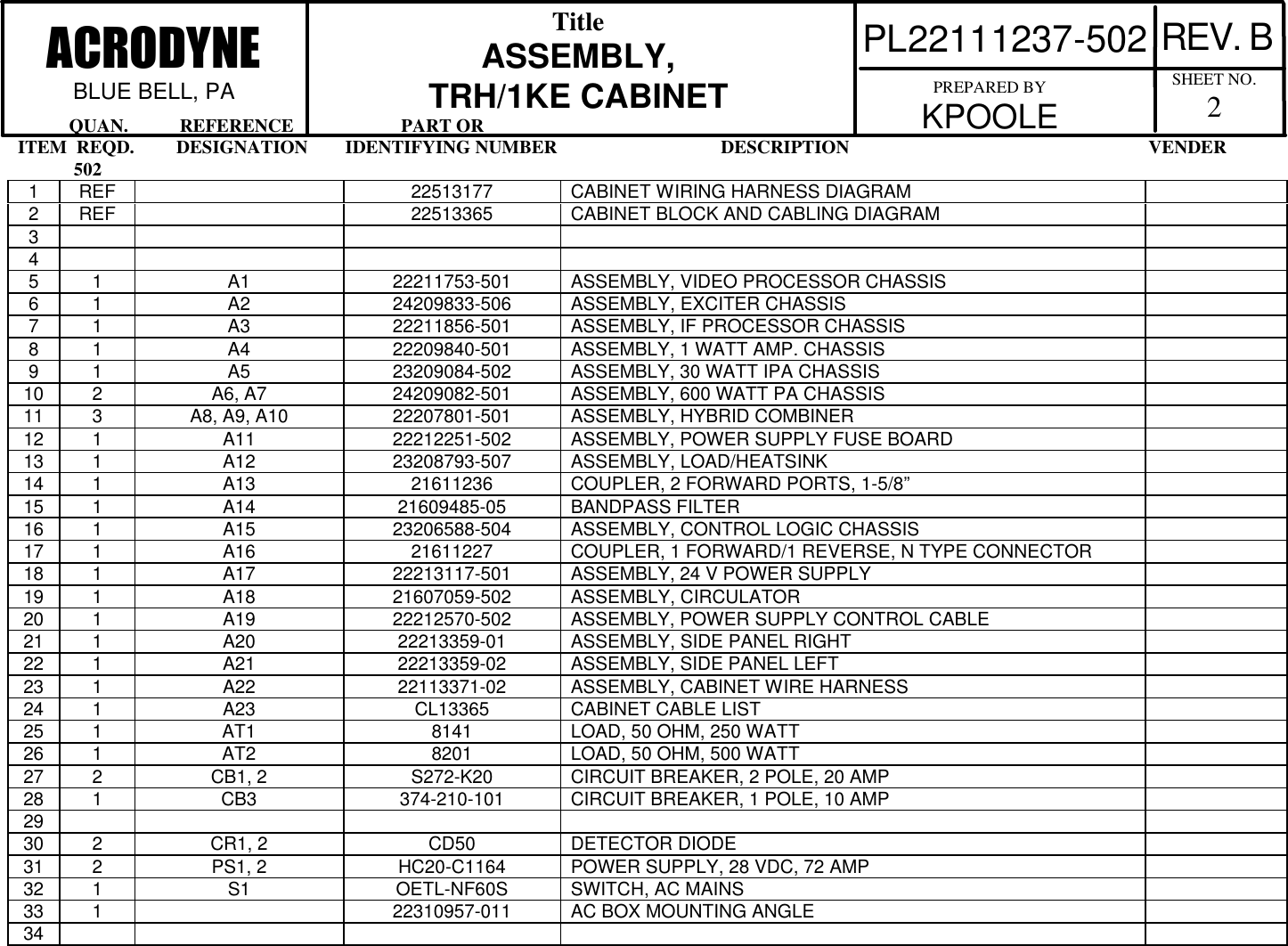
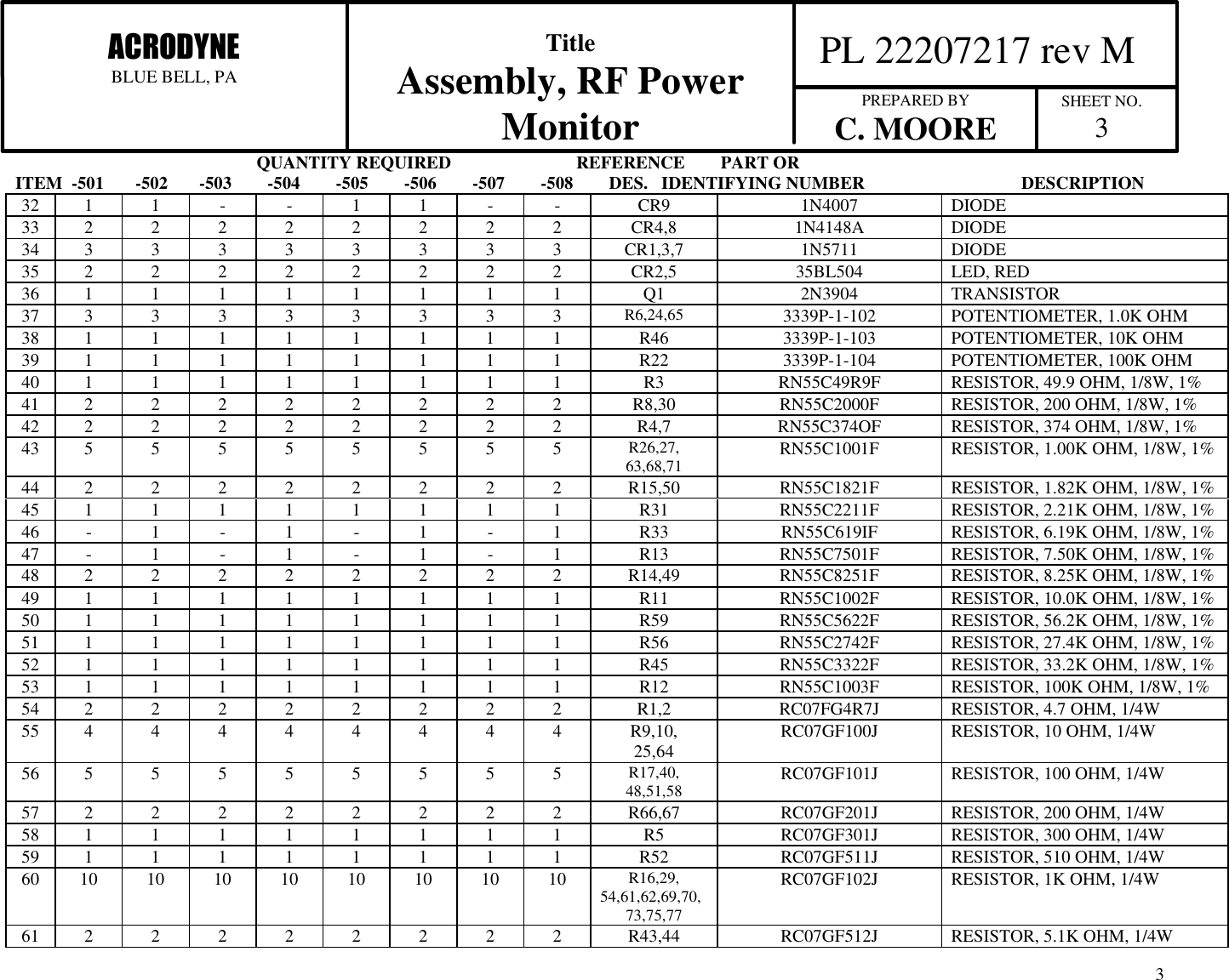
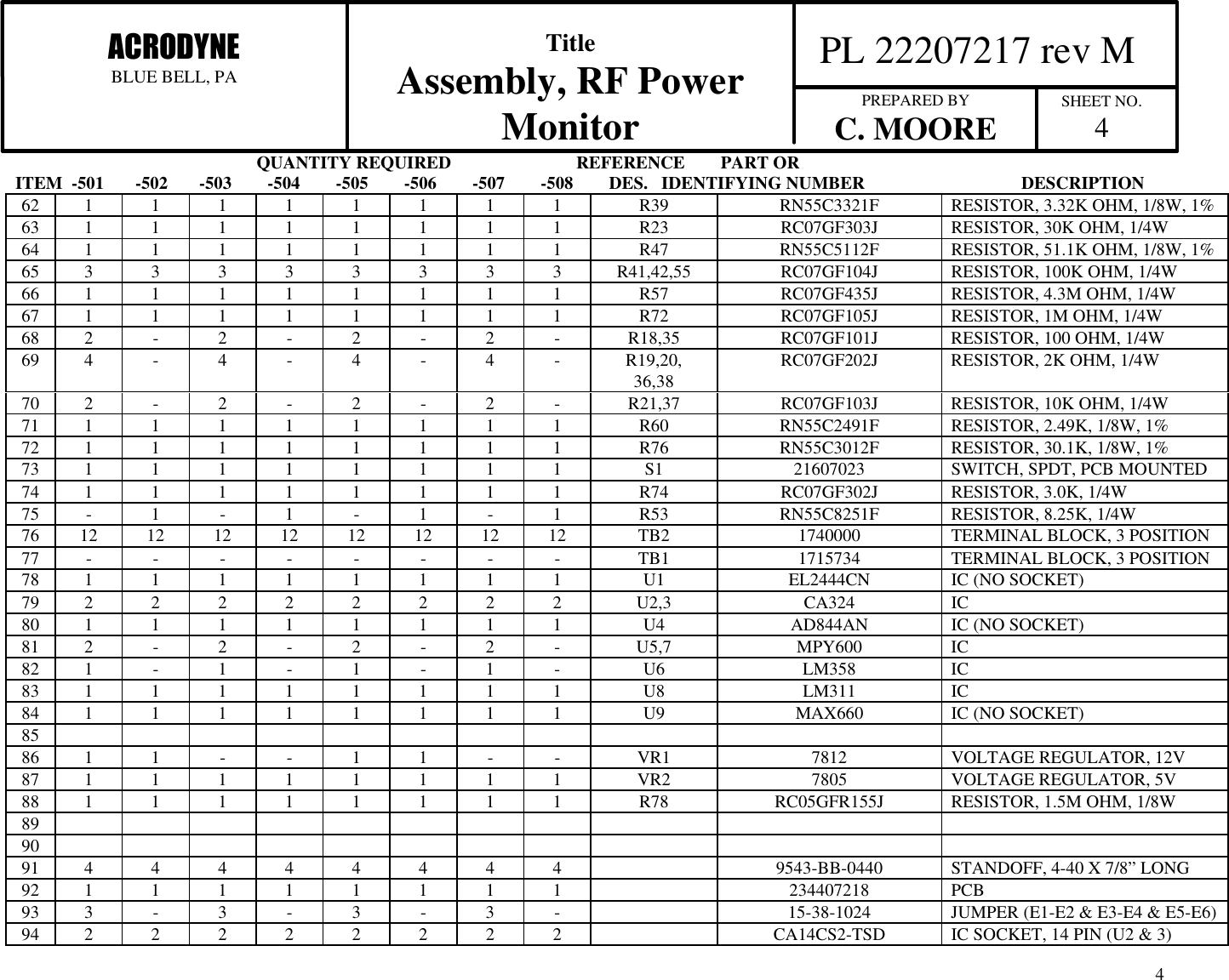
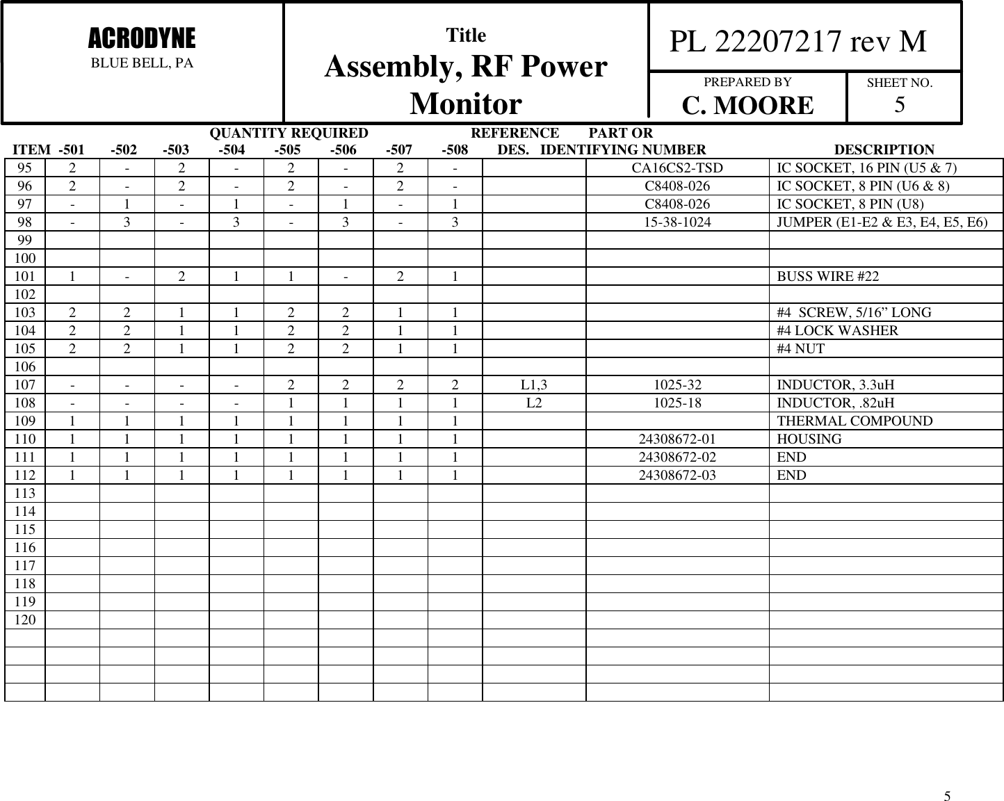
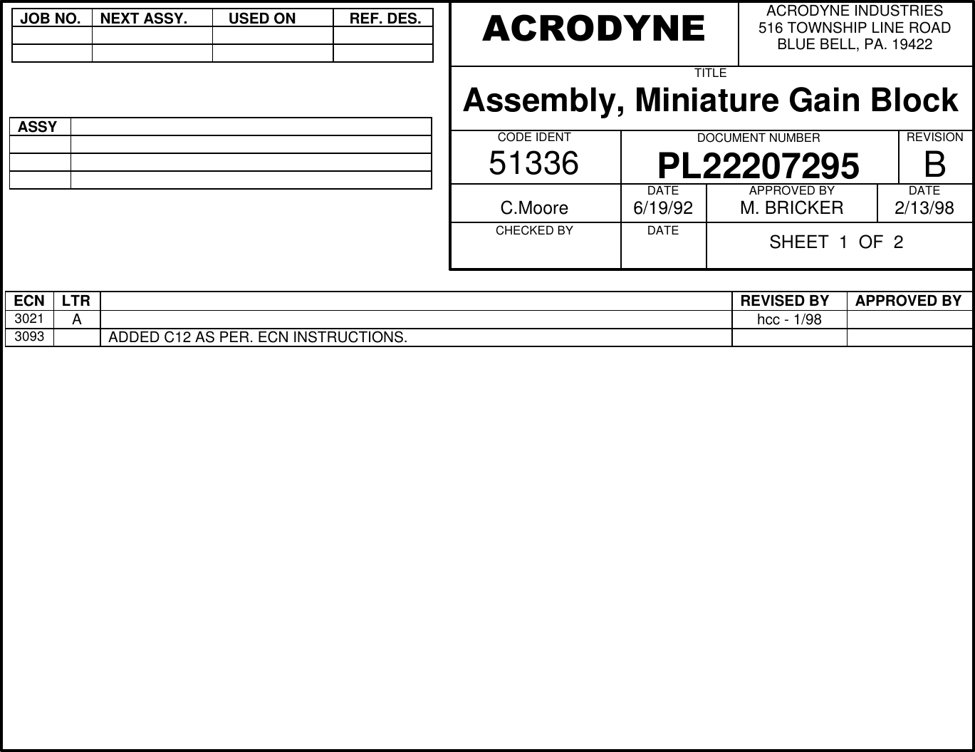
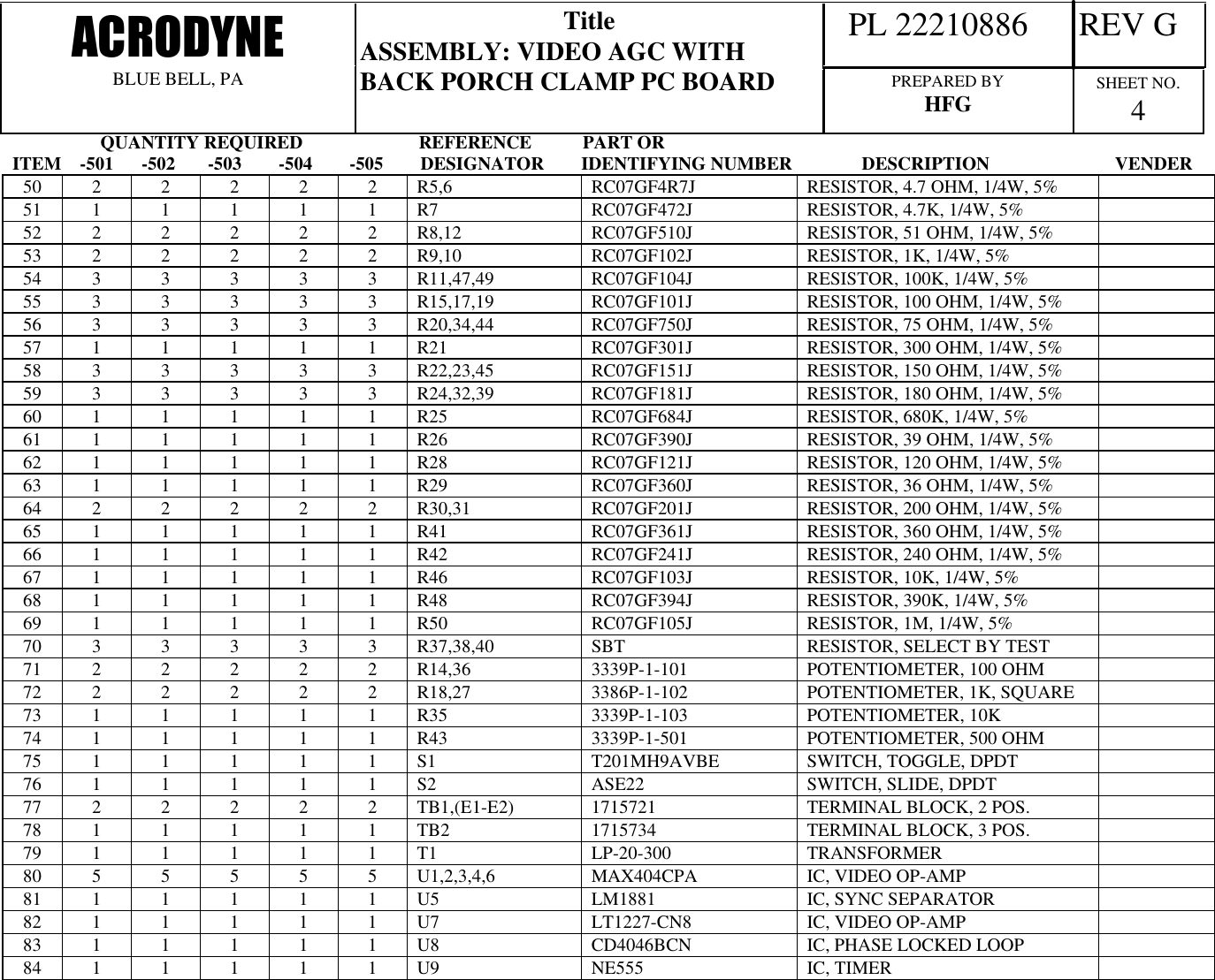
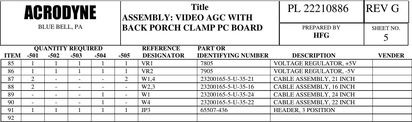
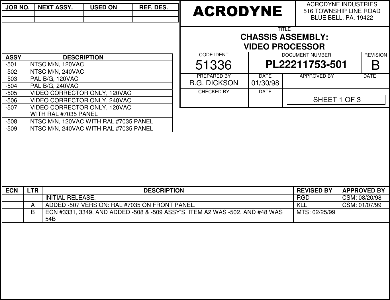
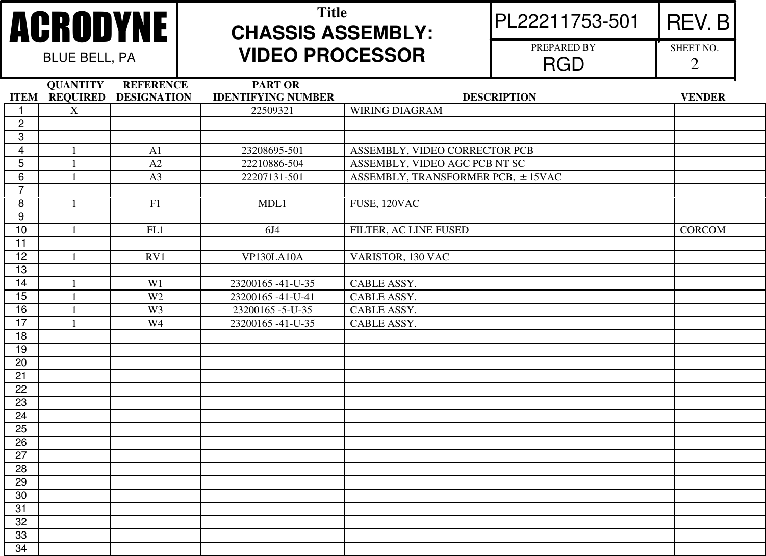
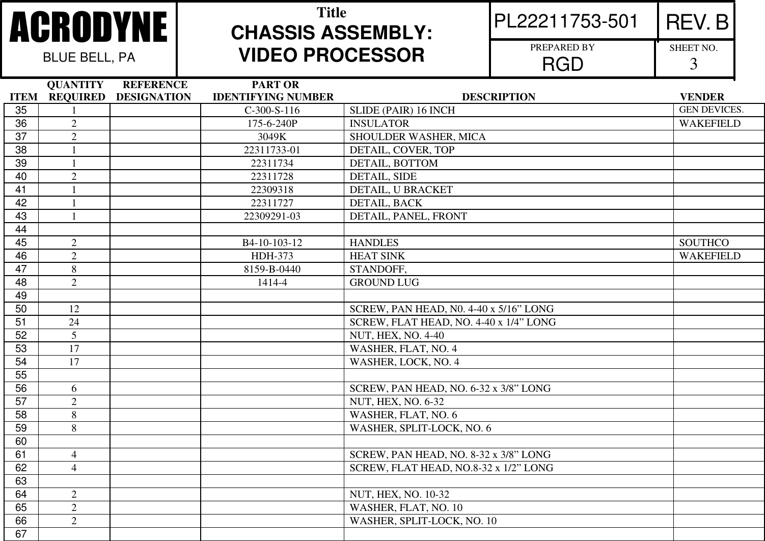
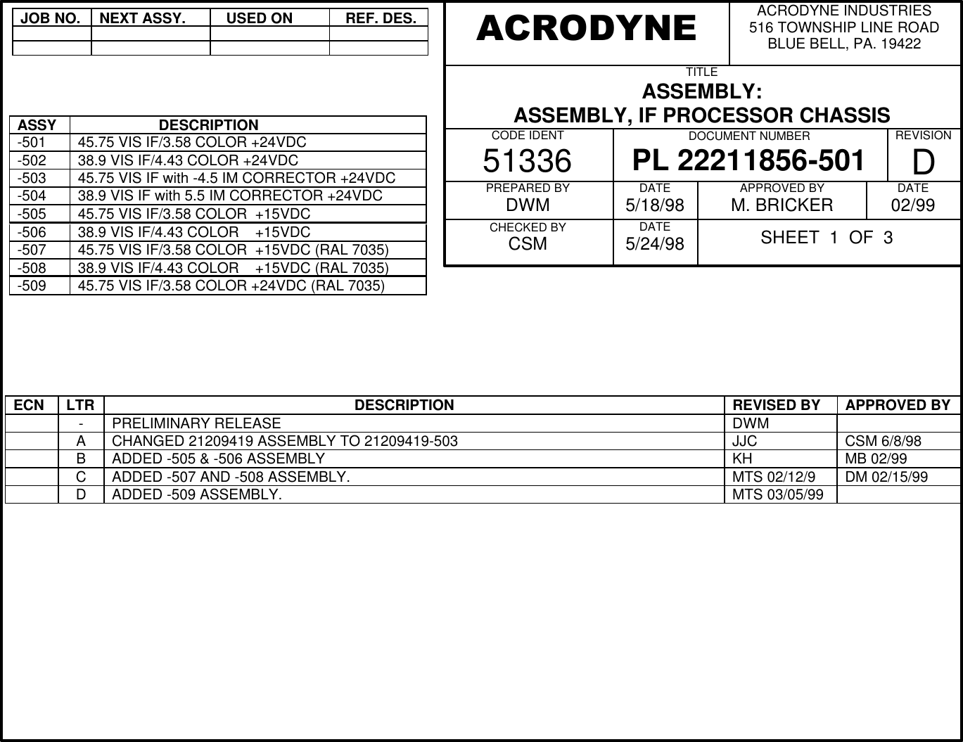
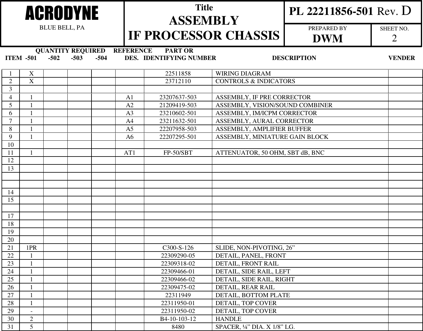
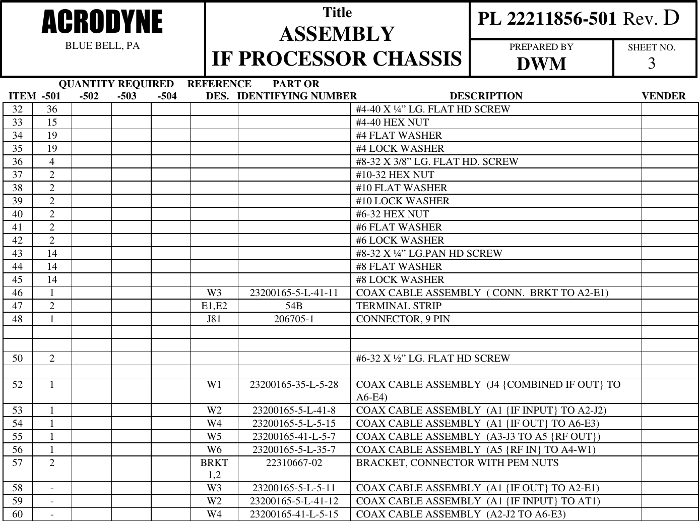
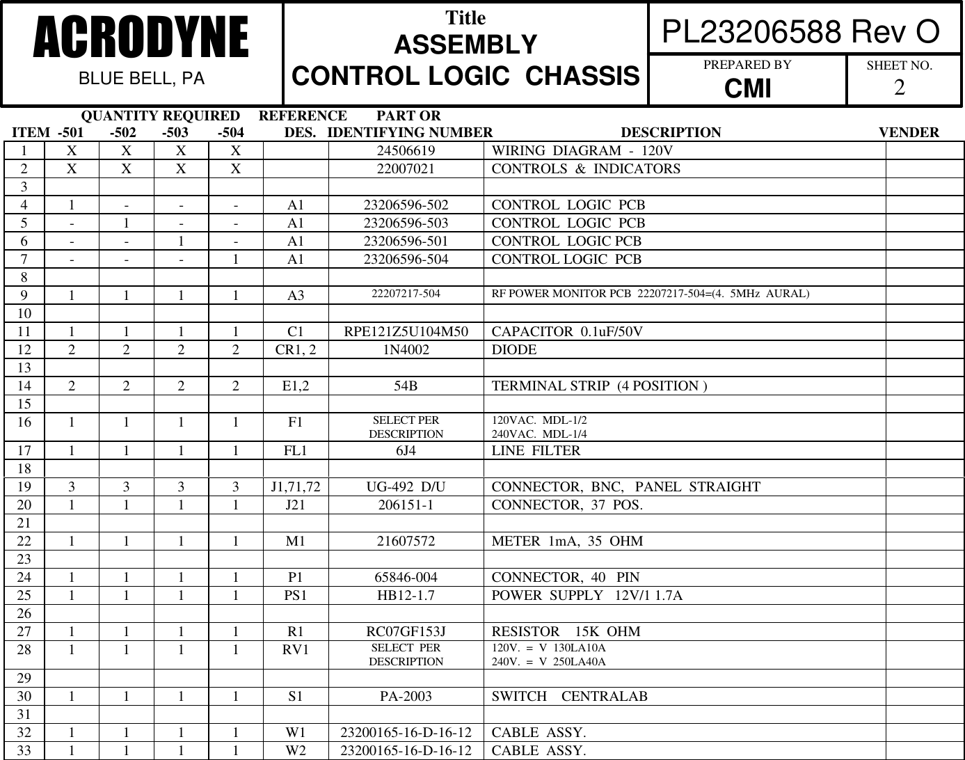
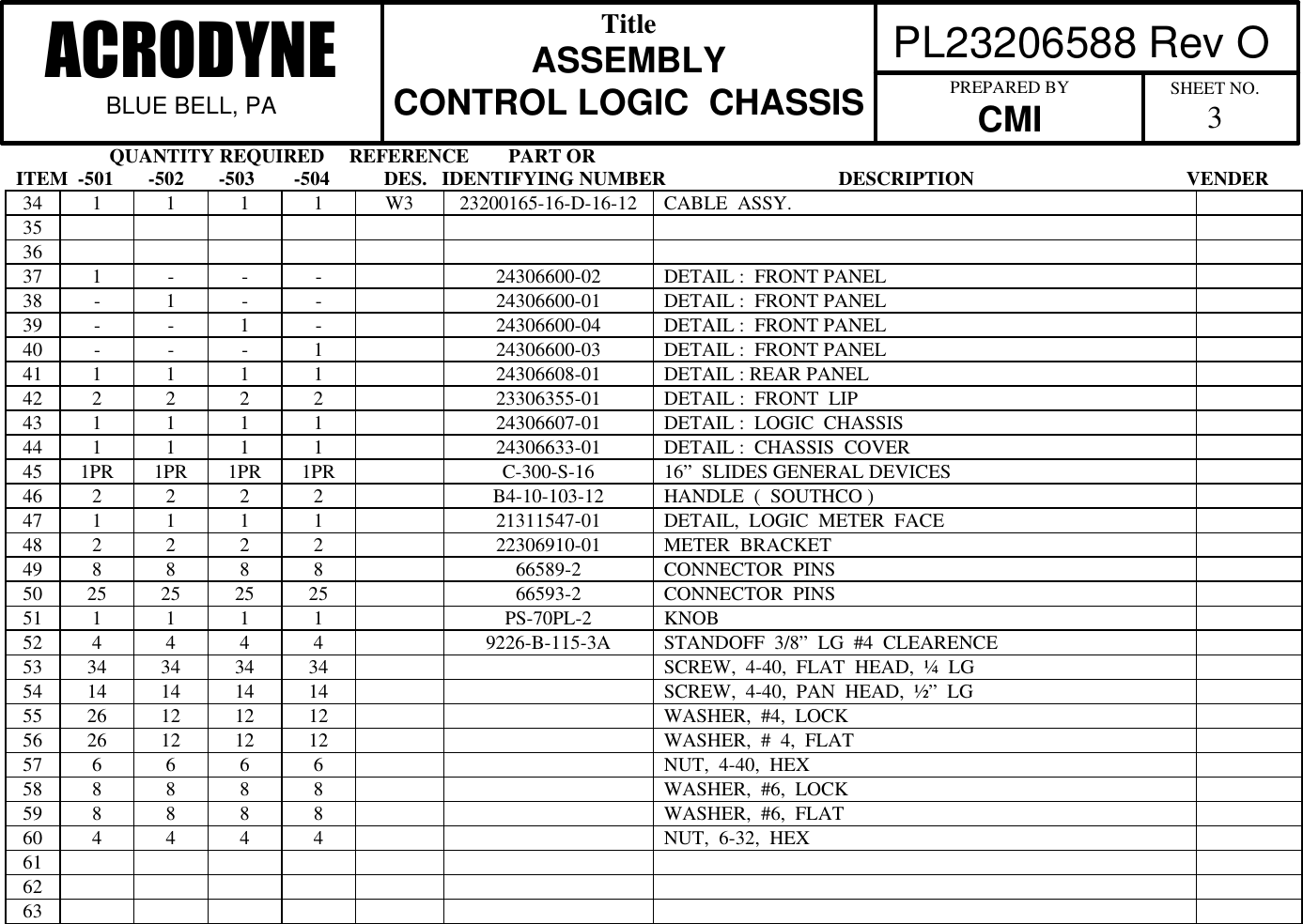
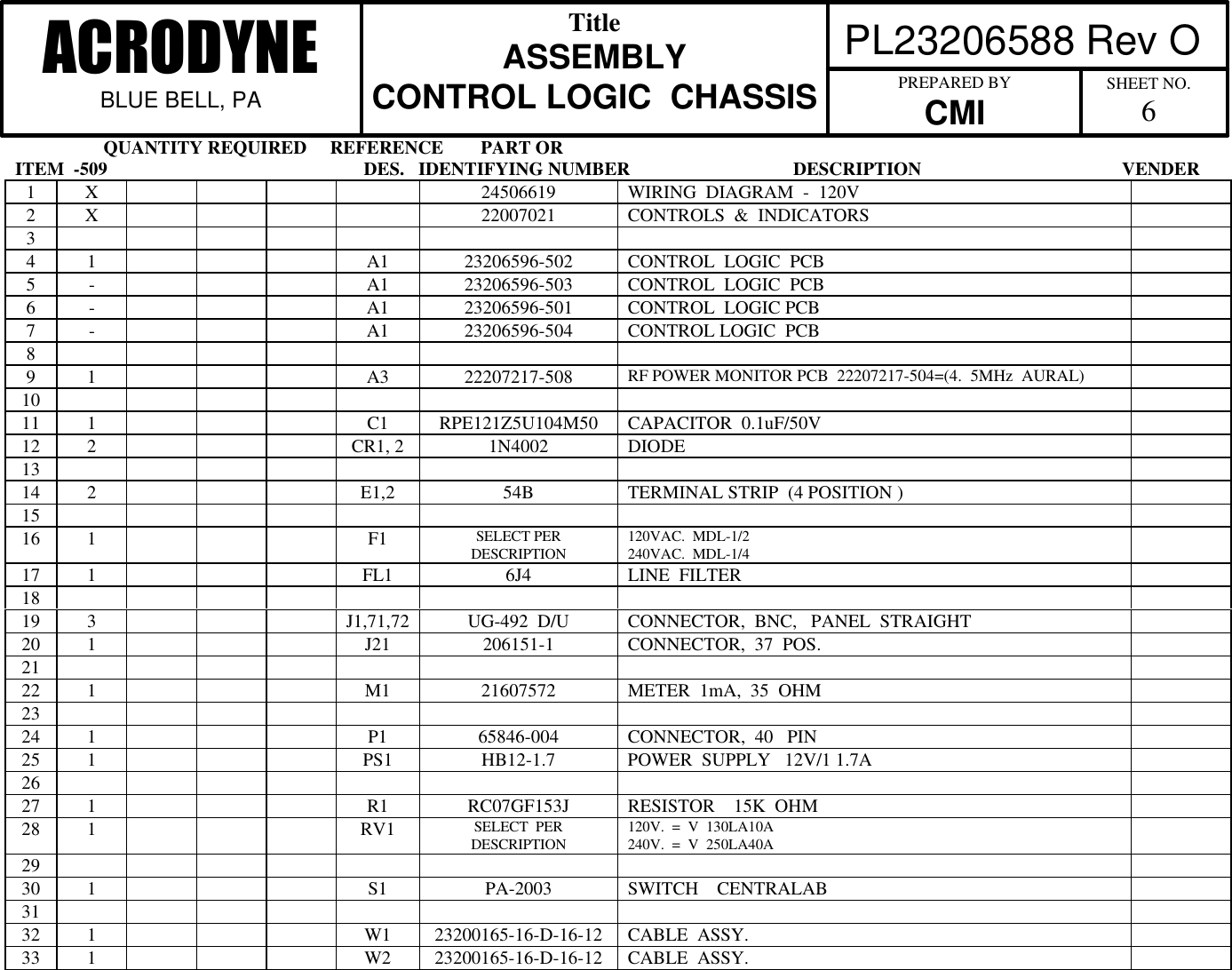
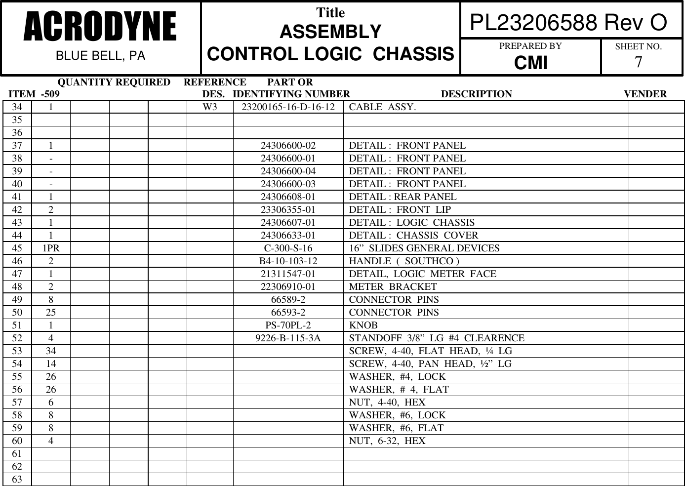
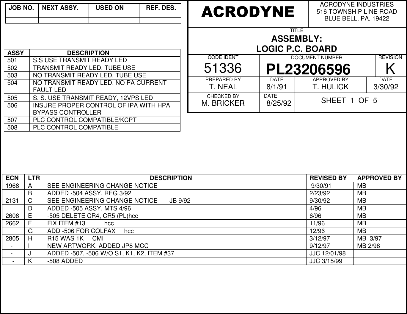
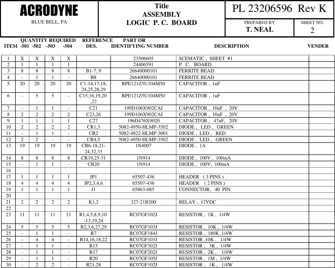
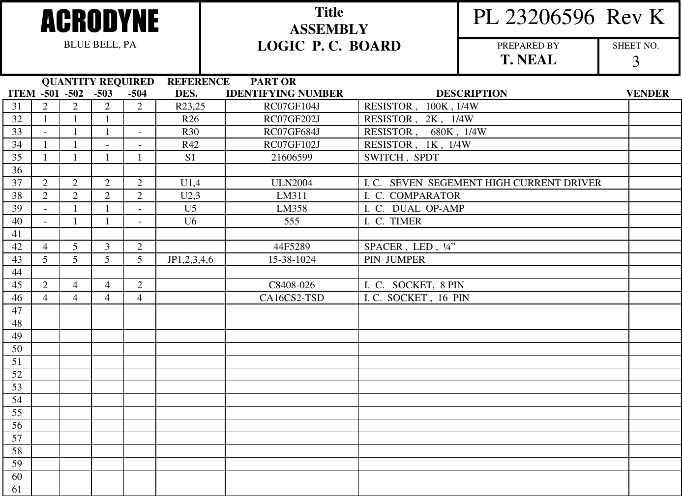
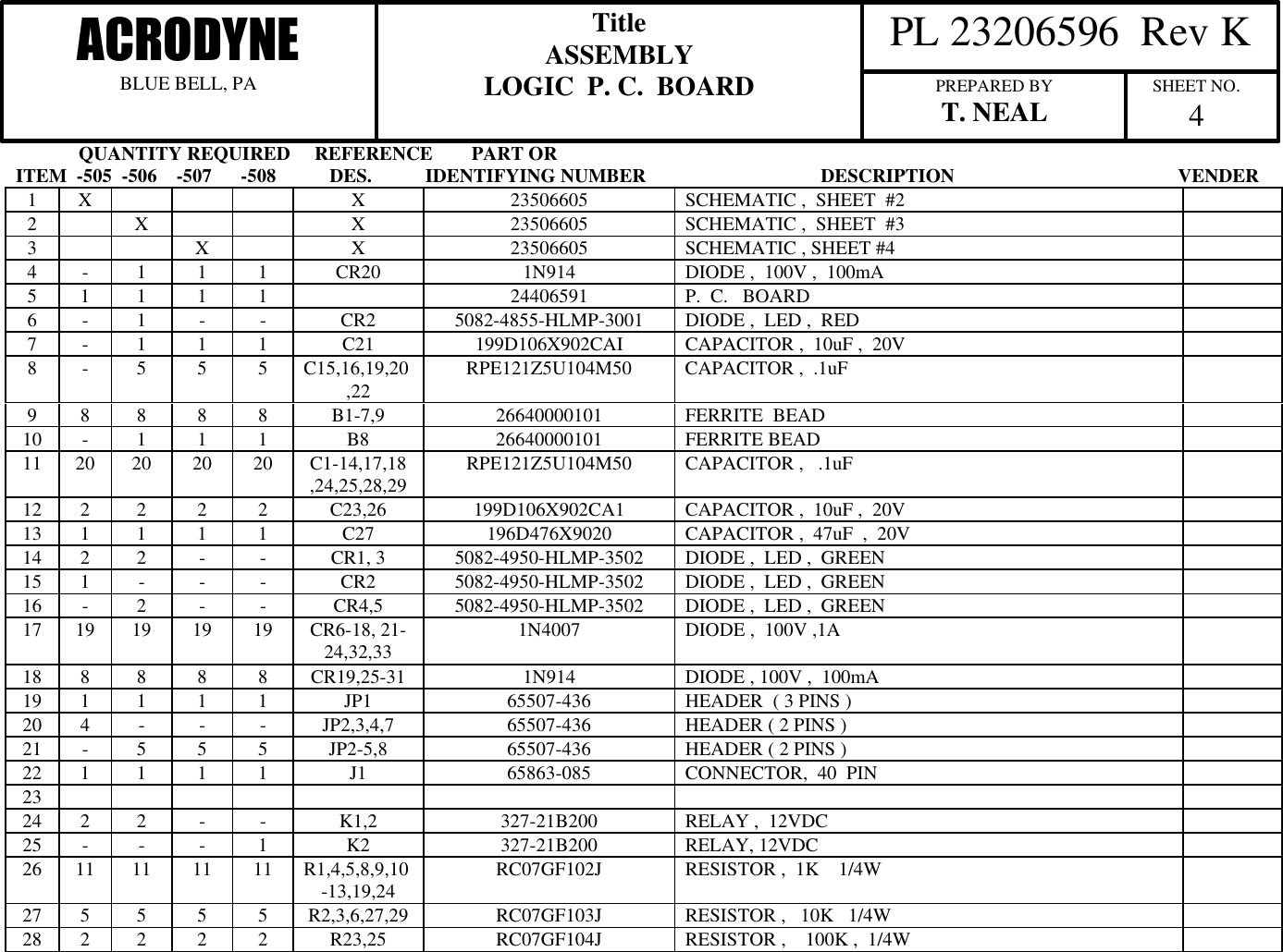
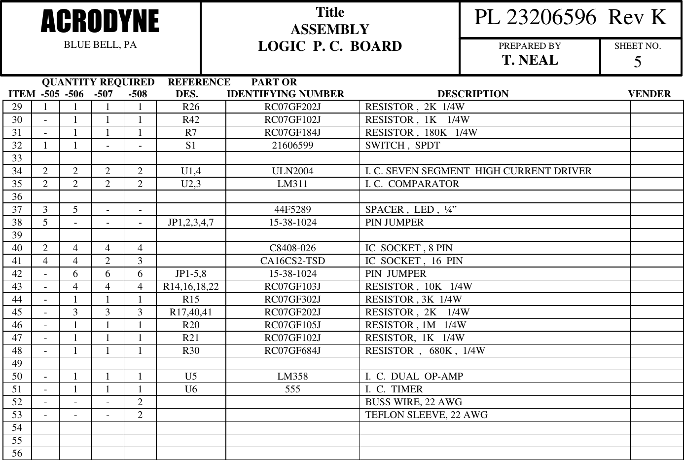
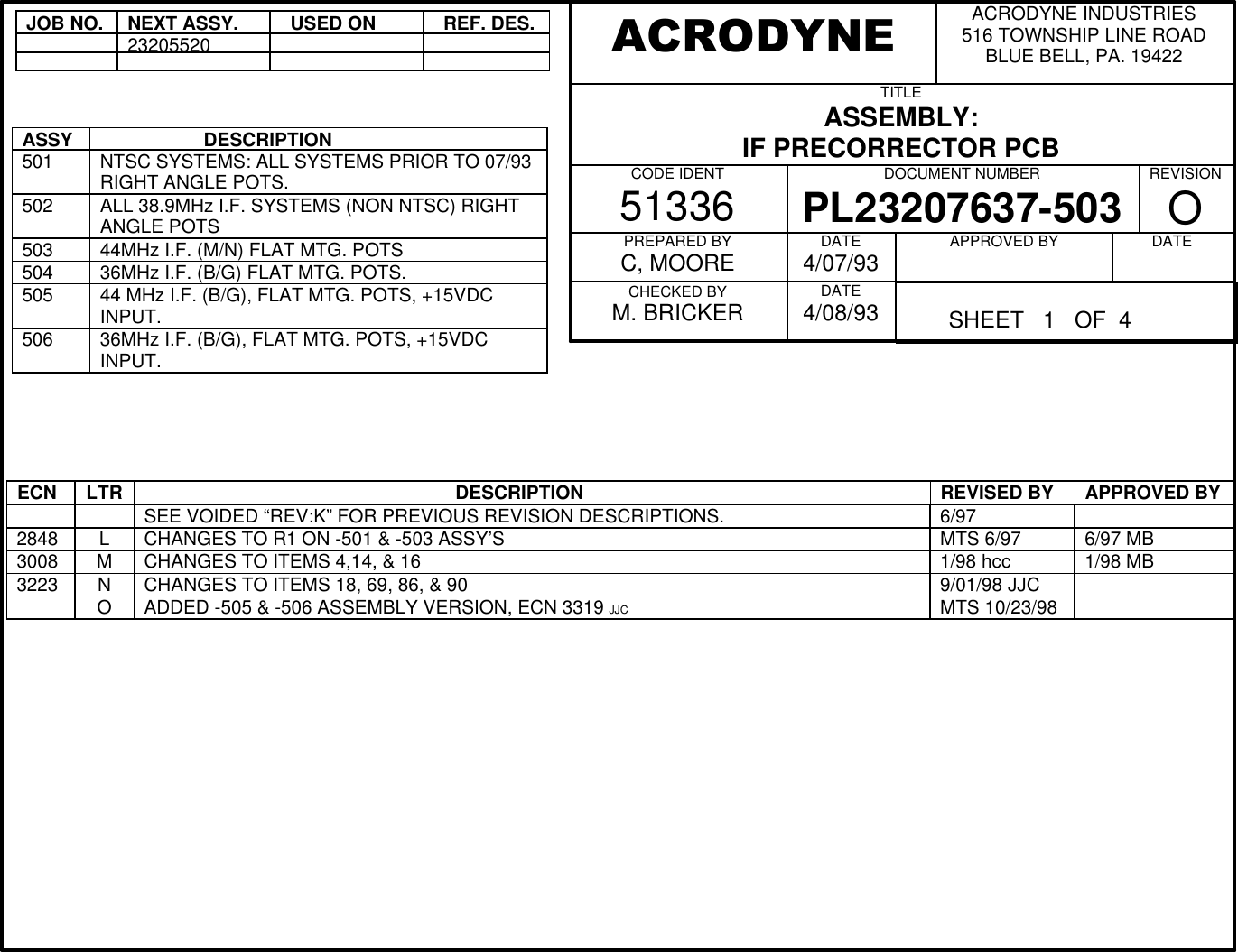
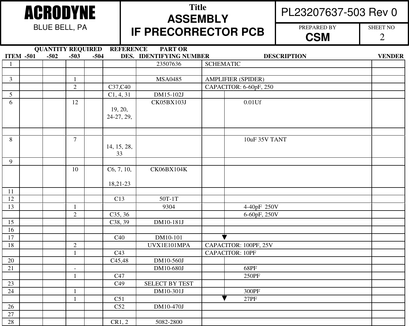
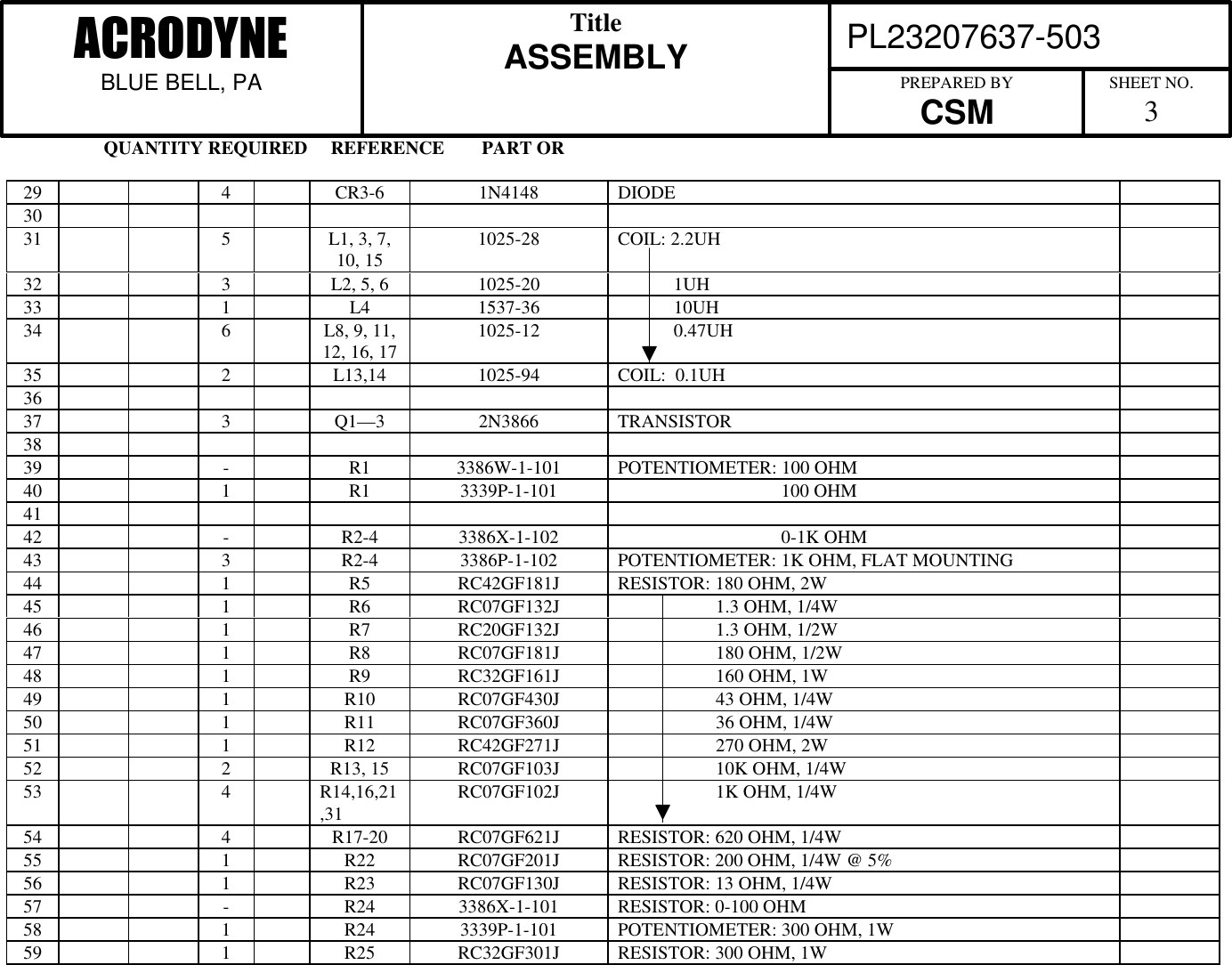
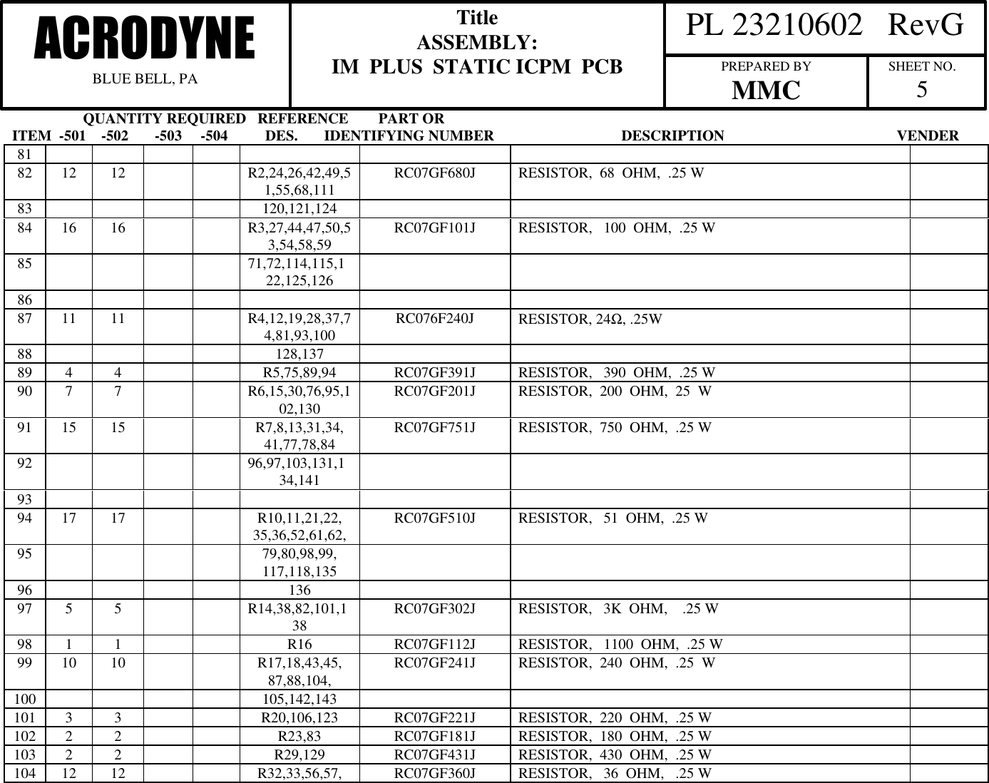
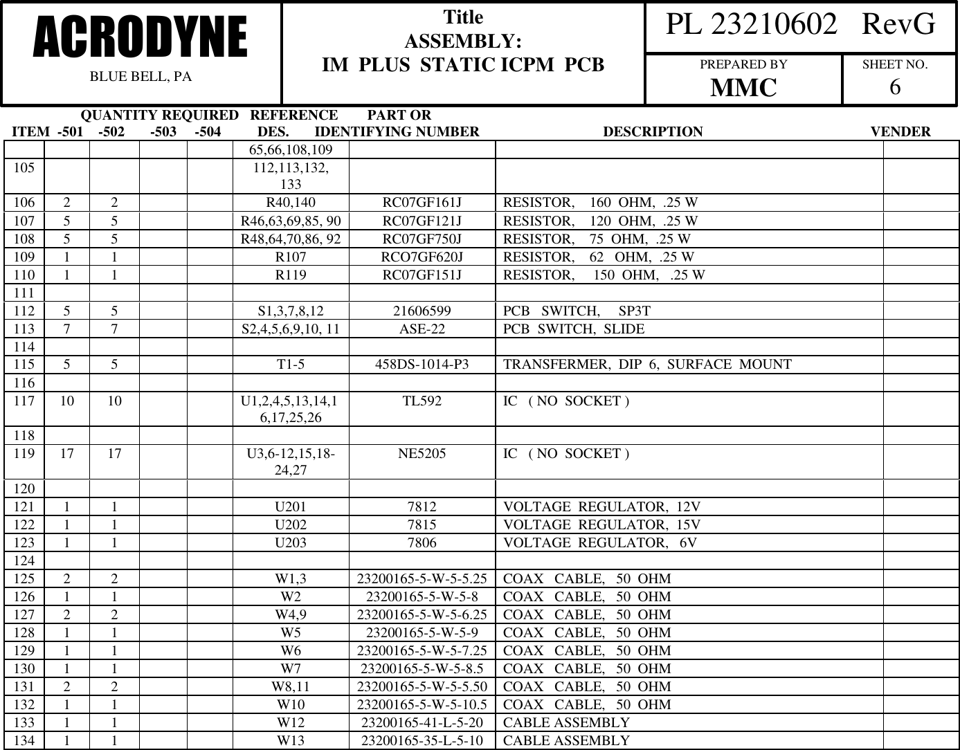
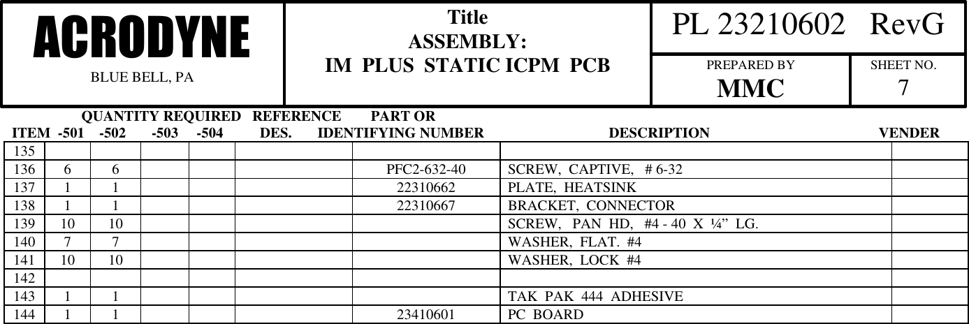
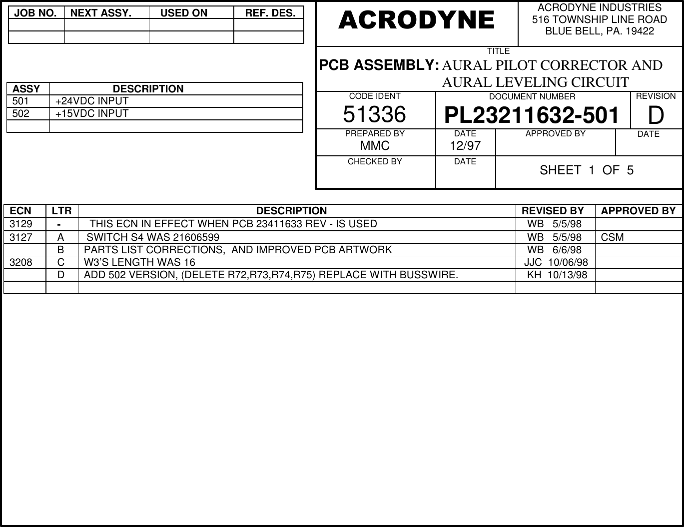
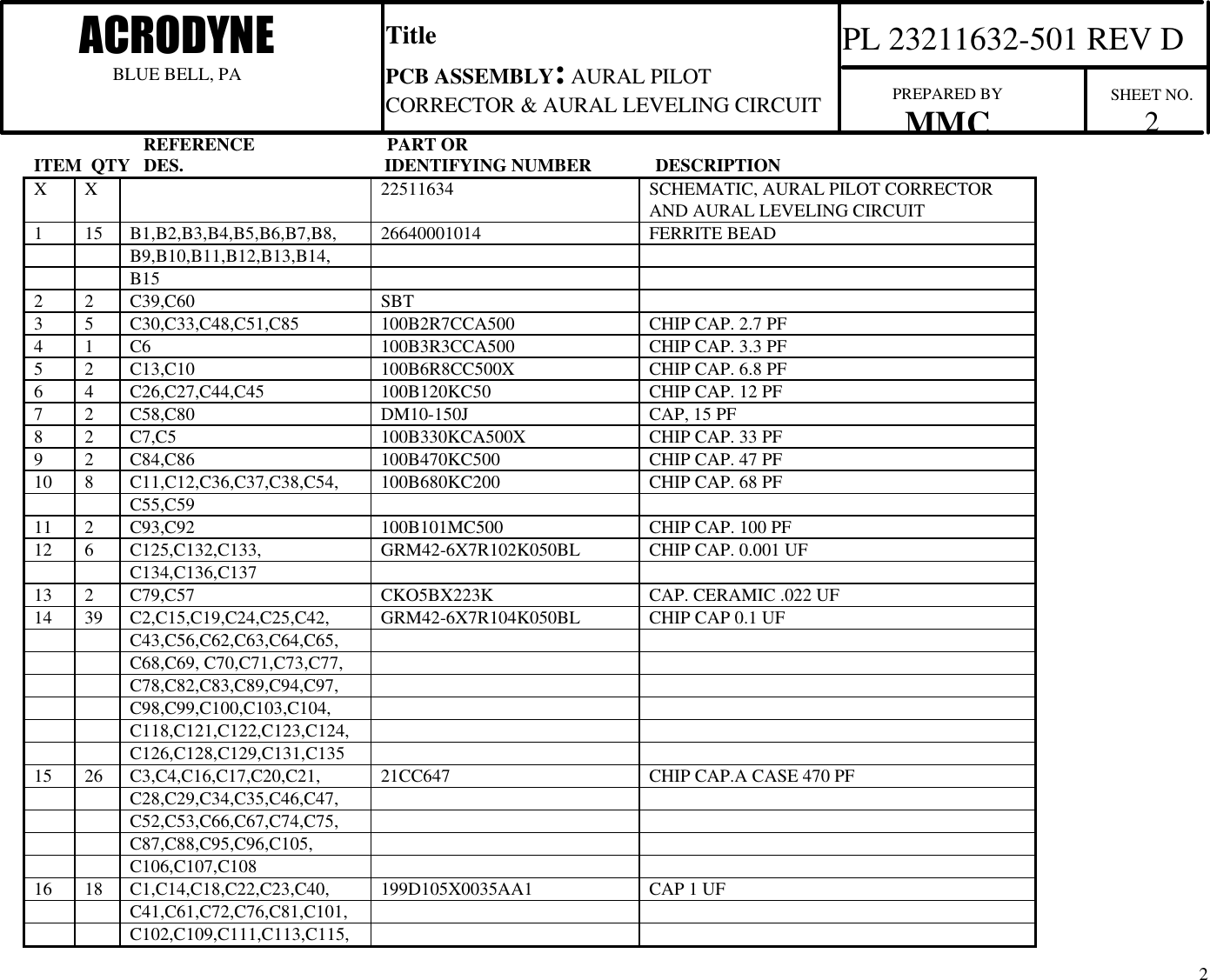
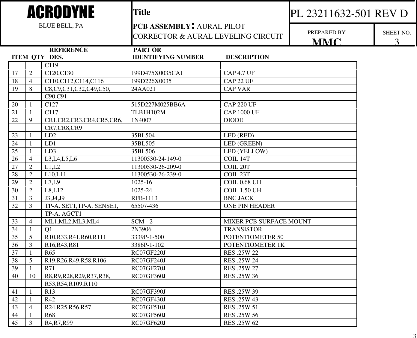
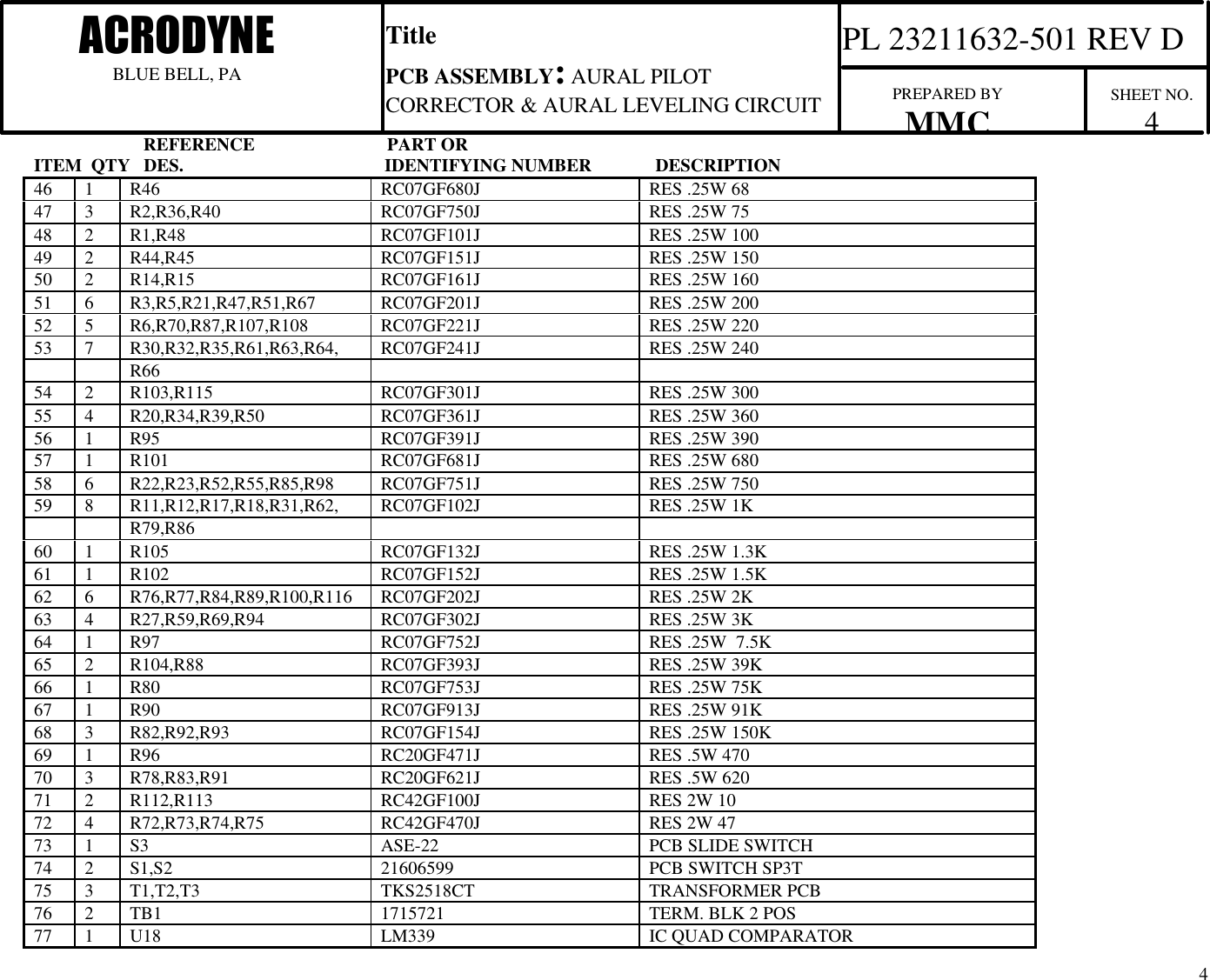
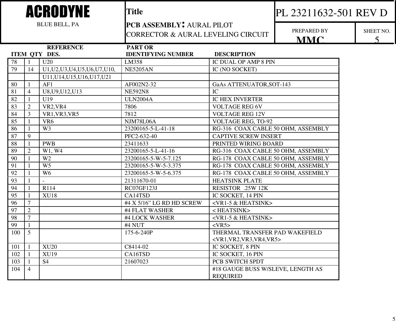
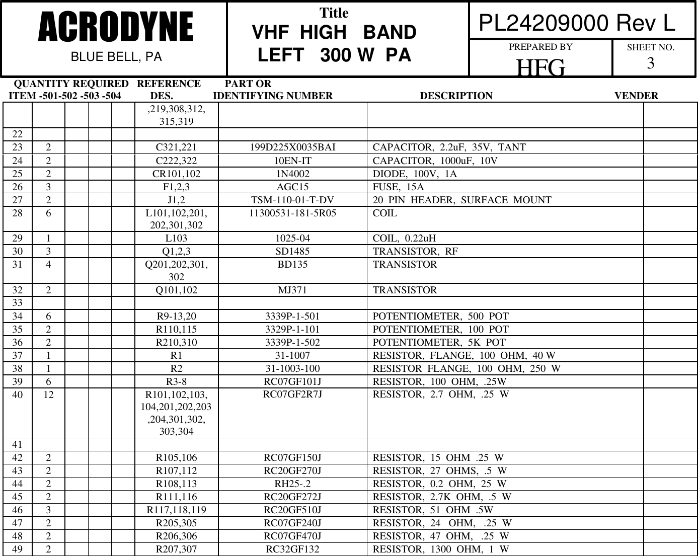
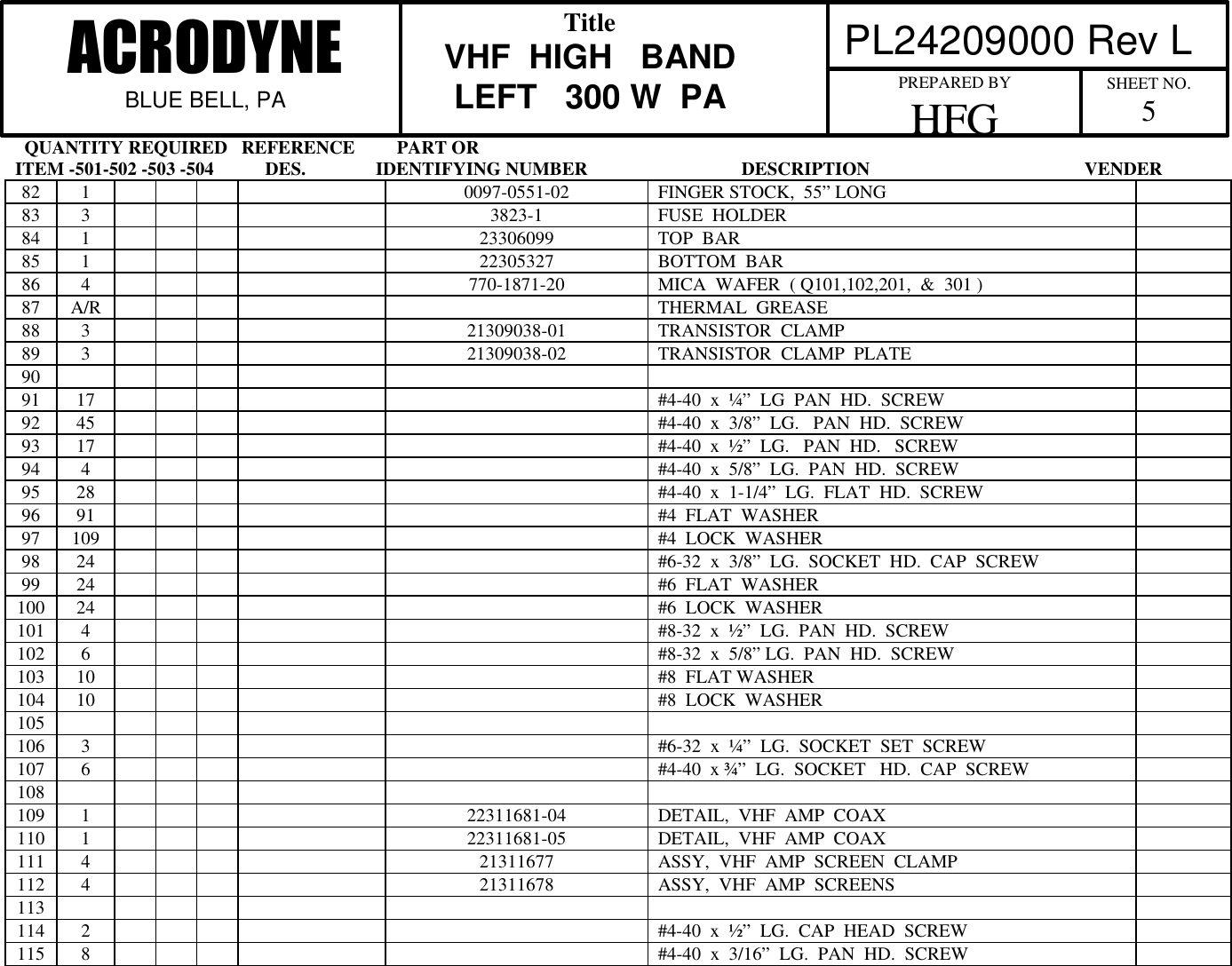
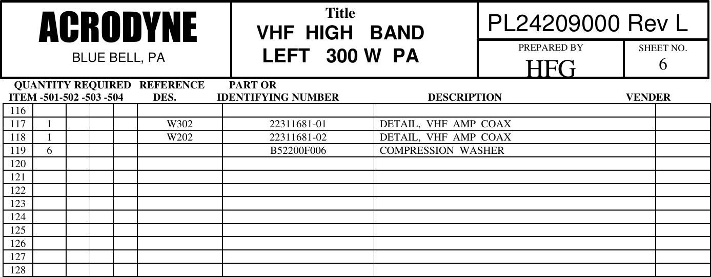
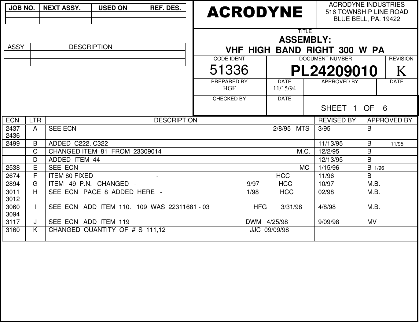
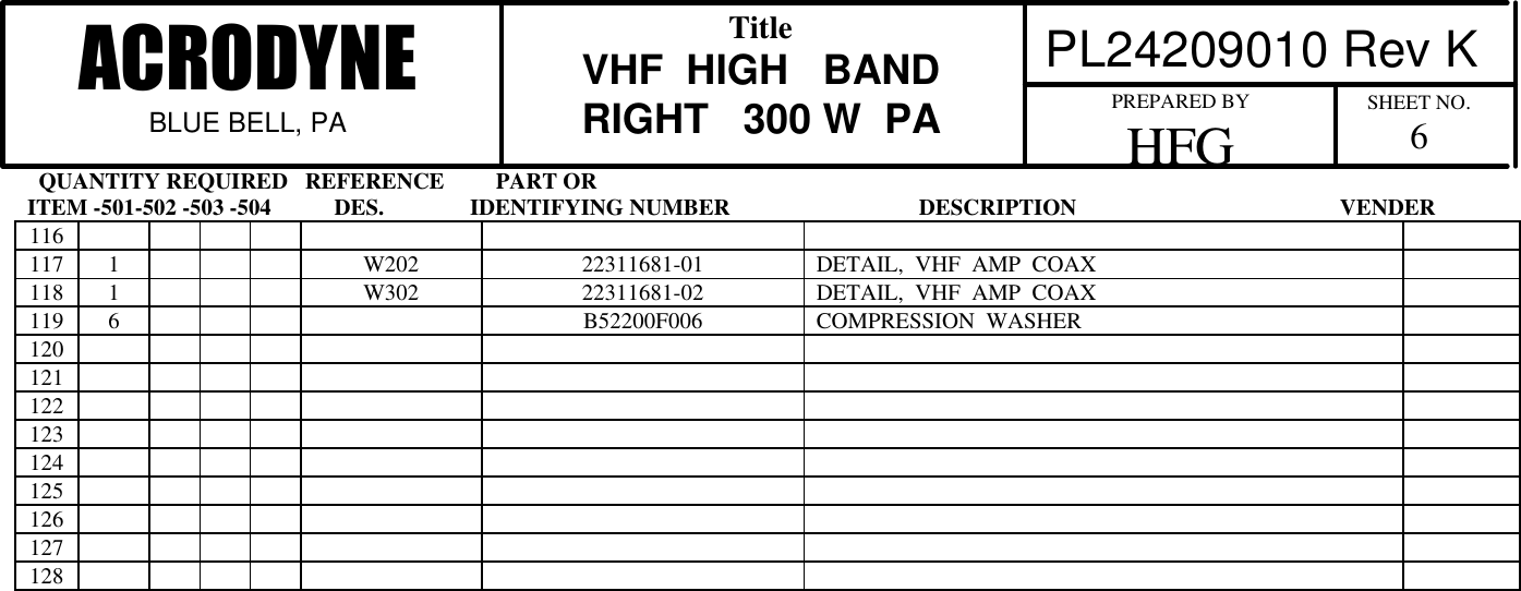
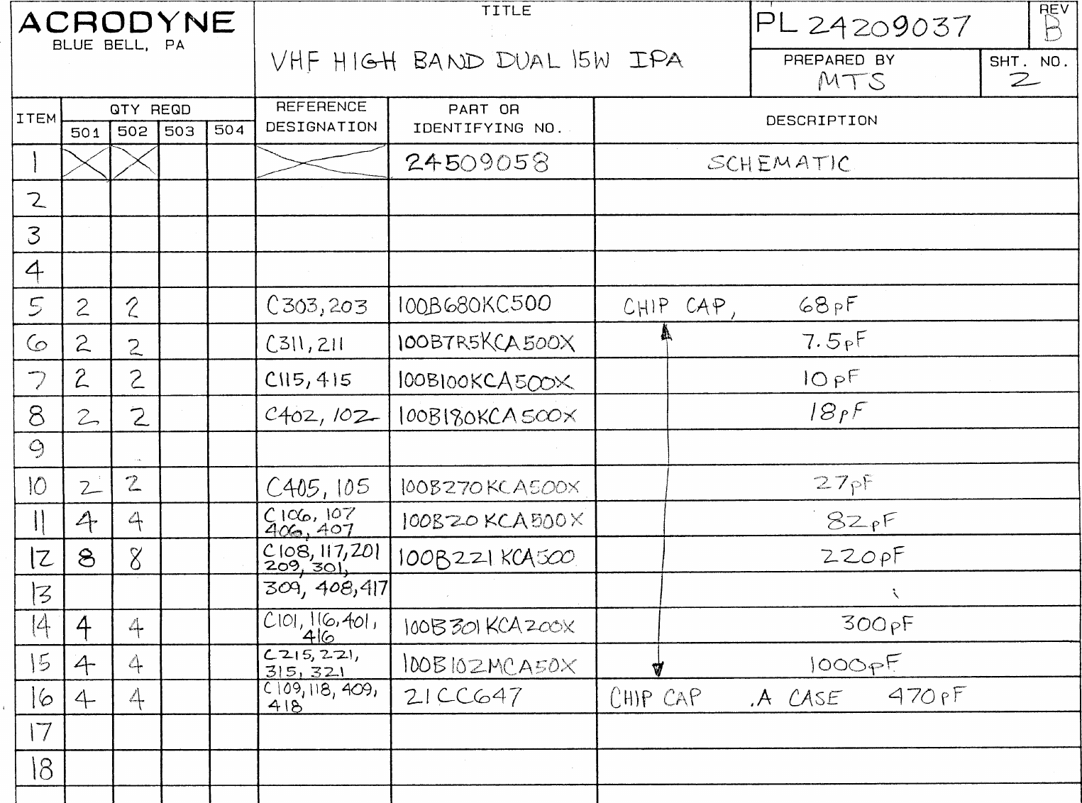
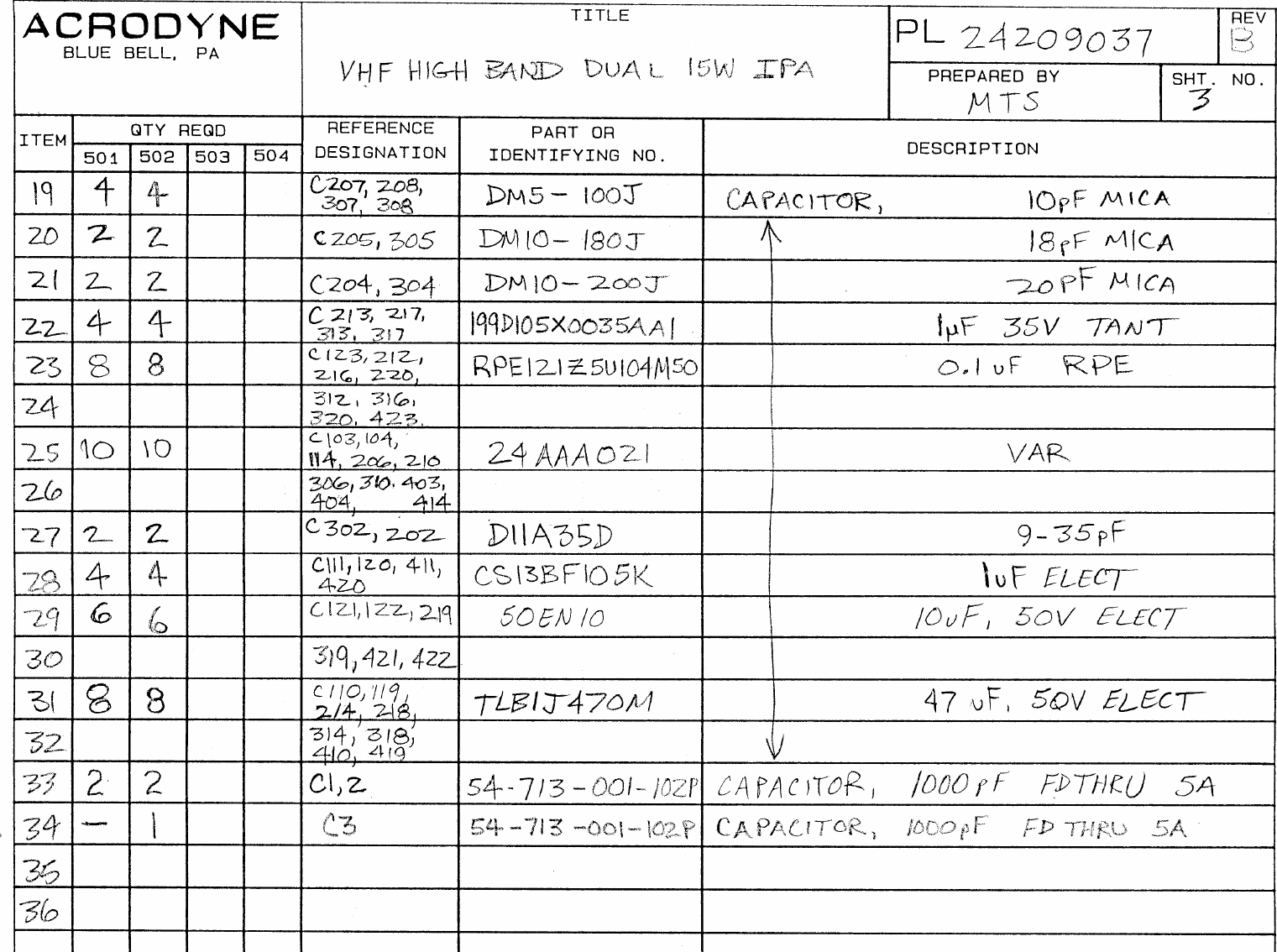
Part 1 Text and Parts Lists