Acrodyne 22802332 Broadcast Television Transmitter User Manual TRH1KE 3
Acrodyne Industries, Inc. Broadcast Television Transmitter TRH1KE 3
Acrodyne >
Contents
- 1. Part 1 Text and Parts Lists
- 2. Part 2 Schematics and drawings
Part 1 Text and Parts Lists

TRH1KE_3.doc3.28-Jul-99 i
NOTICE
EQUIPMENT LOST OR DAMAGED IN
TRANSIT
When delivering the equipment to you , the driver or
carrier’s agent will present a receipt for your
signature. Do not sign it until you have (a) inspected
the containers for visible signs of damage and (b)
counted the containers and compared with the amount
shown on the shipping papers. If a shortage or
evidence of damage is noted , insist that notation to
that effect be made on the shipping papers before you
sign them.
After receiving the equipment, unpack it and inspect
thoroughly for concealed damage. If concealed
damage is discovered, immediately notify the carrier,
confirming the notification in writing, and secure an
inspection report. Loss or damage in transit is not
covered by Acrodyne. You must file a claim with the
carrier.
All shortages should be reported to:
ACRODYNE INDUSTRIES, INC.
FIELD SERVICE DEPARTMENT
516 TOWNSHIP LINE ROAD
BLUE BELL, PA 19422 USA
TELEPHONE: (215) 542-7000 OR (800) 523-
2596 (OUTSIDE PA)
FAX NO: (215) 540-5837
E-MAIL: ACROINFO@ACRODYNE.COM
INTERNET: ACRODYNE.COM
SAFETY CONSIDERATIONS
Through out Acrodyne instruction manuals the
following terms designate hazards and special
considerations for proper equipment operation.
WARNING
“WARNING” designates a personnel hazard.
Personal injury may result if good operating practice
and the operators manual are not followed.
CAUTION
“CAUTION” designates a hazard which may damage
or destroy the equipment if good operating practice
and the operators manual are not followed.
NOTE
“NOTE” designates instructions which must be
followed to assure operation as specified
WARNING
Hazardous and lethal voltages are present in this
equipment when connected to AC mains voltages.
Do not attempt any adjustments of this equipment that
requires opening covers or panels without first
removing and locking-out AC mains feeds and using
the grounding sticks provided to discharge the power
supply capacitors.
Never disable interlocks for access panels to areas
containing high voltage. The interlocks are there for
your protection.
Do not perform maintenance or service this
equipment when alone. Observe safety procedures at
all times. Read this equipment manual before
attempting operation of this equipment; know your
equipment.
High pressure blowers may be used in this equipment.
Such blowers produce high sound levels. Long term
exposure to these levels may adversely affect hearing.
Always use hearing protection when working around
operating equipment.
Keep all blowers intake guards, filters, etc. in place.
The rotating impeller will suck in lose clothing, long
hair with potentially fatal results.
The transmitter produces RF radiation that may be
harmful. Ensure that all RF connections within the
transmitter and from the transmitter RF output
through externally connected coaxial components to
the antenna or terminating load are fully tightened.
WARNING
The RF power transistors used in this transmitter may
contain beryllium oxide, which is hazardous if its dust
is inhaled, or is contacted by broken skin. Use
caution when handling RF power transistors. If
damage should occur to a transistor the part should be
handled with gloves and sealed in a plastic bag.
FAULT PROTECTION CIRCUITS
The equipment described in this manual contains
protective circuits and mechanisms which provide
fault protection to minimize the effects of external
and internal fault conditions. Proper maintenance and
operational verification of these circuits and
mechanism must be performed routinely to assure that
the fault protection circuits are functioning properly.
EQUIPMENT REPAIR
After the equipment warranty expires, return of the
unit to the factory for repair is recommended. If you
wish to return an Acrodyne product for repair, call the
Customer Service Department to notify them of your
intent. Please include a written description of the
problem you have encountered, the model number

TRH1KE_3.doc3.28-Jul-99 ii
and the serial number with the unit you return. If you
wish to attempt to repair the unit yourself, note that
repairs should be made only by those with experience
on transistor circuits and printed circuitry. Incorrect
procedures can damage a unit beyond repair. Order
replacement semiconductors from Acrodyne.
Standard passive components may be purchased from
electronic supply houses. Refer to the parts list
sections for parts information.
NOTE
Acrodyne reserves the right to change specifications,
components or design from that stated herein or to
discontinue models at any time without notice and
without incurring obligation.

TRH1KE_3.doc3.28-Jul-99 1
1.0 GENERAL INFORMATION
1.1 INTRODUCTION
The Acrodyne TRH/1KE Television Transmitter
broadcasts C3F visual and F3E aural emissions on
any single television channel between 174 and 230
MHz at a transmitter output level of 1 kilowatt peak
of sync visual and one hundred watts average aural
power. The units uses intermediate frequency (IF)
modulation and combined visual and aural carrier
amplification throughout.
The entire transmitter is contained within a single
19 inch wide cabinet.
1.2 DESCRIPTION
Refer to the block diagram included with the
drawing package.
The TRH/1KE may be broken down into three
major sections. They are 1) Exciter, 2) Intermediate
Power Amplifier (IPA) and 3) Final Power Amplifier
(PA) and associated control circuits and power
supplies.
The transmitter’s program video signal path
begins with the Video Sync Automatic Gain Control
(AGC) printed circuit board within the Video
Processor Chassis. Video AGC is used to stabilize
the program video signal sync region against
variations in the signal supplied to the transmitter.
The Video AGC output signal is then connected to
the Video Corrector printed circuit board within the
processor chassis. The Video Corrector is used to
provide adjustment of the transmitter differential
gain/differential phase characteristics and for sync
pulse amplitude adjustment.
The processed video signal from the Video
Processor Chassis is routed to the Exciter Chassis and
the modulator circuit where it amplitude modulates
the visual intermediate frequency carrier operating at
45.75 MHz CCIR M/38.9 MHz CCIR G. The
modulated carrier is then passed through a SAW
(Surface Acoustic Wave) filter with group delay
correction to provide the proper lower sideband and
group delay performance.
The transmitter’s program aural signal path
begins directly with the Exciter Chassis and the aural
modulator circuit. Both balanced and unbalanced
aural inputs are provided. These inputs frequency
modulate an aural carrier, operating at 4.5 MHz
CCIR M/5.5 MHz CCIR G, that is then converted to
an IF carrier frequency of 45.75 MHz CCIR M/33.4
MHz CCIR G.
The three signal inputs to the IF Processor
Chassis connect first to the Aural Corrector Board
where signals for correction of vision to sound cross-
modulation are generated. The three signals out of
the Aural Corrector Board are connected to the
Intermodulation (IM)/Incidental Carrier Phase
Modulation (ICPM) Corrector board where they act
to provide correction for inband intermodulation
distortion and incidental carrier phase modulation.
The separate vision and sound IF carrier outputs from
this board are routed to the Visual/Aural Combiner
board and mixed to create a composite IF signal. The
composite IF signal is then connected to the IF
Linearity Corrector circuit board, also within the IF
Processor Chassis. The IF Linearity Corrector board
contains a double break point diode network that is
used to correct primarily for transmitter luminance
(low frequency) non-linearities. The IF Linearity
Corrector output is the output of the IF Processor
Chassis.
The IF Processor Chassis output is connected
back to the Exciter Chassis at the Transmit AGC
input. The Transmit AGC functions to automatically
level the transmitter output power, with the set point
of the Transmit AGC being set by a potentiometer on
the modulator section. The leveled IF signal out of
the Transmit AGC connects to the up converter
section within the Exciter Chassis.
Upconversion of the IF signal to the desired RF
output frequency takes place in the double balanced
mixer in this section, in conjunction with the
upconversion local oscillator, also contained on the
printed circuit board. The RF output of the mixer is
passed through a bandpass filter for removal of
unwanted mixer produces and then amplified to a
nominal ten milliwatt level. The ten milliwatt
amplifier output is the output of the Exciter Chassis.
The nominal ten milliwatt output of the Exciter
Chassis is routed to the One Watt Amplifier Module
mounted on the front of the transmitter between the
output amplifiers. The One Watt Amplifier contains
two RF devices operating in class A mode. The One
Watt Amplifier output connects to the Intermediate
Power Amplifier (IPA) Chassis.
The IPA stage is contained in a single drawer and
contains two parallel sections each of two RF devices
in series. The input signal to the chassis is split into
two and then amplified. The two separate amplifier
output signals are each applied to quadrature type
splitters to create four separate output signals each of
about 10 watts in power.
The four IPA output signals are each connected
to separate 350 watt amplifier stages. The 350 watt
amplifier stages are mounted together in pairs to form
a 650 watt amplifier drawer. There are two such
drawers used in this TRH/1KE transmitter. Each 350
watt amplifier section contains a single device stage
driving a second stage of two devices in parallel. The

TRH1KE_3.doc3.28-Jul-99 2
output signals from each of the 350 watt amplifiers in
a 650 Watt Amplifier Drawer are combined using a
quadrature type power combiner mounted separate
from the drawer. The output signals from the two
2x350 watt combiners further combined using another
quadrature combiner.
The resulting 1100 watt output signal is routed
through a circulator for protection of the transmitter
against high VSWR. The circulator output is
connected through a directional coupler section for
monitoring of the RF output power. The coupler
output signal is routed out of the cabinet and through
a high power band pass filter for removal of the out of
band intermodulation products generated by the
transmitter.

TRH1KE_3.doc3.28-Jul-99 3
1.3 SPECIFICATIONS
OVERALL VISUAL
PERFORMANCE SPECIFICATIONS
Peak Visual Power 1000 watts
Operating Channel Any single channel between 174 and 230 MHz
Output Impedance 50 ohm
Output Connector EIA 1-5/8” flange, male
Video Input Impedance 75 ohm
Video Input Level 1.0V p-p ±6dB
Visual Sideband Response
CCIR M -3.58 MHz: -42dB
-1.25 MHz and below: -20dB
-0.75 MHz to +4.18 MHz: +0.5,-1.0dB
+4.75 MHz and higher: -30dB
CCIR B -4.43 MHz: -42dB
-1.25 MHz and below: -20dB
-0.75 MHz to +4.8 MHz: +0.5,-1.0dB
+5.0 MHz: +0, -2.0dB
+5.5 MHz and higher: -20dB
Visual Carrier Stability ± 350 Hz per month aging, ± 350 Hz from 0 to +45o C temperature
Differential Gain 5% maximum
Differential Phase 3° maximum
Low Frequency Linearity 5%
2T K Factor 2%
12.5 T K Factor 5%
Incidental Phase Modulation ±3° maximum, blanking to white
Modulation Capability 3%
AM Noise (RMS) -52dB
Amplitude Variation Over One Picture
Frame 3%
Output Regulation 3%
Envelope Delay vs. Frequency Per CCIR format specifications
Inband Intermodulation Distortion -54B
Harmonic -60dB
Spurious Emissions -60dB
OVERALL AURAL PERFORMANCE SPECIFICATIONS
Average Aural Power 100 watts, maximum
Audio Input:
Impedance 600 ohm
Level +10dBm ±6dB
Amplitude vs. Frequency Response 1dB
Audio Frequency Distortion 1% maximum
FM Noise -50dB relative to 100% deviation (± 25kHz deviation CCIR M,
± 50kHz deviation CCIR G)
Carrier Stability ±100 Hz, ref. to visual carrier

TRH1KE_3.doc3.28-Jul-99 4
ELECTRICAL SPECIFICATIONS
Power Line, AC Voltage As ordered. Available as 230VAC, 2W; 230/115VAC 3W; or
208Y/120VAC, 4W, 3 phase or 380Y/220VAC, 4W, 3 phase
Voltage Tolerance ±10%
Frequency 47-63 Hz
Service Ampacity 30 ampere minimum for 230VAC single phase service
25 ampere minimum for 208VAC three phase service
15 ampere minimum for 380VAC three phase service.
MECHANCIAL SPECIFICATIONS
Size 22 x 67 x 32” (WxHxD)
Weight 575 lbs., ±10%
ENVIRONMENT SPECIFICATIONS
Ambient Temperature 0 to +45o C
Heat Load 10 kBTU/hr with cabinet exhausted to transmitter room. 3 kBTU/hr
with cabinet exhaust ducted from transmitter room.
MODULE SPECIFICATIONS
10mW AMPLIFIER/MIXER SPECIFICATIONS
Frequency Range, RF Output 174 to 230 MHz
Conversion Gain IF Input to On Channel
Output 27dB minimum
Gain Variation Over Any One
6 or 7 MHz Channel 0.1dB maximum
Input Voltage +12 VDC
Input Current 500mA nominal
VSWR (50 Ohm) 1.5:1 maximum
Output VSWR (50 Ohm) 2.0:1 maximum
Local Oscillator Input +7dBm minimum
ONE WATT AMPLIFIER SPECIFICATIONS
Frequency Range 174 to 230 MHz
Gain 17dBm minimum
Gain Variation Over Any
6 or 7 MHz Channel 0.5dB maximum
Input Voltage +22 VDC
Input Current 1.0A nominal
Input VSWR (50 Ohm) 2.0:1 maximum
Output VSWR (50 Ohm) 2.0:1 maximum
LOCAL OSCILLATOR SPECIFICATIONS
Method Phase Locked Voltage Controlled Oscillator
Reference Frequency 8 MHz
Frequency Range 210 to 260 MHz
Input Voltage +12 VDC
Input Current 400 mA
Output Nominally +10dBm

TRH1KE_3.doc3.28-Jul-99 5
INTERMEDIATE POWER
AMPLIFIER SPECIFICATIONS
Frequency Range 174 to 230 MHz, any single channel
Gain 21dB typical
Input Voltage 27 VDC
Input Current 15 amperes
650W POWER AMPLIFIER
MODULE SPECIFICATIONS
Frequency Range 174 to 230 MHz, any single channel
Gain 18dB typical
Input Voltage 27 VDC
Input Current, Each Device 6A class A drive (constant)
6A class AB output stage,
black picture, 10% aural

TRH1KE_3.doc3.28-Jul-99 6
1.4 ILLUSTRATION LIST
The illustration list included with this manual
lists all assembly drawings (layout pictorials) and
circuits schematics for all portions of this transmitter.
It may be useful to know that all of the drawings
in this manual are numbered with an eight digit
drawing number. For documentation control
purposes the first digit is always a 2. The second
digit is assigned according to the original drawing
size where:
Second Digit Document Size
1A, 8 1/2 X 11
2B, 11 X 17
3C, 17 X 22
4D, 22 X 28
Note that even though a drawing in the manual
may be 8 1/2 x 11, it can still have a B size
designation because the original version of the
drawing was done as a B size document. The third
digit is for classifying the drawing as to type, where:
Third digit Assignment
1MASTER ASSEMBLY
2SUB ASSEMBLY
5SCHEMATIC OR BLOCK
DIAGRAM
0MANUAL ONLY INFORMATION
The last 5 digits are chosen in sequence from
00001 to 99999, where 00001 is the first drawing
made, 00002 is the second drawing, etc.

TRH1KE_3.doc3.28-Jul-99 7
2.0 INSTALLATION
2.1 INTRODUCTION
The installation of the TRH/1KE requires basic
electrical knowledge and use of common hand tools.
The transmission line components require only the
careful handling that should be given such items. The
following instructions and suggestions are not meant
to be the only way for a correct installation.
However, any variation from recommended
installation procedures given may be in violation of
Acrodyne warranties. Please consult the Factory
Field Service Department before attempting any
alternate methods of installation.
ACRODYNE INDUSTRIES, INC.
FIELD SERVICE DEPARTMENT
516 TOWNSHIP LINE ROAD
BLUE BELL, PA 19422 USA
TELEPHONE: (215) 542-7000 OR (800) 523-
2596 (OUTSIDE PA)
FAX NO: (215) 540-5837
E-MAIL: ACROINFO@ACRODYNE.COM
INTERNET: ACRODYNE.COM
2.2 UNPACKING AND INSPECTION
Mechanical assistance will be needed to move
the unit due to its weight. Due care must be used to
unpack the unit. Do not use blows with a hammer or
power chisel to unpack the unit. A general purpose
wrecking bar and claw hammer is all that is needed to
disassemble the shipping container.
WARNING
USE CARE IN CUTTING THROUGH
RESTRAINING STRAPS USED TO SECURE
THE EQUIPMENT. THESE STRAPS ARE
UNDER HIGH TENSION AND THEIR
RELEASE CAN BE EXPLOSIVE IN NATURE.
DO NOT STAND DIRECTLY IN FRONT OF
ANY STRAPPING WHILE CUTTING
THROUGH IT.
After the equipment has been unpacked, it should
be inspected for any damage that may have resulted
during shipment.
Inspection Checklist
1. Front of Transmitter: Check for warpage, dents,
etc. All panels should have all screws in place.
Doors should unlock and open freely.
2. Meters, lenses, bulbs, etc: Inspect all meters for
cracks and damage and check all lenses and
LEDs for damage.
3. Rear of Transmitter: Check rear door lock for
operation. Open rear door and look for loose
hardware or components on the floor of the
cabinet.
4. Top of Transmitter: Check the RF output flange
for damage. Check electrical entrance point and
RF/video input BNC connector and audio input
terminal barrier (where used).
5. Inside of Transmitter: Check for following
items:
650 watt amplifier cooling blowers, impeller
should rotate freely by hand.
All wiring harnesses for security.
If the unit is damaged electrically or
mechanically, notify the carrier and
ACRODYNE INDUSTRIES, INC. immediately.
NOTE
SOME ASSEMBLIES MAY HAVE PACKING
MATERIAL USED TO MECHANICALLY
STABILIZE THEM DURING SHIPMENT. ANY
PACKING MATERIAL USED IS LABELED AS
SUCH AND SHOULD BE REMOVED AT THIS
TIME.
2.3 SITE CONSIDERATIONS
The transmitter site/location choice is of utmost
importance. To ensure long life of your transmitter,
the following list is an important checklist of
concerns that must be known and continuously
monitored before, during and after installation and
throughout the life of the transmitter. Abuse of any
sophisticated electronic equipment can only lead to
short operation life and/or expensive repairs. Be
cautious of the following:
1. Maintain a clean and dry building/enclosure.
2. Ensure a stable electrical supply. Provide a
secure and stable earth ground for the transmitter
and any AC transformer used.
3. Secure the transmitter space to prevent
unauthorized entry.
4. Avoid temperature extremes. A maximum room
ambient of 25°C is recommended. It is
recommended that the cabinet top exhaust be
ducted outside. Back pressure presented to the
cabinet exhaust by the external duct work must
be kept to a minimum. It is preferable to use an
assist fan in the exhaust duct work to provide a
negative pressure to the cabinet exhaust. If this
is done it is very important to provide adequate
room intake air. The cabinet top exhausted air
volume is approximately 900 cubic feet per

TRH1KE_3.doc3.28-Jul-99 8
minute (CFM). The building intake must allow
for this plus some margin. In addition the air
intake must be provided with adequate filtering.
The area of the intakes should be large enough to
keep the intake air velocity below 300 feet / 100
meters per minute. This will allow the intake
dirt/dust filters to capture the maximum amount
of dirt possible. With the exhaust volume at 900
CFM the air intake area should be not smaller
than 3 square feet.
5. The units should sit on a flat, level surface.
Cement floors should be sealed or covered with a
vinyl tile to minimize dust and facilitate cleaning.
2.4 CABINET INSTALLATION
Where possible locate the transmitter cabinet in
close proximity to the intended RF transmission lines
and AC MAINS power disconnect to minimize the
input and output connection runs.
Connect the brass grounding bolt, located at the
rear of the transmitter base, to the site ground system.
This is best accomplished with copper strapping or
tinned copper braid.
WARNING
POOR GROUNDING OF THE TRANSMITTER
MAY CAUSE SEVERE INJURY OR DEATH IF
A FAULT SHOULD OCCUR.
When the transmitter has been shipped with the
650 Watt Amplifier Drawers removed from the
transmitter cabinet, reinstallation of the modules
should be done following a few simple
recommendations.
1. Though it is possible for one person to handle
and install a drawer it is recommended that two
persons perform the procedure. Dropping a
drawer would prove to be a very expensive
accident.
Each drawer has a unique position in the
transmitter and is identified by a number on both
the drawer and that position within the cabinet.
Make certain that the drawers are put into the
proper slot corresponding to their number labels.
2. One of the pair of cabinet mounted slides (one
pair for each drawer) should be adjusted to its
fully extended and locked position, and the
drawer slide has been mated properly, the other
half of the cabinet pair can be pulled forward and
attached to the drawer.
3. The spring metal tabs on either side of the slides
are pushed in to unlock the slides and allow the
drawer to be pushed in.
4. There are seven connections that need to be
made to each drawer, four coaxial cable
connections and three harness cable connections.
Each drawer is to be connected to a distinct cable
group that branches from the cabinet wire
harness, at the top of the cabinet. The left most
drawer to the left most cable group etc.
The N type RF output connections should be
made finger tight, while the SMA type RF input
connections should be made wrench snug. A 5/16
inch wrench is used.
The all black control cable connector is keyed
such that improper orientation is impossible. The
knurled locking ring should be rotated fully to lock
the mated connector in place.
Special attention should be given to properly
connecting the two high current connectors for the
module. This connector is blue and black. The body
of the high current connector is keyed to ensure
proper mating. The harness cable end plug is inserted
in the drawer mounted jack and twisted clockwise to
lock it in place. The silver locking tab should snap
into place to lock the entire connector. To verify this
connector is properly in place, grasps the outer
connector shell and tug outward. A properly made
connection will remain together.
2.5 EXTERNAL CONNECTIONS
2.5.1 AC MAINS
CAUTION
VERIFY THAT THE AC MAINS CONNECTED
TO THE TRANSMITTER IS THE SAME AS
INDICATED ON THE LABELING ATTACHED
TO THE CABINET TOP JUNCTION BOX.
1. The transmitter AC MAINS input connection
point is within the junction box located on the
transmitter cabinet top. Conduit is to be
mechanically fastened to the outside of the
cabinet top junction box.
2. Refer to the Electrical Specifications in section
1.3 for the recommended service ampacity for
the mains configuration of the transmitter
delivered. For a single phase service configured
transmitter, the line-to-neutral voltages must both
measure between 107 and 132 VAC. For a three
phase service configured transmitter the phase-
to-phase voltages must measure within 5% of
each other.
For three phase configured transmitters,
there is a three phase power monitor that
monitors the presence, and absolute and relative
voltage levels. A loss of phase, a low overall
voltage, or a phase-phase voltage imbalance will
trip the monitor and keep the transmitter from
turning on. Once the AC MAINS have been

TRH1KE_3.doc3.28-Jul-99 9
connected, apply mains power and verify that the
TRIPPED indicator on the phase monitor, visible
through the front circuit breaker panel, is not on.
If the TRIPPED indicator is on, verify that the
AC MAINS power is present at the øA, øB, øC,
terminal inputs. If the voltage is not there
investigate AC MAINS wiring to the monitor and
take corrective action to connect the AC
properly. If the voltage is present the TRIPPED
indicator means that the proper A to B to C phase
rotation is disturbed. Disconnect and swap any
two input AC MAINS lines and recheck the
monitor. Repeat as necessary to cause the
TRIPPED indicator to be off.
3. Connect the brass grounding bolt located at the
rear of the transmitter base to the site grounding
system. This is best accomplished with copper
strapping or tinned copper braid.
WARNING
POOR GROUNDING OF THE TRANSMITTER
MAY CAUSE SEVERE INJURY OR DEATH IF
A FAULT SHOULD OCCUR.
2.5.2 OUTPUT TRANSMISSION LINE AND
ANTENNA
Refer to the application drawing supplied.
A bandpass filter is supplied that must be
mounted external to the transmitter cabinet.
Dependent on optional equipment purchased
directional couplers, patch panels and dummy loads
may also need to be installed. Due to variations in
installation, elbow connections connecting coaxial
lines, etc. are not normally provided, unless
specifically ordered.
The installation may vary from that indicated in
the application drawing, through it is highly
recommended that the bandpass filter and directional
coupler be placed immediately at the cabinet output.
The actual lengths of inter-connecting pieces is left
up to the installer's discretion.
CAUTION
HANDLE ALL COAXIAL COMPONENTS
WITH CARE. ANY DAMAGE WILL
ADVERSELY AFFECT THE TRANSMITTED
SIGNAL. ALL COAXIAL COMPONENTS
SHOULD BE SUPPORTED AT THE FLANGES.
SECTIONS LONGER THEN TEN FEET
REQUIRE ADDITIONAL MID SUPPORT. ALL
FLANGES SHOULD HAVE EVERY BOLT
HOLE SECURED WITH THE PROPER
HARDWARE. COAXIAL COMPONENTS
MUST NOT BE USED TO SUPPORT OTHER
STRUCTURES.
Bandpass Filter
An external bandpass filter is supplied. It must
be mounted to minimize any stress placed on the
input and output connectors. It must not be hung by
the connectors. Use the mounting flanges that are a
part of the filter body.
A six foot length of Heliax cable is provided to
connect between the transmitter cabinet type N RF
output and the filter type N input.
Directional Coupler (Optional)
If an external directional coupler is supplied it
should be mounted directly on the transmitter filter 1-
5/8” flange RF output. The coupler monitors the
forward and reflected output power of the transmitter.
NOTE
ANY DIRECTIONAL COUPLER SECTIONS
MUST BE INSTALLED WITH THEIR "RF
INPUT" DESIGNATED END POINTING
TOWARDS THE TRANSMITTER RF OUTPUT.
THE "RF OUTPUT" DESIGNATED END MUST
POINT TOWARDS THE ANTENNA.
Patch Panel (Optional)
The patch panels were designed to ease the
changing of the transmission line from the antenna to
the dummy load for maintenance purposes. Included
on the panel(s) is a series of electrical interlocks to
prevent RF transmission into an open transmission
line. If a patch panel has been included as part of this
transmitter, electrical harnesses are provided for this
purpose.
Connect the wire harnesses to the corresponding
terminals on the patch panel(s), and connect the other
end to the transmitter cabinet top terminal barrier
labeled for patch panel usage.
Dummy Load (Optional)
The patch panel may have two additional
positions to accommodate a high power dummy load
and a small signal dummy load.
The high power load may include an RF sample
port and a through-line wattmeter. The small signal
load is used for RF sweeping.
The location of the high power load is not
critical. Consideration should be given to the
electrical needs as well as the generated heat from the
load. Short runs of coaxial cable are desirable. The
dummy load should also be interlocked to prevent
damage, and may be connected through the patch
panel interlock. All the interlock switches should be
serially connected and present a closed circuit in
normal operation. A fault condition should present
an open circuit.

TRH1KE_3.doc3.28-Jul-99 10
Antenna
The antenna and connecting RF transmission
cable return loss must be verified before any RF
signal transmission is attempted. This involves
checking all RF connections and verifying the
"Return Loss" of the transmission line/antenna
combination.
A return loss of 26dB (VSWR = 1.1:1) is usually
required from the visual carrier to +2.75 MHz from
+2.75 MHz to the upper band edge and from visual
carrier to the lower band edge return loss may
degrade to 20dB.
Obtaining a return loss better than 26 dB across
the 6 MHz bandwidth is routinely accomplished. If
there is any uncertainty as to the quality of the
transmission match, the line should not be attached
until such time as the line has been proven to meet
these specifications.
2.5.3 AUDIO/VIDEO INPUTS
The baseband audio and video signals for the
transmitter are to be connected to the transmitter
cabinet top. The program video input to the
transmitter is a BNC connector and is labeled as
PROGRAM VIDEO IN. This is a 75 ohm terminated
connection; there is no loop-through provision.
The input for balanced monaural programming is
the three pin XLR connector on the cabinet top. This
is labeled as BALANCED AUDIO INPUT. Pin
locations two and three are for the signal lines.
Ground/shield is pin one.
Note that if your transmitter has been supplied
with a BTSC stereo generator installed the cabinet
top has been provided with two XLR connectors, one
for each of the left and right channel baseband audio
input signals.
Composite BTSC (stereo aural) fed from an
external stereo generator is to be connected to the
BNC connector labeled UNBALANCED AUDIO IN.
Note that the both the unbalanced and balanced audio
inputs are simultaneously active at the modulator
therefore both audio inputs cannot be driven at the
same time.
Audio pre-emphasis may be selectively applied
to the AUDIO input signal by selecting the proper
position of switch S2 on the Modulator Board. Refer
to the modulator drawings included with the
illustration section for the location of S2.

TRH1KE_3.doc3.28-Jul-99 11
3.0 OPERATION
3.1 INTRODUCTION
The information in this section covers the proper
turn on and turn off procedures to be followed for
proper operation of the transmitter.
3.2 OPERATING PROCEDURES
CAUTION
A KNOWN GOOD 50 OHM TERMINATION
OR ANTENNA SHOULD BE CONNECTED TO
THE EXCITER OUTPUT BEFORE THE TURN
ON SEQUENCE IS BEGUN. ALL
INTERSTAGE CABLING MUST BE IN PLACE
THROUGHOUT THE EXCITER SECTION.
3.2.1 MANUAL TURN ON
1. Set all cabinet circuit breakers to OFF. Set the
Exciter RF Control switch to OFF.
2. Set the transmitter Control Logic drawer Start
Up Control switch to the MANUAL-OFF
position. Set each of the 650 Watt PA Drawer
AMPLIFIER CONTROL switches and the IPA
Chassis AMPLIFIER CONTROL switch to their
center OFF position.
3. Remove the front panel screws holding the
Exciter Chassis in place. Pull the drawer forward
enough to locate the POWER, R84, and GAIN,
R110, adjustment potentiometer access holes.
4. Set the cabinet AC MAINS switch to ON. Check
the +24 volt power supply reading on the Exciter
Chassis. With program or test signal video
connected to the transmitter cabinet top Exciter
VIDEO LOSS LED should be off. If the LED is
on, check for video input, and chassis
interconnect coaxial cables to the Exciter to
obtain a connection of a video signal to the
Exciter and cause the LED to be off.
5. Place the Control Logic START UP CONTROL
switch into the AUTO position. Place the 650
Watt Amplifiers and IPA Chassis AMPLIFIER
CONTROL switches into their AUTO positions.
The 650 Watt PA Drawer current meters should
all indicate at the "Io", quiescent current mark on
the meter scale. If no current meter reading is
evident, check module meter for voltage
indication. 28 VDC should be indicated in each
position. If there is no voltage displayed or it is
low, return both control switches to OFF, switch
OFF the AC MAINS switch and verify the
connections to the 650 Watt PA Drawers from
their cabinet harness connections. The IPA
current meter should indicate 6 amperes.
6. While observing the transmitter Control Logic
multimeter PEAK VIS POWER % position,
place the Exciter RF CONTROL switch into the
AUTO position. Indicated output should
increase to 100%. Adjust the Exciter POWER
control, R84, as necessary set the RF output
power to 100%.
7. Check the AURAL and REFLECTED power
meter positions and compare these readings with
the factory test data supplied with the transmitter.
8. Check the Exciter Chassis AGC voltage meter
reading and compare with the factory test data.
A reading of about 15 (midscale) on the 0 to 30
volt scale is nominal. An indication less than
midscale means there is insufficient IF drive
over-range while an indication greater than
midrange means there is more than the optimal
amount of IF drive over-range. To set the proper
amount of over-range slowly adjust the Exciter
GAIN potentiometer as required to produce a
midscale AGC meter reading.
3.2.2 AUTOMATIC AND REMOTE TURN ON
Master control of the transmitter turn on/turn off
is through the Control Logic printed circuit board.
It is the function of the Control Logic to initiate
the various subsection START UP sequences and to
monitor the subsections for their respective
TRANSMIT READY signals.
For logic control purposes, the transmitter is
broken into amplifier subsections. Each amplifier
subsection is self contained in the sense that it will
monitor itself with respect to proper application of
supply voltages and fault conditions. Fault conditions
within any particular subsection will be attended to by
that subsection. Each subsection is configured to
require the application of a ground to initiate the
START UP sequence within that section. When a
subsection is ready for RF drive (no faults, all
voltages normal, etc), that subsection provides a
ground level signal back to the Control Logic that is,
the subsection, is TRANSMIT READY.
For this transmitter the Intermediate and 650
Watt Power Amplifier drawers are treated as a single
amplifier, even though each has its own Control
Logic PCB.
The transmitter Control Logic gives a START
UP command to both sections as a parallel command.
The Control Logic portions of both of these
amplifiers will then command the power supply to
turn on. As there is a single supply for both these
stages, both stages must be operating properly to turn
on the power supply. A thermal fault in either stage
will cause the power supply to turn off during the
over temperature condition.

TRH1KE_3.doc3.28-Jul-99 12
The Control Logic itself may be instructed to
initiate START UP through a number of ways. The
VIDEO SENSE indicator from the Exciter may be
selected to control when PCB terminals E1 and E2
are connected. This may be overridden by the action
of the contacts of relay K1. K1 is in turn controlled
by remote control systems attached to the transmitter
cabinet REMOTE INTERFACE TB1301 (see manual
section 3.4). The highest priority control for the
transmitter is the START UP CONTROL switch S1.
The AUTO position is selected to permit VIDEO
SENSE or remote control operation. To permit
remote only operation, PCB terminals E2 and E3 are
connected, bypassing the VIDEO SENSE control.
The START UP CONTROL signal supplies a
logic low level at U2 noninverting input, causing U2
output at pin 1, high turning on each of four sections
of a high current transistor array, U1. One or more of
these array sections is used to signal the various
transmitter subsystems to begin their respective start
up cycle.
The "TRANSMIT READY" indicator outputs
from the various transmitter subsystems return to the
Control Logic PCB as logic low levels into U4A and
U4B. These two inputs are combined in U3 to
provide an RF ENABLE control back to the Exciter
Chassis. This RF ENABLE control is active when
low. This also causes the Control Logic front panel
RF ENABLED LED to light.
For automatic operation, transmitter turn on of
all power supplies can be accomplished with the
START UP CONTROL switch on the transmitter
Control Logic drawer if all other control switches are
listed below.
RF Converter RF Control/Auto
IF Amplifier/AGC ON
Transmitter Control Logic Start Up Control/Auto
Amplifier Drawers Amplifier Control/Auto
For remote control of the transmitter,
interconnections are made to the 25 pin D-sub remote
control connectors positioned on the cabinet top.
Refer to the Remote System Connections listing in
the illustration section.
3.2.3 EQUIPMENT TURN OFF
The transmitter may be turned off by removal of
the input video, if all CONTROL LOGIC control
switches are in their AUTO position. Alternately, the
START UP CONTROL switch may be placed into
the MANUAL OFF position.
The remote control turn off feature is only
functional with the START UP CONTROL switch in
the AUTO position, as the remote turn off circuit is in
series with the AUTO circuit control line. This
allows manual control of the transmitter to be
exercised regardless of remote control system status.

TRH1KE_3.doc3.28-Jul-99 13
5.0 MAINTENANCE
5.1 INTRODUCTION
Proper procedures for maintaining the transmitter
are provided to ensure continued safe operation of the
equipment.
5.2 RF POWER METER CALIBRATION AND
AGC SET POINT ADJUST
Power calibration of the transmitter should be
performed on a regular basis to ensure proper
operation both under regulatory agency rules as well
as transmitter specifications. It is recommended that
a wattmeter line section be installed at the time of
equipment installation to be used as a backup power
indicator as well as a reference for power calibration.
1. The transmitter should be connected to a
substantially resistive load/termination, rated to
handle on an average basis, the full peak power
rating of the transmitter. In both cases, any
filters supplied with the transmitter must be
included in the output circuit of the amplifier
before the measurement point. The wrap around
AGC for the transmitter must be defeated by
manually adjusting the Exciter board power
adjust potentiometer R84 clockwise, until the
yellow status LED on the Exciter board goes on
or the transmitter power reaches 110%. Use gain
potentiometer R110 to reset transmitter output
power to the desired level. Remove the aural
carrier by switching the Aural Corrector Board
AURAL CARRIER switch to the OFF position.
The IF Processor Drawer must be pulled fully
forward to access this switch.
2. If an Acrodyne supplied coupler section is to be
used for power calibration, a microwave power
meter will be necessary. The coupling sections
are factory calibrated against known standards
and the specific coupling values are dependent
on transmitter output power.
3. Using a directional wattmeter, any plug-in
element selected should provide a maximum
deflection of the meter to minimize meter
movement errors. The visual only power must be
measured under the specific conditions of:
a. Visual carrier only, aural carrier off. Turn
off the aural carrier using the Exciter Chassis
front panel Aural Carrier ON/OFF switch.
b. Sync and blanking level video only (black
picture) with a sync pulse amplitude of .287
volts CCIR M (40 IRE)/.30 volts CCIR B/G.
4. The transmitter peak visual power rating is
multiplied by the conversion factor of 0.595 for
CCIR M and .57 for CCIR B/G to obtain the
average reading that will be displayed on the
wattmeter.
ex: this 1,000W (peak of sync) transmitter will
display an average power of (1,000W x
0.595) or 595 watts average power under the
specific conditions noted when transmitting
a CCIR M standard signal. It must be
remembered that it is the average power that
will be displayed.
5. Set the proper visual power level using the
Exciter gain pot R110. With the visual power
level now established re-apply the aural carrier
by switching the IF Processor Drawer AURAL
CARRIER switch to the ON position. On the
Aural Corrector Board adjust the AURAL
POWER LEVEL potentiometer R81 clockwise
until a minus 8 dB aural to visual carrier ratio is
achieved as indicated on a spectrum analyzer
display. Now adjust the AURAL OVERRANGE
pot R111 until the aural carrier level is restored
to -10 dB. The Aural Corrector Board yellow
LED should be on as seen through the AURAL
CARRIER ON-OFF switch access hole.
6. When both levels have been set, the transmitter
RF POWER MONITOR ASSEMBLY, meter
drive levels can be adjusted to provide accurate
power meter indications. There is a single input
level adjust to each of the three metered
functions. Refer to assembly drawing 22207217
and associated board schematic for adjustment
location.
The PEAK VISUAL FORWARD POWER
display on the CONTROL LOGIC chassis should
be monitored while adjusting R24 on the power
monitor board.
The AVERAGE AURAL FORWARD POWER
display on the CONTROL LOGIC chassis should
be monitored while adjusting R2 on the power
monitor board.
The AGC SAMPLE output of the power monitor
board at TB2-11 should be monitored with a
DVM while adjusting R46 on the power monitor
board. R18 should be adjusted to achieve a 2.5
VDC AGC SAMPLE reading, at the power
monitor TB2-11.
7. On the Aural Corrector Board adjust the AURAL
OVERRANGE pot R111 until the aural carrier
level is returned to minus 8 dB. Now adjust the
AURAL POWER LEVEL potentiometer R81
until a minus 10 dB aural to visual carrier ratio is
achieved as indicated on a spectrum analyzer
display. The Aural Corrector Board green LED
should be on as seen through the AURAL
CARRIER ON-OFF switch access hole.

TRH1KE_3.doc3.28-Jul-99 14
NOTE
THE SYSTEM RF METERS FOR AURAL AND
VISUAL POWER ARE NOW PROPERLY
ADJUSTED. THE AUTOMATIC GAIN
CONTROL FOR THE AURAL CARRIER IS
CALIBRATED TO BOTH THE VISUAL AND
AURAL METER CALIBRATIONS. DO NOT
RE-ADJUST THE AURAL METER
ADJUSTMENT R6 WITHOUT REPEATING
STEPS 4THROUGH 6. THE AURAL CARRIER
RATIO MAY BE ADJUSTED WITH R81 ON
THE AURAL CORRECTOR BOARD IF A
CHANGE IN CARRIER LEVEL IS DESIRED.
8. The reflected (or reverse) power meter can now
be calibrated. First, adjust output power
downward using the Exciter GAIN control R110
to achieve a 10% power indication from the
PEAK VISUAL FORWARD POWER meter
position, then reverse the forward and reflected
detected RF signals at the RF Power Monitor
Assembly J21 and J2 connectors. . The forward
coupler port is now attached to the reflected
power input port, J72, of the power monitor
board. The REVERSE POWER display on the
CONTROL LOGIC chassis should be monitored
adjusting on the power monitor board. Set for a
10% reverse power indication. Note that the
reverse power meter scale is expanded for
increased resolution.
9. Return the detector diode assemblies to their
original position, and readjust R110 for an output
power indication of 110%. Reset output power
to 100% meter indication using POWER control
R84.
5.3 VIDEO AND IF PROCESSOR
ADJUSTMENTS
Video Sync AGC Adjustments
The Video Sync AGC board needs no
adjustments in normal operation. Out of service
checks of the operation of the board would be:
1. Verify that the output video blanking level is at 0
volts DC. Use potentiometer R18 to adjust as
required.
2. Verify that the output video amplitude is one volt
peak to peak for an input signal of one volt peak
to peak. Adjust potentiometer R14 to adjust
output level as necessary.
3. Verify that the video is as flat as possible through
the board using a multiburst video test signal or a
video sideband signal generator. Adjust
capacitor C9 to optimize flatness.
Video Corrector Adjustments
Refer to drawing 22708899.
The Video Corrector has been adjusted at the
factory to provide optimum performance at the output
power level specified for the transmitter. In normal
operation, there should be no need to make gross
adjustments to this circuit. If the output power level
of the transmitter is changed, it will be necessary to
verify the performance of the differential phase and
gain parameters and adjust the Video Corrector to
optimize those parameters. Under no circumstances
should the Video Corrector circuits be adjusted
without the proper monitoring equipment. This
includes a good quality TV demodulator, video
waveform monitor, and vectorscope. Do not adjust
any corrector controls unless you have the proper
equipment to monitor the effects of the control
adjustment.
When making adjustments the differential gain
should be corrected first, followed by the differential
phase. This procedure will produce the best results
with the fewest readjustments.
There are four separate, independent differential
gain correction circuits. The circuits associated with
diodes CR8 and CR9 will provide a positive
differential gain correction while those associated
with diodes CR10 and CR11 will provide a negative
differential gain correction. Potentiometers R67,
R72, R77 and R82 control the amount of differential
gain slope correction each circuit will provide.
Potentiometers R69, R74, R79 and R84 control
the voltage level, with respect to the luminance level,
at which the differential gain correction will occur.
To reduce the differential gain correction, the
potentiometers should adjusted CCW.
Trimmer capacitor C9 adjusts the total chroma
gain curve to increase or decrease the overall chroma
gain. Adjustments should be made while watching
the demodulated transmitter output on the differential
gain display of a vectorscope.
There are four separate independent differential
phase correction circuits. The circuits associated with
diodes CR4 and CR5 will provide a positive
differential phase correction while those associated
with diodes CR6 and CR7 will provide a negative
differential phase correction. Potentiometers R47,
R52, R57 and R62 control the amount of differential
phase slope correction each circuit will provide.
Potentiometers R49, R54, R59 and R64 control
the voltage level, with respect to the luminance level,
at which the differential phase correction will occur.
Adjustments should be made while watching the
demodulated transmitter output on the differential
phase display on a vectorscope. To reduce the

TRH1KE_3.doc3.28-Jul-99 15
differential phase correction, the potentiometers
should be adjusted CCW.
Video gain is adjusted with potentiometer R21.
The video gain should be adjusted to produce a 1.0 V
peak-to-peak composite amplitude at the switched
output which should be terminated in 75 ohms.
The sync amplitude may be adjusted by
potentiometer R40. This control should be set
maximum CCW when additional sync amplitude is
not required at the transmitter output.
The sync separator circuit contains two trimmer
capacitors, C2 and C6. Trimmer capacitor C2 in
series with inductor L1, form a chroma trap.
Trimmer C2 should be adjusted to eliminate the
chroma on the video signal as seen on the emitter of
Q2. Trimmer capacitor C6 in parallel with inductor
L2 forms a high impedance network at the burst
frequency to prevent the burst clamp pulse from
distorting the burst. Trimmer C6 should be adjusted
so that the burst is not affected when observing the
output of the unit. Care should be taken when making
this adjustment to ensure that the clamp pulse rise and
fall times do not cause spikes before and after the
burst. Switch S1 on the corrector circuit board
controls the bypass function.
Aural Corrector Adjustments
Refer to 21712091.
Note that only the potentiometers and switches
are adjusted here. (The trimmer capacitors are
adjusted when the board is aligned).
The adjustments on this board are independent;
they should not affect any other transmitter
adjustment. However, it should be noted that part of
what this board corrects for is caused by the IF
Corrector. Also, a badly misadjusted Aural Corrector
board could cause undesired FM, cross-mod AM, or
improper aural carrier level ratio.
The adjustments are done to minimize the
amplitude modulation components on the aural
carrier as displayed on a spectrum analyzer. The
analyzer should be set as follows: resolution band
width of 3 kHz, 200 kHz scan. Adjust the corrector
to minimize the peak modulation with all program
audio off. It is also possible to look at a demodulator
audio output in the frequency domain using a low
frequency capable spectrum analyzer. Cross
modulation will appear as a 15.7 kHz component and
multiple harmonics thereof. They will all go down as
the correction is performed. The lowest component,
at 15.7 kHz, is critical and should be minimized.
Adjust the AMPLITUDE 1, SHAPE 1 and
PHASE 1 controls as one group and AMPLITUDE 2,
SHAPE 2 and PHASE 2 controls as a second group.
If the POLARITY switch is in center position
there will be no correction. In general, switching the
POLARITY to one side will reduce the cross mod
and switching it to the other side will make it worse.
In this case, adjust PHASE for lowest cross mod, and
then fine tune AMPLITUDE. If there doesn't seem to
be any change from center to either side, the
AMPLITUDE needs to be increased. If both side
POLARITY positions make the cross mod worse than
the center, even when a different PHASE setting is
tried, the AMPLITUDE may have to be reduced.
An iterative process is usually required, working
between the controls of one group and then the
controls of the other. While reducing the cross
modulation as evidenced by amplitude modulation on
the aural carrier pay attention to the sync pulse and
any ringing on the leading or trailing edges. A
properly adjusted Aural Corrector will minimize
cross modulation as well as sync ringing.
IM Corrector Adjustment
Refer to drawing 22310680.
The potentiometers and switches are all system
level controls. The trimmer capacitors, on the other
hand, are adjusted when the board is aligned and
should not be touched in the system. The drawing
22310680 shows the position of, and labels, the
system level controls. The on/off, amplitude, phase
and polarity controls are grouped into the categories
Static, APL, and Master (affecting both Static and
APL components). The terms STatic, PHase, Right,
Left are abbreviated to ST, PH, R, L to save space in
some cases.
In general, each polarity switch (R, L, R ST, L
ST) has a PHase control (R PH, L PH, R ST PH, L
ST PH) and an amplitude control (R, L, R ST, L ST)
associated with it. When the master polarity switches
(R, L) are in center position, the IM corrector
operation is disabled. When the Static polarity
switches (R ST, L ST) are in center-off, the Static
component is disabled. During system adjustment, a
polarity test should be done first. When the two “on”
positions of a polarity switch are tried, there are three
possible outcomes:
1. Little or no change is observed in the IM in
any of the three polarity switch positions.
2. Both “on” positions make the IM worse than
the “off” position.
3. One “on” makes the IM better than the “off”
(the other “on” makes it worse).
In case 1 above, the appropriate amplitude
control (potentiometers R, L, R ST, L ST) should be
turned up (clockwise) and the polarity test repeated.
In case 2 above, the appropriate amplitude control
should be turned down and the polarity test repeated.

TRH1KE_3.doc3.28-Jul-99 16
In case 3 above, the appropriate PHase control (R
PH, L PH, R ST PH, L ST PH) should be adjusted to
null the IM. A further null should be tried by slightly
adjusting the amplitude control also.
When the board has been adjusted before, but a
slight “touch-up” is needed, it is recommended that
the controls in the “Master” section of the drawing
22310680 be used.
When the board is being adjusted for the first
time, the recommended procedure involves using a
video source capable of a fixed amount of chroma on
a variable APL flat field. This can be done from a
Tektronix 147A with 4.43 MHz chroma carrier (on
back) looped to the auxiliary input on the front, and
using the variable pedestal control on front. A
Tektronix 1405 sideband can be used if an external
+5 dBm fixed frequency is connected into the 1405’s
LO input. The frequency is arbitrary but it should be
within the 2.09 to 3.1 GHz shown on the back of the
instrument. On the 1405, turn off the sync and
connect the video output to a counter. Adjust the
1405’s tuning knob to get 4.43 MHz. Then turn the
sync back on and connect the video to the transmitter.
If these are not available, a Tektronix 140 or 146 can
provide two color segments on an adjustable level flat
field.
The adjustment is done by checking
intermodulation products at two APL levels - perhaps
10 APL for black and 80 APL for white. At white,
adjust the controls in the “Static” section (see
22310680) for lowest intermod. At black, adjust the
video amplitude controls as well as the phases R PH,
L PH in the Master section. If the results are not
satisfactory, try a different master amplitude, or a
different setting of the High/Low range switches
labeled R1, R2, L1, L2.
Static ICPM Adjustments
Refer to drawing 22310680.
Start with the ICPM polarity switch in center
position. Make sure the modulation level is correct.
Set up the ICPM display using the quadrature output
of a synchronous demodulator for horizontal input to
the waveform monitor or scope. Turn on the zero
carrier pulse on the demodulator. Use un-modulated
stairstep video. The dots corresponding to each
instantaneous modulation level should form a line. If
this line, when extrapolated straight, already passes
through the zero carrier dot then the Static ICPM
circuit does not need to be used. If not then the other
dots can be shifted relative to the zero carrier dot by
switching the ICPM Polarity to one side and
maneuvering the ICPM amplitude and ICPM PHase.
Actually on most demodulators you will see a
pivoting effect due to the demodulator clamping
holding either the sync dot or the 0 APL dot
(blanking level) in place. When the adjustment is
complete the zero carrier dot should line up (as much
as possible) with the other dots, especially the nearest
ones. Also, the modulation level should not change
as the polarity is switched in and out (disregard the
effect from switching).
IF Linearity Corrector Adjustments
Refer to drawing 22709666.
The corrector is adjusted to primarily affect low
frequency linearity performance and sync level but it
also will alter the differential gain characteristics of
the transmitter. It will be necessary to check the
differential gain characteristics and adjust the Video
Corrector as necessary after making adjustments on
the IF Linearity Corrector.
The Corrector has two identical sets of
adjustments called GAIN and THRESHOLD.
Normally only R2/GAIN and R4/THRESHOLD are
active and used. The GAIN adjustment matches the
saturation curve in the transmitter output while the
THRESHOLD control sets the level of Correction
that is added. The Corrector is not gain compensated
and while the transmitter output will be maintained at
100% by the RF Converters IF Amplifier AGC
circuits, the amount of system gain over-range will
change and may have to be re-adjusted when the
Corrector adjustments are changed.
The GAIN and THRESHOLD adjustments
should initially be considered near the optimum
setting. Counter clockwise rotation of the controls
minimizes the effect of the corrector. The corrector
should be adjusted while monitoring the transmitter
output signal low frequency linearity with a waveform
monitor, and in-band intermodulation products with a
spectrum analyzer capable of 100kHz resolution at 1
MHz/div, using a modulated ramp video format. A
best fit correction setting will maintain 40 IRE units
of sync, 5% or better low frequency linearity, and at
least 52dB in band intermodulation products.
5.4 AMPLIFIER BYPASS OPERATION
In the event that one of the 650 Watt Amplifier
modules experiences a failure and must be taken out
of service, there is a preferred procedure for
operating the transmitter with one amplifier only.
1. Begin by removing the AC mains power to the
cabinet. Next, remove the disabled amplifier
from the cabinet. The spring metal tabs on either
side of the slides are pushed in to unlock the
slides and allow the module to be pulled
completely out.

TRH1KE_3.doc3.28-Jul-99 17
2. There are seven connections that need to be
disconnected from the module, four coaxial cable
connections and three harness cable connections.
3. The circular multi-conductor plug contains the
logic connections to and from the amplifier and
must be bypassed using the mating jack
connector with a single wire in place, that was
supplied with the transmitter. This bypass
connector is keyed and need only be connected
to the cabinet cable end.
4. The output of the hybrid combiner that is
connected to the remaining amplifier must be re-
cabled to the directly to the output directional
coupler. Remove the output cable connection
from the remaining amplifier combiner and
reconnect to the output directional coupler.
5. The Intermediate Power Amplifier RF outputs
that connected into the removed 650 Watt
Amplifier must be terminated into suitable 50
ohm loads. Two terminations are supplied with
the transmitter accessory kit. Connect these to
the two outputs of the IPA Chassis that were
connected to the 650 Watt Amplifier that was
removed.
6. Open the Exciter Drawer to access the RF
POWER adjust potentiometer R84. Adjust the
potentiometer fully counterclockwise. Re-apply
AC mains power to the transmitter. Start the
transmitter and allow. Place the EXCITER RF
CONTROL switch into the AUTO position.
Note that it may take a few seconds for an RF
power indication due to the slow release feature
of the RF CUTOFF circuits. Observe the
CONTROL LOGIC multimeter "PEAK VIS
POWER %" position and adjust the EXCITER
POWER CONTROL to set the RF output power
to 50%. Keep the transmitter at this operating
power until a repaired 650 Watt Amplifier
Drawer is re-installed.
5.5 RF TRANSISTOR REPLACEMENT
Should it be necessary to replace an RF
transistor, select a soldering iron of proper size and
wattage. A too small iron will take too long to heat
the desired area possibly overheating other closely
mounted components. An over sized iron may not
provide enough control and again overheat
components. The proper sized iron should be 30 to
40 watts. 60/40 solder is recommended.
1. Carefully remove components located around the
transistor leads. The input trimmer capacitor on
the base leads, must be removed by heating both
sides alternately. Then the air coils must be
unsoldered at the collector points only, and
slightly bent back for clearance.
2. Note the position of the transistor leads. The
collector lead is the narrower lead when
compared to the base lead. Unsolder the leads by
applying heat and lifting up to the lead with a
fine screwdriver blade or similar instrument.
3. Remove the transistor monitoring screws and
damaged transistor. Clean area beneath
transistor of all thermal compound and make
certain there is no dirt or grit on the mounting
surface. Wick excess solder off of the base and
collector PCB tracks. Using the old transistor as
a template, cut new transistor leads to length.
4. Use a small amount of clean thermal compound
on the bottom of the new transistor and place on
mounting surface.
5. It is very important to properly tighten the
transistor flange. The mounting hardware should
be lightly and alternately snubbed down to finger
tight. Next the hardware can be tightened to
approximately 5 inch pounds in at least two
steps. Do not completely tighten one side to the
final torque specification without tightening the
other side as this may cause a failure of the
transistor die.
6. Resolder transistor leads using a minimum of
solder and replace the base trimmer capacitor by
holding in place with a needle nose pliers and
alternately heating each side until the existing
solder flows to its leads. Hold the collector coils
down to the board tracks and heat until solder
flows to the coils.
5.6 CLEANING AND MAINTENANCE
SCHEDULE
In order to obtain maximum system reliability
and maintain optimum performance from the
equipment, it is important to establish a systematic
preventative maintenance schedule. A well
constructed program will aid the operator with proper
system operation. A recommended schedule is listed
on the following pages.
Daily
1. Monitor and record all operating voltages and
currents at a specified APL.
2. Monitor and record output making sure to check
for excessive reflected power and a 10dB aural to
visual ratio.
3. Check Exciter front panel LEDs.
4. Check visual modulation level and aural
deviation.

TRH1KE_3.doc3.28-Jul-99 18
Weekly
1. With power off, thoroughly inspect unit making
sure to check all high current, high power
connections for tightness. Tighten as required.
2. Check/clean the cooling fan input air filter.
Check for unusual fan noises.
3. Measure and record key video parameters.
4. Monitor and record local oscillator frequency.
Every 2,000 Hours Of Operation
1. With power off, clean, dust, etc. from high
current components, assemblies.
2. Using a sideband generator, check the tuned
response of the transmitter.
3. Clean or replace air filters for input air to the
transmitter room.
4. Check for loose screws, bolts, etc. on all
assemblies.
5. Monitor all video parameters and spectral
responses for spurious signals.

TRH1KE_3.doc3.28-Jul-99 19
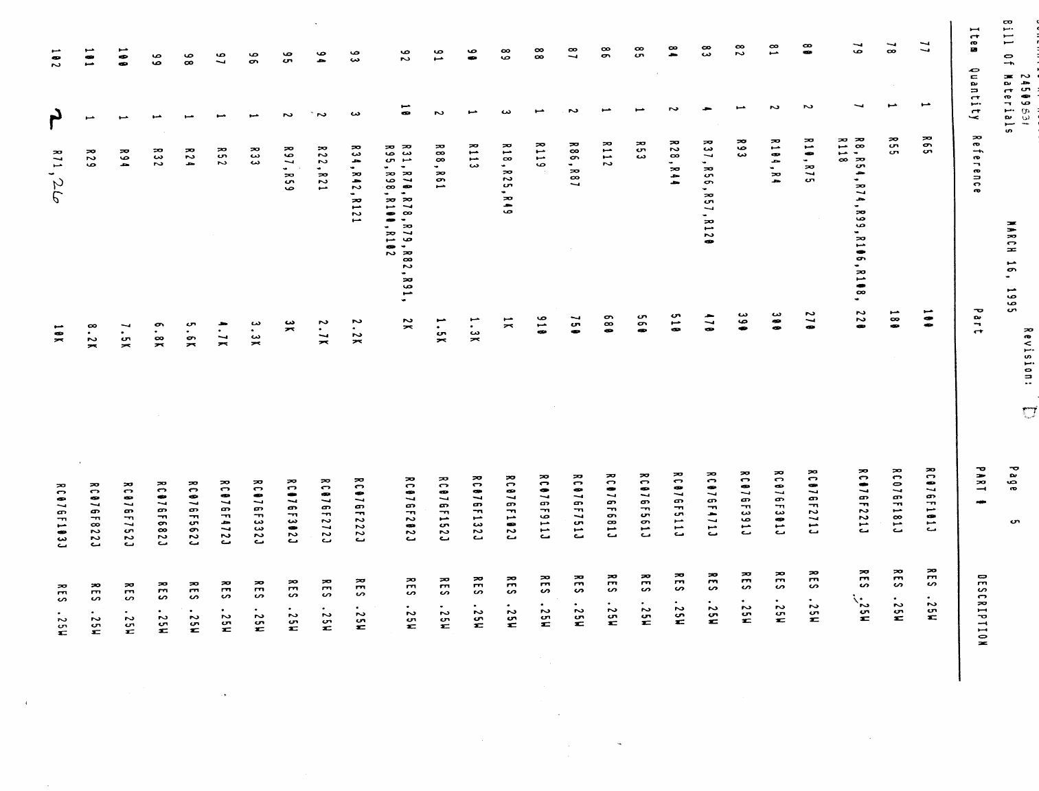
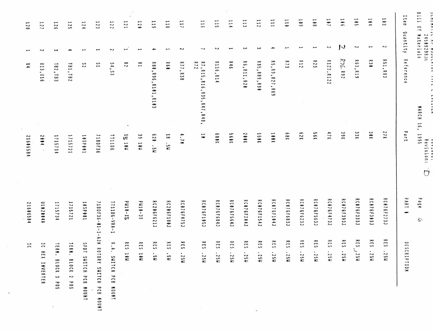
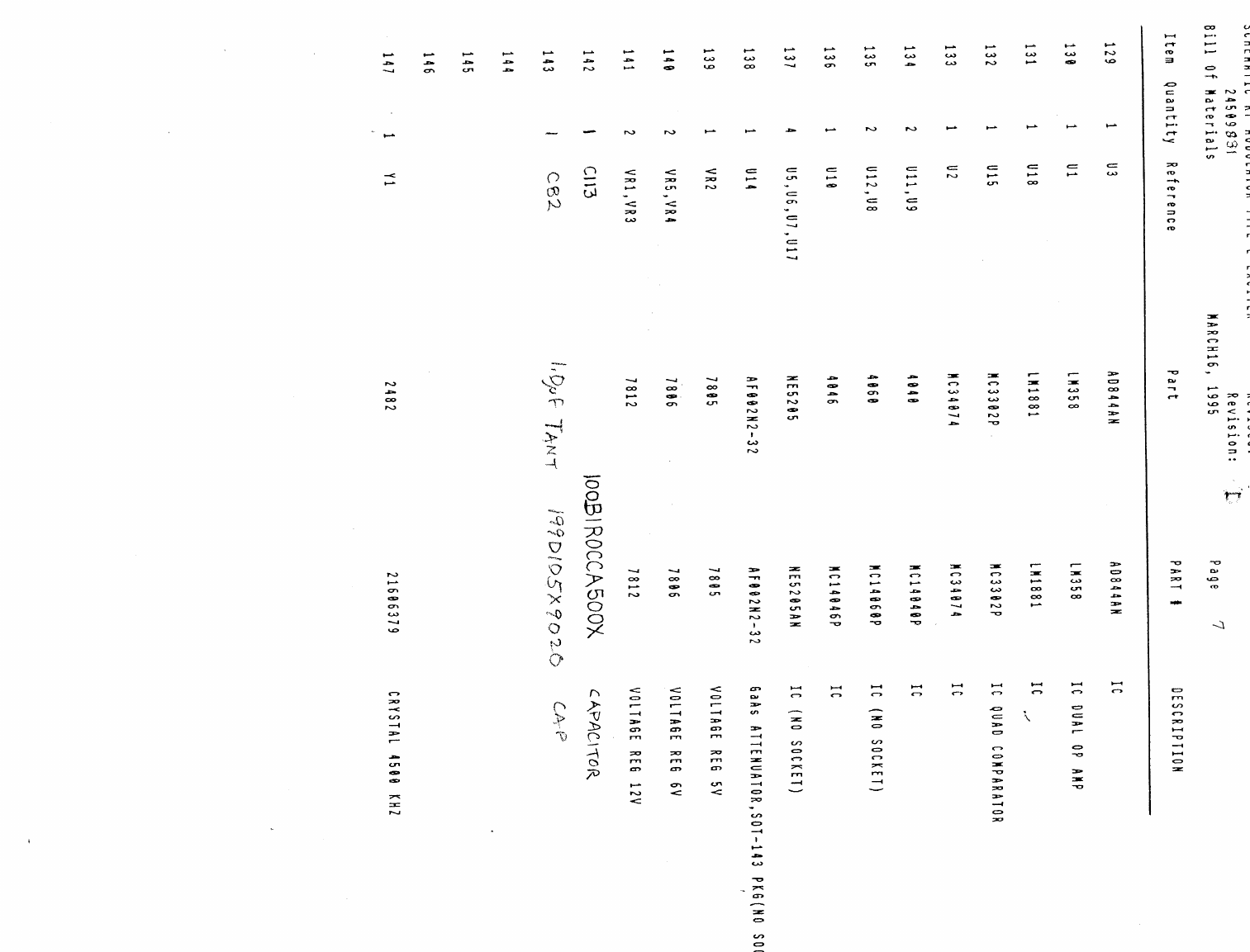
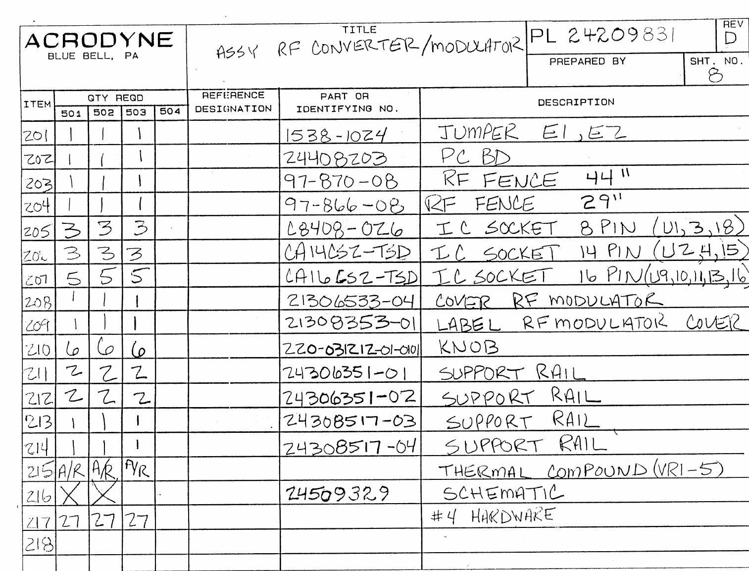
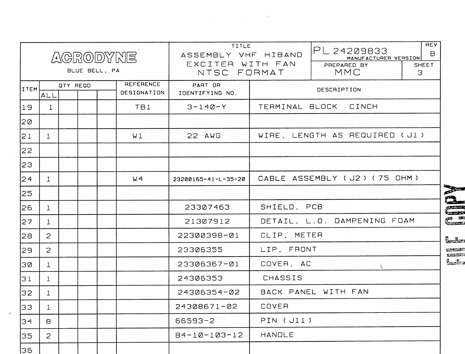
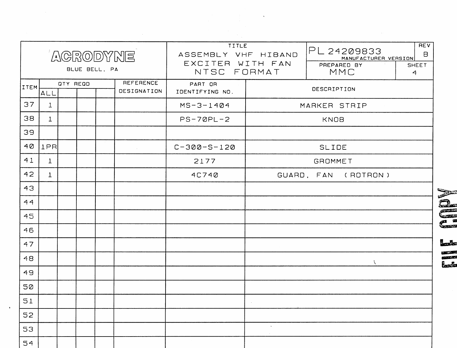
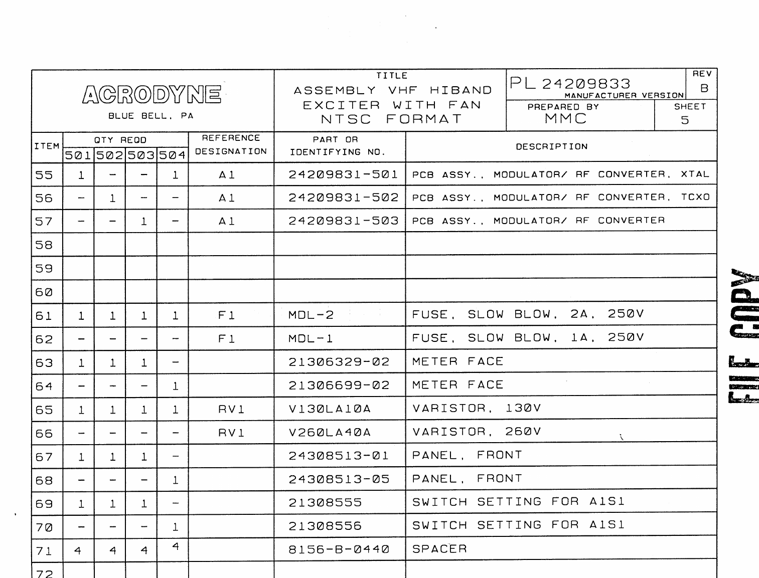
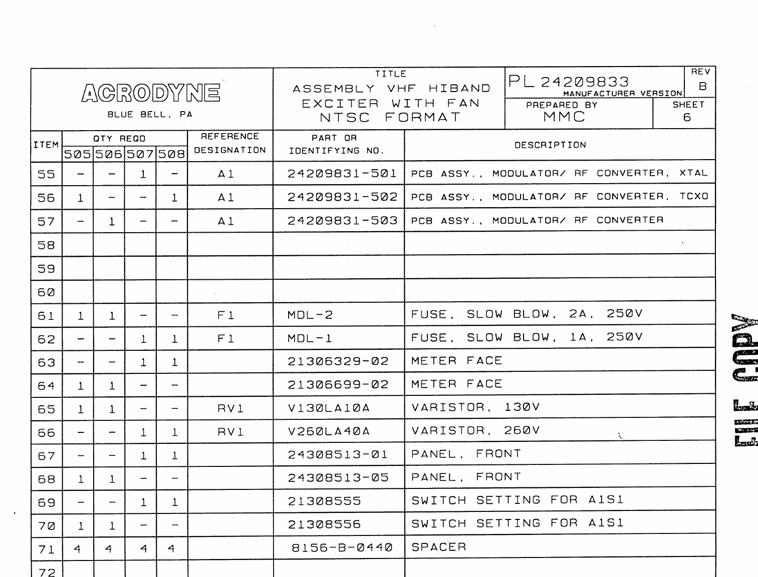
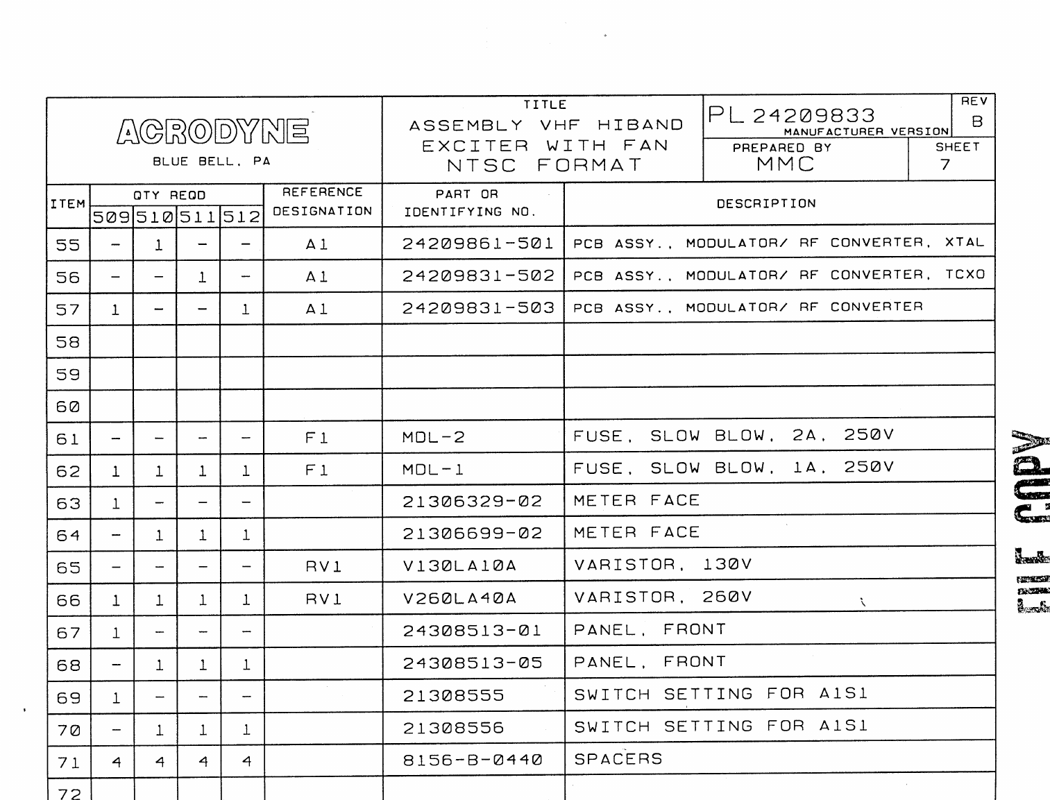
6.0 PARTS LISTS
The PARTS LISTS contained in this section are
placed in increasing numerical order. All lists are
identified by an eight digit number, beginning with
the number 2. Tabs are placed to divide the lists into
major subgroups defined by common numbers in the
second and third positions of the eight digit number.
Within each subgroup, the last four digits of the eight
digit list number determines its placement, again in
increasing numerical order.

TRH1KE_3.doc3.28-Jul-99 20
THIS PAGE LEFT BLANK

TRH1KE_3.doc3.28-Jul-99 21
7.0 TABLES AND REFERENCE DATA

TRH1KE_3.doc3.28-Jul-99 22
THIS PAGE LEFT BLANK

CCIR M/N CHANNEL ALLOCATIONS
23
Channel Frequency Visual Aural Local Osc. Channel Frequency Visual Aural Local Osc.
No. Band, MHz Carrier,
MHz Carrier,
MHz Frequency,
MHz No. Band, MHz Carrier
MHz Carrier
MHz Frequency
MHz
254-60 55.25 59.75 101 28 554-560 555.25 559.75 601
360-66 61.25 65.75 107 29 560-566 561.25 565.75 607
466-72 67.25 71.75 113 30 566-572 567.25 571.75 613
576-82 77.25 81.75 123 31 572-578 573.25 577.75 619
682-88 83.25 87.75 129 32 578-584 579.25 583.75 625
7174-180 175.25 179.75 221 33 584-590 585.25 589.75 631
8180-186 181.25 185.75 227 34 590-596 591.25 595.75 637
9186-192 187.25 191.75 233 35 596-602 597.25 601.75 643
10 192-198 193.25 197.75 239 36 602-608 603.25 607.75 649
11 198-204 199.25 203.75 245 37 608-614 609.25 613.75 655
12 204-210 205.25 209.75 251 38 614-620 615.25 619.75 661
13 210-216 211.25 215.75 257 39 620-626 621.25 625.75 667
14 470-476 471.25 475.75 517 40 626-632 627.25 631.75 673
15 476-482 477.25 481.75 523 41 632-638 633.25 637.75 679
16 482-488 483.25 487.75 529 42 638-644 639.25 643.75 685
17 488-494 489.25 493.75 535 43 644-650 645.25 649.75 691
18 494-500 495.25 499.75 541 44 650-656 651.25 655.75 697
19 500-506 501.25 505.75 547 45 656-662 657.25 661.75 703
20 506-512 507.25 511.75 553 46 662-668 663.25 667.75 709
21 512-518 513.25 517.75 559 47 668-674 669.25 673.75 715
22 518-524 519.25 523.75 565 48 674-680 675.25 679.75 721
23 524-530 525.25 529.75 571 49 680-686 681.25 685.75 727
24 530-536 531.25 535.75 577 50 686-692 687.25 691.75 733
25 536-542 537.25 541.75 583 51 692-698 693.25 697.75 739
26 542-548 543.25 547.75 589 52 698-704 699.25 703.75 745
27 548-554 549.25 553.75 595 53 704-710 705.25 709.75 751

CCIR M/N CHANNEL ALLOCATIONS
24
Channel Frequency Visual Aural Local Osc. Channel Frequency Visual Aural Local Osc.
No. Band, MHz Carrier,
MHz Carrier,
MHz Frequency,
MHz No. Band, MHz Carrier
MHz Carrier
MHz Frequency
MHz
54 710-716 711.25 715.75 757 62 758-764 759.25 763.75 805
55 716-722 717.25 721.75 763 63 764-770 765.25 769.75 811
56 722-728 723.25 727.75 769 64 770-776 771.25 775.75 817
57 728-734 729.25 733.75 775 65 776-782 777.25 781.75 823
58 734-740 735.25 739.75 781 66 782-788 783.25 787.75 829
59 740-746 741.25 745.75 787 67 788-794 789.25 793.75 835
60 746-752 747.25 751.75 793 68 794-800 795.25 799.75 841
61 752-758 753.25 757.75 799 69 800-806 801.25 805.75 847

CCIR B/G CHANNEL ALLOCATIONS
25
Channel Frequency Visual Aural Local Osc. Channel Frequency Visual Aural Local Osc.
No. Band, MHz Carrier,
MHz Carrier,
MHz Frequency,
MHz No. Band, MHz Carrier
MHz Carrier
MHz Frequency
MHz
E2 47-54 48.25 53.75 87.15 E36 590-598 591.25 596.75 630.15
E3 54-61 55.25 60.75 94.15 E37 598-606 599.25 604.75 638.15
E4 61-68 62.25 67.75 101.15 E38 606-614 607.25 612.75 646.15
E5 174-181 175.25 180.75 214.15 E39 614-622 615.25 620.75 654.15
E6 181-188 182.25 187.75 221.15 E40 622-630 623.25 628.75 662.15
E7 188-195 189.25 194.75 228.15 E41 630-638 631.25 636.75 670.15
E8 195-202 196.25 201.75 235.15 E42 638-646 639.25 644.75 678.15
E9 202-209 203.25 208.75 242.15 E43 646-654 647.25 652.75 686.15
E10 209-216 210.25 215.75 249.15 E44 654-662 655.25 660.75 694.15
E11 216-223 217.25 222.75 256.15 E45 662-670 663.25 668.75 702.15
E12 223-230 224.25 229.75 263.15 E46 670-678 671.25 676.75 710.15
E21 470-478 471.25 476.75 510.15 E47 678-686 679.25 684.75 718.15
E22 478-486 479..25 484.75 518.25 E48 686-694 687.25 692.75 726.15
E23 486-494 487.25 492.75 526.15 E49 694-702 695.25 700.75 734.15
E24 494-502 495.25 500.75 534.15 E50 702-710 703.25 708.75 742.15
E25 502-510 503.25 508.75 542.15 E51 710-718 711.25 716.75 750.15
E26 510-518 511.25 516.75 550.15 E52 718-726 719.25 724.75 758.15
E27 518-526 529.25 524.75 558.15 E53 726-734 727.25 732.75 766.15
E28 526-534 527.25 532.75 566.15 E54 734-742 735.25 740.75 774.15
E29 534-542 535.25 540.75 574.15 E55 742-750 743.25 748.75 782.15
E30 542-550 543.25 548.75 582.15 E56 750-758 751.25 756.75 790.15
E31 550-558 551.25 556.75 590.15 E57 758-766 759.25 764.75 798.15
E32 558-566 559.25 564.75 598.15 E58 766-774 767.25 772.75 806.15
E33 566-574 567.25 572.75 606.15 E59 774-782 775.25 780.75 814.15
E34 574-582 575.25 580.75 614.15 E60 782-790 783.25 788.75 822.15
E35 582-590 583.25 588.75 622.15 E61 790-798 791.25 796.75 830.15

CCIR B/G CHANNEL ALLOCATIONS
26
Channel Frequency Visual Aural Local Osc. Channel Frequency Visual Aural Local Osc.
No. Band, MHz Carrier,
MHz Carrier,
MHz Frequency,
MHz No. Band, MHz Carrier
MHz Carrier
MHz Frequency
MHz
E62 798-806 799.25 804.75 838.15 E66 830-838 831.25 836.75 870.15
E63 806-814 807.25 812.75 846.15 E67 838-846 839.25 844.75 878.15
E64 814-822 815.25 820.75 854.15 E68 846-854 847.25 852.75 886.15
E65 822-830 823.25 828.75 862.15
27
dBm to Microvolt Conversion Table
dBm Microvolts/50 ohms Microvolts/75 ohms
0223,607 273,861
-5 125,743 154,004
-10 70,711 86,603
-15 39,764 48,700
-20 22,361 27,386
-25 12,574 15,400
-30 7,071 8,660
-35 3,976 4,870
-40 2,236 2,739
-45 1,257 1,540
-50 707 866
-55 398 487
-60 224 274
-65 126 154
-70 71 87
-75 40 49
Cable loss table. Loss figures listed in dB per 100 foot.
CABLE TYPE CHANNEL
2-4 CHANNEL
5-6 CHANNEL
7-13 CHANNEL 14-41 CHANNEL 42-69
RG58/U (50 ohm) 3.5 4.0 7.0 15 18
RG59/U (75 ohm) 2.6 3.0 4.9 8.6 10
RG8/U (50 ohm) 1.6 1.8 3.2 6.1 7.2
RG11/U (75 ohm) 1.7 1.8 3.2 6.1 7.2
3/8” Foam 0.9 1.0 1.5 2.9 3.2
½” Foam 0.66 0.75 1.2 2.2 2.7
7/8” Foam 0.4 0.45 0.7 1.5 1.8
3/8” Air 0.96 1.1 1.7 3.0 3.6
½” Air 0.64 0.71 1.1 1.9 2.2
International Morse Code
A• _ M_ _ Y_ • _ _
B_ • • •N_ •Z_ _ • •
C_ • _ •O_ _ _ 0_ _ _ _ _
D_ • •P• _ _ •1• _ _ _ _
E•Q_ _ • _ 2• • _ _ _
F• • _ •R• _ •3• • • _ _
G_ _ •S• • •4• • • • _
H• • • •T_ 5 • • • • •
I• •U• • _ 6_ • • • •
J• _ _ _ V• • • _ 7_ _ • • •
K_ • _ W• _ _ 8_ _ _ • •
L• _ • •X_ • • _ 9_ _ _ _ •
TLH/1KE#2.28-Jul-99 i

TLH/1KE#2.28-Jul-99 i
TABLE OF CONTENTS
TRH/1KE TELEVISION TRANSMITTER
INSTALLATION AND OPERATORS MANUAL
1.0 GENERAL INFORMATION..............................................................................................................................1
1.1 INTRODUCTION ............................................................................................................................................1
1.2 DESCRIPTION.................................................................................................................................................1
1.3 SPECIFICATIONS...........................................................................................................................................3
1.4 ILLUSTRATION LIST ....................................................................................................................................6
2.0 INSTALLATION..................................................................................................................................................7
2.1 INTRODUCTION ............................................................................................................................................7
2.2 UNPACKING AND INSPECTION .................................................................................................................7
2.3 SITE CONSIDERATIONS...............................................................................................................................7
2.4 CABINET INSTALLATION ...........................................................................................................................8
2.5 EXTERNAL CONNECTIONS.........................................................................................................................8
2.5.1 AC MAINS...............................................................................................................................................8
2.5.2 OUTPUT TRANSMISSION LINE AND ANTENNA............................................................................9
2.5.3 AUDIO/VIDEO INPUTS.......................................................................................................................10
3.0 OPERATION......................................................................................................................................................11
3.1 INTRODUCTION ..........................................................................................................................................11
3.2 OPERATING PROCEDURES .......................................................................................................................11
3.2.1 MANUAL TURN ON.............................................................................................................................11
3.2.2 AUTOMATIC AND REMOTE TURN ON...........................................................................................11
3.2.3 EQUIPMENT TURN OFF.....................................................................................................................12
5.0 MAINTENANCE................................................................................................................................................13
5.1 INTRODUCTION ..........................................................................................................................................13
5.2 RF POWER METER CALIBRATION AND AGC SET POINT ADJUST...................................................13
5.3 VIDEO AND IF PROCESSOR ADJUSTMENTS .........................................................................................14
5.4 AMPLIFIER BYPASS OPERATION............................................................................................................16
5.5 RF TRANSISTOR REPLACEMENT ............................................................................................................17
5.6 CLEANING AND MAINTENANCE SCHEDULE.......................................................................................17
6.0 PARTS LISTS.....................................................................................................................................................19
7.0 TABLES AND REFERENCE DATA ...............................................................................................................21
JOB NO.
NEXT ASSY.
USED ON
REF. DES.
ASSY
DESCRIPTION
-501
STANDARD
-502
FOR USE IN ‘E’ TYPE EXITER
-503
STANDARD WITH STRAIGHT POT
ECN LTR DESCRIPTION REVISED BY APPROVED BY
AADDED -502 CMI - 2/25/97 MB - 3/97
2824 BJ1 REMOVED FROM -502 hcc - 4/97 MB - 4/97
3100 CW1 MOVED FROM UPPER ASSEMBLY 22211152 TO HERE, UPGRADE TO WORD/ACAD hcc - 5/98 MB - 05/97
DADDED -503 ASSEMBLY VERSION. MTS - 06/98
3294 EPART NUMBER 5 WAS 100B102KC5OX, #30 WAS PFK-632-40 JJC 12/21/98 DM 12/21/98
3321
3342 FITEMS 11 & 12 WERE RFB-1113 JJC 3/19/99
ACRODYNE INDUSTRIES
516 TOWNSHIP LINE ROAD
BLUE BELL, PA. 19422
TITLE
VISUAL/AURAL IF COMBINER
CODE IDENT
51336 DOCUMENT NUMBER
PL21209419
REVISION
F
PREPARED BY
C. MOORE
CHECKED BY
J. BROOKES
DATE
5/15/95
DATE
APPROVED BY
M. BRICKER DATE
8/95
ACRODYNE
SHEET 1 OF 3
QUANTITY REQUIRED REFERENCE PART OR
ITEM -501 -502 -503 -504 DES. IDENTIFYING NUMBER DESCRIPTION VENDER
PL 21209419 rev F
ACRODYNE
BLUE BELL, PA
Title
VISUAL/AURAL
IF COMBINER PREPARED BY
hcc SHEET NO.
2
2
1X X X X 22509478 SCHEMATIC
2
3
4 2 2 2 C1,2 21CC647 CAPACITOR CHIP, 470pf
5 1 1 1 C3 100B102MP50X CAPACITOR CHIP, 1000pf
6 1 1 1 C4 RPE121Z5U104M50 CAPACITOR CHIP, 0.1uf
7 4 4 4 C5,6,8,9 199D105X0035AA1 CAPACITOR CHIP, 1uf, 35V, TANT
8 1 1 1 C7 199D226X0035 CAPACITOR CHIP, 22uf, 35V, TANT
9 1 1 1 CR1 1N4002 DIODE
10 1 1 1 F1 2664000101 FERRITE BEAD
11 2 -2J1,2 RFB-1111 BNC CONNECTOR
12 -1-J2 RFB-1111 BNC CONNECTOR
13 2 2 2 L1,2 TKS2518CT COIL
14 -1 1 R1 3339P-1-500 POTENTIOMETER, 50 ohm
15 1 - - R1 3339W-1-500 POTENTIOMETER, 50 ohm, RIGHT ANGLE
16 4 4 4 R2,4,8,
15 RC07GF101J RESISTOR, 100 ohm, ¼ WATT
17 3 3 3 R3,11,13 RC07GF510J RESISTOR, 51 ohm, ¼ WATT
18 4 4 4 R5,7,10,
14 RC07GF241J RESISTOR, 240 ohm, ¼ WATT
19 1 1 1 R6 3339P-1-500 POTENTIOMETER, 50 ohm
20 1 1 1 R9 RC07GF620J RESISTOR, 62 ohm, ¼ WATT
21 1 1 1 R12 RC07GF301J RESISTOR, 300 ohm, ¼ WATT
22 1 1 1 R16 RC07GF100J RESISTOR, 10 ohm, ¼ WATT
23 1 1 1 TB1 1715721 TERMINAL BLOCK, 2 POSITION
24 1 1 1 U1 NE5205AN I.C. (NO SOCKET)
25 1 1 1 VR1 7806 VOLTAGE REGULATOR
26 1 1 1 W1 23200165-41-L-5-12 ASSEMBLY, CABLE, A3/AURAL OUT to A2E2
27
28
29 1 1 1 21409418 P.C. BOARD

QUANTITY REQUIRED REFERENCE PART OR
ITEM -501 -502 -503 -504 DES. IDENTIFYING NUMBER DESCRIPTION VENDER
PL 21209419 rev F
ACRODYNE
BLUE BELL, PA
Title
VISUAL/AURAL
IF COMBINER PREPARED BY
hcc SHEET NO.
3
3
30 2 2 2 PFC2-632-40 CAPTIVE SCREW
31 A/R A/R A/R #18 AWG BUSS WIRE
JOB NO.
NEXT ASSY.
USED ON
REF. DES.
ASSY
DESCRIPTION
-501 240/120 VAC
-502 240/120 VAC, FUSE BD ,22212251, DUAL POWER
SUPPLIES. WIRING DIAGRAM 22513177 REV -
-503 230 VAC SINGLE PHASE, SINGLE POWER
SUPPLY,WIRING DIAGRAM 22513177 REV A.
ECN LTR DESCRIPTION REVISED BY APPROVED BY
A CREATED -502 VERSION SMJ MB - 5/99
BCREATED -503 VERSION KPOOLE
ACRODYNE INDUSTRIES
516 TOWNSHIP LINE ROAD
BLUE BELL, PA. 19422
TITLE
ASSEMBLY, TRH/1KE CABINET
CODE IDENT
51336 DOCUMENT NUMBER
PL22111237-502 REVISION
B
PREPARED BY
KPOOLE
CHECKED BY
DATE
7/97
DATE
APPROVED BY
BRICKER DATE
8/97
ACRODYNE
SHEET 1 OF 3

QUAN. REFERENCE PART OR
ITEM REQD. DESIGNATION IDENTIFYING NUMBER DESCRIPTION VENDER
502
REV. B
Title
ASSEMBLY,
TRH/1KE CABINET
PL22111237-502
ACRODYNE
BLUE BELL, PA SHEET NO.
2
PREPARED BY
KPOOLE
1REF 22513177 CABINET WIRING HARNESS DIAGRAM
2REF 22513365 CABINET BLOCK AND CABLING DIAGRAM
3
4
5 1 A1 22211753-501 ASSEMBLY, VIDEO PROCESSOR CHASSIS
6 1 A2 24209833-506 ASSEMBLY, EXCITER CHASSIS
7 1 A3 22211856-501 ASSEMBLY, IF PROCESSOR CHASSIS
8 1 A4 22209840-501 ASSEMBLY, 1 WATT AMP. CHASSIS
9 1 A5 23209084-502 ASSEMBLY, 30 WATT IPA CHASSIS
10 2 A6, A7 24209082-501 ASSEMBLY, 600 WATT PA CHASSIS
11 3 A8, A9, A10 22207801-501 ASSEMBLY, HYBRID COMBINER
12 1 A11 22212251-502 ASSEMBLY, POWER SUPPLY FUSE BOARD
13 1 A12 23208793-507 ASSEMBLY, LOAD/HEATSINK
14 1 A13 21611236 COUPLER, 2 FORWARD PORTS, 1-5/8”
15 1 A14 21609485-05 BANDPASS FILTER
16 1 A15 23206588-504 ASSEMBLY, CONTROL LOGIC CHASSIS
17 1 A16 21611227 COUPLER, 1 FORWARD/1 REVERSE, N TYPE CONNECTOR
18 1 A17 22213117-501 ASSEMBLY, 24 V POWER SUPPLY
19 1 A18 21607059-502 ASSEMBLY, CIRCULATOR
20 1 A19 22212570-502 ASSEMBLY, POWER SUPPLY CONTROL CABLE
21 1 A20 22213359-01 ASSEMBLY, SIDE PANEL RIGHT
22 1 A21 22213359-02 ASSEMBLY, SIDE PANEL LEFT
23 1 A22 22113371-02 ASSEMBLY, CABINET WIRE HARNESS
24 1 A23 CL13365 CABINET CABLE LIST
25 1 AT1 8141 LOAD, 50 OHM, 250 WATT
26 1 AT2 8201 LOAD, 50 OHM, 500 WATT
27 2 CB1, 2 S272-K20 CIRCUIT BREAKER, 2 POLE, 20 AMP
28 1 CB3 374-210-101 CIRCUIT BREAKER, 1 POLE, 10 AMP
29
30 2 CR1, 2 CD50 DETECTOR DIODE
31 2 PS1, 2 HC20-C1164 POWER SUPPLY, 28 VDC, 72 AMP
32 1 S1 OETL-NF60S SWITCH, AC MAINS
33 1 22310957-011 AC BOX MOUNTING ANGLE
34

QUAN. REFERENCE PART OR
ITEM REQD. DESIGNATION IDENTIFYING NUMBER DESCRIPTION VENDER
502
REV. B
Title
ASSEMBLY,
TRH/1KE CABINET
PL22111237-502
ACRODYNE
BLUE BELL, PA SHEET NO.
3
PREPARED BY
KPOOLE
35
36
37 1 AC BOX, 4X4X2,WITH COVER, UNPAINTED
38 1 AC BOX, 4X4X2,WITH COVER, PAINTED GREY
39 1 22300881 BEZEL
40 1 22300882 BEZEL
41 2 22301034-1 BLANK PANEL, 1.75”
42 1 21308876 PANEL BRACKET
43 1 22208884 CABINET SKELETON
44
45 1 24308379-515 CIRCUIT BREAKER PANEL, 208Y/120 VAC
46 1 22311302 DETAIL, CIRCULATOR PLATE
47 1 21308853 VERTICAL BLANK PANEL
48 1 22311297 DETAIL, COMBINER MOUNTING PANEL
49
50 1 22307714 SAFETY SCREEN
51 1 22307715 SAFETY SCREEN
52 1 22307583-02 ANGLE SUPPORT
53 2 22308381 POWER SUPPLY MOUNTING PLATE
54
55
56
57
58
59
60
61
62
63
64
65
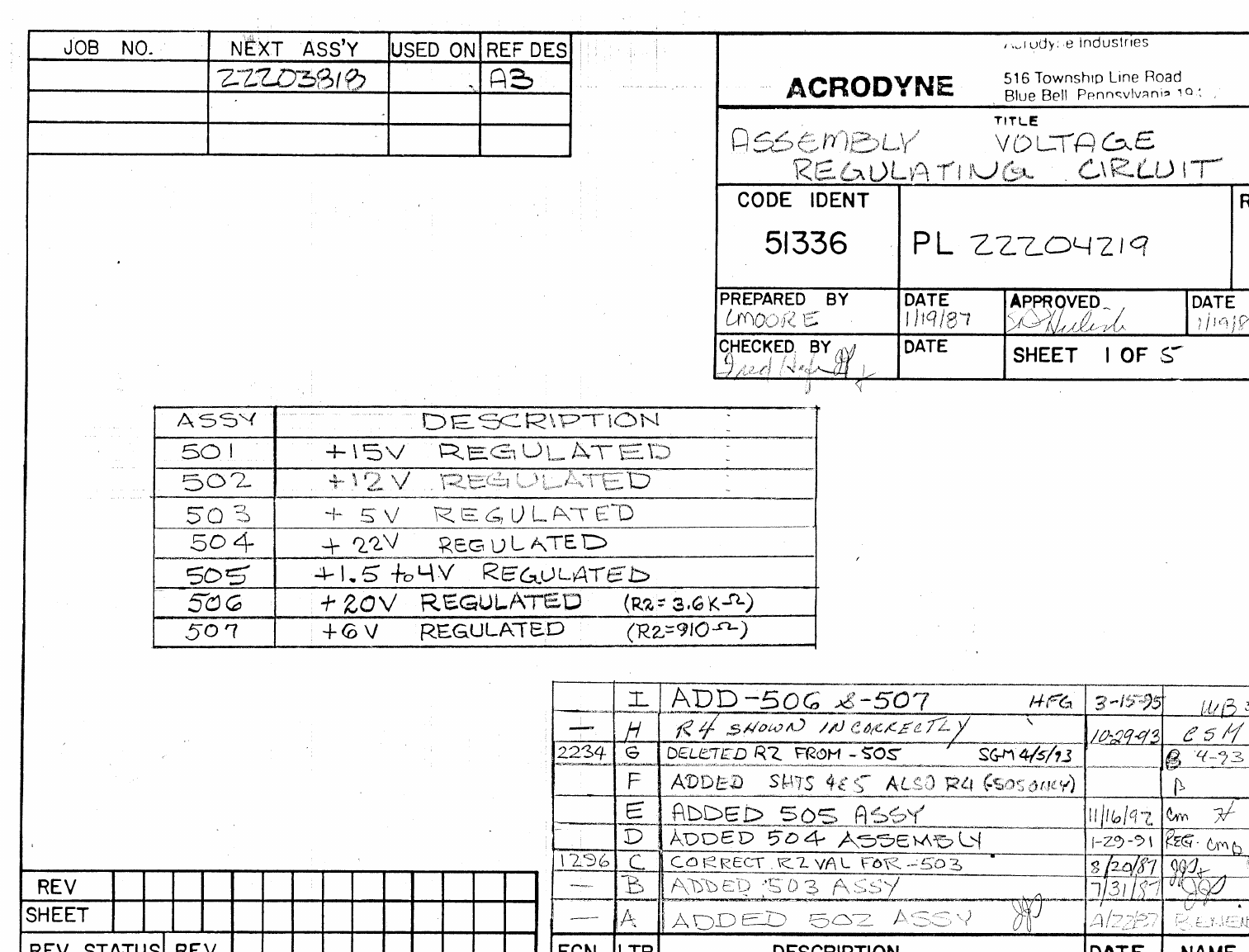
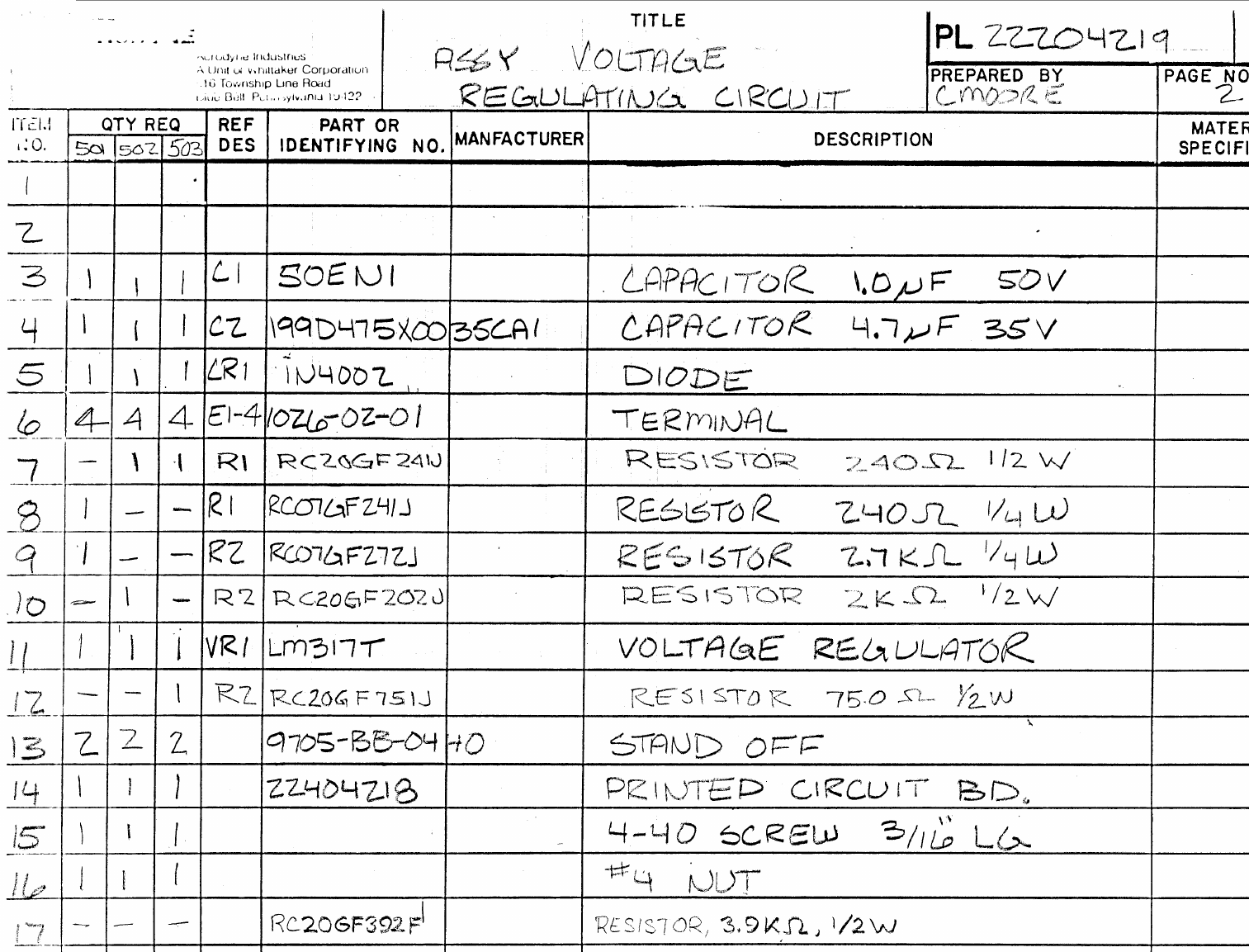
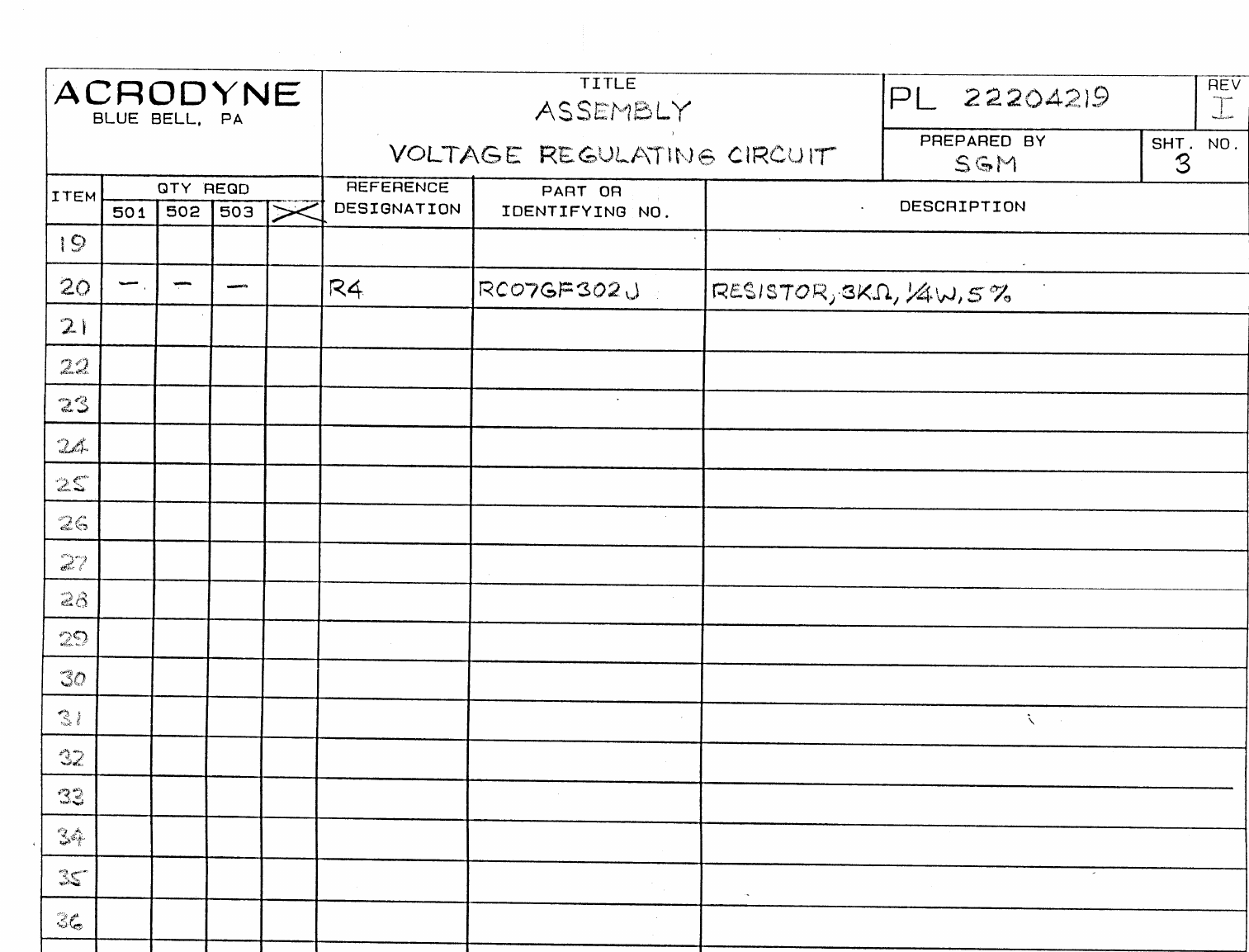
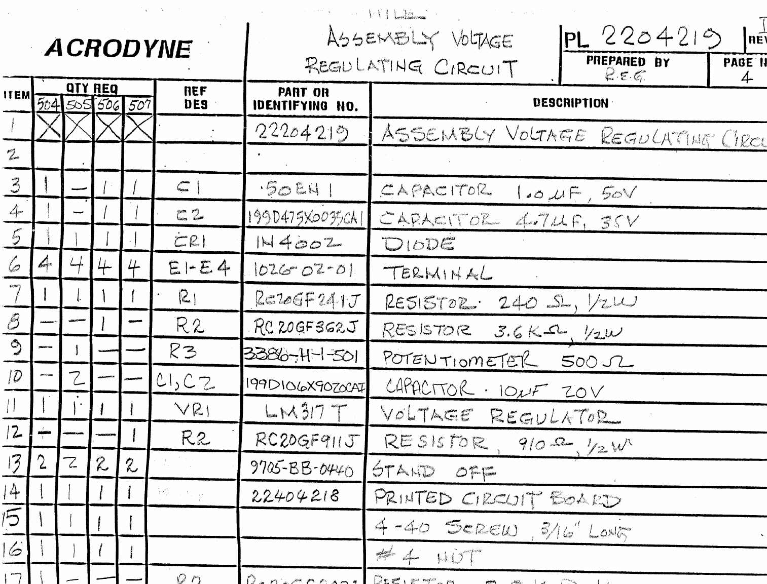
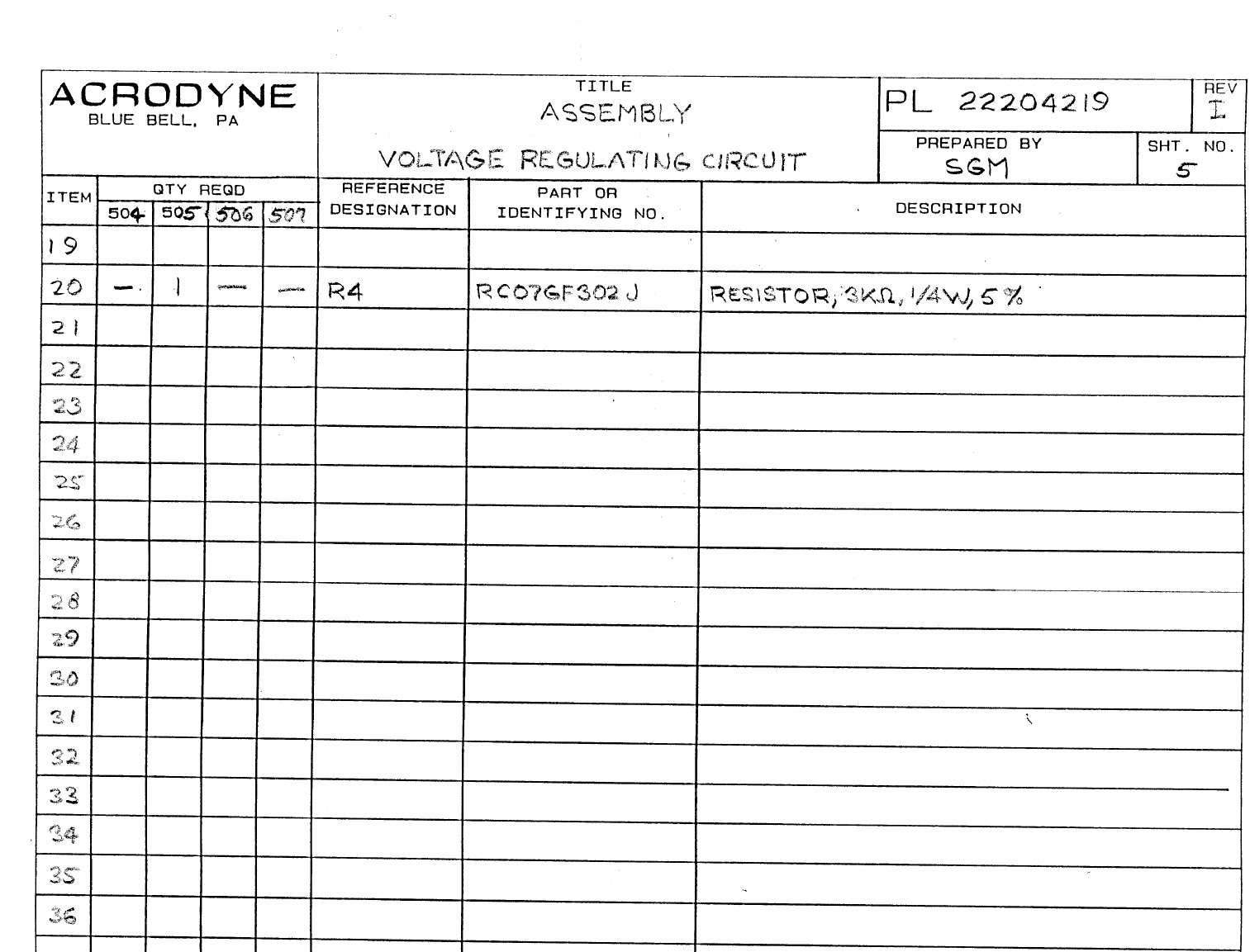
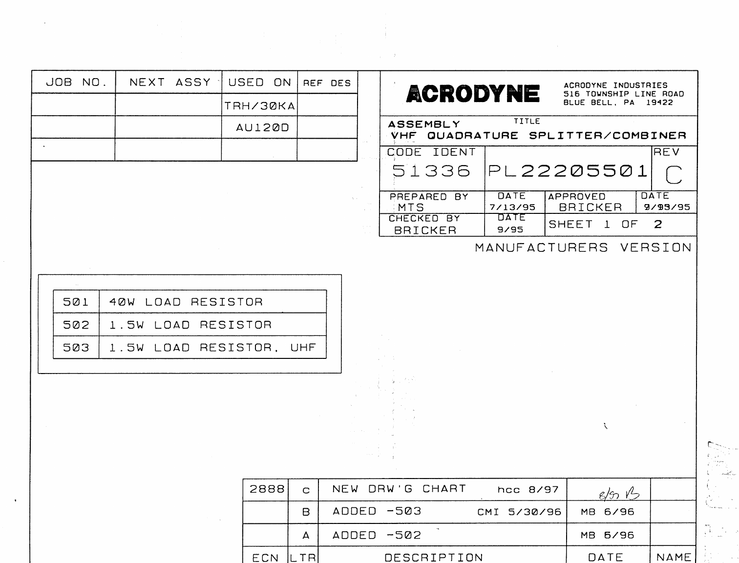
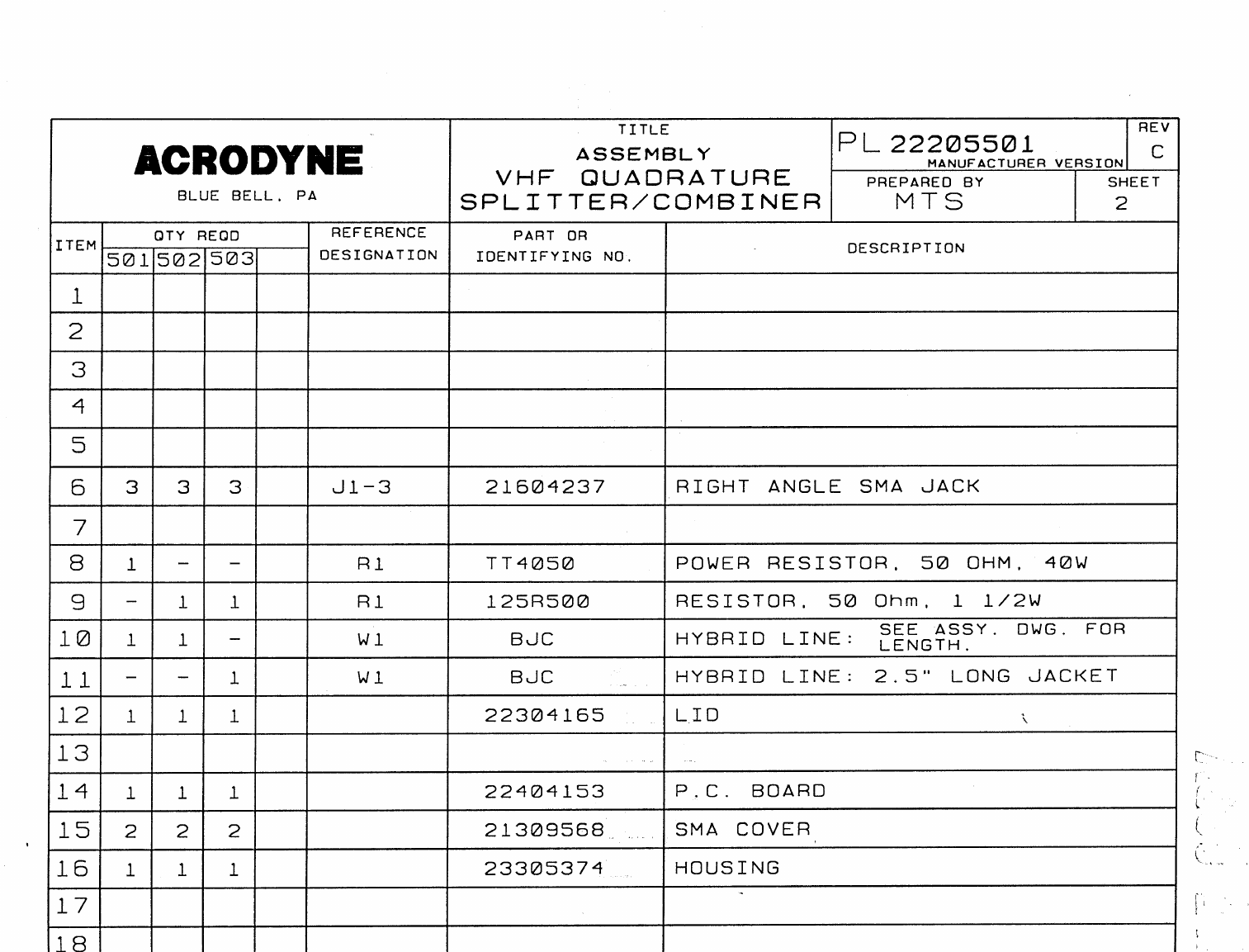
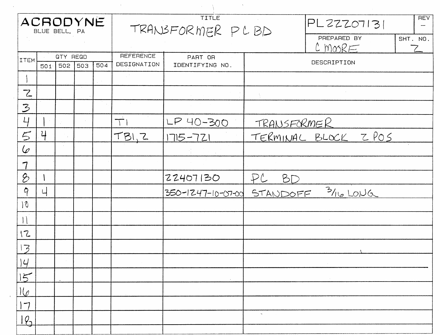
JOB NO.
NEXT ASSY.
USED ON
REF. DES.
ASSY
DESCRIPTION
-501
DIGITAL METER/15-24 VDC IN/4.5 MHZ AURAL
-502
ANALOG METER/15-24 VDC IN/4.5 MHZ AURAL
-503
DIGITAL METER/12 VDC IN/4.5 MHZ AURAL
-504
ANALOG METER/12 VDC IN/4.5 MHZ AURAL
-505
DIGITAL METER/15-24 VDC IN/ 5.5 or 6.5 MHZ AURAL
-506
ANALOG METER/15-24 VDC IN/5.5 or 6.5 MHZ AURAL
-507
DIGITAL METER/12 VDC IN/5.5 or 6.5 MHZ AURAL
-508
ANALOG METER/12 VDC IN/5.5 or6.5 MHZ AURAL
ECN LTR DESCRIPTION REVISED BY APPROVED BY
AADDED ¾” STANDOFFS 3/26/93 JKC
2226 BDELETED C12 5/93 JKC
2321 CNEW PCB LAYOUT 3/94 CM
2374 DADDED C40 & CR12 5/94 CM
ECHANGED DRAWING TO REFLECT ECN 2374 5/27/94 SGM MB 6/3/94
2445 FCHANGED J1 & J2 PART # MTS 5/15/95
GUPDATED ITEMS 98,99 & 100 MTS 9/29/95
2909 HADDED R78 HFG 9/97 MB 9/97
2983 IITEMS 11 & 12 WERE CK06BX104K HFG 12/97 MB 1/98
3026 JECN CHANGED & UPGRADED EVERYTHING TO WORD/ACAD hcc 3/98
3124 KCHANGED QUANTITY OF #98, FIXED PART #’S ON #197, 108 JJC 6/98 MV 6/98
LNEW ARTWORK, CHIP CAPS FOR 0.1 UF’S, CORRECTED LINE 17. MMC 7/98
3307 MCHANGED P/N ITEMS 37, 38 ,39 AJG 12/98
ACRODYNE INDUSTRIES
516 TOWNSHIP LINE ROAD
BLUE BELL, PA. 19422
TITLE
Assembly, RF Power Monitor
CODE IDENT
51336 DOCUMENT NUMBER
PL22207217
REVISION
M
PREPARED BY
C. MOORE
CHECKED BY
M. BRICKER
DATE
1/6/94
DATE
5/23/94
APPROVED BY
M. BRICKER DATE
5/23/94
ACRODYNE
SHEET 1 OF 5

QUANTITY REQUIRED REFERENCE PART OR
ITEM -501 -502 -503 -504 -505 -506 -507 -508 DES. IDENTIFYING NUMBER DESCRIPTION
PL 22207217 rev M
ACRODYNE
BLUE BELL, PA
Title
Assembly, RF Power
Monitor PREPARED BY
C. MOORE SHEET NO.
2
2
1X X X 23507062 SCHEMATIC
2X X X 23508231 SCHEMATIC
3X X X 23508230 SCHEMATIC
4X X X 23508232 SCHEMATIC
5 2 2 2 2 C2,4 DM15-561J CAPACITOR, 560 pf
6 2 2 2 2 C3,5 DM15-471J CAPACITOR, 470 pf
7 2 2 2 2 C2,4 DM15-471J CAPACITOR, 470 pf
8 2 2 2 2 C3,5 DM15-431J CAPACITOR, 430 pf
9 1 1 1 1 1 1 1 1 C16 CK05BX103K CAPACITOR, 0.01uf
10 1 -1-1-1-C39 CK05BX103K CAPACITOR, 0.01uf
11 12 12 12 12 12 12 12 12 C12,18,
20,22-29,38 GRM42-6X7R104K050BL CAPACITOR, 0.1uf
12 1 -1-1-1-C30 GRM42-6X7R104K050BL CAPACITOR, 0.1uf
13 1 1 1 1 1 1 1 1 C1 DM10-161J CAPACITOR, 160pf
14 4 4 4 4 4 4 4 4 C13,17,34,35 199D106X9020CAI CAPACITOR, 10uf, 20V, TANT
15 2 2 2 2 2 2 2 2 C19,21 199D225X0035BAI CAPACITOR, 2.2uf, 35V, TANT
16 4 4 4 4 4 4 4 4 C7,8,
36,37 199D476X96R3D CAPACITOR, 47uf, 63V, TANT
17 2 2 - - 2 2 - - C31,32 199D106X9020CAI CAPACITOR, 10uf, 20V TANT
18 2 2 2 2 2 2 2 2 C6,C40 10ENIT CAPACITOR, 1000uf, 10V
19 1 1 1 1 1 1 1 1 C33 TLB1H102M CAPACITOR, 1000uf, 50V
20 9 9 9 9 9 9 9 9 F1-9 DST310-SSY55-223M FILTER ELEMENT
21 3 3 3 3 3 3 3 3 E1-6 65507-436 TWO PIN HEADER
22 4 -4-4-4-C10,11,14,15 199D105X0035CA CAPACITOR, 1uf, 35V, TANT
23 1 1 1 1 1 1 1 1 C9 199D475X0035CA CAPACITOR, 4.7uf, 35V, TANT
24
25 3 3 3 3 3 3 3 3 J1-3 RFB-1111 BNC JACK
26
27 2 2 2 2 - - - - L1,3 1025-36 INDUCTOR, 4.7uH
28 1 1 1 1 - - - - L2 1025-20 INDUCTOR, 1.0uH
29
30 1 1 1 1 1 1 1 1 CR12 1N914 DIODE
31 3 3 3 3 3 3 3 3 CR6,10,11 1N4007 DIODE

QUANTITY REQUIRED REFERENCE PART OR
ITEM -501 -502 -503 -504 -505 -506 -507 -508 DES. IDENTIFYING NUMBER DESCRIPTION
PL 22207217 rev M
ACRODYNE
BLUE BELL, PA
Title
Assembly, RF Power
Monitor PREPARED BY
C. MOORE SHEET NO.
3
3
32 1 1 - - 1 1 - - CR9 1N4007 DIODE
33 2 2 2 2 2 2 2 2 CR4,8 1N4148A DIODE
34 3 3 3 3 3 3 3 3 CR1,3,7 1N5711 DIODE
35 2 2 2 2 2 2 2 2 CR2,5 35BL504 LED, RED
36 1 1 1 1 1 1 1 1 Q1 2N3904 TRANSISTOR
37 3 3 3 3 3 3 3 3 R6,24,65 3339P-1-102 POTENTIOMETER, 1.0K OHM
38 1 1 1 1 1 1 1 1 R46 3339P-1-103 POTENTIOMETER, 10K OHM
39 1 1 1 1 1 1 1 1 R22 3339P-1-104 POTENTIOMETER, 100K OHM
40 1 1 1 1 1 1 1 1 R3 RN55C49R9F RESISTOR, 49.9 OHM, 1/8W, 1%
41 2 2 2 2 2 2 2 2 R8,30 RN55C2000F RESISTOR, 200 OHM, 1/8W, 1%
42 2 2 2 2 2 2 2 2 R4,7 RN55C374OF RESISTOR, 374 OHM, 1/8W, 1%
43 5 5 5 5 5 5 5 5 R26,27,
63,68,71 RN55C1001F RESISTOR, 1.00K OHM, 1/8W, 1%
44 2 2 2 2 2 2 2 2 R15,50 RN55C1821F RESISTOR, 1.82K OHM, 1/8W, 1%
45 1 1 1 1 1 1 1 1 R31 RN55C2211F RESISTOR, 2.21K OHM, 1/8W, 1%
46 -1-1-1-1R33 RN55C619IF RESISTOR, 6.19K OHM, 1/8W, 1%
47 -1-1-1-1R13 RN55C7501F RESISTOR, 7.50K OHM, 1/8W, 1%
48 2 2 2 2 2 2 2 2 R14,49 RN55C8251F RESISTOR, 8.25K OHM, 1/8W, 1%
49 1 1 1 1 1 1 1 1 R11 RN55C1002F RESISTOR, 10.0K OHM, 1/8W, 1%
50 1 1 1 1 1 1 1 1 R59 RN55C5622F RESISTOR, 56.2K OHM, 1/8W, 1%
51 1 1 1 1 1 1 1 1 R56 RN55C2742F RESISTOR, 27.4K OHM, 1/8W, 1%
52 1 1 1 1 1 1 1 1 R45 RN55C3322F RESISTOR, 33.2K OHM, 1/8W, 1%
53 1 1 1 1 1 1 1 1 R12 RN55C1003F RESISTOR, 100K OHM, 1/8W, 1%
54 2 2 2 2 2 2 2 2 R1,2 RC07FG4R7J RESISTOR, 4.7 OHM, 1/4W
55 4 4 4 4 4 4 4 4 R9,10,
25,64 RC07GF100J RESISTOR, 10 OHM, 1/4W
56 5 5 5 5 5 5 5 5 R17,40,
48,51,58 RC07GF101J RESISTOR, 100 OHM, 1/4W
57 2 2 2 2 2 2 2 2 R66,67 RC07GF201J RESISTOR, 200 OHM, 1/4W
58 1 1 1 1 1 1 1 1 R5 RC07GF301J RESISTOR, 300 OHM, 1/4W
59 1 1 1 1 1 1 1 1 R52 RC07GF511J RESISTOR, 510 OHM, 1/4W
60 10 10 10 10 10 10 10 10 R16,29,
54,61,62,69,70,
73,75,77
RC07GF102J RESISTOR, 1K OHM, 1/4W
61 2 2 2 2 2 2 2 2 R43,44 RC07GF512J RESISTOR, 5.1K OHM, 1/4W

QUANTITY REQUIRED REFERENCE PART OR
ITEM -501 -502 -503 -504 -505 -506 -507 -508 DES. IDENTIFYING NUMBER DESCRIPTION
PL 22207217 rev M
ACRODYNE
BLUE BELL, PA
Title
Assembly, RF Power
Monitor PREPARED BY
C. MOORE SHEET NO.
4
4
62 1 1 1 1 1 1 1 1 R39 RN55C3321F RESISTOR, 3.32K OHM, 1/8W, 1%
63 1 1 1 1 1 1 1 1 R23 RC07GF303J RESISTOR, 30K OHM, 1/4W
64 1 1 1 1 1 1 1 1 R47 RN55C5112F RESISTOR, 51.1K OHM, 1/8W, 1%
65 3 3 3 3 3 3 3 3 R41,42,55 RC07GF104J RESISTOR, 100K OHM, 1/4W
66 1 1 1 1 1 1 1 1 R57 RC07GF435J RESISTOR, 4.3M OHM, 1/4W
67 1 1 1 1 1 1 1 1 R72 RC07GF105J RESISTOR, 1M OHM, 1/4W
68 2 -2-2-2-R18,35 RC07GF101J RESISTOR, 100 OHM, 1/4W
69 4 -4-4-4-R19,20,
36,38 RC07GF202J RESISTOR, 2K OHM, 1/4W
70 2 -2-2-2-R21,37 RC07GF103J RESISTOR, 10K OHM, 1/4W
71 1 1 1 1 1 1 1 1 R60 RN55C2491F RESISTOR, 2.49K, 1/8W, 1%
72 1 1 1 1 1 1 1 1 R76 RN55C3012F RESISTOR, 30.1K, 1/8W, 1%
73 1 1 1 1 1 1 1 1 S1 21607023 SWITCH, SPDT, PCB MOUNTED
74 1 1 1 1 1 1 1 1 R74 RC07GF302J RESISTOR, 3.0K, 1/4W
75 -1-1-1-1R53 RN55C8251F RESISTOR, 8.25K, 1/4W
76 12 12 12 12 12 12 12 12 TB2 1740000 TERMINAL BLOCK, 3 POSITION
77 - - - - - - - - TB1 1715734 TERMINAL BLOCK, 3 POSITION
78 1 1 1 1 1 1 1 1 U1 EL2444CN IC (NO SOCKET)
79 2 2 2 2 2 2 2 2 U2,3 CA324 IC
80 1 1 1 1 1 1 1 1 U4 AD844AN IC (NO SOCKET)
81 2 -2-2-2-U5,7 MPY600 IC
82 1 -1-1-1-U6 LM358 IC
83 1 1 1 1 1 1 1 1 U8 LM311 IC
84 1 1 1 1 1 1 1 1 U9 MAX660 IC (NO SOCKET)
85
86 1 1 - - 1 1 - - VR1 7812 VOLTAGE REGULATOR, 12V
87 1 1 1 1 1 1 1 1 VR2 7805 VOLTAGE REGULATOR, 5V
88 1 1 1 1 1 1 1 1 R78 RC05GFR155J RESISTOR, 1.5M OHM, 1/8W
89
90
91 4 4 4 4 4 4 4 4 9543-BB-0440 STANDOFF, 4-40 X 7/8” LONG
92 1 1 1 1 1 1 1 1 234407218 PCB
93 3 -3-3-3-15-38-1024 JUMPER (E1-E2 & E3-E4 & E5-E6)
94 2 2 2 2 2 2 2 2 CA14CS2-TSD IC SOCKET, 14 PIN (U2 & 3)

QUANTITY REQUIRED REFERENCE PART OR
ITEM -501 -502 -503 -504 -505 -506 -507 -508 DES. IDENTIFYING NUMBER DESCRIPTION
PL 22207217 rev M
ACRODYNE
BLUE BELL, PA
Title
Assembly, RF Power
Monitor PREPARED BY
C. MOORE SHEET NO.
5
5
95 2 -2-2-2-CA16CS2-TSD IC SOCKET, 16 PIN (U5 & 7)
96 2 -2-2-2-C8408-026 IC SOCKET, 8 PIN (U6 & 8)
97 -1-1-1-1C8408-026 IC SOCKET, 8 PIN (U8)
98 -3-3-3-315-38-1024 JUMPER (E1-E2 & E3, E4, E5, E6)
99
100
101 1 -2 1 1 -2 1 BUSS WIRE #22
102
103 2 2 1 1 2 2 1 1 #4 SCREW, 5/16” LONG
104 2 2 1 1 2 2 1 1 #4 LOCK WASHER
105 2 2 1 1 2 2 1 1 #4 NUT
106
107 - - - - 2 2 2 2 L1,3 1025-32 INDUCTOR, 3.3uH
108 - - - - 1 1 1 1 L2 1025-18 INDUCTOR, .82uH
109 1 1 1 1 1 1 1 1 THERMAL COMPOUND
110 1 1 1 1 1 1 1 1 24308672-01 HOUSING
111 1 1 1 1 1 1 1 1 24308672-02 END
112 1 1 1 1 1 1 1 1 24308672-03 END
113
114
115
116
117
118
119
120
JOB NO.
NEXT ASSY.
USED ON
REF. DES.
ASSY
ECN LTR REVISED BY APPROVED BY
3021 Ahcc - 1/98
3093 ADDED C12 AS PER. ECN INSTRUCTIONS.
ACRODYNE INDUSTRIES
516 TOWNSHIP LINE ROAD
BLUE BELL, PA. 19422
TITLE
Assembly, Miniature Gain Block
CODE IDENT
51336 DOCUMENT NUMBER
PL22207295
REVISION
B
C.Moore
CHECKED BY
DATE
6/19/92
DATE
APPROVED BY
M. BRICKER DATE
2/13/98
ACRODYNE
SHEET 1 OF 2

QUANTITY REQUIRED REFERENCE PART OR
ITEM -501 -502 -503 -504 DES. IDENTIFYING NUMBER DESCRIPTION VENDER
PL 22207295 rev B
ACRODYNE
BLUE BELL, PA
Title
Assembly, Miniature
Gain Block PREPARED BY
C. Moore SHEET NO.
2
2
1X21507221 Schematic
2
3 1 22407294 Printed Circuit Board
4
5 4 C1,4,5,7 RPE121Z5U104M50 Capacitor: 0.1uF
6 1 C2 199D225X0035BAI Capacitor: 2.2uF, 35V, Tant
7 1 C3 199D475X0035CAI Capacitor: 4.7uF, 35V, Tant
8 1 C6 199D106X0035 Capacitor 10uF: 35V, Tant
9 4 C8-11 100B102MP50X Chip Capacitor: 1000pF
10 1 C12 100B100JP500X Capacitor: 10pF
11 1 CR1 1N4007 Diode
12
13 1 B1 2664000101 Ferrite Bead
14 1 R1 RC20GF101J Resistor, 1/2W, 100 ohm
15
16 1 U1 NE5205AN I.C.
17 1 VR1 MC7812CT Voltage Regulator
18 1 VR2 MC7905CT Voltage Regulator
19
20
21
22
23
24
25
26
27
28
29
30
31
32
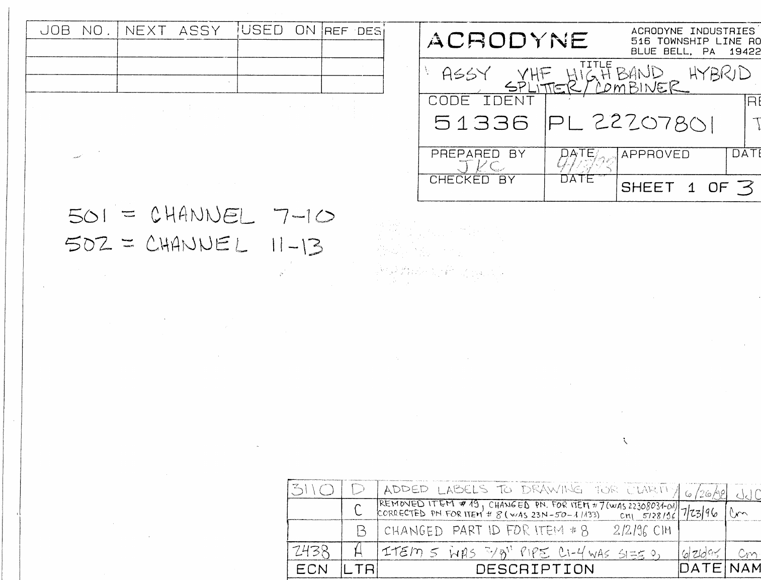
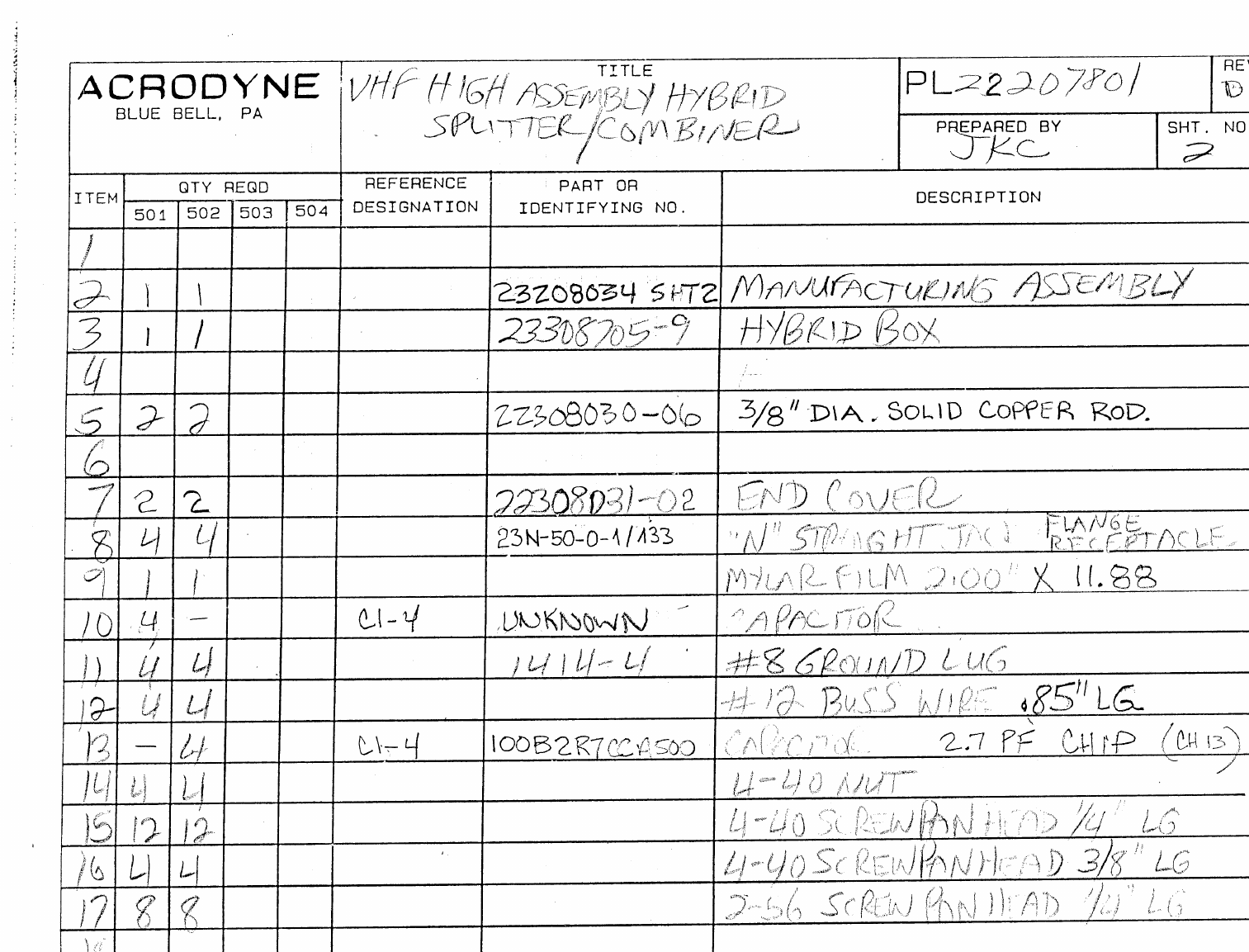
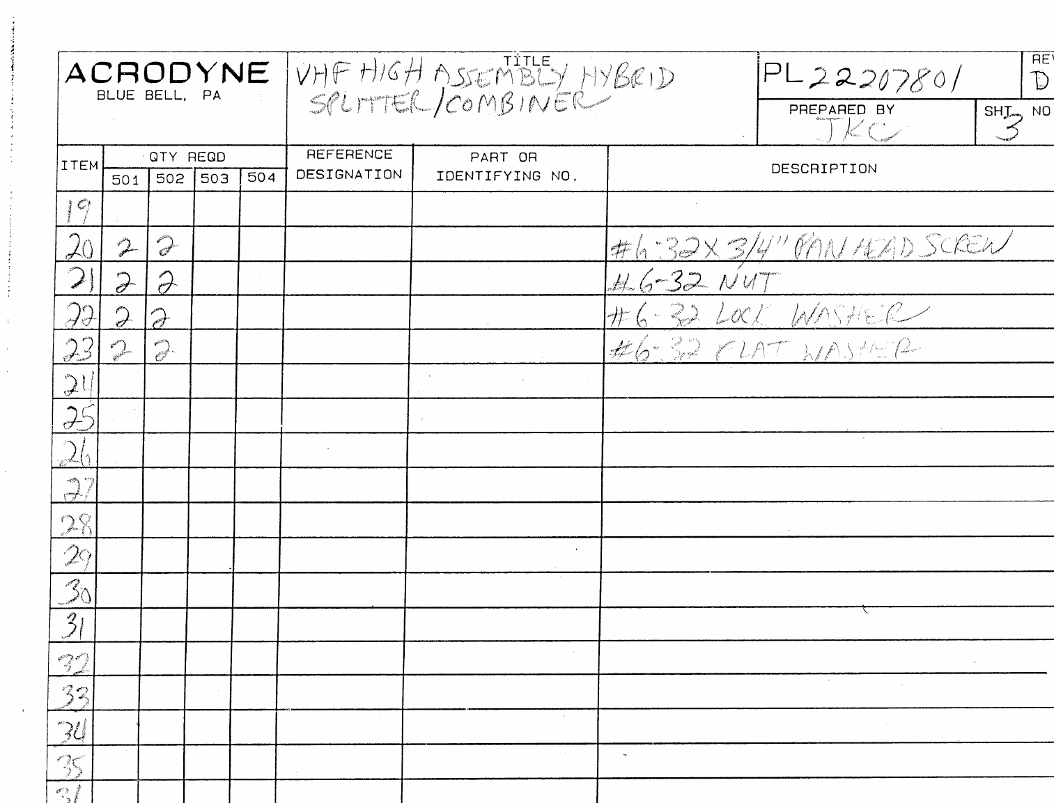
JOB NO.
NEXT ASSY.
USED ON
REF. DES.
23209084
23208743
ASSY
DESCRIPTION
501
WITH 5V PULL-UP RESISTORS.
502
W/OUT 5V PULL-UP RESISTORS.
503
SAME AS -502 WITH STRAIGHT TB1.
ECN LTR DESCRIPTION REVISED BY APPROVED BY
ACONVERTED TO CAD CSM
ACRODYNE INDUSTRIES
516 TOWNSHIP LINE ROAD
BLUE BELL, PA. 19422
TITLE
SOLID STATE AMP. CNTRL. CIRCUIT ASSEMBLY
CODE IDENT
51336 DOCUMENT NUMBER
PL22208858
REVISION
A
PREPARED BY
HFG
CHECKED BY
M.B.
DATE
10/94
DATE
12.94
APPROVED BY
M. BRICKER DATE
12/94
ACRODYNE
SHEET 1 OF 3

QUANTITY REQUIRED REFERENCE PART OR
ITEM -501 -502 -503 -504 DES. IDENTIFYING NUMBER DESCRIPTION VENDER
PL 22208858 rev A
ACRODYNE
BLUE BELL, PA
Title
SOLID STATE AMP. CNTRL.
CIRCUIT ASSEMBLY
.
PREPARED BY
HFG SHEET NO.
2
2
1X X X 22508959 SCHEMATIC
2
3 1 1 1 C1 199D106X0035DAI CAPACITOR: 10Uf, 35V TANT
4 1 1 1 C2 GRM42-
6C0G102J050BD
CHIP CAP
CAPACITOR: 0.001Uf
5 4 4 4 C3-6 GRM42-
6X7R104K050BL
CHIP CAP.
CAPACITOR: 0.1Uf
6
7 4 4 4 CR1,2,6
& 8 1N4007 DIODE
8 1 1 1 CR3 5082-4855 DIODE: LIGHT EMITTING, RED
9 2 2 2 CR4,5 5082-4950 DIODE: LIGHT EMITTING, GREEN
10 1 1 1 CR7 1N4749A DIODE: 24V, ZENER
11
12 3 3 3 FL1-3 DST310-55Y55-223M LOWPASS FILTER
13
14 1 1 1 Q1 2N3904 TRANSISTOR: NPN
15 1 1 1 Q2 2N3053 TRANSISTOR: NPN
16
17 1 1 1 R1 RC07GF113J RESISTOR: 11K OHM, 1/4W
18 1 1 1 R2 RC07GF202J RESISTOR: 2K OHM, 1/4W
19 1 1 1 R3 RC07GF751J RESISTOR: 750 OHM, 1/4W
20 1 1 1 R4 RC07GF272J RESISTOR: 2.7K OHM, 1/4W
21 1 1 1 R5 RC07GF104J RESISTOR: 100K OHM, 1/4W
22 3 3 3 R6,11,
& 12 RC07GF102J RESISTOR: 1K OHM, 1/4W
23 1 1 1 R7 RC07GF151J RESISTOR: 150 OHM, 1/4W
24 1 - - R8 RC20GF112J RESISTOR: 1100 OHM, 1/2W
25 1 - - R9 RC20GF751J RESISTOR: 750 OHM, 1/2W
26 1 1 1 R10 RC07GF821J RESISTOR: 820 OHM, 1/4W
27 1 1 1 R13 RC07GF103J RESISTOR: 10K OHM, 1/4W

QUANTITY REQUIRED REFERENCE PART OR
ITEM -501 -502 -503 -504 DES. IDENTIFYING NUMBER DESCRIPTION VENDER
PL 22208858 rev A
ACRODYNE
BLUE BELL, PA
Title
SOLID STATE AMP. CNTRL.
CIRCUIT ASSEMBLY
.
PREPARED BY
HFG SHEET NO.
3
3
28 1 1 1 R14 RC07GF152J RESISTOR: 1.5K OHM, 1/4W
29
30 1 1 1 S1 21606599 SWITCH: SPDT, PCB MOUNT (ON-OFF-ON)
31
32 3 3 -TB1 1733583 TERMINAL BLOCK: 3 POSITION (PHOENIX-45 DEG.)
33 - - 3TB1 1715734 TERMINAL BLOCK: 3 POSITION.
34
35 1 1 1 U1 LM311 IC: COMPARATOR WITH STROBE
36
37 1 1 1 22408859 PC BOARD
38 3 3 3 44F5289 LED SPACER
39 1 1 1 C8408-026 IC SOCKET: 8 PIN (U1)
40 4 4 4 350-1247-12-07-00 SPACER: 3/8” LONG, #4 CLEAR.
41
42
43
44
45
46
47
48
49
50
JOB NO.
NEXT ASSY.
USED ON
REF. DES.
223209084
TRH/500
24209082
TRH/500
ASSY
DESCRIPTION
-501
IPA METERING(2 SIDES)
-502
IPA METERING(1 SIDE) 100 Ω CURRENT LIMIT
-503
IPA METERING 10 Ω CURRENT LIMIT
-504
SINGLE AMP. METERING, 24211410
-505
IPA METERING(2 SIDES)
ECN LTR DESCRIPTION REVISED BY APPROVED BY
ADESCRIBED -501, -502. CSM 6/24/97 CSM 6/97
2967 BADDED -503 ASSY. HFG 9/26/97 MB 10/97
CADDED -504 ASSY. MTS 10/97 MB 10/97
3048 DADDED -505 ASSY. ADD ITEMS 17 - 21 PER ECN HFG 3/98
EREMOVED PIN PLACEMENT DWGS. 21309574 & ADDED INFO. TO PAGE 2 OF DWG. SMJ 4/99
FCHANGES TO DRAWING ONLY SMJ 5/99
ACRODYNE INDUSTRIES
516 TOWNSHIP LINE ROAD
BLUE BELL, PA. 19422
TITLE
ASSEMBLY,
UNIVERSAL SWITCH BOARD
CODE IDENT
51336 DOCUMENT NUMBER
PL22209040
REVISION
F
PREPARED BY
MTS
CHECKED BY
DATE
12/22/94
DATE
APPROVED BY
WFS DATE
6/14/97
ACRODYNE
SHEET 1 OF 2

QUANTITY REQUIRED REFERENCE PART OR
ITEM -501 -502 503 -504 -505 DES. IDENTIFYING NUMBER DESCRIPTION VENDER
PL 22209040 Rev F
ACRODYNE
BLUE BELL, PA
Title
ASSEMBLY, UNIVERSAL
SWITCH BOARD.
PREPARED BY
MTS SHEET NO.
2
1X X X X X 22509158 SCHEMATIC
2
3 1 - - 1 1 J1 65863-067 20 PIN HEADER
4 1 1 - - 1J2 65863-067 20 PIN HEADER
5
6 2 2 -2 2 R1,2 RC07GF5R6J RESISTOR, 5.6Ω, 1/4W
7 1 1 1 1 1 R3 RC07GF273J RESISTOR, 27KΩ, 1/4W
8 1 1 1 1 1 R4 3386P-1-103 RESISTOR, 10KΩ POT
9
10 1 1 1 1 1 S1 71BDF30-02-1-AJN SWITCH, ROTARY, 2P12T
11 1 1 1 1 1 S2 T201MH9AVBE SWITCH, RIGHT ANGLE, 5 W
12
13 1 1 1 1 1 TB1 1715734 TERMINAL BLOCK, 3 POSITION
14
15 1 1 1 1 1 22409039 PCB
16 2 2 2 2 2 21309109 BRACKET
17
18
19
20
21
22
23
24
25
26
27
28
29
30
31
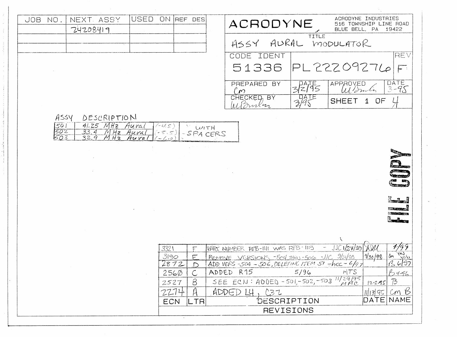
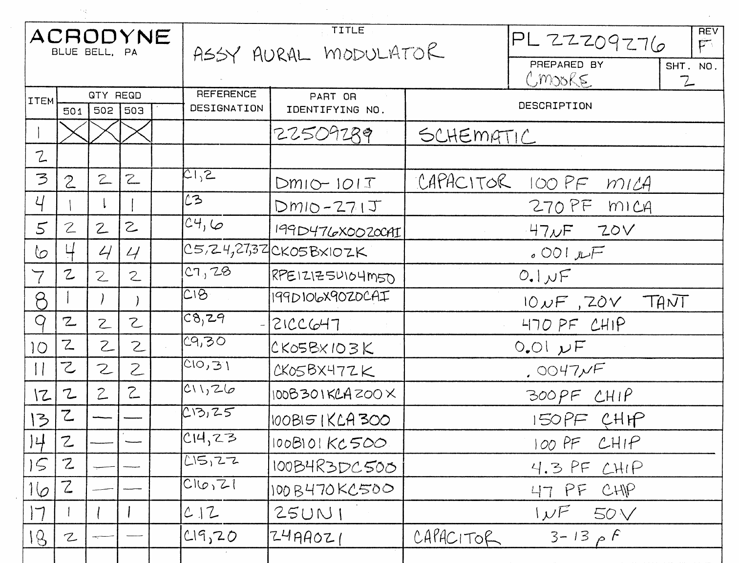
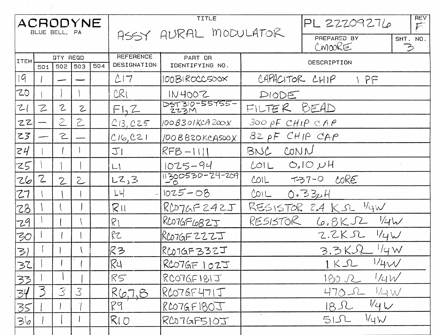
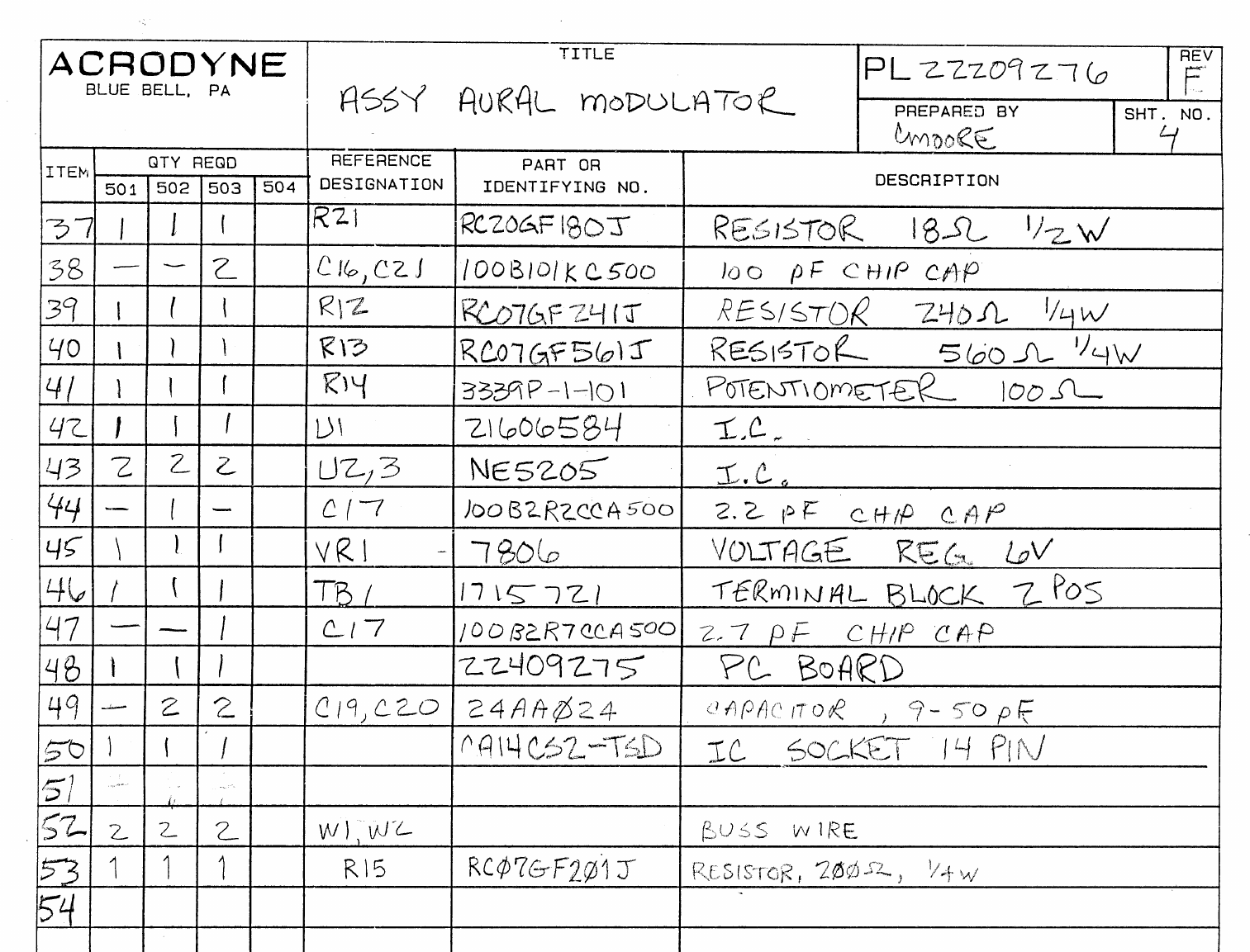
ASSY DESCRIPTION
-501 MMDS
-502 BROADCAST, NTSC-CONNECTOR
-503 BROADCAST, PAL-CONNECTOR
-504 BROADCAST, NTSC-CABLE
-505 BROADCAST, PAL-CABLE
NOTE: REVISIONS “E & F &G” ASSEMBLIES ONLY GOOD FOR REVISION “C” AND “D”ARTWORK.
ECN LTR DESCRIPTION REVISED BY APPROVED BY
A ADD -502, DELEATE J2, J3, ADD W1, W2, W3, W4 HFG 1/97 JB 1/97
B REVISED WHITE CLIPPER CIRCUIT HFG 2/97 JB 2/97
2818 C ADD -503, -504, AND -503, SEE ECN, CHANGED PL FORMAT HFG 5/97
2974 D SEE ECN WB 10/97
E SEE ECN’S 3059, 3063, 3074, 3099 WB 3/98 MB 3/98
F SEE E.C.N.’S #3245, 3262 JJC 11/06/98
3245 G SEE ECN #3245 MMC-11/30/98
ACRODYNE INDUSTRIES
516 TOWNSHIP LINE ROAD
BLUE BELL, PA. 19422
ACRODYNE
TITLE
ASSEMBLY: VIDEO AGC WITH BACK PORCH
CLAMP PC BOARD
CODE IDENT
51336
DOCUMENT NUMBER
PL22210886
REVISION
G
PREPARED BY
HFG
CHECKED BY
GCC
DATE
1/2/97
DATE
1/3/97
APPROVED BY
M. BRICKER DATE
6/98
SHEET 1 OF 5
JOB NUMBER NEXT ASSEMBLY USED ON REF. DES.

QUANTITY REQUIRED REFERENCE PART OR
ITEM -501 -502 -503 -504 -505 DESIGNATOR IDENTIFYING NUMBER DESCRIPTION VENDER
PL 22210886
REV G
ACRODYNE
BLUE BELL, PA
Title
ASSEMBLY: VIDEO AGC WITH
BACK PORCH CLAMP PC BOARD PREPARED BY
HFG SHEET NO.
2
XXXXX 22510887 SCHEMATIC VIDEO AGC WITH
BACK PORCH CLAMP
1 1 1 1 1 1 22410885 PC BOARD, VIDEO AGC WITH
BACK PORCH CLAMP
2
366666 CA8CS2-TSD SOCKET, IC 8 PIN (FOR
U1,2,3,4,6,9)
411111 CA14CS2-TSD SOCKET, IC 14 PIN (FOR K1)
511111 CA16CS2-TSD SOCKET, IC 16 PIN (FOR U8)
6-1111 H175C HOLDER, LED, R/A (BIVAR)
722222 175-6-240P PAD, HEAT TRANSFER, TO-220
822222 SCREW, PAN HEAD, #4-40 X 3/8”
LONG
922222 WASHER, LOCK, #4
1022222 NUT, HEX, #4-40
1123333 15-38-1024 JUMPER, 2 POSITION (FOR
-501 JP2, PINS 1 AND 2 OF JP3 ),
(FOR -502, -503, -504, -505
JP1, JP2, PINS 1 AND 2 OF JP3)
1222222BR1,2 DB105 DIODE BRIDGE
13 20 20 20 20 20 C1-8,11,17,18,23,
24,27,29,30,31,
33-35
GRM42-
6X7R104K050BL CAPACITOR, 0.1 uF, CHIP
1411111C9 24AA021 CAPACITOR, 2.8-12.5 pF,
VARIABLE
1511111C10 ULB1V100M CAPACITOR, 10 uF, 20V,
ELECTROLYTIC, RADIAL
16 - - 1-1C12 DM10-131J CAPACITOR, 130 pF, MICA
17 1 1 -1-C12 DM10-201J CAPACITOR, 200 pF, MICA
1822222C13,14 25VBSL470 CAPACITOR, 470 uF, 25V,
ELECTROLYTIC, RADIAL
1922222C15,16 108RLR010M CAPACITOR, 1000 uF, 10V,
ELECTROLYTIC, RADIAL

QUANTITY REQUIRED REFERENCE PART OR
ITEM -501 -502 -503 -504 -505 DESIGNATOR IDENTIFYING NUMBER DESCRIPTION VENDER
PL 22210886
REV G
ACRODYNE
BLUE BELL, PA
Title
ASSEMBLY: VIDEO AGC WITH
BACK PORCH CLAMP PC BOARD PREPARED BY
HFG SHEET NO.
3
2044444C19-22 GRM42-
6X7R102K050BL CAPACITOR, 0.001 uF, CHIP
2111111C25 DM15-911J CAPACITOR, 910 pF, MICA
2211111C26 CK05BX103K CAPACITOR, 0.01 uF, CERAMIC
2311111C28 199D226X0035EE2 CAPACITOR, 22 uF, 35V,
TANTALUM
2411111C32 DM10-430J CAPACITOR, 43 pF, MICA
2511111C36 199D105X0035AA1 CAPACITOR, 1 uF, 35V,
TANTALUM
2611111C37 199D474X9035AA1 CAPACITOR, 0.47 uF, 35V,
TANTALUM
2711111C38 199D225X0035BA1 CAPACITOR, 2.2 uF, 35V,
TANTALUM
2811111C39 199D475X0035CA1 CAPACITOR, 4.7 uF, 35V,
TANTALUM
2911111D1 5082-4950 LED (GREEN)
3022222D2,4 1N4007 DIODE, 100V, 1A
3111111D3 VTL5C7 DIODE, OPTO
3222222D5,9 1N5711 DIODE
3333333D8,10,11 1N4148A DIODE
34 -2 2 - - J1,4 RFB-1113-B CONNECTOR, BNC
35 -1111JP1 65507-436 HEADER, 2 POSITION
3611111JP2 65507-436 HEADER, 2 POSITION
3711111K1 HE721A0500 RELAY, 5V, SPST
3811111L1 1025-44 COIL, 10.0 uH
3922222L2,3 1025-20 COIL, 1.0 uH
40 1 1 -1-L4 1025-28 INDUCTOR, 2.2 uH
41 - - 1-1L4 1025-24 INDUCTOR, 1.5 uH
4211111L6 1025-60 COIL, 47.0 uH
4311111Q1 2N4392 TRANSISTOR, JFET, N-CHANNEL
4411111Q2 2N2907A TRANSISTOR, PNP
4511111Q3 2N3906 TRANSISTOR, PNP
4611111R1 RC07GF620J RESISTOR, 62 OHM, 1/4W, 5%
4711111R2 RC07GF150J RESISTOR, 15 OHM, 1/4W, 5%
4811111R3 RC07GF820J RESISTOR, 82 OHM, 1/4W, 5%
4944444R4,13,16,33 RC07GF511J RESISTOR, 510 OHM, 1/4W, 5%

QUANTITY REQUIRED REFERENCE PART OR
ITEM -501 -502 -503 -504 -505 DESIGNATOR IDENTIFYING NUMBER DESCRIPTION VENDER
PL 22210886
REV G
ACRODYNE
BLUE BELL, PA
Title
ASSEMBLY: VIDEO AGC WITH
BACK PORCH CLAMP PC BOARD PREPARED BY
HFG SHEET NO.
4
5022222R5,6 RC07GF4R7J RESISTOR, 4.7 OHM, 1/4W, 5%
5111111R7 RC07GF472J RESISTOR, 4.7K, 1/4W, 5%
5222222R8,12 RC07GF510J RESISTOR, 51 OHM, 1/4W, 5%
5322222R9,10 RC07GF102J RESISTOR, 1K, 1/4W, 5%
5433333R11,47,49 RC07GF104J RESISTOR, 100K, 1/4W, 5%
5533333R15,17,19 RC07GF101J RESISTOR, 100 OHM, 1/4W, 5%
5633333R20,34,44 RC07GF750J RESISTOR, 75 OHM, 1/4W, 5%
5711111R21 RC07GF301J RESISTOR, 300 OHM, 1/4W, 5%
5833333R22,23,45 RC07GF151J RESISTOR, 150 OHM, 1/4W, 5%
5933333R24,32,39 RC07GF181J RESISTOR, 180 OHM, 1/4W, 5%
6011111R25 RC07GF684J RESISTOR, 680K, 1/4W, 5%
6111111R26 RC07GF390J RESISTOR, 39 OHM, 1/4W, 5%
6211111R28 RC07GF121J RESISTOR, 120 OHM, 1/4W, 5%
6311111R29 RC07GF360J RESISTOR, 36 OHM, 1/4W, 5%
6422222R30,31 RC07GF201J RESISTOR, 200 OHM, 1/4W, 5%
6511111R41 RC07GF361J RESISTOR, 360 OHM, 1/4W, 5%
6611111R42 RC07GF241J RESISTOR, 240 OHM, 1/4W, 5%
6711111R46 RC07GF103J RESISTOR, 10K, 1/4W, 5%
6811111R48 RC07GF394J RESISTOR, 390K, 1/4W, 5%
6911111R50 RC07GF105J RESISTOR, 1M, 1/4W, 5%
7033333R37,38,40 SBT RESISTOR, SELECT BY TEST
7122222R14,36 3339P-1-101 POTENTIOMETER, 100 OHM
7222222R18,27 3386P-1-102 POTENTIOMETER, 1K, SQUARE
7311111R35 3339P-1-103 POTENTIOMETER, 10K
7411111R43 3339P-1-501 POTENTIOMETER, 500 OHM
7511111S1 T201MH9AVBE SWITCH, TOGGLE, DPDT
7611111S2 ASE22 SWITCH, SLIDE, DPDT
7722222TB1,(E1-E2) 1715721 TERMINAL BLOCK, 2 POS.
7811111TB2 1715734 TERMINAL BLOCK, 3 POS.
7911111T1 LP-20-300 TRANSFORMER
8055555U1,2,3,4,6 MAX404CPA IC, VIDEO OP-AMP
8111111U5 LM1881 IC, SYNC SEPARATOR
8211111U7 LT1227-CN8 IC, VIDEO OP-AMP
8311111U8 CD4046BCN IC, PHASE LOCKED LOOP
8411111U9 NE555 IC, TIMER

QUANTITY REQUIRED REFERENCE PART OR
ITEM -501 -502 -503 -504 -505 DESIGNATOR IDENTIFYING NUMBER DESCRIPTION VENDER
PL 22210886
REV G
ACRODYNE
BLUE BELL, PA
Title
ASSEMBLY: VIDEO AGC WITH
BACK PORCH CLAMP PC BOARD PREPARED BY
HFG SHEET NO.
5
8511111VR1 7805 VOLTAGE REGULATOR, +5V
8611111VR2 7905 VOLTAGE REGULATOR, -5V
87 2 ---2W1,4 23200165-5-U-35-21 CABLE ASSEMBLY, 21 INCH
88 2 ----W2,3 23200165-5-U-35-16 CABLE ASSEMBLY, 16 INCH
89 ---1-W1 23200165-5-U-35-24 CABLE ASSEMBLY, 24 INCH
90 ---1-W4 23200165-5-U-35-22 CABLE ASSEMBLY, 22 INCH
9111111JP3 65507-436 HEADER, 3 POSITION
92
JOB NO.
NEXT ASSY.
USED ON
REF. DES.
ASSY
DESCRIPTION
-501 NTSC M/N, 120VAC
-502 NTSC M/N, 240VAC
-503 PAL B/G, 120VAC
-504 PAL B/G, 240VAC
-505 VIDEO CORRECTOR ONLY, 120VAC
-506 VIDEO CORRECTOR ONLY, 240VAC
-507 VIDEO CORRECTOR ONLY, 120VAC
WITH RAL #7035 PANEL
-508 NTSC M/N, 120VAC WITH RAL #7035 PANEL
-509 NTSC M/N, 240VAC WITH RAL #7035 PANEL
ECN LTR DESCRIPTION REVISED BY APPROVED BY
-INITIAL RELEASE. RGD CSM: 08/20/98
AADDED -507 VERSION: RAL #7035 ON FRONT PANEL. KLL CSM: 01/07/99
BECN #3331, 3349, AND ADDED -508 & -509 ASSY’S, ITEM A2 WAS -502, AND #48 WAS
54B MTS: 02/25/99
ACRODYNE INDUSTRIES
516 TOWNSHIP LINE ROAD
BLUE BELL, PA. 19422
TITLE
CHASSIS ASSEMBLY:
VIDEO PROCESSOR
CODE IDENT
51336 DOCUMENT NUMBER
PL22211753-501 REVISION
B
PREPARED BY
R.G. DICKSON
CHECKED BY
DATE
01/30/98
DATE
APPROVED BY
DATE
ACRODYNE
SHEET 1 OF 3

QUANTITY REFERENCE PART OR
ITEM REQUIRED DESIGNATION IDENTIFYING NUMBER DESCRIPTION VENDER
PL22211753-501 REV. B
ACRODYNE
BLUE BELL, PA
Title
CHASSIS ASSEMBLY:
VIDEO PROCESSOR PREPARED BY
RGD SHEET NO.
2
1X22509321 WIRING DIAGRAM
2
3
41A1 23208695-501 ASSEMBLY, VIDEO CORRECTOR PCB
51A2 22210886-504 ASSEMBLY, VIDEO AGC PCB NT SC
61A3 22207131-501 ASSEMBLY, TRANSFORMER PCB, 615VAC
7
81F1 MDL1 FUSE, 120VAC
9
10 1FL1 6J4 FILTER, AC LINE FUSED CORCOM
11
12 1RV1 VP130LA10A VARISTOR, 130 VAC
13
14 1W1 23200165 -41-U-35 CABLE ASSY.
15 1W2 23200165 -41-U-41 CABLE ASSY.
16 1W3 23200165 -5-U-35 CABLE ASSY.
17 1W4 23200165 -41-U-35 CABLE ASSY.
18
19
20
21
22
23
24
25
26
27
28
29
30
31
32
33
34

QUANTITY REFERENCE PART OR
ITEM REQUIRED DESIGNATION IDENTIFYING NUMBER DESCRIPTION VENDER
PL22211753-501 REV. B
ACRODYNE
BLUE BELL, PA
Title
CHASSIS ASSEMBLY:
VIDEO PROCESSOR PREPARED BY
RGD SHEET NO.
3
35 1C-300-S-116 SLIDE (PAIR) 16 INCH GEN DEVICES.
36 2175-6-240P INSULATOR WAKEFIELD
37 23049K SHOULDER WASHER, MICA
38 122311733-01 DETAIL, COVER, TOP
39 1 22311734 DETAIL, BOTTOM
40 2 22311728 DETAIL, SIDE
41 1 22309318 DETAIL, U BRACKET
42 1 22311727 DETAIL, BACK
43 122309291-03 DETAIL, PANEL, FRONT
44
45 2B4-10-103-12 HANDLES SOUTHCO
46 2HDH-373 HEAT SINK WAKEFIELD
47 88159-B-0440 STANDOFF,
48 21414-4 GROUND LUG
49
50 12 SCREW, PAN HEAD, N0. 4-40 x 5/16” LONG
51 24 SCREW, FLAT HEAD, NO. 4-40 x 1/4” LONG
52 5NUT, HEX, NO. 4-40
53 17 WASHER, FLAT, NO. 4
54 17 WASHER, LOCK, NO. 4
55
56 6SCREW, PAN HEAD, NO. 6-32 x 3/8” LONG
57 2NUT, HEX, NO. 6-32
58 8WASHER, FLAT, NO. 6
59 8WASHER, SPLIT-LOCK, NO. 6
60
61 4SCREW, PAN HEAD, NO. 8-32 x 3/8” LONG
62 4SCREW, FLAT HEAD, NO.8-32 x 1/2” LONG
63
64 2NUT, HEX, NO. 10-32
65 2WASHER, FLAT, NO. 10
66 2WASHER, SPLIT-LOCK, NO. 10
67
JOB NO.
NEXT ASSY.
USED ON
REF. DES.
ASSY
DESCRIPTION
-501 45.75 VIS IF/3.58 COLOR +24VDC
-502 38.9 VIS IF/4.43 COLOR +24VDC
-503 45.75 VIS IF with -4.5 IM CORRECTOR +24VDC
-504 38.9 VIS IF with 5.5 IM CORRECTOR +24VDC
-505 45.75 VIS IF/3.58 COLOR +15VDC
-506 38.9 VIS IF/4.43 COLOR +15VDC
-507 45.75 VIS IF/3.58 COLOR +15VDC (RAL 7035)
-508 38.9 VIS IF/4.43 COLOR +15VDC (RAL 7035)
-509 45.75 VIS IF/3.58 COLOR +24VDC (RAL 7035)
ECN LTR DESCRIPTION REVISED BY APPROVED BY
-PRELIMINARY RELEASE DWM
ACHANGED 21209419 ASSEMBLY TO 21209419-503 JJC CSM 6/8/98
BADDED -505 & -506 ASSEMBLY KH MB 02/99
CADDED -507 AND -508 ASSEMBLY. MTS 02/12/9 DM 02/15/99
DADDED -509 ASSEMBLY. MTS 03/05/99
ACRODYNE INDUSTRIES
516 TOWNSHIP LINE ROAD
BLUE BELL, PA. 19422
TITLE
ASSEMBLY:
ASSEMBLY, IF PROCESSOR CHASSIS
CODE IDENT
51336 DOCUMENT NUMBER
PL 22211856-501 REVISION
D
PREPARED BY
DWM
CHECKED BY
CSM
DATE
5/18/98
DATE
5/24/98
APPROVED BY
M. BRICKER DATE
02/99
ACRODYNE
SHEET 1 OF 3

QUANTITY REQUIRED REFERENCE PART OR
ITEM -501 -502 -503 -504 DES. IDENTIFYING NUMBER DESCRIPTION VENDER
PL 22211856-501 Rev. D
ACRODYNE
BLUE BELL, PA
Title
ASSEMBLY
IF PROCESSOR CHASSIS PREPARED BY
DWM SHEET NO.
2
1X22511858 WIRING DIAGRAM
2X23712110 CONTROLS & INDICATORS
3
4 1 A1 23207637-503 ASSEMBLY, IF PRE CORRECTOR
5 1 A2 21209419-503 ASSEMBLY, VISION/SOUND COMBINER
6 1 A3 23210602-501 ASSEMBLY, IM/ICPM CORRECTOR
7 1 A4 23211632-501 ASSEMBLY, AURAL CORRECTOR
8 1 A5 22207958-503 ASSEMBLY, AMPLIFIER BUFFER
9 1 A6 22207295-501 ASSEMBLY, MINIATURE GAIN BLOCK
10
11 1 AT1 FP-50/SBT ATTENUATOR, 50 OHM, SBT dB, BNC
12
13
14
15
17
18
19
20
21 1PR C300-S-126 SLIDE, NON-PIVOTING, 26”
22 1 22309290-05 DETAIL, PANEL, FRONT
23 1 22309318-02 DETAIL, FRONT RAIL
24 1 22309466-01 DETAIL, SIDE RAIL, LEFT
25 1 22309466-02 DETAIL, SIDE RAIL, RIGHT
26 1 22309475-02 DETAIL, REAR RAIL
27 1 22311949 DETAIL, BOTTOM PLATE
28 1 22311950-01 DETAIL, TOP COVER
29 -22311950-02 DETAIL, TOP COVER
30 2 B4-10-103-12 HANDLE
31 5 8480 SPACER, ¼” DIA. X 1/8” LG.

QUANTITY REQUIRED REFERENCE PART OR
ITEM -501 -502 -503 -504 DES. IDENTIFYING NUMBER DESCRIPTION VENDER
PL 22211856-501 Rev. D
ACRODYNE
BLUE BELL, PA
Title
ASSEMBLY
IF PROCESSOR CHASSIS PREPARED BY
DWM SHEET NO.
3
32 36 #4-40 X ¼” LG. FLAT HD SCREW
33 15 #4-40 HEX NUT
34 19 #4 FLAT WASHER
35 19 #4 LOCK WASHER
36 4 #8-32 X 3/8” LG. FLAT HD. SCREW
37 2 #10-32 HEX NUT
38 2 #10 FLAT WASHER
39 2 #10 LOCK WASHER
40 2 #6-32 HEX NUT
41 2 #6 FLAT WASHER
42 2 #6 LOCK WASHER
43 14 #8-32 X ¼” LG.PAN HD SCREW
44 14 #8 FLAT WASHER
45 14 #8 LOCK WASHER
46 1 W3 23200165-5-L-41-11 COAX CABLE ASSEMBLY ( CONN. BRKT TO A2-E1)
47 2 E1,E2 54B TERMINAL STRIP
48 1 J81 206705-1 CONNECTOR, 9 PIN
50 2 #6-32 X ½” LG. FLAT HD SCREW
52 1 W1 23200165-35-L-5-28 COAX CABLE ASSEMBLY (J4 {COMBINED IF OUT} TO
A6-E4)
53 1 W2 23200165-5-L-41-8 COAX CABLE ASSEMBLY (A1 {IF INPUT} TO A2-J2)
54 1 W4 23200165-5-L-5-15 COAX CABLE ASSEMBLY (A1 {IF OUT} TO A6-E3)
55 1 W5 23200165-41-L-5-7 COAX CABLE ASSEMBLY (A3-J3 TO A5 {RF OUT})
56 1 W6 23200165-5-L-35-7 COAX CABLE ASSEMBLY (A5 {RF IN} TO A4-W1)
57 2 BRKT
1,2 22310667-02 BRACKET, CONNECTOR WITH PEM NUTS
58 -W3 23200165-5-L-5-11 COAX CABLE ASSEMBLY (A1 {IF OUT} TO A2-E1)
59 -W2 23200165-5-L-41-12 COAX CABLE ASSEMBLY (A1 {IF INPUT} TO AT1)
60 -W4 23200165-41-L-5-15 COAX CABLE ASSEMBLY (A2-J2 TO A6-E3)
ASSY DESCRIPTION
-501 SINGLE 4000W POWER SUPPLY
-502 DUAL 2000W POWER SUPPLY
-503 SINGLE 4000W POWER SUPPLY
WITH ISOLATION DIODE
ECN LTR DESCRIPTION REVISED BY APPROVED BY
3309 ADESIGN CHANGES, ADDED SHEET 3;
CHANGED BOM PER ECN 3309 MMC
AJG 12/98
ACRODYNE INDUSTRIES
516 TOWNSHIP LINE ROAD
BLUE BELL, PA. 19422
ACRODYNE
TITLE
ASSEMBLY: DC POWER SUPPLY FUSE AND
DISTRIBUTION PC BOARD
CODE IDENT
51336
DOCUMENT NUMBER
PL22212251
REVISION
A
PREPARED BY
W.BARONOFSKY
CHECKED BY
DATE
9/22/98
DATE
APPROVED BY
DATE
SHEET 1 OF 3
JOB NUMBER NEXT ASSEMBLY USED ON REF. DES.

QTY REQUIRED REFERENCE PART OR
ITEM -501 -502 -503 DESIGNATOR IDENTIFYING NUMBER DESCRIPTION VENDER
PL 22212251
REV A
ACRODYNE
BLUE BELL, PA
Title
ASSEMBLY: DC POWER SUPPLY
FUSE AND DISTRIBUTION
PC BOARD PREPARED BY
W.BARONOFSKY SHEET NO.
2
X22512250
SHEET 1 SCHEMATIC DIAGRAM, DC POWER SUPPLY FUSE
AND DISTRIBUTION PC BOARD
X22512250
SHEET 2 SCHEMATIC DIAGRAM, DC POWER SUPPLY FUSE
AND DISTRIBUTION PC BOARD
X22512250
SHEET 3 SCHEMATIC DIAGRAM, DC POWER SUPPLY FUSE
AND DISTRIBUTION PC BOARD
1 1 1 1 22412252 DC POWER SUPPLY FUSE AND DISTRIBUTION
PWB
2 4 4 4 D6-9 35BL505 LED, GREEN
3 4 4 4 D10-13 35BL504 LED, RED
4 4 4 4 D1,2,4,5 1N4148 DIODE, 1N4148
5-1 1 D3 MB2505 DIODE BRIDGE, 25 AMP
6 4 4 4 F3-6 ANN-40 FUSE, 40 AMP
7 1 -1F2 AGC-10 FUSE, 10 AMP 1 1/4 LONG x 1/4 DIA
8-2-F1,2 AGC-10 FUSE, 10 AMP 1 1/4 LONG x 1/4 DIA
9-3 2 WIRE, #18 AWG, THHN, RED, 2” LONG
10 12 12 12 R1-5,7,9,11,13-16 RC20GF202 RESISTOR, 2K OHM, 1/2W, 5%
11 4 4 4 R6,8,10,12 RC07GF820J RESISTOR, 82 OHM, 1/4W, 5%
12
13 7 7 7 TB1,2 1715734 TERMINAL BLOCK, 3 POSITION
14 2 4 2 44FH053 FUSE HOLDER, PC BOARD MOUNT
15 -1 1 SCREW, PAN HEAD, #10-32 x 7/8” LONG
16 -1 1 NUT, HEX. #10-32
17 -1 1 WASHER, LOCK, #10
18 -1 1 WASHER, FLAT, #10
19 8 8 8 SCREW, BRASS, ¼-20 x 1 LONG
20 16 16 16 NUT, HEX, BRASS, ¼-20
21 16 16 16 WASHER, BRASS, LOCK, ¼-20
22 12 12 12 WASHER, BRASS, FLAT, ¼-20
23 9 9 9 J1 02-06-7103 CONTACTS, FEMALE, PC TAIL MOLEX
24 1 1 1 J1 03-06-1092 CONNECTOR, RECEPTACLE, 9 POS MOLEX
25 A/R - - JP3 18 GA. BUSS WIRE, TINNED, WITH SLEEVING
26 1 -122213007-02 BUSS BAR, 4 POSITION
27 -2-22213007-01 BUSS BAR, 2 POSITION

QTY REQUIRED REFERENCE PART OR
ITEM -501 -502 -503 DESIGNATOR IDENTIFYING NUMBER DESCRIPTION VENDER
PL 22212251
REV A
ACRODYNE
BLUE BELL, PA
Title
ASSEMBLY: DC POWER SUPPLY
FUSE AND DISTRIBUTION
PC BOARD PREPARED BY
W.BARONOFSKY SHEET NO.
3
28 1 -1JP1 65507-436 HEADER, 2 POSITION
29 1 1 1 JP2 65507-436 HEADER, 3 POSITION
30 2 -215-38-1024 JUMPER 2 POSITION (FOR JP1,JP2)
31 -1-15-38-1024 JUMPER 2 POSITION (FOR JP2)
32 1 1 1 E1 GRD PAN HEAD SCREW, BRASS, #8-32 x ¾ LONG
33 1 1 1 E1 GRD HEX NUT, BRASS, #8-32

JOB NO.
NEXT ASSY.
USED ON
REF. DES.
ASSY
DESCRIPTION
-501 SINGLE 4000W POWER SUPPLY {HC40-C1034}
-502 DUAL 2000W POWER SUPPLY {2 x HC20-C1164}
-503 DUAL 2000W POWER SUPPLY {2 x ECT21-C1020}
-504 SINGLE 4000W POWER SUPPLY
WITH ISOLATION DIODE {HC4011-C12243}
{HC2011-C1370}
-505 FN6000 P.S. {2 x FN6000}
-506 A -504 ASSEMBLY WITH SLIDE LATCH KIT ON THE
PS1-P1 END.
-507 DUAL 2000W POWER SUPPLY (2xEJN-6000)
ECN LTR DESCRIPTION REVISED BY APPROVED BY
-INITIAL RELEASE. 08/20/98 W.B. MB: 01/99
3328 ANUMEROUS CHANGES PER ECN. 03/11/99 MTS DWM 04/26/99
BADDED -506 & 507 ASSEMBLYS. 04/26/99 MTS
ACRODYNE INDUSTRIES
516 TOWNSHIP LINE ROAD
BLUE BELL, PA. 19422
TITLE:
CABLE ASSEMBLY:
FOR USE WITH DC POWER SUPPLY FUSE AND DISTRIBUTION PCB
CODE IDENT
51336 DOCUMENT NUMBER
PL22212570-501 REVISION
B
PREPARED BY
W. Baronofsky
CHECKED BY
DATE
08/20/98
DATE
APPROVED BY
M. Bricker DATE
01/99
ACRODYNE
SHEET 1 OF 2

QUAN. REFERENCE PART OR
ITEM REQD. DESIGNATION IDENTIFYING NUMBER DESCRIPTION VENDER
PL22212570-501 REV: B
ACRODYNE
BLUE BELL, PA
Title
CABLE ASSEMBLY:
FOR USE WITH DC POWER SUPPLY FUSE AND
DISTRIBUTION PCB
PREPARED BY
W. Baronofsky SHEET NO.
2
11P1 03-06-2092 CONNECTOR, PLUG, 9 POS MOLEX
2802-06-2103 CONTACTS, MALE FOR P1 MOLEX
31PS1-P1 745496-2 CONNECTOR, PLUG, 25 POS. SUB-D
4-PS1-P1, PS2-P1 745496-2 CONNECTOR, PLUG, 25 POS. SUB-D
51W1 WIRE, #22 AWG, THHN, BRN
61W2 WIRE, #22 AWG, THHN, RED
71W3 WIRE, #22 AWG, THHN, ORG
81W4 WIRE, #22 AWG, THHN, YEL
9-W1,5 WIRE, #22 AWG, THHN, BRN
10 -W2,6 WIRE, #22 AWG, THHN, RED
11 -W3,7 WIRE, #22 AWG, THHN, ORG
12 -W4,8 WIRE, #22 AWG, THHN, YEL
13 -P1,PS1-P1, PS1-P2,
PS2-P1,PS2-P2 03-06-2092 CONNECTOR, PLUG, 9 POS MOLEX
14 -02-06-2103 CONTACTS, MALE FOR P1,PS1-P1,
PS1-P2, PS2-P1, PS2-P2 MOLEX
15 -PS1-P1, PS2-P1 39-01-2125 CONNECTOR, PLUG, 12 POS. MOLEX
16 -39-00-0039 CONTACTS, MALE FOR PS1-P1, PS2-P1 MOLEX
17
18 1749626-2 BACK SHELL (FOR PS1-P1)
19 -749626-2 BACK SHELL (FOR PS1-P1 & PS2-P1)
20
21
22
23
24
25
26
27
28
29
30
31

JOB NO.
NEXT ASSY.
USED ON
REF. DES.
ASSY
DESCRIPTION
-501 SINGLE 4000W POWER SUPPLY {HC40-C1034}
-502 DUAL 2000W POWER SUPPLY {2 x HC20-C1164}
-503 DUAL 2000W POWER SUPPLY {2 x ECT21-C1020}
-504 SINGLE 4000W POWER SUPPLY
WITH ISOLATION DIODE {HC4011-C12243}
{HC2011-C1370}
505 FN6000 P.S. {2 x FN6000}
-506 A -504 ASSEMBLY WITH SLIDE LATCH KIT ON THE
PS1-P1 END.
-507 DUAL 2000W POWER SUPPLY (2xEJN-6000)
ECN LTR DESCRIPTION REVISED BY APPROVED BY
-INITIAL RELEASE. 08/20/98 W.B. MB: 01/99
3328 ANUMEROUS CHANGES PER ECN. 03/11/99 MTS DWM 04/26/99
BADDED -506 & 507 ASSEMBLYS. 04/26/99 MTS
ACRODYNE INDUSTRIES
516 TOWNSHIP LINE ROAD
BLUE BELL, PA. 19422
TITLE:
CABLE ASSEMBLY:
FOR USE WITH DC POWER SUPPLY FUSE AND DISTRIBUTION PCB
CODE IDENT
51336 DOCUMENT NUMBER
PL22212570-502 REVISION
B
PREPARED BY
W. Baronofsky
CHECKED BY
DATE
08/20/98
DATE
APPROVED BY
M. Bricker DATE
01/99
ACRODYNE
SHEET 1 OF 2

QUAN. REFERENCE PART OR
ITEM REQD. DESIGNATION IDENTIFYING NUMBER DESCRIPTION VENDER
PL22212570-502 REV: B
ACRODYNE
BLUE BELL, PA
Title
CABLE ASSEMBLY:
FOR USE WITH DC POWER SUPPLY FUSE AND
DISTRIBUTION PCB
PREPARED BY
W. Baronofsky SHEET NO.
2
1-P1 03-06-2092 CONNECTOR, PLUG, 9 POS MOLEX
2-02-06-2103 CONTACTS, MALE FOR P1 MOLEX
3-PS1-P1 745496-2 CONNECTOR, PLUG, 25 POS. SUB-D
4-PS1-P1, PS2-P1 745496-2 CONNECTOR, PLUG, 25 POS. SUB-D
5-W1 WIRE, #22 AWG, THHN, BRN
6-W2 WIRE, #22 AWG, THHN, RED
7-W3 WIRE, #22 AWG, THHN, ORG
8-W4 WIRE, #22 AWG, THHN, YEL
92W1,5 WIRE, #22 AWG, THHN, BRN
10 2W2,6 WIRE, #22 AWG, THHN, RED
11 2W3,7 WIRE, #22 AWG, THHN, ORG
12 2W4,8 WIRE, #22 AWG, THHN, YEL
13 5P1,PS1-P1, PS1-P2,
PS2-P1,PS2-P2 03-06-2092 CONNECTOR, PLUG, 9 POS MOLEX
14 16 02-06-2103 CONTACTS, MALE FOR P1,PS1-P1,
PS1-P2, PS2-P1, PS2-P2 MOLEX
15 -PS1-P1, PS2-P1 39-01-2125 CONNECTOR, PLUG, 12 POS. MOLEX
16 -39-00-0039 CONTACTS, MALE FOR PS1-P1, PS2-P1 MOLEX
17
18 -749626-2 BACK SHELL (FOR PS1-P1)
19 -749626-2 BACK SHELL (FOR PS1-P1 & PS2-P1)
20
21
22
23
24
25
26
27
28
29
30
31

JOB NO.
NEXT ASSY.
USED ON
REF. DES.
ASSY
DESCRIPTION
-501 SINGLE 4000W POWER SUPPLY {HC40-C1034}
-502 DUAL 2000W POWER SUPPLY {2 x HC20-C1164}
-503 DUAL 2000W POWER SUPPLY {2 x ECT21-C1020}
-504 SINGLE 4000W POWER SUPPLY
WITH ISOLATION DIODE {HC4011-C12243}
{HC2011-C1370}
505 FN6000 P.S. {2 x FN6000}
-506 A -504 ASSEMBLY WITH SLIDE LATCH KIT ON THE
PS1-P1 END.
-507 DUAL 2000W POWER SUPPLY (2xEJN-6000)
ECN LTR DESCRIPTION REVISED BY APPROVED BY
-INITIAL RELEASE. 08/20/98 W.B. MB: 01/99
3328 ANUMEROUS CHANGES PER ECN. 03/11/99 MTS DWM 04/26/99
BADDED -506 & 507 ASSEMBLYS. 04/26/99 MTS
ACRODYNE INDUSTRIES
516 TOWNSHIP LINE ROAD
BLUE BELL, PA. 19422
TITLE:
CABLE ASSEMBLY:
FOR USE WITH DC POWER SUPPLY FUSE AND DISTRIBUTION PCB
CODE IDENT
51336 DOCUMENT NUMBER
PL22212570-503 REVISION
B
PREPARED BY
W. Baronofsky
CHECKED BY
DATE
08/20/98
DATE
APPROVED BY
M. Bricker DATE
01/99
ACRODYNE
SHEET 1 OF 2

QUAN. REFERENCE PART OR
ITEM REQD. DESIGNATION IDENTIFYING NUMBER DESCRIPTION VENDER
PL22212570-503 REV: B
ACRODYNE
BLUE BELL, PA
Title
CABLE ASSEMBLY:
FOR USE WITH DC POWER SUPPLY FUSE AND
DISTRIBUTION PCB
PREPARED BY
W. Baronofsky SHEET NO.
2
11P1 03-06-2092 CONNECTOR, PLUG, 9 POS MOLEX
2802-06-2103 CONTACTS, MALE FOR P1 MOLEX
3-PS1-P1 745496-2 CONNECTOR, PLUG, 25 POS. SUB-D
42PS1-P1, PS2-P1 745496-2 CONNECTOR, PLUG, 25 POS. SUB-D
5-W1 WIRE, #22 AWG, THHN, BRN
6-W2 WIRE, #22 AWG, THHN, RED
7-W3 WIRE, #22 AWG, THHN, ORG
8-W4 WIRE, #22 AWG, THHN, YEL
92W1,5 WIRE, #22 AWG, THHN, BRN
10 2W2,6 WIRE, #22 AWG, THHN, RED
11 2W3,7 WIRE, #22 AWG, THHN, ORG
12 2W4,8 WIRE, #22 AWG, THHN, YEL
13 -P1,PS1-P1, PS1-P2,
PS2-P1,PS2-P2 03-06-2092 CONNECTOR, PLUG, 9 POS MOLEX
14 -02-06-2103 CONTACTS, MALE FOR P1,PS1-P1,
PS1-P2, PS2-P1, PS2-P2 MOLEX
15 -PS1-P1, PS2-P1 39-01-2125 CONNECTOR, PLUG, 12 POS. MOLEX
16 -39-00-0039 CONTACTS, MALE FOR PS1-P1, PS2-P1 MOLEX
17
18 -749626-2 BACK SHELL (FOR PS1-P1)
19 2749626-2 BACK SHELL (FOR PS1-P1 & PS2-P1)
20
21
22
23
24
25
26
27
28
29
30
31

JOB NO.
NEXT ASSY.
USED ON
REF. DES.
ASSY
DESCRIPTION
-501 SINGLE 4000W POWER SUPPLY {HC40-C1034}
-502 DUAL 2000W POWER SUPPLY {2 x HC20-C1164}
-503 DUAL 2000W POWER SUPPLY {2 x ECT21-C1020}
-504 SINGLE 4000W POWER SUPPLY
WITH ISOLATION DIODE {HC4011-C12243}
{HC2011-C1370}
-505 FN6000 P.S. {2 x FN6000}
-506 A -504 ASSEMBLY WITH SLIDE LATCH KIT ON THE
PS1-P1 END.
-507 DUAL 2000W POWER SUPPLY (2xEJN-6000)
ECN LTR DESCRIPTION REVISED BY APPROVED BY
-INITIAL RELEASE. 08/20/98 W.B. MB: 01/99
3328 ANUMEROUS CHANGES PER ECN. 03/11/99 MTS DWM 04/26/99
BADDED -506 & 507 ASSEMBLYS. 04/26/99 MTS
ACRODYNE INDUSTRIES
516 TOWNSHIP LINE ROAD
BLUE BELL, PA. 19422
TITLE:
CABLE ASSEMBLY:
FOR USE WITH DC POWER SUPPLY FUSE AND DISTRIBUTION PCB
CODE IDENT
51336 DOCUMENT NUMBER
PL22212570-504 REVISION
B
PREPARED BY
W. Baronofsky
CHECKED BY
DATE
08/20/98
DATE
APPROVED BY
M. Bricker DATE
01/99
ACRODYNE
SHEET 1 OF 2

QUAN. REFERENCE PART OR
ITEM REQD. DESIGNATION IDENTIFYING NUMBER DESCRIPTION VENDER
PL22212570-504 REV: A
ACRODYNE
BLUE BELL, PA
Title
CABLE ASSEMBLY:
FOR USE WITH DC POWER SUPPLY FUSE AND
DISTRIBUTION PCB
PREPARED BY
W. Baronofsky SHEET NO.
2
11P1 03-06-2092 CONNECTOR, PLUG, 9 POS MOLEX
2802-06-2103 CONTACTS, MALE FOR P1 MOLEX
31PS1-P1 745496-2 CONNECTOR, PLUG, 25 POS. SUB-D
4-PS1-P1, PS2-P1 745496-2 CONNECTOR, PLUG, 25 POS. SUB-D
51W1 WIRE, #22 AWG, THHN, BRN
61W2 WIRE, #22 AWG, THHN, RED
71W3 WIRE, #22 AWG, THHN, ORG
81W4 WIRE, #22 AWG, THHN, YEL
9-W1,5 WIRE, #22 AWG, THHN, BRN
10 -W2,6 WIRE, #22 AWG, THHN, RED
11 -W3,7 WIRE, #22 AWG, THHN, ORG
12 -W4,8 WIRE, #22 AWG, THHN, YEL
13 -P1,PS1-P1, PS1-P2,
PS2-P1,PS2-P2 03-06-2092 CONNECTOR, PLUG, 9 POS MOLEX
14 -02-06-2103 CONTACTS, MALE FOR P1,PS1-P1,
PS1-P2, PS2-P1, PS2-P2 MOLEX
15 -PS1-P1, PS2-P1 39-01-2125 CONNECTOR, PLUG, 12 POS. MOLEX
16 -39-00-0039 CONTACTS, MALE FOR PS1-P1, PS2-P1 MOLEX
17
18 1749626-2 BACK SHELL (FOR PS1-P1)
19 -749626-2 BACK SHELL (FOR PS1-P1 & PS2-P1)
20
21
22
23
24
25
26
27
28
29
30

JOB NO.
NEXT ASSY.
USED ON
REF. DES.
ASSY
DESCRIPTION
-501 SINGLE 4000W POWER SUPPLY {HC40-C1034}
-502 DUAL 2000W POWER SUPPLY {2 x HC20-C1164}
-503 DUAL 2000W POWER SUPPLY {2 x ECT21-C1020}
-504 SINGLE 4000W POWER SUPPLY
WITH ISOLATION DIODE {HC4011-C12243}
{HC2011-C1370}
505 FN6000 P.S. {2 x FN6000}
-506 A -504 ASSEMBLY WITH SLIDE LATCH KIT ON THE
PS1-P1 END.
-507 DUAL 2000W POWER SUPPLY (2xEJN-6000)
ECN LTR DESCRIPTION REVISED BY APPROVED BY
-INITIAL RELEASE. 08/20/98 W.B. MB: 01/99
3328 ANUMEROUS CHANGES PER ECN. 03/11/99 MTS DWM 04/26/99
BADDED -506 & 507 ASSEMBLYS. 04/26/99 MTS
ACRODYNE INDUSTRIES
516 TOWNSHIP LINE ROAD
BLUE BELL, PA. 19422
TITLE:
CABLE ASSEMBLY:
FOR USE WITH DC POWER SUPPLY FUSE AND DISTRIBUTION PCB
CODE IDENT
51336 DOCUMENT NUMBER
PL22212570-505 REVISION
B
PREPARED BY
W. Baronofsky
CHECKED BY
DATE
08/20/98
DATE
APPROVED BY
M. Bricker DATE
01/99
ACRODYNE
SHEET 1 OF 2

QUAN. REFERENCE PART OR
ITEM REQD. DESIGNATION IDENTIFYING NUMBER DESCRIPTION VENDER
PL22212570-505 REV: A
ACRODYNE
BLUE BELL, PA
Title
CABLE ASSEMBLY:
FOR USE WITH DC POWER SUPPLY FUSE AND
DISTRIBUTION PCB
PREPARED BY
W. Baronofsky SHEET NO.
2
11P1 03-06-2092 CONNECTOR, PLUG, 9 POS MOLEX
2802-06-2103 CONTACTS, MALE FOR P1 MOLEX
3-PS1-P1 745496-2 CONNECTOR, PLUG, 25 POS. SUB-D
4-PS1-P1, PS2-P1 745496-2 CONNECTOR, PLUG, 25 POS. SUB-D
5-W1 WIRE, #22 AWG, THHN, BRN
6-W2 WIRE, #22 AWG, THHN, RED
7-W3 WIRE, #22 AWG, THHN, ORG
8-W4 WIRE, #22 AWG, THHN, YEL
92W1,5 WIRE, #22 AWG, THHN, BRN
10 2W2,6 WIRE, #22 AWG, THHN, RED
11 2W3,7 WIRE, #22 AWG, THHN, ORG
12 2W4,8 WIRE, #22 AWG, THHN, YEL
13 -P1,PS1-P1, PS1-P2,
PS2-P1,PS2-P2 03-06-2092 CONNECTOR, PLUG, 9 POS MOLEX
14 -02-06-2103 CONTACTS, MALE FOR P1,PS1-P1,
PS1-P2, PS2-P1, PS2-P2 MOLEX
15 2PS1-P1, PS2-P1 39-01-2125 CONNECTOR, PLUG, 12 POS. MOLEX
16 839-00-0039 CONTACTS, MALE FOR PS1-P1, PS2-P1 MOLEX
17
18 -749626-2 BACK SHELL (FOR PS1-P1)
19 -749626-2 BACK SHELL (FOR PS1-P1 & PS2-P1)
20
21
22
23
24
25
26
27
28
29
30
31
JOB NO.
NEXT ASSY.
USED ON
REF. DES.
ASSY
DESCRIPTION
-501 SINGLE 4000W POWER SUPPLY {HC40-C1034}
-502 DUAL 2000W POWER SUPPLY {2 x HC20-C1164}
-503 DUAL 2000W POWER SUPPLY {2 x ECT21-C1020}
-504 SINGLE 4000W POWER SUPPLY
WITH ISOLATION DIODE {HC4011-C12243}
{HC2011-C1370}
-505 FN6000 P.S. {2 x FN6000}
-506 A -504 ASSEMBLY WITH SLIDE LATCH KIT ON THE
PS1-P1 END.
-507 DUAL 2000W POWER SUPPLY (2xEJN-6000)
ECN LTR DESCRIPTION REVISED BY APPROVED BY
-INITIAL RELEASE. 08/20/98 W.B. MB: 01/99
3328 ANUMEROUS CHANGES PER ECN. 03/11/99 MTS DWM 04/26/99
BADDED -506 ASSEMBLY. 04/26/99 MTS DWM 04/26/99
BADDED -506 & 507 ASSEMBLYS. 04/26/99 MTS
ACRODYNE INDUSTRIES
516 TOWNSHIP LINE ROAD
BLUE BELL, PA. 19422
TITLE:
CABLE ASSEMBLY:
FOR USE WITH DC POWER SUPPLY FUSE AND DISTRIBUTION PCB
CODE IDENT
51336 DOCUMENT NUMBER
PL22212570-506 REVISION
B
PREPARED BY
W. Baronofsky
CHECKED BY
DATE
08/20/98
DATE
APPROVED BY
M. Bricker DATE
01/99
ACRODYNE
SHEET 1 OF 2

QUAN. REFERENCE PART OR
ITEM REQD. DESIGNATION IDENTIFYING NUMBER DESCRIPTION VENDER
PL22212570-506 REV: B
ACRODYNE
BLUE BELL, PA
Title
CABLE ASSEMBLY:
FOR USE WITH DC POWER SUPPLY FUSE AND
DISTRIBUTION PCB
PREPARED BY
W. Baronofsky SHEET NO.
2
11P1 03-06-2092 CONNECTOR, PLUG, 9 POS MOLEX
2802-06-2103 CONTACTS, MALE FOR P1 MOLEX
31PS1-P1 745496-2 CONNECTOR, PLUG, 25 POS. SUB-D
4-PS1-P1, PS2-P1 745496-2 CONNECTOR, PLUG, 25 POS. SUB-D
51W1 WIRE, #22 AWG, THHN, BRN
61W2 WIRE, #22 AWG, THHN, RED
71W3 WIRE, #22 AWG, THHN, ORG
81W4 WIRE, #22 AWG, THHN, YEL
9-W1,5 WIRE, #22 AWG, THHN, BRN
10 -W2,6 WIRE, #22 AWG, THHN, RED
11 -W3,7 WIRE, #22 AWG, THHN, ORG
12 -W4,8 WIRE, #22 AWG, THHN, YEL
13 -P1,PS1-P1, PS1-P2,
PS2-P1,PS2-P2 03-06-2092 CONNECTOR, PLUG, 9 POS MOLEX
14 -02-06-2103 CONTACTS, MALE FOR P1,PS1-P1,
PS1-P2, PS2-P1, PS2-P2 MOLEX
15 -PS1-P1, PS2-P1 39-01-2125 CONNECTOR, PLUG, 12 POS. MOLEX
16 -39-00-0039 CONTACTS, MALE FOR PS1-P1, PS2-P1 MOLEX
17
18 1749626-2 BACK SHELL (FOR PS1-P1)
19 -749626-2 BACK SHELL (FOR PS1-P1 & PS2-P1)
20 1745584-3 SLIDE LATCH KIT
21
22
23
24
25
26
27
28
29
30
JOB NO.
NEXT ASSY.
USED ON
REF. DES.
ASSY
DESCRIPTION
-501 SINGLE 4000W POWER SUPPLY {HC40-C1034}
-502 DUAL 2000W POWER SUPPLY {2 x HC20-C1164}
-503 DUAL 2000W POWER SUPPLY {2 x ECT21-C1020}
-504 SINGLE 4000W POWER SUPPLY
WITH ISOLATION DIODE {HC4011-C12243}
{HC2011-C1370}
505 FN6000 P.S. {2 x FN6000}
-506 A -504 ASSEMBLY WITH SLIDE LATCH KIT ON THE
PS1-P1 END.
-507 DUAL 2000W POWER SUPPLY (2xEJN-6000)
ECN LTR DESCRIPTION REVISED BY APPROVED BY
-INITIAL RELEASE. 08/20/98 W.B. MB: 01/99
3328 ANUMEROUS CHANGES PER ECN. 03/11/99 MTS DWM 04/26/99
BADDED -506 & 507 ASSEMBLYS. 04/26/99 MTS
ACRODYNE INDUSTRIES
516 TOWNSHIP LINE ROAD
BLUE BELL, PA. 19422
TITLE:
CABLE ASSEMBLY:
FOR USE WITH DC POWER SUPPLY FUSE AND DISTRIBUTION PCB
CODE IDENT
51336 DOCUMENT NUMBER
PL22212570-507 REVISION
B
PREPARED BY
W. Baronofsky
CHECKED BY
DATE
08/20/98
DATE
APPROVED BY
M. Bricker DATE
01/99
ACRODYNE
SHEET 1 OF 2

QUAN. REFERENCE PART OR
ITEM REQD. DESIGNATION IDENTIFYING NUMBER DESCRIPTION VENDER
PL22212570-507 REV: B
ACRODYNE
BLUE BELL, PA
Title
CABLE ASSEMBLY:
FOR USE WITH DC POWER SUPPLY FUSE AND
DISTRIBUTION PCB
PREPARED BY
W. Baronofsky SHEET NO.
2
11P1 03-06-1092 CONNECTOR, PLUG, 9 POS. MOLEX
2-02-06-2103 CONTACTS, MALE FOR P1 MOLEX
3-PS1-P1 745496-2 CONNECTOR, PLUG, 25 POS. SUB-D
4-PS1-P1, PS2-P1 745496-2 CONNECTOR, PLUG, 25 POS. SUB-D
5-W1 WIRE, #22 AWG, THHN, BRN
6-W2 WIRE, #22 AWG, THHN, RED
7-W3 WIRE, #22 AWG, THHN, ORG
8-W4 WIRE, #22 AWG, THHN, YEL
92W1,5 WIRE, #22 AWG, THHN, BRN
10 2W2,6 WIRE, #22 AWG, THHN, RED
11 2W3,7 WIRE, #22 AWG, THHN, ORG
12 2W4,8 WIRE, #22 AWG, THHN, YEL
13 2PS1-P1, PS2-P1 03-06-2061 CONNECTOR, PLUG, 6 POS. MOLEX
14 16 02-06-2103 CONTACTS, MALE FOR P1,PS1-P1,
PS1-P2, PS2-P1, PS2-P2 MOLEX
15 -PS1-P1, PS2-P1 39-01-2125 CONNECTOR, PLUG, 12 POS. MOLEX
16 -39-00-0039 CONTACTS, MALE FOR PS1-P1, PS2-P1 MOLEX
17
18 -749626-2 BACK SHELL (FOR PS1-P1)
19 -749626-2 BACK SHELL (FOR PS1-P1 & PS2-P1)
20
21
22
23
24
25
26
27
28
29
30
31
JOB NO.
NEXT ASSY.
USED ON
REF. DES.
99091
CH 7
TTI INC
ASSY
DESCRIPTION
-501
Channel 7
ECN LTR DESCRIPTION REVISED BY APPROVED BY
-Initial Release for Customer Review hcc - 3/22/99 MB - 3/23/99
AOn Drawing, Electrical Characteristics change per Customer hcc - 3/30/99 MB - 3/30/99
BAdd Cabinet Assy #; Items 4 & 6 Deleted, Modify Drawing to reflect ‘As Built’ hcc - 5/19/99
ACRODYNE INDUSTRIES
516 TOWNSHIP LINE ROAD
BLUE BELL, PA. 19422
TITLE
APPLICATION DRAWING,TRH/1KE
CODE IDENT
51336 DOCUMENT NUMBER
PL22613202
REVISION
B
PREPARED BY
hcc
CHECKED BY
Bricker
DATE
3/22/99
DATE
3/99
APPROVED BY DATE
ACRODYNE
SHEET 1 OF 2

QUANTITY REQUIRED REFERENCE PART OR
ITEM -501 -502 -503 -504 DES. IDENTIFYING NUMBER DESCRIPTION VENDER
PL 22613202 rev B
ACRODYNE
BLUE BELL, PA
Title
APPLICATION DRAWING
TRH/1KE PREPARED BY
hcc SHEET NO.
2
2
1
2 1 A1 22111237-502 Assembly, TRH/1KE Cabinet, Channel 7 ACRO
3
4
5
6
7
8
9
10 1 21113110-99091 Accessory Kit ACRO
11
12 1 NPN Vendor & Test Data
13 2 NPN Instruction Manual Set
14
15
16
17
18
19
20
21
22
23
24
25
JOB NO.
NEXT ASSY.
USED ON
REF. DES.
24103987
TRH/10KA
ASSY
DESCRIPTION
-501 VHF HIGH 7 - 13 (PLUG-IN)
-502 VHF LOW 2-6 (PLUG-IN)
-503 TRAY STYLE HIGH 7 - 13
-504 TRAY STYLE LOW 2 - 6
-505 VHF HIGH 7 - 13, HORIZONTAL PLATE(TLH/400E)
-506 VHF LOW 2 - 6, HORIZONTAL PLATE
-507 VHF HIGH 7 -13, VERTICAL PLATE (TRH/1KS)
-508 VHF LOW 2 - 6, VERTICAL PLATE
-509 -503 WITH RF OUT HORIZONTAL EXIT, (TRL/40)
-510 -504 WITH RF OUT HORIZONTAL EXIT, (TRL/40)
ECN LTR DESCRIPTION REVISED BY APPROVED BY
1340 ACHANGES TO ASSEMBLY ONLY 10/21/87 BENENSKY
BADDED -503 & -504 JP 4/25/88 T H 4/88
CADDED -505 THRU -508 CSM 6/21/93
DADDED -509 & -510 CMI 4/13/97 MB 4/97
3031 EPER ECN, ADDED SECTION A-A HFG 3/3/98 MB 3/98
3042 FADD ITEM 17 - 3/98 hcc
ACRODYNE INDUSTRIES
516 TOWNSHIP LINE ROAD
BLUE BELL, PA. 19422
TITLE
ASSEMBLY, 1 WATT AMP.
MODULE VHF
CODE IDENT
51336 DOCUMENT NUMBER
PL23203934
REVISION
F
PREPARED BY
C.MOORE
CHECKED BY
M.BRICKER
DATE
11/24/86
DATE
4/27/88
APPROVED BY
T.HULICK DATE
12/4/86
ACRODYNE
SHEET 1 OF 4

QUANTITY REQUIRED REFERENCE PART OR
ITEM -501 -502 -503 -504 DES. IDENTIFYING NUMBER DESCRIPTION VENDER
PL 23203934 Rev F
ACRODYNE
BLUE BELL, PA
Title
ASSEMBLY, 1 WATT
AMP MODULE, VHF PREPARED BY
CSM SHEET NO.
2
1
2X X X X X 22504185 SCHEMATIC
3
4 1 -1-A1 24203930-501 P.C. BOARD, FINAL AMP VHF(7 - 13)
5-1-1A1 24204178-501 P.C. BOARD, FINAL AMP VHF(2 - 6)
6- - - - A2 22203498 P.C. BOARD, EDGE CONNECTOR
7
8 3 3 - - C1,2,3 54-713-001-102P CAPACITOR, FEED-THRU, 1000Pf
9- - 2 2 C1,2 54-713-001-102P CAPACITOR, FEED-THRU, 1000pF
10
11 3 3 3 3 W1,2,3 INSULATED BUSS WIRE
12 1 -1-W4 23200165-5-L-30-4 CABLE ASSEMBLY
13 1 -1-W5 23200165-5-L-30-15 CABLE ASSEMBLY
14 -1-1W4 23200165-5-H-30-3 CABLE ASSEMBLY
15 -1-1W5 23200165-5-H-30-14 CABLE ASSEMBLY
16 3 3 3 3 W6,7,8 INSULATED BUSS WIRE
17 - - - - 24307430 HEATSINK PLATE
18 - - - - 22304723-02 COVER
19 1 1 - - 24303933 BOTTOM PLATE
20 2 2 - - 23303084 SIDE RAIL
21 1 1 - - 23301821 FRONT PLATE
22 1 1 - - 22303085 CARD END PLATE
23 1 1 - - 23303086 COVER
24 - - 1 1 23304691 HEAT SINK
25 - - 1 1 22304723-01 COVER
26 - - 1 1 1453-M06-F16-440 SPACER
27 12 12 - - SCREW, FLAT HD., #4-40 X 3/16” LG.
28 8 8 - - SCREW, FLAT HD., #4-40 X 1/2” LG.
29 4 4 - - SCREW, PAN HD., #4-40 X 3/16” LG.
30 4 4 - - WASHER, LOCK, #4
31 2 2 - - SCREW, PAN HD., #4-40 X 5/16” LG.
32 - - - - 24307430 HEATSINK PLATE
33 - - 4 4 SCREW, PAN HD., #4-40 X 5/16” LG.
34 - - 4-9743-A-0440 SPACER

QUANTITY REQUIRED REFERENCE PART OR
ITEM -505 -506 -507 -508 DES. IDENTIFYING NUMBER DESCRIPTION VENDER
PL 23203934 Rev F
ACRODYNE
BLUE BELL, PA
Title
ASSEMBLY, 1 WATT
AMP MODULE, VHF PREPARED BY
CSM SHEET NO.
3
1
2X X X X X 22504185 SCHEMATIC
3
4 1 -1-A1 24203930-501 P.C. BOARD, FINAL AMP VHF(7 - 13)
5- - - - A1 24204178-501 P.C. BOARD, FINAL AMP VHF(2 - 6)
6- - - - A2 22203498 P.C. BOARD, EDGE CONNECTOR
7
8- - - - C1,2,3 54-713-001-102P CAPACITOR, FEED-THRU, 1000Pf
9 2 2 - - C1,2 54-713-001-102P CAPACITOR, FEED-THRU, 1000pF
10
11 3 3 3 3 W1,2,3 INSULATED BUSS WIRE
12 1 1 -1W4 23200165-5-L-30-4 CABLE ASSEMBLY
13 1 1 -1W5 23200165-5-L-30-15 CABLE ASSEMBLY
14 - - 1-W4 23200165-5-H-30-3 CABLE ASSEMBLY
15 - - 1-W5 23200165-5-H-30-14 CABLE ASSEMBLY
16 3 3 3 3 W6,7,8 INSULATED BUSS WIRE
17 - - - - 24307430 HEATSINK PLATE
18 - - - - 22304723-02 COVER
19 - - - - 24303933 BOTTOM PLATE
20 - - - - 23303084 SIDE RAIL
21 - - - - 23301821 FRONT PLATE
22 - - - - 22303085 CARD END PLATE
23 - - - - 23303086 COVER
24 -1 1 -23304691 HEAT SINK
25 1 1 1 1 22304723-01 COVER
26 -4 1 1 1453-M06-F16-440 SPACER
27 - - - - SCREW, FLAT HD., #4-40 X 3/16” LG.
28 - - - - SCREW, FLAT HD., #4-40 X 1/2” LG.
29 - - - - SCREW, PAN HD., #4-40 X 3/16” LG.
30 - - - - WASHER, LOCK, #4
31 - - - - SCREW, PAN HD., #4-40 X 5/16” LG.
32 1 1 - - 24307430 HEATSINK PLATE
33 4 4 4 4 SCREW, PAN HD., #4-40 X 5/16” LG.
34 - - 1 1 22308117 HEATSINK PLATE

QUANTITY REQUIRED REFERENCE PART OR
ITEM -509 -510 -511 -512 DES. IDENTIFYING NUMBER DESCRIPTION VENDER
PL 23203934 Rev F
ACRODYNE
BLUE BELL, PA
Title
ASSEMBLY, 1 WATT
AMP MODULE, VHF PREPARED BY
CSM SHEET NO.
4
1
2X X X 22504185 SCHEMATIC
3
4 1 -A1 24203930-501 P.C. BOARD, FINAL AMP VHF(7 - 13)
5-1A1 24204178-501 P.C. BOARD, FINAL AMP VHF(2 - 6)
6- - A2 22203498 P.C. BOARD, EDGE CONNECTOR
7
8- - C1,2,3 54-713-001-102P CAPACITOR, FEED-THRU, 1000Pf
9 2 2 C1,2 54-713-001-102P CAPACITOR, FEED-THRU, 1000pF
10
11 3 3 W1,2,3 INSULATED BUSS WIRE
12 1 -W4 23200165-5-L-30-4 CABLE ASSEMBLY
13 1 -W5 23200165-5-L-30-15 CABLE ASSEMBLY
14 -1W4 23200165-5-H-30-3 CABLE ASSEMBLY
15 -1W5 23200165-5-H-30-14 CABLE ASSEMBLY
16 3 3 W6,7,8 INSULATED BUSS WIRE
17 1 -24307430 HEATSINK PLATE
18 1 1 22304723-02 COVER
19 - - 24303933 BOTTOM PLATE
20 - - 23303084 SIDE RAIL
21 - - 23301821 FRONT PLATE
22 - - 22303085 CARD END PLATE
23 - - 23303086 COVER
24 - - 23304691 HEAT SINK
25 - - 22304723-01 COVER
26 -41453-M06-F16-440 SPACER
27 - - SCREW, FLAT HD., #4-40 X 3/16” LG.
28 - - SCREW, FLAT HD., #4-40 X 1/2” LG.
29 - - SCREW, PAN HD., #4-40 X 3/16” LG.
30 - - WASHER, LOCK, #4
31 - - SCREW, PAN HD., #4-40 X 5/16” LG.
32 1 1 24307430 HEATSINK PLATE
33 4 4 SCREW, PAN HD., #4-40 X 5/16” LG.
34 4 -9743-A-0440 SPACER
JOB NO.
NEXT ASSY.
USED ON
REF. DES.
TRL/5KA
-501
23110361
AU120D
-502
ASSY
DESCRIPTION
-501 12VDC, 5.1A
-502 24VDC, 3.6A, 120VAC
-503 24VDC, 2.4A, 120VAC
-504 24VDC, 2.4A, 240VAC
-505 12VDC, 5.1A, 120VAC
-506 12VDC, 5.1A, 240VAC
ECN LTR DESCRIPTION REVISED BY APPROVED BY
2053 ASEE ECN 2053 4/8/92
BADDED ITEMS 10, 11 & 12 HFG 10/11/95
CADDED # CORRECTION #12 MTS 11/16/95
DADDED POWER SUPPLY COVER MC 5/3/96
EADDED -02, CHANGED TITLE CMI 8/1/96 CM 7/17/96
3050 FADDED -503 & -504, GENERAL REVISION PER ECN HFG 12/15/97 MB 2/6/98
3087
3145 GADDED -505 & -506, REDRAWN ON CAD & SEE ECNS FOR PL CHANGES HFG 5/13/98
ACRODYNE INDUSTRIES
516 TOWNSHIP LINE ROAD
BLUE BELL, PA. 19422
TITLE
ASSEMBLY, POWER
SUPPLY, 12V/24V
CODE IDENT
51336 DOCUMENT NUMBER
PL23206425
REVISION
G
PREPARED BY
T. NEAL
CHECKED BY
M. BRICKER
DATE
6/10/91
DATE
2/6/98
APPROVED BY
M. BRICKER DATE
2/6/98
ACRODYNE
SHEET 1 OF 3

QUANTITY REQUIRED REFERENCE PART OR
ITEM -501 -502 -503 -504 DES. IDENTIFYING NUMBER DESCRIPTION VENDER
PL 23206425 Rev. G
ACRODYNE
BLUE BELL, PA
Title
ASSEMBLY, POWER
SUPPLY, 12V/24V PREPARED BY
T. NEAL SHEET NO.
2
1X- - - X22506426-01 SCHEMATIC
2-X X X X 22506426-02 SCHEMATIC
3
4 7 - - - C1-7 199D476X0020 CAPACITOR, 47Uf, 20V , TANT, ALUMINUM
5
6 1 - - - PS1 HN12-5.1A POWER SUPPLY, 12V/RA
7-1- - PS1 HN24-3.6A POWER SUPPLY, 24VDC, 3.6A
8- - 1 1 PS1 HC24-2.4A POWER SUPPLY, 24VDC, 2.4A
9
10 1 1 1 -RV1 VI30LA10A VARISTOR, 130VAC
11 - - - 1RV1 V250LA40A VARISTOR, 250VAC
12
13 1 - - - TB501 TSB23012DS TERMINAL BLOCK, 12 POSITION
14 -1- - TB1 TSB23012DS TERMINAL BLOCK, 12 POSITION
15 - - 1 1 TB1 TSB23012DS TERMINAL BLOCK, 7 POSITION
16 1 - - - OVP-12 OVP OPTION PS1
17 8 8 3 3 314 AWG. BUSS WIRE
18 2 2 2 2 1414-4 GROUND LUG
19 1 - - - 22306493-01 PANEL
20 -1- - 22306493-02 PANEL
21 - - 1 1 22309614 PANEL
22 1 1 - - 22310259 COVER, (PS1)
23 - - 1 1 22310242 COVER(PS1)
24 1 1 1 1 PSSB-13 LABEL, “DANGER HIGH VOLTAGE”
25 4 4 4 4 8517-A-0832 STANDOFF
26
27
28 8 8 8 8 SCREWS, PAN HD., #8-32 X 3/8” LG.
29 8 8 8 8 WASHER, LOCK, #8
30 3 3 2 2 SCREW, PAN HD., #4-40 X 5/8” LG.
31 1 1 1 1 SCREW, PAN HD., #4-40 X 5/16” LG.
32 4 4 3 3 WASHER, LOCK, #4
1X X X 22506426-01 SCHEMATIC

QUANTITY REQUIRED REFERENCE PART OR
ITEM -505 -506 -507 -508 DES. IDENTIFYING NUMBER DESCRIPTION VENDER
PL 23206425 Rev. G
ACRODYNE
BLUE BELL, PA
Title
ASSEMBLY, POWER
SUPPLY, 12V/24V PREPARED BY
T. NEAL SHEET NO.
3
2- - X22506426-02 SCHEMATIC
3
4 7 7 C1-7 199D476X0020 CAPACITOR, 47Uf, 20V , TANT, ALUMINUM
5
6 1 1 PS1 HN12-5.1A POWER SUPPLY, 12V/5A
7- - PS1 HN24-3.6A POWER SUPPLY, 24VDC, 3.6A
8- - PS1 HC24-2.4A POWER SUPPLY, 24VDC, 2.4A
9
10 1 1 RV1 VI30LA10A VARISTOR, 130VAC
11 - - RV1 V250LA40A VARISTOR, 250VAC
12
13 1 1 TB501 TSB23012DS TERMINAL BLOCK, 12 POSITION
14 - - TB1 TSB23012DS TERMINAL BLOCK, 12 POSITION
15 - - TB1 TSB23012DS TERMINAL BLOCK, 7 POSITION
16 1 1 OVP-12 OVP OPTION PS1
17 8 8 314 AWG. BUSS WIRE
18 2 2 1414-4 GROUND LUG
19 1 1 22306493-01 PANEL
20 - - 22306493-02 PANEL
21 - - 22309614 PANEL
22 1 1 22310259 COVER, (PS1)
23 - - 22310242 COVER(PS1)
24 1 1 PSSB-13 LABEL, “DANGER HIGH VOLTAGE”
25 4 4 8517-A-0832 STANDOFF
26
27
28 8 8 SCREWS, PAN HD., #8-32 X 3/8” LG.
29 8 8 WASHER, LOCK, #8
30 3 3 SCREW, PAN HD., #4-40 X 5/8” LG.
31 1 1 SCREW, PAN HD., #4-40 X 5/16” LG.
32 4 4 WASHER, LOCK, #4
JOB NO.
NEXT ASSY.
USED ON
REF. DES.
TLU/1KAE
A4
ASSY
DESCRIPTION
501 TUBE TYPE TX. XMIT. RDY. LEDS.
502 TUBE TYPE TX. NO XMIT. RDY. LEDS.
503 SS TYPE TX. XMIT. RDY. LEDS.
504 SS TYPE TX. NO XMIT. RDY. LEDS. 4.5 MHZ
POWER MON.
505 SS TYPE. NO XMIT READY LEDS. NO RF POWER
METER.
506 TUBE TYPE TX. XMIT RDY LEDS, AURAL/DTV
USAGE
507 TUBE TYPE TX. XMIT RDY LEDS. IPA
INTERLOCK TO HPA
508 SS TYPE TX. NO XMIT. RDY LEDS. AURAL/ DTV
USAGE
509 SS TYPE TX. NO XMIT. RDY LEDS. 5.5 MHZ
POWER MON. BOX
ECN LTR DESCRIPTION REVISED BY APPROVED BY
2747 ICORRECTED CABLE TYPE ON W1-3. ALL VERSIONS. 1/97 MTS 01/97 MB
JADDED -507 ASSY 02/97 MTS 02/97 MB
2800 KADDITIONAL ASSY. DRWG/PL INFORMATION & CORRECTIONS 03/97 MTS 03/97 MB
2976 L FIX CABLE NUMBERING OF ITEM 32 - 11/97 - HCC 12/97 MB
3033 MITEM 22 WAS 2W3DMA001, ITEM 47 WAS 21306621-01, DEL. ITEM 61 HG SMJ
NADDED -508 ASSY, CONVERTED TO WORD 10/11/98 JJC 2/12/99 DM
3357 OADDED -509 ASSY; MODIFIED -504 ASSY 3/26/99 AJG
ACRODYNE INDUSTRIES
516 TOWNSHIP LINE ROAD
BLUE BELL, PA. 19422
TITLE
ASSEMBLY, CONTROL LOGIC CHASSIS
CODE IDENT
51336 DOCUMENT NUMBER
PL23206588
REVISION
O
PREPARED BY
CMI
CHECKED BY
BRICKER
DATE
4/22/96
DATE
5/96
APPROVED BY
BRICKER DATE
5/96
ACRODYNE
SHEET 1 OF 7

QUANTITY REQUIRED REFERENCE PART OR
ITEM -501 -502 -503 -504 DES. IDENTIFYING NUMBER DESCRIPTION VENDER
PL23206588 Rev O
ACRODYNE
BLUE BELL, PA
Title
ASSEMBLY
CONTROL LOGIC CHASSIS PREPARED BY
CMI SHEET NO.
2
1X X X X 24506619 WIRING DIAGRAM - 120V
2X X X X 22007021 CONTROLS & INDICATORS
3
4 1 - - - A1 23206596-502 CONTROL LOGIC PCB
5-1- - A1 23206596-503 CONTROL LOGIC PCB
6- - 1-A1 23206596-501 CONTROL LOGIC PCB
7- - - 1A1 23206596-504 CONTROL LOGIC PCB
8
9 1 1 1 1 A3 22207217-504 RF POWER MONITOR PCB 22207217-504=(4. 5MHz AURAL)
10
11 1 1 1 1 C1 RPE121Z5U104M50 CAPACITOR 0.1uF/50V
12 2 2 2 2 CR1, 2 1N4002 DIODE
13
14 2 2 2 2 E1,2 54B TERMINAL STRIP (4 POSITION )
15
16 1 1 1 1 F1 SELECT PER
DESCRIPTION 120VAC. MDL-1/2
240VAC. MDL-1/4
17 1 1 1 1 FL1 6J4 LINE FILTER
18
19 3 3 3 3 J1,71,72 UG-492 D/U CONNECTOR, BNC, PANEL STRAIGHT
20 1 1 1 1 J21 206151-1 CONNECTOR, 37 POS.
21
22 1 1 1 1 M1 21607572 METER 1mA, 35 OHM
23
24 1 1 1 1 P1 65846-004 CONNECTOR, 40 PIN
25 1 1 1 1 PS1 HB12-1.7 POWER SUPPLY 12V/1 1.7A
26
27 1 1 1 1 R1 RC07GF153J RESISTOR 15K OHM
28 1 1 1 1 RV1 SELECT PER
DESCRIPTION 120V. = V 130LA10A
240V. = V 250LA40A
29
30 1 1 1 1 S1 PA-2003 SWITCH CENTRALAB
31
32 1 1 1 1 W1 23200165-16-D-16-12 CABLE ASSY.
33 1 1 1 1 W2 23200165-16-D-16-12 CABLE ASSY.

QUANTITY REQUIRED REFERENCE PART OR
ITEM -501 -502 -503 -504 DES. IDENTIFYING NUMBER DESCRIPTION VENDER
PL23206588 Rev O
ACRODYNE
BLUE BELL, PA
Title
ASSEMBLY
CONTROL LOGIC CHASSIS PREPARED BY
CMI SHEET NO.
3
34 1 1 1 1 W3 23200165-16-D-16-12 CABLE ASSY.
35
36
37 1 - - - 24306600-02 DETAIL : FRONT PANEL
38 -1- - 24306600-01 DETAIL : FRONT PANEL
39 - - 1-24306600-04 DETAIL : FRONT PANEL
40 - - - 124306600-03 DETAIL : FRONT PANEL
41 1 1 1 1 24306608-01 DETAIL : REAR PANEL
42 2 2 2 2 23306355-01 DETAIL : FRONT LIP
43 1 1 1 1 24306607-01 DETAIL : LOGIC CHASSIS
44 1 1 1 1 24306633-01 DETAIL : CHASSIS COVER
45 1PR 1PR 1PR 1PR C-300-S-16 16” SLIDES GENERAL DEVICES
46 2 2 2 2 B4-10-103-12 HANDLE ( SOUTHCO )
47 1 1 1 1 21311547-01 DETAIL, LOGIC METER FACE
48 2 2 2 2 22306910-01 METER BRACKET
49 8 8 8 8 66589-2 CONNECTOR PINS
50 25 25 25 25 66593-2 CONNECTOR PINS
51 1 1 1 1 PS-70PL-2 KNOB
52 4 4 4 4 9226-B-115-3A STANDOFF 3/8” LG #4 CLEARENCE
53 34 34 34 34 SCREW, 4-40, FLAT HEAD, ¼ LG
54 14 14 14 14 SCREW, 4-40, PAN HEAD, ½” LG
55 26 12 12 12 WASHER, #4, LOCK
56 26 12 12 12 WASHER, # 4, FLAT
57 6 6 6 6 NUT, 4-40, HEX
58 8 8 8 8 WASHER, #6, LOCK
59 8 8 8 8 WASHER, #6, FLAT
60 4 4 4 4 NUT, 6-32, HEX
61
62
63

QUANTITY REQUIRED REFERENCE PART OR
ITEM -505 -506 -507 -508 DES. IDENTIFYING NUMBER DESCRIPTION VENDER
PL23206588 Rev O
ACRODYNE
BLUE BELL, PA
Title
ASSEMBLY
CONTROL LOGIC CHASSIS PREPARED BY
CMI SHEET NO.
4
1X X 22510197 WIRING DIAGRAM
2X X 24510546 WIRING DIAGRAM
3X X X 24506619 WIRING DIAGRAM
4X X X X X 22007021 CONTROLS & INDICATORS
5
6 1 - - - A1 23206596-505 CONTROL LOGIC PCB
7-1- - A1 23206596-502 CONTROL LOGIC PCB
8- - 1-A1 23206596-506 CONTROL LOGIC BOARD
9- - - 1A1 23206596-504 CONTROL LOGIC BOARD
10 -1 1 1 A3 SELECT PER
DESCRIPTION RF POWER MONITOR PCB 22207217-504=(4. 5MHz AURAL)
22207217-508=(5. 5MHz / 6. 5MHz AURAL)
11
12 1 1 1 1 C1 RPE121Z5U104M50 CAPACITOR 0.1uF/50V
13 1 1 1 1 CR2 1N4002 DIODE
14
15 2 2 2 2 E1,2 54B TERMINAL STRIP ( 4 POSITION )
16
17 1 1 1 1 F1 SELECT PER
DESCRIPTION 120VAC, MDL-1/2
240VAC, MDL-1/4
18 1 1 1 1 FL1 6J4 LINE FILTER
19 -3 3 3 J1,71,72 UG-492 D/V CONNECTOR, BNC, PANEL, STRAIGHT
20 1 1 1 1 J21 206151-1 CONNECTOR, 37 POS
21
22 -1 1 1 M1 216075721 METER, 1mA, 350 OHM
23
24 1 1 1 1 P1 65846-004 40 PIN CONNECTOR
25 1 1 1 1 PS1 HB12-1.7 POWER SUPPLY 12V/1.7A
26
27 -1 1 1 R1 RC07GF153J RESISTOR, 15K OHM
28 1 1 1 1 RV1 SELECT PER
DESCRIPTION 120V. = V 130LA10A
240V. = V 250LA40A
29
30 -1 1 1 S1 PA2003 SWITCH CENTRAL AB
31
32 -1 1 1 W1 23200165-16-D-16-12 CABLE ASSEMBLY
33 -1 1 1 W2 23200165-16-D-16-12 CABLE ASSEMBLY

QUANTITY REQUIRED REFERENCE PART OR
ITEM -505 -506 -507 -508 DES. IDENTIFYING NUMBER DESCRIPTION VENDER
PL23206588 Rev O
ACRODYNE
BLUE BELL, PA
Title
ASSEMBLY
CONTROL LOGIC CHASSIS PREPARED BY
CMI SHEET NO.
5
34 -1 1 1 W3 23200165-16-D-16-12 CABLE ASSEMBLY
35
36
37 1 - - - 24306600-05 DETAIL : FRONT PANEL
38 -1- - 24306600-06 DETAIL : FRONT PANEL
39 - - 1-24306600-02 DETAIL : FRONT PANEL
40 - - - 124306600-08 DETIAL : FRONT PANEL
41 1 1 1 1 24306608-01 DETAIL : REAR PANEL
42 2 2 2 2 23306355-01 DETAIL : FRONT LIP
43 1 1 1 1 24306607-01 DETAIL : LOGIC CHASSIS
44 1 1 1 1 24306633-01 DETAIL : CHASSIS COVER
45 1PR 1PR 1PR 1PR C-300-S-16 16” SLIDES : GENERAL DEVICES
46 2 2 2 2 B4-10-103-12 HANDLE : SOUTHCO
47 -1 1 1 21311547-01 DETAIL , LOGIC METER FACE
48 -2 2 2 22306910-01 METER BRACKET
49 8 8 8 8 66589-2 CONNECTOR PINS
50 25 25 25 25 66593-2 CONNECTOR PINS
51 -1 1 1 PS-70PL-2 KNOB
52 4 4 4 4 9226-B-115-3A STANDOFF 3/8” LG #4 CLEARENCE
53 34 34 34 34 SCREW, 4-40, FLAT HEAD ¼” LG
54 14 14 14 14 SCREW, 4-40, PAN HEAD , ½: LG.
55 24 24 24 24 WASHER, #4, LOCK
56 24 24 24 24 WASHER, #4, FLAT
57 6 6 6 6 NUT, 4-40, HEX
58 8 8 8 8 WASHER, #6, LOCK
59 8 8 8 8 WASHER, #6, FLAT
60 4 4 4 4 NUT, 6-32, HEX
61
62
63
64

QUANTITY REQUIRED REFERENCE PART OR
ITEM -509 DES. IDENTIFYING NUMBER DESCRIPTION VENDER
PL23206588 Rev O
ACRODYNE
BLUE BELL, PA
Title
ASSEMBLY
CONTROL LOGIC CHASSIS PREPARED BY
CMI SHEET NO.
6
1X24506619 WIRING DIAGRAM - 120V
2X22007021 CONTROLS & INDICATORS
3
4 1 A1 23206596-502 CONTROL LOGIC PCB
5-A1 23206596-503 CONTROL LOGIC PCB
6-A1 23206596-501 CONTROL LOGIC PCB
7-A1 23206596-504 CONTROL LOGIC PCB
8
9 1 A3 22207217-508 RF POWER MONITOR PCB 22207217-504=(4. 5MHz AURAL)
10
11 1 C1 RPE121Z5U104M50 CAPACITOR 0.1uF/50V
12 2 CR1, 2 1N4002 DIODE
13
14 2 E1,2 54B TERMINAL STRIP (4 POSITION )
15
16 1 F1 SELECT PER
DESCRIPTION 120VAC. MDL-1/2
240VAC. MDL-1/4
17 1 FL1 6J4 LINE FILTER
18
19 3 J1,71,72 UG-492 D/U CONNECTOR, BNC, PANEL STRAIGHT
20 1 J21 206151-1 CONNECTOR, 37 POS.
21
22 1 M1 21607572 METER 1mA, 35 OHM
23
24 1 P1 65846-004 CONNECTOR, 40 PIN
25 1 PS1 HB12-1.7 POWER SUPPLY 12V/1 1.7A
26
27 1 R1 RC07GF153J RESISTOR 15K OHM
28 1 RV1 SELECT PER
DESCRIPTION 120V. = V 130LA10A
240V. = V 250LA40A
29
30 1 S1 PA-2003 SWITCH CENTRALAB
31
32 1 W1 23200165-16-D-16-12 CABLE ASSY.
33 1 W2 23200165-16-D-16-12 CABLE ASSY.

QUANTITY REQUIRED REFERENCE PART OR
ITEM -509 DES. IDENTIFYING NUMBER DESCRIPTION VENDER
PL23206588 Rev O
ACRODYNE
BLUE BELL, PA
Title
ASSEMBLY
CONTROL LOGIC CHASSIS PREPARED BY
CMI SHEET NO.
7
34 1 W3 23200165-16-D-16-12 CABLE ASSY.
35
36
37 1 24306600-02 DETAIL : FRONT PANEL
38 -24306600-01 DETAIL : FRONT PANEL
39 -24306600-04 DETAIL : FRONT PANEL
40 -24306600-03 DETAIL : FRONT PANEL
41 1 24306608-01 DETAIL : REAR PANEL
42 2 23306355-01 DETAIL : FRONT LIP
43 1 24306607-01 DETAIL : LOGIC CHASSIS
44 1 24306633-01 DETAIL : CHASSIS COVER
45 1PR C-300-S-16 16” SLIDES GENERAL DEVICES
46 2 B4-10-103-12 HANDLE ( SOUTHCO )
47 1 21311547-01 DETAIL, LOGIC METER FACE
48 2 22306910-01 METER BRACKET
49 8 66589-2 CONNECTOR PINS
50 25 66593-2 CONNECTOR PINS
51 1 PS-70PL-2 KNOB
52 4 9226-B-115-3A STANDOFF 3/8” LG #4 CLEARENCE
53 34 SCREW, 4-40, FLAT HEAD, ¼ LG
54 14 SCREW, 4-40, PAN HEAD, ½” LG
55 26 WASHER, #4, LOCK
56 26 WASHER, # 4, FLAT
57 6 NUT, 4-40, HEX
58 8 WASHER, #6, LOCK
59 8 WASHER, #6, FLAT
60 4 NUT, 6-32, HEX
61
62
63
JOB NO.
NEXT ASSY.
USED ON
REF. DES.
ASSY
DESCRIPTION
501 S.S USE TRANSMIT READY LED
502 TRANSMIT READY LED. TUBE USE
503 NO TRANSMIT READY LED. TUBE USE
504 NO TRANSMIT READY LED. NO PA CURRENT
FAULT LED
505 S. S. USE TRANSMIT READY, 12VPS LED
506 INSURE PROPER CONTROL OF IPA WITH HPA
BYPASS CONTROLLER
507 PLC CONTROL COMPATIBLE/KCPT
508 PLC CONTROL COMPATIBLE
ECN LTR DESCRIPTION REVISED BY APPROVED BY
1968 ASEE ENGINEERING CHANGE NOTICE 9/30/91 MB
BADDED -504 ASSY. REG 3/92 2/23/92 MB
2131 CSEE ENGINEERING CHANGE NOTICE JB 9/92 9/30/92 MB
DADDED -505 ASSY. MTS 4/96 4/96 MB
2608 E-505 DELETE CR4, CR5 (PL)hcc 6/96 MB
2662 FFIX ITEM #13 hcc 11/96 MB
GADD -506 FOR COLFAX hcc 12/96 MB
2805 HR15 WAS 1K CMI 3/12/97 MB 3/97
- INEW ARTWORK. ADDED JP8 MCC 9/12/97 MB 2/98
- JADDED -507, -506 W/O S1, K1, K2, ITEM #37 JJC 12/01/98
-K-508 ADDED JJC 3/15/99
ACRODYNE INDUSTRIES
516 TOWNSHIP LINE ROAD
BLUE BELL, PA. 19422
TITLE
ASSEMBLY:
LOGIC P.C. BOARD
CODE IDENT
51336 DOCUMENT NUMBER
PL23206596
REVISION
K
PREPARED BY
T. NEAL
CHECKED BY
M. BRICKER
DATE
8/1/91
DATE
8/25/92
APPROVED BY
T. HULICK DATE
3/30/92
ACRODYNE
SHEET 1 OF 5

QUANTITY REQUIRED REFERENCE PART OR
ITEM -501 -502 -503 -504 DES. IDENTIFYING NUMBER DESCRIPTION VENDER
PL 23206596 Rev K
ACRODYNE
BLUE BELL, PA
Title
ASSEMBLY
LOGIC P. C. BOARD PREPARED BY
T. NEAL SHEET NO.
2
1X X X X 23506605 SCEMATIC , SHEET #1
2 1 1 1 1 24406591 P. C. BOARD
3 8 8 8 8 B1-7, 9 26640000101 FERRITE BEAD
4-1 1 -B8 26640000101 FERRITE BEAD
5 20 20 20 20 C1-14,17,18,
24,25,28,29 RPE121Z5U104M50 CAPACITOR , 1uF
6-5 5 -C15,16,19,20
,22 RPE121Z5U104M50 CAPACITOR , 1uF
7-1 1 -C21 199D106X902CAI CAPACITOR , 10uF , 20V
8 2 2 2 2 C23,26 199D106X902CAI CAPACITOR , 10uF , 20V
9 1 1 1 1 C27 196D476X9020 CAPACITOR , 47uF, 20V
10 2 2 2 2 CR1,3 5082-4950-HLMP-3502 DIODE , LED , GREEN
11 -1 1 -CR2 5082-4822-HLMP-3001 DIODE , LED , RED
12 2 2 - - CR4,5 5082-4950-HLMP-3502 DIODE , LED , GREEN
13 19 19 19 19 CR6-18,21-
24,32,33 1N4007 DIODE , 1A
14 8 8 8 8 CR19,25-31 1N914 DIODE , 100V , 100mA
15 -1 1 -CR20 1N914 DIODE , 100V, 100mA
16
17 1 1 1 1 JP1 65507-436 HEADER ( 3 PINS )
18 4 4 4 4 JP2,3,4,6 65507-436 HEADER ( 2 PINS )
19 1 1 1 1 J1 65863-085 CONNECTOR, 40 PIN
20
21 2 2 2 2 K1,2 327-21B200 RELAY , 12VDC
22
23 11 11 11 11 R1,4,5,8,9,10
-13,19,24 RC07GF102J RESISTOR , 1K , 1/4W
24 5 5 5 5 R2,3,6,27,29 RC07GF103J RESISTOR , 10K , 1/4W
25 -1 1 -R7 RC07GF184J RESISTOR , 180K ,1/4W
26 -4 4 -R14,16,18,22 RC07GF103J RESISTOR ,10K , 1/4W
27 -1 1 -R15 RC07GF302J RESISTOR , 3K , 1/4W
28 -1 1 -R17 RC07GF202J RESISTOR , 2K , 1/4W
29 -1 1 -R20 RC07GF105J RESISTOR , 1M , 1/4W
30 -2 2 -R21,28 RC07GF102J RESISTOR , 1K , 1/4W

QUANTITY REQUIRED REFERENCE PART OR
ITEM -501 -502 -503 -504 DES. IDENTIFYING NUMBER DESCRIPTION VENDER
PL 23206596 Rev K
ACRODYNE
BLUE BELL, PA
Title
ASSEMBLY
LOGIC P. C. BOARD PREPARED BY
T. NEAL SHEET NO.
3
31 2 2 2 2 R23,25 RC07GF104J RESISTOR , 100K , 1/4W
32 1 1 1 R26 RC07GF202J RESISTOR , 2K , 1/4W
33 -1 1 -R30 RC07GF684J RESISTOR , 680K , 1/4W
34 1 1 - - R42 RC07GF102J RESISTOR , 1K , 1/4W
35 1 1 1 1 S1 21606599 SWITCH , SPDT
36
37 2 2 2 2 U1,4 ULN2004 I. C. SEVEN SEGEMENT HIGH CURRENT DRIVER
38 2 2 2 2 U2,3 LM311 I. C. COMPARATOR
39 -1 1 -U5 LM358 I. C. DUAL OP-AMP
40 -1 1 -U6 555 I. C. TIMER
41
42 4 5 3 2 44F5289 SPACER , LED , ¼”
43 5 5 5 5 JP1,2,3,4,6 15-38-1024 PIN JUMPER
44
45 2 4 4 2 C8408-026 I. C. SOCKET, 8 PIN
46 4 4 4 4 CA16CS2-TSD I. C. SOCKET , 16 PIN
47
48
49
50
51
52
53
54
55
56
57
58
59
60
61

QUANTITY REQUIRED REFERENCE PART OR
ITEM -505 -506 -507 -508 DES. IDENTIFYING NUMBER DESCRIPTION VENDER
PL 23206596 Rev K
ACRODYNE
BLUE BELL, PA
Title
ASSEMBLY
LOGIC P. C. BOARD PREPARED BY
T. NEAL SHEET NO.
4
1X X 23506605 SCHEMATIC , SHEET #2
2X X 23506605 SCHEMATIC , SHEET #3
3X X 23506605 SCHEMATIC , SHEET #4
4-1 1 1 CR20 1N914 DIODE , 100V , 100mA
5 1 1 1 1 24406591 P. C. BOARD
6-1- - CR2 5082-4855-HLMP-3001 DIODE , LED , RED
7-1 1 1 C21 199D106X902CAI CAPACITOR , 10uF , 20V
8-5 5 5 C15,16,19,20
,22 RPE121Z5U104M50 CAPACITOR , .1uF
9 8 8 8 8 B1-7,9 26640000101 FERRITE BEAD
10 -1 1 1 B8 26640000101 FERRITE BEAD
11 20 20 20 20 C1-14,17,18
,24,25,28,29 RPE121Z5U104M50 CAPACITOR , .1uF
12 2 2 2 2 C23,26 199D106X902CA1 CAPACITOR , 10uF , 20V
13 1 1 1 1 C27 196D476X9020 CAPACITOR , 47uF , 20V
14 2 2 - - CR1, 3 5082-4950-HLMP-3502 DIODE , LED , GREEN
15 1 - - - CR2 5082-4950-HLMP-3502 DIODE , LED , GREEN
16 -2- - CR4,5 5082-4950-HLMP-3502 DIODE , LED , GREEN
17 19 19 19 19 CR6-18, 21-
24,32,33 1N4007 DIODE , 100V ,1A
18 8 8 8 8 CR19,25-31 1N914 DIODE , 100V , 100mA
19 1 1 1 1 JP1 65507-436 HEADER ( 3 PINS )
20 4 - - - JP2,3,4,7 65507-436 HEADER ( 2 PINS )
21 -5 5 5 JP2-5,8 65507-436 HEADER ( 2 PINS )
22 1 1 1 1 J1 65863-085 CONNECTOR, 40 PIN
23
24 2 2 - - K1,2 327-21B200 RELAY , 12VDC
25 - - - 1K2 327-21B200 RELAY, 12VDC
26 11 11 11 11 R1,4,5,8,9,10
-13,19,24 RC07GF102J RESISTOR , 1K 1/4W
27 5 5 5 5 R2,3,6,27,29 RC07GF103J RESISTOR , 10K 1/4W
28 2 2 2 2 R23,25 RC07GF104J RESISTOR , 100K , 1/4W

QUANTITY REQUIRED REFERENCE PART OR
ITEM -505 -506 -507 -508 DES. IDENTIFYING NUMBER DESCRIPTION VENDER
PL 23206596 Rev K
ACRODYNE
BLUE BELL, PA
Title
ASSEMBLY
LOGIC P. C. BOARD PREPARED BY
T. NEAL SHEET NO.
5
29 1 1 1 1 R26 RC07GF202J RESISTOR , 2K 1/4W
30 -1 1 1 R42 RC07GF102J RESISTOR , 1K 1/4W
31 -1 1 1 R7 RC07GF184J RESISTOR , 180K 1/4W
32 1 1 - - S1 21606599 SWITCH , SPDT
33
34 2 2 2 2 U1,4 ULN2004 I. C. SEVEN SEGMENT HIGH CURRENT DRIVER
35 2 2 2 2 U2,3 LM311 I. C. COMPARATOR
36
37 3 5 - - 44F5289 SPACER , LED , ¼”
38 5 - - - JP1,2,3,4,7 15-38-1024 PIN JUMPER
39
40 2 4 4 4 C8408-026 IC SOCKET , 8 PIN
41 4 4 2 3 CA16CS2-TSD IC SOCKET , 16 PIN
42 -6 6 6 JP1-5,8 15-38-1024 PIN JUMPER
43 -4 4 4 R14,16,18,22 RC07GF103J RESISTOR , 10K 1/4W
44 -1 1 1 R15 RC07GF302J RESISTOR , 3K 1/4W
45 -3 3 3 R17,40,41 RC07GF202J RESISTOR , 2K 1/4W
46 -1 1 1 R20 RC07GF105J RESISTOR , 1M 1/4W
47 -1 1 1 R21 RC07GF102J RESISTOR, 1K 1/4W
48 -1 1 1 R30 RC07GF684J RESISTOR , 680K , 1/4W
49
50 -1 1 1 U5 LM358 I. C. DUAL OP-AMP
51 -1 1 1 U6 555 I. C. TIMER
52 - - - 2BUSS WIRE, 22 AWG
53 - - - 2TEFLON SLEEVE, 22 AWG
54
55
56
JOB NO.
NEXT ASSY.
USED ON
REF. DES.
23205520
ASSY
DESCRIPTION
501 NTSC SYSTEMS: ALL SYSTEMS PRIOR TO 07/93
RIGHT ANGLE POTS.
502 ALL 38.9MHz I.F. SYSTEMS (NON NTSC) RIGHT
ANGLE POTS
503 44MHz I.F. (M/N) FLAT MTG. POTS
504 36MHz I.F. (B/G) FLAT MTG. POTS.
505 44 MHz I.F. (B/G), FLAT MTG. POTS, +15VDC
INPUT.
506 36MHz I.F. (B/G), FLAT MTG. POTS, +15VDC
INPUT.
ECN LTR DESCRIPTION REVISED BY APPROVED BY
SEE VOIDED “REV:K” FOR PREVIOUS REVISION DESCRIPTIONS. 6/97
2848 L CHANGES TO R1 ON -501 & -503 ASSY’S MTS 6/97 6/97 MB
3008 MCHANGES TO ITEMS 4,14, & 16 1/98 hcc 1/98 MB
3223 NCHANGES TO ITEMS 18, 69, 86, & 90 9/01/98 JJC
OADDED -505 & -506 ASSEMBLY VERSION, ECN 3319 JJC MTS 10/23/98
ACRODYNE INDUSTRIES
516 TOWNSHIP LINE ROAD
BLUE BELL, PA. 19422
TITLE
ASSEMBLY:
IF PRECORRECTOR PCB
CODE IDENT
51336 DOCUMENT NUMBER
PL23207637-503 REVISION
O
PREPARED BY
C, MOORE
CHECKED BY
M. BRICKER
DATE
4/07/93
DATE
4/08/93
APPROVED BY
DATE
ACRODYNE
SHEET 1 OF 4
QUANTITY REQUIRED REFERENCE PART OR
ITEM -501 -502 -503 -504 DES. IDENTIFYING NUMBER DESCRIPTION VENDER
PL23207637-503 Rev 0
ACRODYNE
BLUE BELL, PA
Title
ASSEMBLY
IF PRECORRECTOR PCB PREPARED BY
CSM SHEET NO
2
1 23507636 SCHEMATIC
3 1 MSA0485 AMPLIFIER (SPIDER)
2C37,C40 CAPACITOR: 6-60pF, 250
5C1, 4, 31 DM15-102J
6 12 19, 20,
24-27, 29,
CK05BX103J 0.01Uf
8 7 14, 15, 28,
33
10uF 35V TANT
9
10 C6, 7, 10,
18,21-23
CK06BX104K
11
12 C13 50T-1T
13 1 9304 4-40pF 250V
2C35, 36 6-60pF, 250V
15 C38, 39 DM10-181J
16
17 C40 DM10-101
18 2 UVX1E101MPA CAPACITOR: 100PF, 25V
1C43 CAPACITOR: 10PF
20 C45,48 DM10-560J
21 -DM10-680J 68PF
1C47 250PF
23 C49 SELECT BY TEST
24 1 DM10-301J 300PF
1C51 27PF
26 C52 DM10-470J
27
28 CR1, 2 5082-2800
QUANTITY REQUIRED REFERENCE PART OR
PL23207637-503
ACRODYNE
BLUE BELL, PA
Title
ASSEMBLY PREPARED BY
CSM SHEET NO.
3
29 4 CR3-6 1N4148 DIODE
30
31 5 L1, 3, 7,
10, 15 1025-28 COIL: 2.2UH
32 3 L2, 5, 6 1025-20 1UH
33 1 L4 1537-36 10UH
34 6 L8, 9, 11,
12, 16, 17 1025-12 0.47UH
35 2 L13,14 1025-94 COIL: 0.1UH
36
37 3 Q1—3 2N3866 TRANSISTOR
38
39 -R1 3386W-1-101 POTENTIOMETER: 100 OHM
40 1 R1 3339P-1-101 100 OHM
41
42 -R2-4 3386X-1-102 0-1K OHM
43 3 R2-4 3386P-1-102 POTENTIOMETER: 1K OHM, FLAT MOUNTING
44 1 R5 RC42GF181J RESISTOR: 180 OHM, 2W
45 1 R6 RC07GF132J 1.3 OHM, 1/4W
46 1 R7 RC20GF132J 1.3 OHM, 1/2W
47 1 R8 RC07GF181J 180 OHM, 1/2W
48 1 R9 RC32GF161J 160 OHM, 1W
49 1 R10 RC07GF430J 43 OHM, 1/4W
50 1 R11 RC07GF360J 36 OHM, 1/4W
51 1 R12 RC42GF271J 270 OHM, 2W
52 2 R13, 15 RC07GF103J 10K OHM, 1/4W
53 4 R14,16,21
,31 RC07GF102J 1K OHM, 1/4W
54 4 R17-20 RC07GF621J RESISTOR: 620 OHM, 1/4W
55 1 R22 RC07GF201J RESISTOR: 200 OHM, 1/4W @ 5%
56 1 R23 RC07GF130J RESISTOR: 13 OHM, 1/4W
57 -R24 3386X-1-101 RESISTOR: 0-100 OHM
58 1 R24 3339P-1-101 POTENTIOMETER: 300 OHM, 1W
59 1 R25 RC32GF301J RESISTOR: 300 OHM, 1W

QUANTITY REQUIRED REFERENCE PART OR
ITEM -501 -502 -503 -504 DES. IDENTIFYING NUMBER DESCRIPTION VENDER
PL23207637-503 Rev 0
ACRODYNE
BLUE BELL, PA
Title
ASSEMBLY
IF PRECORRECTOR PCB PREPARED BY
CSM SHEET NO.
4
60 1 R26 RC07GF100J 10 OHM, 1/4W
61 1 R27 RC07GF511 510 OHM, 1/4W
62 2 R28,37 RC07GF471J 470 OHM, 1/4W
63 2 R29,30 RC07GF302J 3K OHM, 1/4W
64 2 R32,33 RC07GF431J 430 OHM, 1/4W
65 1 R34 RC07GF220J 22 OHM, 1/4W
66 1 R35 RC07GF130J 13 OHM, 1/4W
67 1 R36 RC07GF102J 1K OHM, 1/4W
68 1 R49 RC07GF332J 3.3 OHM, 1/4W
69 1 R50 3386P-1-501 0-500 OHM, 1/4W
70 2 R51,52 RC07GF221J 220 OHM, 1/4W
71 1 R53 RC07GF240J 24 OHM, 1/4W
72 -R54 RC07GF511J RESISTOR: 510 OHM, 1/4W
73
74 1 TB1 1715-721 TERMINAL BLOCK: 2 POSITION
75
76 1 U1 LM358 IC: OP AMP
77
78 1 VR1 7805 VOLTAGE REGULATOR
79
80 1 23405439 PC BOARD
81 1 C8-408-026 8 PIN SOCKET (U10)
82 2 15-38-1024 2 PIN SOCKET
83 3 207CB HEATSINK (Q1-3)
84 3 10250N TRANSIPAD (Q1-3)
85 6 65507-436 PINS
86 1 SCREW: #4-40 x 5/16”
87 1 LOCK WASHER #4
88 1 NUT: #4
89 -9707-BB-0440 THREADED STANDOFF: #4-40 x ¼”
JOB NO.
NEXT ASSY.
USED ON
REF. DES.
ASSY
DESCRIPTION
501 75 Ω INPUT
502 HIGH IMPEDANCE INPUT
ECN LTR DESCRIPTION REVISED BY APPROVED BY
ISEE ECN
ACRODYNE INDUSTRIES
516 TOWNSHIP LINE ROAD
BLUE BELL, PA. 19422
TITLE
ASSEMBLY, VIDEO CORRECTOR PCB
CODE IDENT
51336 DOCUMENT NUMBER
PL23208695
REVISION
J
PREPARED BY
Martin Chibirka
CHECKED BY
DATE
10/7/98
DATE
APPROVED BY
DATE
ACRODYNE
SHEET 1 OF 5

QUANTITY REQUIRED REFERENCE PART OR
ITEM -501 -502 -503 -504 DES. IDENTIFYING NUMBER DESCRIPTION VENDOR
PL 23208695 Rev J
ACRODYNE
BLUE BELL, PA
Title
ASSEMBLY
VIDEO CORRECTOR PCB PREPARED BY
MMC SHEET NO.
2
1X X 24508696 SCHEMATIC
2
3
4
5X X 22708899 DWG. TEST & ALIGMENT
6
7
8
9 2 2 BR1,2 DB105 DIODE BRIDGE
10
11 3 3 C8,38,71 SBT SBT
12 1 1 C46 100B220KC500 CHIP CAP
13 4 4 C12,15,18,21 DM5-100J CAPACITOR, 10pF, MICA
14 1 1 C105 DM10-150J CAPACITOR, 15pF, MICA
15 1 1 C41 DM10-180J CAPACITOR, 18pF, MICA
16 1 1 C53 DM10-220J CAPACITOR, 22pF, MICA
17 4 4 C24,27,30,33 DM10-470J CAPACITOR, 47pF, MICA
18 1 1 C69 DM10-111J CAPACITOR, 110pF, MICA
19 1 1 C5 DM10-221J CAPACITOR, 220pF, MICA
20 1 1 C100 DM15-102J CAPACITOR, 1000pF, MICA
21 16 16 C13,14,16,
17,19,20,
22,23,25,
26,28,29,
31,32,34,35
199D105X0035AA1 CAPACITOR, 1uF, 35V, TANT
22 6 6 C11,37,47,
48,102,104 199D106X9035CAI CAPACITOR, 10uF, 35V, TANT
23 10 10 C42,43,50,51,
C1,7,36,
39,44,45
199D226X0035 CAPACITOR, 22uF, 35V, TANT
24
25 11 11 C3,4,40,52,58,59,
60,66,67,106,107 GRM42-
6X7R104K050BL CAPACITOR, 0.1uF, 1206
26 4 4 C2,6,10,9 24AA024 CAPACITOR, 6-60pF

QUANTITY REQUIRED REFERENCE PART OR
ITEM -501 -502 -503 -504 DES. IDENTIFYING NUMBER DESCRIPTION VENDOR
PL 23208695 Rev J
ACRODYNE
BLUE BELL, PA
Title
ASSEMBLY
VIDEO CORRECTOR PCB PREPARED BY
MMC SHEET NO.
3
27 2 2 C101,103 477TTA063 CAPACITOR, 470uF, 35V
28
29 8 8 CR4,5,6,7
8,9,10,11 5082-2800 DIODE(SHOTTKY)
30 4 4 CR12,13,14,15 STB567 DIODE (STABISTOR)
31 2 2 CR19,20 1N914 DIODE, 100V, 100mA
32 2 2 CR21,22 1N4007 DIODE, 100V, 1A
33
34 2 2 J1,2 RFB-1111 BNC JACK
35
36 2 2 L1,2 1025-58 COIL, 39.0 uH
37 1 1 L3 1025-28 COIL, 2.20 uH
38
39 1 1 Q1 2N3904 TRANSISTOR
40 2 2 Q2,3 MPS2369 TRANSISTOR
41 1 1 Q4 2N3906 TRANSISTOR
42 1 1 Q5 MPS918 TRANSISTOR
43
44 1 1 R112 3339P-1-102 POTENTIOMETER, 1K
45 1 1 R21 3339P-1-202 POTENTIOMETER, 2K
46 17 17 R40,47,49,
52,54,57,
59,62,64,
67,69,72,
74,77,79,
82,84
3339P-1-103 POTENTIOMETER, 10K
47 1 1 R114 3339P-1-101 POTENTIOMETER, 100 Ohm
48
49
50 8 8 R16,38,86
92,93,94,
100,101
RCO7GF100J RESISTOR, 10 Ohm, 0.25W
51 2 2 R37,106 RCO7GF750J RESISTOR, 75 Ohm, 0.25W
52 3 3 R30,110,111 RCO7GF101J RESISTOR, 100 Ohm, 0.25W
53 2 2 R102,104 RCO7GF241J RESISTOR, 240 Ohm, 0.25W

QUANTITY REQUIRED REFERENCE PART OR
ITEM -501 -502 -503 -504 DES. IDENTIFYING NUMBER DESCRIPTION VENDOR
PL 23208695 Rev J
ACRODYNE
BLUE BELL, PA
Title
ASSEMBLY
VIDEO CORRECTOR PCB PREPARED BY
MMC SHEET NO.
4
54 4 4 R2,12,33,34 RCO7GF511J RESISTOR, 510 Ohm, 0.25W
55 1 1 R20 RCO7GF821J RESISTOR, 820 Ohm, 0.25W
56 15 15 R3,4,5,6,
7,15,22,
29,32,46,
51,56,61,
31,36
RCO7GF102J RESISTOR, 1K, 0.25W
57 1 1 R113 RCO7GF121J RESISTOR, 120 Ohm, 0.25W
58 1 1 R115 RCO7GF180J RESISTOR, 18 Ohm, 0.25W
59 10 10 R10,11,13,
14,18,23,
24,26,27,28
RCO7GF202J RESISTOR, 2K, 0.25W
60 2 2 R103,105 RCO7GF272J RESISTOR, 2.7K, 0.25W
61 1 1 R1 RCO7GF392J RESISTOR, 3.9K, 0.25W
62 4 4 R9,35,66, 81 RCO7GF512J RESISTOR, 5.1K, 0.25W
63 3 3 R107,76,71 RCO7GF103J RESISTOR, 10K, 0.25W
64 2 2 R17,19 RCO7GF203J RESISTOR, 20K, 0.25W
65 1 1 R8 RCO7GF104J RESISTOR, 100K, 0.25W
66 1 -R25(-501) RCO7GF750J RESISTOR, 75 Ohm, 0.25W
67 -1R25(-502) RCO7GF512J RESISTOR, 5.1K, 0.25W
68 2 2 RN1,2 4116R-001-103 RESISTOR NETWORK, 10K
69
70 1 1 S1 ASE-22 SLIDE SWITCH PCB MOUNT
71 1 1 TB1 1715734 TERM. BLOCK 3 POS.
72 1 1 TB1 1715721 TERM. BLOCK 2 POS.
73
74 1 1 U1 EL2444CN IC, QUAD OP-AMP, VIDEO
75 2 2 U2,3 CA324 IC, QUAD OP-AMP, LOW FREQ.
76 1 1 U5 74LS221 IC, DUAL MONO STABLE MULTIVIBRATOR
77 1 1 U4 MAX404CPA IC, SINGLE OP-AMP, VIDEO
78
79 1 1 VR1 LM-317T VOLTAGE REGULATOR, TO -220,
VARIABLE POSITIVE
80 1 1 VR3 7805 VOLTAGE REGULATOR, TO -220, +5V
81 2 2 VR2,4 LM337 VOLTAGE REGULATOR, TO -220,

QUANTITY REQUIRED REFERENCE PART OR
ITEM -501 -502 -503 -504 DES. IDENTIFYING NUMBER DESCRIPTION VENDOR
PL 23208695 Rev J
ACRODYNE
BLUE BELL, PA
Title
ASSEMBLY
VIDEO CORRECTOR PCB PREPARED BY
MMC SHEET NO.
5
VARIABLE NEGATIVE
82 1 1 22408694 REV E PC BOARD
83 2 2 CA14CS2-TSD IC SOCKET, 14 PIN U2,3
84 A/R A/R 3M 5413 POLYMIDE TAPE 0.5 X 0.5
85 2 2 #4 SCREW, 5/16" LONG
86 2 2 #4 LOCK WASHER
87 2 2 #4 NUT
88 2 2 175-6-240P THERMAL TRANSFER PAD FOR VR3,VR4
JOB NO.
NEXT ASSY.
USED ON
REF. DES.
ASSY
DESCRIPTION
501 NO FAN. NO TEMP SENSE, 2 LOADS
502 120 VAC FAN W/O TEMPSENSE, 2 LOADS
503 240 VAC FAN W/O TEMP SENSE, 2 LOADS
504 NO FAN, NO TEMP SENSE, 1 LOAD
505 120VAC FAN W/O TEMP, 1 LOAD
506 240 VAC FAN W/O TEMP SENSE 1 LOAD
507 120 VAC FAN, CLOSE ON RISER 55 DEG C
TEMPERATURE SENSOR, 2 LOADS
508 24V DC FAN W/O TEMPERATURE SENSOR, 2
LOADS
ECN LTR DESCRIPTION REVISED BY APPROVED BY
AADDED -504, 505, -506 CMI 5/14/97 MB 6/97
BADDED HARDWARE AND QUNTITIES HFG
12/09/97
CADD -507 - 4/98 HCC
DADD -508 -8/98 JJC WS 9/3/98
EMODIFICATIONS TO ASSEMBLY DRAWING 11/12/98 JJC
ACRODYNE INDUSTRIES
516 TOWNSHIP LINE ROAD
BLUE BELL, PA. 19422
TITLE
ASSEMBLY, RF LOAD/HEATSINK
CODE IDENT
51336 DOCUMENT NUMBER
PL23208793
REVISION
E
PREPARED BY
HFG
CHECKED BY
WJS
DATE
9/26/94
DATE
6/97
APPROVED BY
M. BRICKER DATE
ACRODYNE
SHEET 1 OF 3

QUANTITY REQUIRED REFERENCE PART OR
ITEM -501 -502 -503 -504 DES. IDENTIFYING NUMBER DESCRIPTION VENDER
PL23208793 Rev E
ACRODYNE
BLUE BELL, PA
Title
ASSEMBLY, RF
LOAD/HEATSINK PREPARED BY
HFG SHEET NO.
2
1X X X X X 21508949 SCHEMATIC
2
3 1 1 1 -J1 UG-58 A/U “N” CONNECTOR
4 1 1 1 1 J2 UG-58 A/U “N” CONNECTOR
5 2 2 2 1 R2 TCC250-50 RESISTER, 50 OHM, 250 W 3%
6 2 2 2 2 9727-B-0440 SPACER, 7/16” Lg
7 1 1 1 1 23308798 DETAIL, RF LOAD HEATSINK
8 1 1 1 1 23305600 DETAIL, RF LOAD COVER
9 15 15 15 11 SCREW, PAN HD. #4-40 x ¼” Lg.
10 8 8 8 8 WASHER, #4 FLAT
11 16 18 18 12 WASHER, #4 LOCK
12 -2 2 -SCREW, PAN HD, #4-40 x ¾” Lg.
13 - - 1-BL1 125XR-2281 FAN, 220V
14 -1 1 -CABLE TIE, 1/8”
15 -1- - BL1 125XR-2282 FAN, 115V
16 -1 1 -TB1 TSB23012DS TERMINAL BLOCK, 4 CONNECTOR
17 -2 2 -22307345 DETAIL, FAN MOUNTING BRACKET
18 -2 2 -476042 GUARD, FAN
19 - - - - R1 TCC250-50 RESISTOR, 50 OHM, 250W, 3%
20 -8 8 -NUT, HEX, # 6-32
21 -6 6 -SCREW, PAN HD, #6-32 x 5/8” Lg
22 -2 2 -SCREW, PAN HD, #6-32 x 7/8” Lg
23 -16 16 -WASHER, FLAT, #6
24 -16 16 -WASHER, LOCK, #6
25 -2 2 -SCREW, PAN HD, #8-32 x ½” Lg
26 -2 2 -WASHER, FLAT, #8
27 -2 2 -WASHER, LOCK #8
28 1 1 1 1 TERMINAL, EYE, SOLDER, RIGHT ANGLE
29 - - - - TS1 C53CCB135A-120A THERMAL SENSOR, CLOSE ON RISE, 55 DEGREE C
30
31
32

QUANTITY REQUIRED REFERENCE PART OR
ITEM -505 -506 -507 -508 DES. IDENTIFYING NUMBER DESCRIPTION VENDER
PL23208793 Rev E
ACRODYNE
BLUE BELL, PA
Title
ASSEMBLY, RF
LOAD/HEATSINK PREPARED BY
HFG SHEET NO.
3
1X X X X 21508949 SCHEMATIC
2
3- - 1 1 J1 UG-58 A/U “N” CONNECTOR
4 1 1 1 1 J2 UG-58 A/U “N” CONNECTOR
5 1 1 2 2 R2 TCC250-50 RESISTOR, 50 OHM, 250 W 3%
6 2 2 2 2 9727-B-0440 SPACER, 7/16” Lg
7 1 1 1 1 23308798 DETAIL, RF LOAD HEATSINK
8 1 1 1 1 23305600 DETAIL, RF LOAD COVER
9 11 11 13 15 SCREW, PAN HD. #4-40 x ¼” Lg.
10 8 8 10 8 WASHER, #4 FLAT
11 12 12 14 18 WASHER, #4 LOCK
12 2 2 2 2 SCREW, PAN HD, #4-40 x ¾” Lg.
13 -1- - BL1 125XR-2281 FAN, 220V
14 1 1 1 1 CABLE TIE, 1/8”
15 1 -1-BL1 125XR-2282 FAN, 115V
16 1 1 1 1 TB1 TSB23012DS TERMINAL BLOCK, 4 CONNECTOR
17 2 2 2 2 22307345 DETAIL, FAN MOUNTING BRACKET
18 2 2 2 2 476042 GUARD, FAN
19 - - 1 1 R1 TCC250-50 RESISTOR, 50 OHM, 250W, 3%
20 8 8 8 8 NUT, HEX, #6-32
21 4 4 4 6 SCREW, PAN HD, #6-32 x 5/8” Lg.
22 4 4 4 2 SCREW, PAN HD. #6-32 x 7/8” Lg.
23 16 16 16 16 WASHER, FLAT, #6
24 16 16 16 16 WASHER, LOCK, #6
25 2 2 2 2 SCREW, PAN HD, #8-32 x ½” Lg.
26 2 2 2 2 WASHER, FLAT, #8
27 2 2 2 2 WASHER, LOCK #8
28 1 1 1 1 TERMINAL, EYE, SOLDER, RIGHT ANGLE
29 - - 1-TS1 C53CCB135A-120A THERMAL SENSOR, CLOSE ON RISE, 55 DEGREE C
30 - - - 1BL1 MD24B1 FAN 24 VDC
31
32
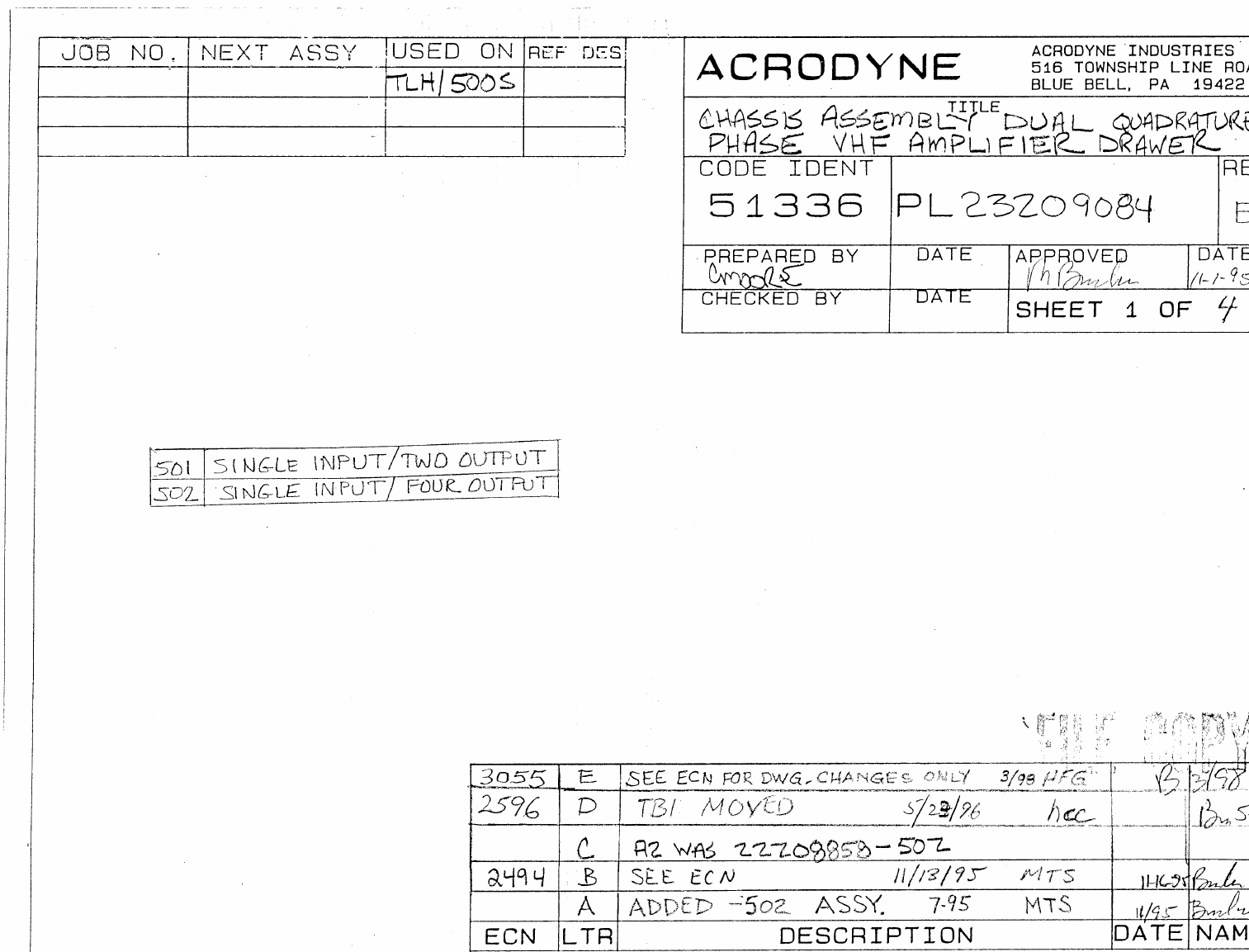
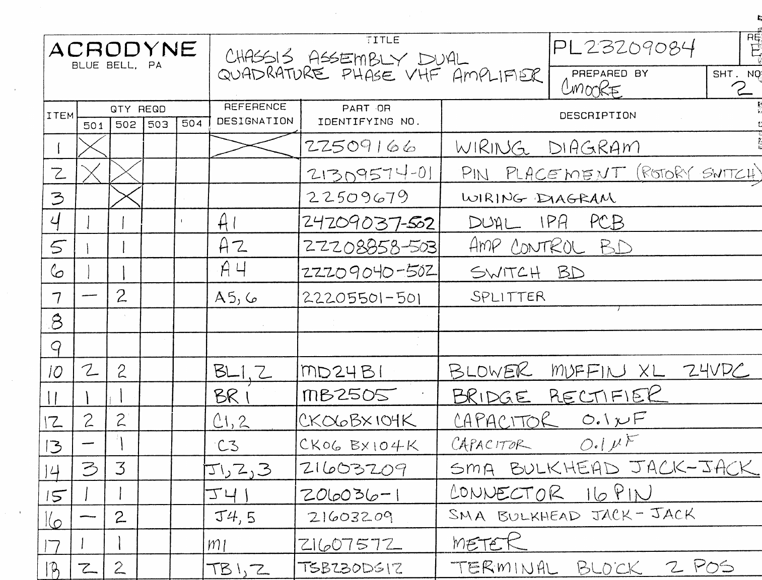
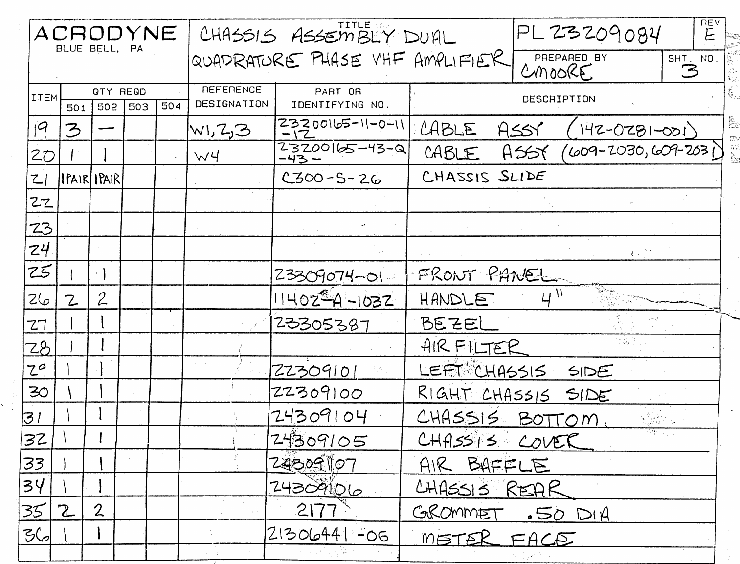
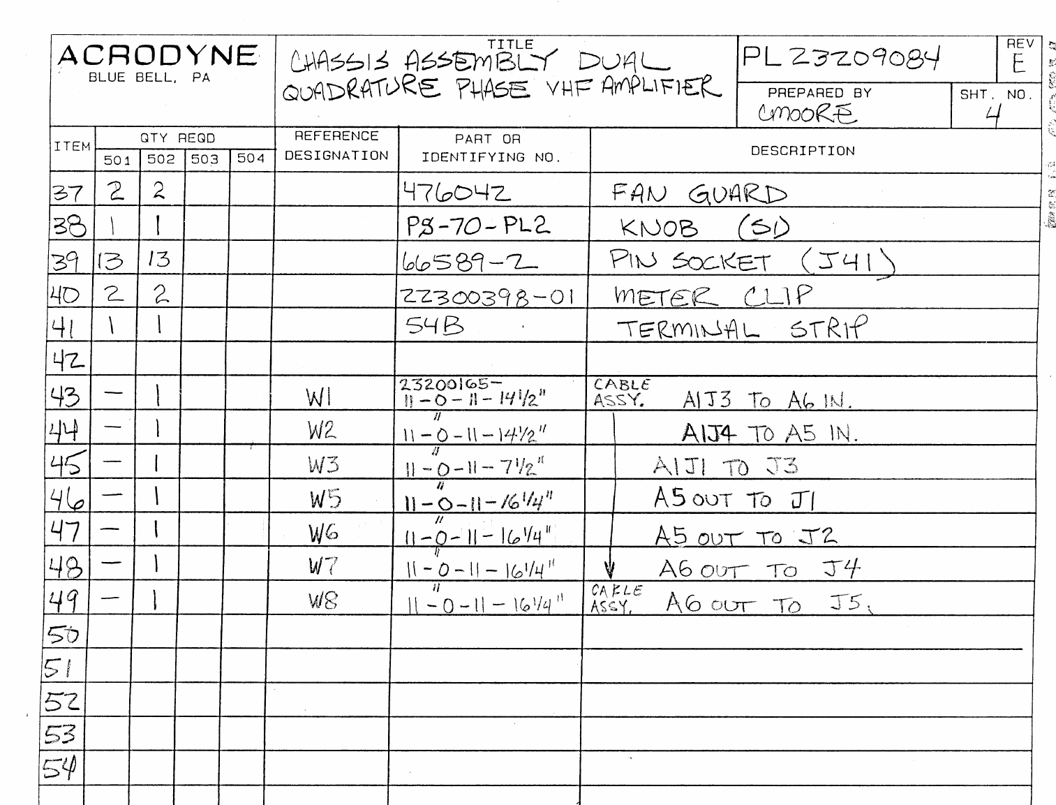
JOB NO.
NEXT ASSY.
USED ON
REF. DES.
22210658
ASSY
DESCRIPTION
-501 FOR STANDARD “ M “ FREQUENCIES
-502 FOR STANDARD “G , I , D “ FREQUENCIES
ECN LTR DESCRIPTION REVISED BY APPROVED
BY
AADDED J2, W12 & W13 CP 10/98
2766 BADDED SHEET 13 & ITEM 76 MTS 2/97 MB 2/97
2855, 2899 CADD -502, CONVERT PL TO PENDRAFT FROMAT, UPDATE PL PER ECN 2899 HFG 6/97 MB 6/97
2952 D-501 ONLY-L6/L7 TO 22T, C175 TO 8.2PF - 11/97 HCC MB 11/97
3038, 3095 EADD C176, 177, 178, W1-11 (ITEM 46, 125-132). W13 WAS 6” LG HFG 3/98
3240, 3290 FREVISED ITEM NO #66, #71, #89 PER ECC #3240, 3290 CP 10/98
3341 GPL CHANGES, SEE ECN JJC 3/17/99
ACRODYNE INDUSTRIES
516 TOWNSHIP LINE ROAD
BLUE BELL, PA. 19422
TITLE
ASSEMBLY:
IM PLUS STATIC ICPM PCB
CODE IDENT
51336 DOCUMENT NUMBER
PL23210602
REVISION
G
PREPARED BY
MMC
CHECKED BY
J. BROOKES
DATE
09/17/96
DATE
10/30/96
APPROVED BY
DATE
ACRODYNE
SHEET 1 OF 7

QUANTITY REQUIRED REFERENCE PART OR
ITEM -501 -502 -503 -504 DES. IDENTIFYING NUMBER DESCRIPTION VENDER
PL 23210602 RevG
ACRODYNE
BLUE BELL, PA
Title
ASSEMBLY:
IM PLUS STATIC ICPM PCB PREPARED BY
MMC SHEET NO.
2
1X X X 24510587 SCHEMATIC
2
3
4 5 5 C1,18,79,97,160 CK06BX104K CAPACITOR 0.1 uF , CERAMIC
5 5 5 C2,19,82,98, 161 CK05BX223K CAPACITOR 0.022 uF CERAMIC
6 5 -C3,20 83 99,162 DM10-150J CAPACITOR 15 pF , MICA
7-5C3,20,83,99, 162 DM10-240J CAPACITOR 24 pF , MICA
8 20 20 C4,5,6,
10,25,26,31,41, CK05BX103K CAPACITOR 0.01 uF, CERAMIC
987,88,91,95,
102,103, 106
10 110,165,
166,169,173
11 32 32 C7,8,9.13.22.24.
34.36,38,39 RPE121Z5U104M50 CAPACITOR 0.01 uF , RPE
12 40,59,65,69,86,9
2,93,94,101
13 107,108,109,
113,118,141,
14 147,149,156,
164,170,171,
15 172
16 20 20 C11,16,17,32,33,
57,62,63,73,96,
111,116
199D105X0035AA1 CAPACITOR 1 uF, 35v, TANT
17 73,96,139,144,1
45, 154,159,202
18 204,206,
19 17 17 C12,21,23,35,
37,58,64,68 100B102MCA50X CAPACITOR 1000pF , CHIP
20 85,100,112,117,
140,146,148
21 155,163
22 34 34 C14,15,27,28, PCC471-BCT-ND CAPACITOR 470 pF, CHIP, A CASE

QUANTITY REQUIRED REFERENCE PART OR
ITEM -501 -502 -503 -504 DES. IDENTIFYING NUMBER DESCRIPTION VENDER
PL 23210602 RevG
ACRODYNE
BLUE BELL, PA
Title
ASSEMBLY:
IM PLUS STATIC ICPM PCB PREPARED BY
MMC SHEET NO.
3
29,30,44,45,46
23 47,60,61,66,67,7
0,71,89,90
24 104,105,114,
115,127,128
25 142,143,150,
151,152,153
26 157,158,167,
168
27
28 6 -C42,43,119,120,
124,125, 100B2R7CCA500 CAPACITOR, 2.7pF CHIP
29 -2C52,132 100B2R7CCA500 CAPACITOR, 2.7pF CHIP
30 4 -C48,56,122,129 100B680KC200 CAPACITOR, 68pF CHIP
31 -5C48,49,56,122,1
29 100B151KCA300 CAPACITOR, 150pF CHIP
32 5 -C49,72,84,123,1
36 100B151KCA300 CAPACITOR, 150pF CHIP
33 4 -C50,53,130,133 100B120KC50 CAPACITOR, 12pF CHIP
34 -4C50,53,130,133 100B220KCA500X CAPACITOR, 22pF CHIP
35 2 -C121,126 100B220KCA500X CAPACITOR, 22pF CHIP
36 -2C121,126 100B390KCA500X CAPACITOR, 39pF CHIP
37 4 -C51,52,131,132 100B2R0CC500 CAPACITOR, 2.0pF CHIP
38 -2C76,124 100B2R0CC500 CAPACITOR, 2.0pF CHIP
39 -2C51,131 100B2R2CCA500 CAPACITOR, 2.2pF CHIP
40 1 -C76 100B2R2CCA500 CAPACITOR, 2.2pF CHIP
41 8 8 C54,55,80,81,
134,135 24AA021 CAPACITOR, VARIABLE
42 137,138
43 -2C72,84 100B301KCA200X CAPACITOR, 300pF CHIP
44 2 -C72,74,78 100B820KCA500X CAPACITOR, 82pF CHIP
45 2 2 C75,77 100B470KC500 CAPACITOR, 47pF CHIP
46 3 3 C176,177,178 100B100JP500X CAPACITOR, 10pF CHIP
47 -2C123,136 100B221KCA200X CAPACITOR, 220pF CHIP
48 1 1 C174 24AA020 CAPACITOR, 2-6pF TRIMMER

QUANTITY REQUIRED REFERENCE PART OR
ITEM -501 -502 -503 -504 DES. IDENTIFYING NUMBER DESCRIPTION VENDER
PL 23210602 RevG
ACRODYNE
BLUE BELL, PA
Title
ASSEMBLY:
IM PLUS STATIC ICPM PCB PREPARED BY
MMC SHEET NO.
4
49 1 -C175 100B8R2KP500X CAPACITOR, 8.2pF CHIP
50 -1C175 100B150KC500X CAPACITOR, 15pF CHIP
51 1 1 C201 21606582 CAPACITOR, 100uF, 50V, ELECTROLYTIC
52 3 3 C203,205,207 199D226X0035 CAPACITOR, 22uF, 35V, TANT
53
54 4 4 D201,202,203,
204 IN4007 DIODE
55 17 17 F1-17 2664000101 FERRITE BEAD
56
57
58 3 3 J1,3,6 RFB-1111 JACK, BNC
59 1 1 J2 31-5329 CONNECTOR, BNC, PCB, AMPHENOL
60 1 1 J7 1715721 TEMINAL BLOCK, 2 POSITION
61
62 5 -L1,2,8,9,14 1025-16 COIL, 0.68 uH
63 1 1 L3 1025-10 COIL, 0.39 uH
64 -5L1,2,8,9,14 1025-20 COIL, 1.0 uH
65 4 -L4,5,11,13 11300530-22-149-0 COIL, 14T 22ENAM T37-0
66 -2L4,5 11300530-28-179-0 COIL, 14T22ENAM T37-0
67 2 -L6,7 1300530-24-229-0 COIL, 22T 24ENAM T37-0
68 -2L6,7 11300530-26-269-0 COIL, 26T 26ENAM T37-0
69 2 -L10,12 1300530-26-269-0 COIL, 26T 26ENAM T37-0
70 -2L10,12 11300530-26-238-0 COIL, 23T 26ENAM T37-0
71 -2L11,13 11300530-28-169-0 COIL, 14T22ENAM T37-0
72 1 1 L15 11300530-30-23A-0 COIL, 23T 30ENAM T25-10
73 1 1 L16 1025-24 COIL, 1.50 uH
74 3 3 L17,19,20 1025-26 COIL, 1.80 uH
75 1 1 Ll18 1025-28 COIL, 2.20 uH
76
77 4 4 M1-4 SBL-1X MIXER, PCB MOUNT
78
79 5 5 R1,25,73,91, 127 3386P-1-102 POTENTIOMETER, 1K POT SQ
80 7 7 R9,39,60,67,
110,113,139 3339P-1-500 POTENTIOMETER, 50 POT ROUND

QUANTITY REQUIRED REFERENCE PART OR
ITEM -501 -502 -503 -504 DES. IDENTIFYING NUMBER DESCRIPTION VENDER
PL 23210602 RevG
ACRODYNE
BLUE BELL, PA
Title
ASSEMBLY:
IM PLUS STATIC ICPM PCB PREPARED BY
MMC SHEET NO.
5
81
82 12 12 R2,24,26,42,49,5
1,55,68,111 RC07GF680J RESISTOR, 68 OHM, .25 W
83 120,121,124
84 16 16 R3,27,44,47,50,5
3,54,58,59 RC07GF101J RESISTOR, 100 OHM, .25 W
85 71,72,114,115,1
22,125,126
86
87 11 11 R4,12,19,28,37,7
4,81,93,100 RC076F240J RESISTOR, 24Ω, .25W
88 128,137
89 4 4 R5,75,89,94 RC07GF391J RESISTOR, 390 OHM, .25 W
90 7 7 R6,15,30,76,95,1
02,130 RC07GF201J RESISTOR, 200 OHM, 25 W
91 15 15 R7,8,13,31,34,
41,77,78,84 RC07GF751J RESISTOR, 750 OHM, .25 W
92 96,97,103,131,1
34,141
93
94 17 17 R10,11,21,22,
35,36,52,61,62, RC07GF510J RESISTOR, 51 OHM, .25 W
95 79,80,98,99,
117,118,135
96 136
97 5 5 R14,38,82,101,1
38 RC07GF302J RESISTOR, 3K OHM, .25 W
98 1 1 R16 RC07GF112J RESISTOR, 1100 OHM, .25 W
99 10 10 R17,18,43,45,
87,88,104, RC07GF241J RESISTOR, 240 OHM, .25 W
100 105,142,143
101 3 3 R20,106,123 RC07GF221J RESISTOR, 220 OHM, .25 W
102 2 2 R23,83 RC07GF181J RESISTOR, 180 OHM, .25 W
103 2 2 R29,129 RC07GF431J RESISTOR, 430 OHM, .25 W
104 12 12 R32,33,56,57, RC07GF360J RESISTOR, 36 OHM, .25 W

QUANTITY REQUIRED REFERENCE PART OR
ITEM -501 -502 -503 -504 DES. IDENTIFYING NUMBER DESCRIPTION VENDER
PL 23210602 RevG
ACRODYNE
BLUE BELL, PA
Title
ASSEMBLY:
IM PLUS STATIC ICPM PCB PREPARED BY
MMC SHEET NO.
6
65,66,108,109
105 112,113,132,
133
106 2 2 R40,140 RC07GF161J RESISTOR, 160 OHM, .25 W
107 5 5 R46,63,69,85, 90 RC07GF121J RESISTOR, 120 OHM, .25 W
108 5 5 R48,64,70,86, 92 RC07GF750J RESISTOR, 75 OHM, .25 W
109 1 1 R107 RCO7GF620J RESISTOR, 62 OHM, .25 W
110 1 1 R119 RC07GF151J RESISTOR, 150 OHM, .25 W
111
112 5 5 S1,3,7,8,12 21606599 PCB SWITCH, SP3T
113 7 7 S2,4,5,6,9,10, 11 ASE-22 PCB SWITCH, SLIDE
114
115 5 5 T1-5 458DS-1014-P3 TRANSFERMER, DIP 6, SURFACE MOUNT
116
117 10 10 U1,2,4,5,13,14,1
6,17,25,26 TL592 IC ( NO SOCKET )
118
119 17 17 U3,6-12,15,18-
24,27 NE5205 IC ( NO SOCKET )
120
121 1 1 U201 7812 VOLTAGE REGULATOR, 12V
122 1 1 U202 7815 VOLTAGE REGULATOR, 15V
123 1 1 U203 7806 VOLTAGE REGULATOR, 6V
124
125 2 2 W1,3 23200165-5-W-5-5.25 COAX CABLE, 50 OHM
126 1 1 W2 23200165-5-W-5-8 COAX CABLE, 50 OHM
127 2 2 W4,9 23200165-5-W-5-6.25 COAX CABLE, 50 OHM
128 1 1 W5 23200165-5-W-5-9 COAX CABLE, 50 OHM
129 1 1 W6 23200165-5-W-5-7.25 COAX CABLE, 50 OHM
130 1 1 W7 23200165-5-W-5-8.5 COAX CABLE, 50 OHM
131 2 2 W8,11 23200165-5-W-5-5.50 COAX CABLE, 50 OHM
132 1 1 W10 23200165-5-W-5-10.5 COAX CABLE, 50 OHM
133 1 1 W12 23200165-41-L-5-20 CABLE ASSEMBLY
134 1 1 W13 23200165-35-L-5-10 CABLE ASSEMBLY

QUANTITY REQUIRED REFERENCE PART OR
ITEM -501 -502 -503 -504 DES. IDENTIFYING NUMBER DESCRIPTION VENDER
PL 23210602 RevG
ACRODYNE
BLUE BELL, PA
Title
ASSEMBLY:
IM PLUS STATIC ICPM PCB PREPARED BY
MMC SHEET NO.
7
135
136 6 6 PFC2-632-40 SCREW, CAPTIVE, # 6-32
137 1 1 22310662 PLATE, HEATSINK
138 1 1 22310667 BRACKET, CONNECTOR
139 10 10 SCREW, PAN HD, #4 - 40 X ¼” LG.
140 7 7 WASHER, FLAT. #4
141 10 10 WASHER, LOCK #4
142
143 1 1 TAK PAK 444 ADHESIVE
144 1 1 23410601 PC BOARD
JOB NO.
NEXT ASSY.
USED ON
REF. DES.
ASSY
DESCRIPTION
501
+24VDC INPUT
502
+15VDC INPUT
ECN LTR DESCRIPTION REVISED BY APPROVED BY
3129 - THIS ECN IN EFFECT WHEN PCB 23411633 REV - IS USED WB 5/5/98
3127 A SWITCH S4 WAS 21606599 WB 5/5/98 CSM
B PARTS LIST CORRECTIONS, AND IMPROVED PCB ARTWORK WB 6/6/98
3208 C W3’S LENGTH WAS 16 JJC 10/06/98
D ADD 502 VERSION, (DELETE R72,R73,R74,R75) REPLACE WITH BUSSWIRE. KH 10/13/98
ACRODYNE INDUSTRIES
516 TOWNSHIP LINE ROAD
BLUE BELL, PA. 19422
TITLE
PCB ASSEMBLY: AURAL PILOT CORRECTOR AND
AURAL LEVELING CIRCUIT
CODE IDENT
51336 DOCUMENT NUMBER
PL23211632-501 REVISION
D
PREPARED BY
MMC
CHECKED BY
DATE
12/97
DATE
APPROVED BY
DATE
ACRODYNE
SHEET 1 OF 5
REFERENCE PART OR
ITEM QTY DES. IDENTIFYING NUMBER DESCRIPTION
Title
PCB ASSEMBLY: AURAL PILOT
CORRECTOR & AURAL LEVELING CIRCUIT
ACRODYNE
BLUE BELL, PA
PL 23211632-501 REV D
PREPARED BY
MMC SHEET NO.
2
2
X X 22511634 SCHEMATIC, AURAL PILOT CORRECTOR
AND AURAL LEVELING CIRCUIT
1 15 B1,B2,B3,B4,B5,B6,B7,B8, 26640001014 FERRITE BEAD
B9,B10,B11,B12,B13,B14,
B15
2 2 C39,C60 SBT
3 5 C30,C33,C48,C51,C85 100B2R7CCA500 CHIP CAP. 2.7 PF
4 1 C6 100B3R3CCA500 CHIP CAP. 3.3 PF
5 2 C13,C10 100B6R8CC500X CHIP CAP. 6.8 PF
6 4 C26,C27,C44,C45 100B120KC50 CHIP CAP. 12 PF
7 2 C58,C80 DM10-150J CAP, 15 PF
8 2 C7,C5 100B330KCA500X CHIP CAP. 33 PF
9 2 C84,C86 100B470KC500 CHIP CAP. 47 PF
10 8 C11,C12,C36,C37,C38,C54, 100B680KC200 CHIP CAP. 68 PF
C55,C59
11 2 C93,C92 100B101MC500 CHIP CAP. 100 PF
12 6 C125,C132,C133, GRM42-6X7R102K050BL CHIP CAP. 0.001 UF
C134,C136,C137
13 2 C79,C57 CKO5BX223K CAP. CERAMIC .022 UF
14 39 C2,C15,C19,C24,C25,C42, GRM42-6X7R104K050BL CHIP CAP 0.1 UF
C43,C56,C62,C63,C64,C65,
C68,C69, C70,C71,C73,C77,
C78,C82,C83,C89,C94,C97,
C98,C99,C100,C103,C104,
C118,C121,C122,C123,C124,
C126,C128,C129,C131,C135
15 26 C3,C4,C16,C17,C20,C21, 21CC647 CHIP CAP.A CASE 470 PF
C28,C29,C34,C35,C46,C47,
C52,C53,C66,C67,C74,C75,
C87,C88,C95,C96,C105,
C106,C107,C108
16 18 C1,C14,C18,C22,C23,C40, 199D105X0035AA1 CAP 1 UF
C41,C61,C72,C76,C81,C101,
C102,C109,C111,C113,C115,
REFERENCE PART OR
ITEM QTY DES. IDENTIFYING NUMBER DESCRIPTION
Title
PCB ASSEMBLY: AURAL PILOT
CORRECTOR & AURAL LEVELING CIRCUIT
ACRODYNE
BLUE BELL, PA
PL 23211632-501 REV D
PREPARED BY
MMC SHEET NO.
3
3
C119
17 2 C120,C130 199D475X0035CAI CAP 4.7 UF
18 4 C110,C112,C114,C116 199D226X0035 CAP 22 UF
19 8 C8,C9,C31,C32,C49,C50, 24AA021 CAP VAR
C90,C91
20 1 C127 515D227M025BB6A CAP 220 UF
21 1 C117 TLB1H102M CAP 1000 UF
22 9 CR1,CR2,CR3,CR4,CR5,CR6, 1N4007 DIODE
CR7,CR8,CR9
23 1 LD2 35BL504 LED (RED)
24 1 LD1 35BL505 LED (GREEN)
25 1 LD3 35BL506 LED (YELLOW)
26 4 L3,L4,L5,L6 11300530-24-149-0 COIL 14T
27 2 L1,L2 11300530-26-209-0 COIL 20T
28 2 L10,L11 11300530-26-239-0 COIL 23T
29 2 L7,L9 1025-16 COIL 0.68 UH
30 2 L8,L12 1025-24 COIL 1.50 UH
31 3 J3,J4,J9 RFB-1113 BNC JACK
32 3 TP-A. SET1,TP-A. SENSE1, 65507-436 ONE PIN HEADER
TP-A. AGCT1
33 4 ML1,ML2,ML3,ML4 SCM - 2 MIXER PCB SURFACE MOUNT
34 1 Q1 2N3906 TRANSISTOR
35 5 R10,R33,R41,R60,R111 3339P-1-500 POTENTIOMETER 50
36 3 R16,R43,R81 3386P-1-102 POTENTIOMETER 1K
37 1 R65 RC07GF220J RES .25W 22
38 5 R19,R26,R49,R58,R106 RC07GF240J RES .25W 24
39 1 R71 RC07GF270J RES .25W 27
40 10 R8,R9,R28,R29,R37,R38, RC07GF360J RES .25W 36
R53,R54,R109,R110
41 1 R13 RC07GF390J RES .25W 39
42 1 R42 RC07GF430J RES .25W 43
43 4 R24,R25,R56,R57 RC07GF510J RES .25W 51
44 1 R68 RC07GF560J RES .25W 56
45 3 R4,R7,R99 RC07GF620J RES .25W 62

REFERENCE PART OR
ITEM QTY DES. IDENTIFYING NUMBER DESCRIPTION
Title
PCB ASSEMBLY: AURAL PILOT
CORRECTOR & AURAL LEVELING CIRCUIT
ACRODYNE
BLUE BELL, PA
PL 23211632-501 REV D
PREPARED BY
MMC SHEET NO.
4
4
46 1 R46 RC07GF680J RES .25W 68
47 3 R2,R36,R40 RC07GF750J RES .25W 75
48 2 R1,R48 RC07GF101J RES .25W 100
49 2 R44,R45 RC07GF151J RES .25W 150
50 2 R14,R15 RC07GF161J RES .25W 160
51 6 R3,R5,R21,R47,R51,R67 RC07GF201J RES .25W 200
52 5 R6,R70,R87,R107,R108 RC07GF221J RES .25W 220
53 7 R30,R32,R35,R61,R63,R64, RC07GF241J RES .25W 240
R66
54 2 R103,R115 RC07GF301J RES .25W 300
55 4 R20,R34,R39,R50 RC07GF361J RES .25W 360
56 1 R95 RC07GF391J RES .25W 390
57 1 R101 RC07GF681J RES .25W 680
58 6 R22,R23,R52,R55,R85,R98 RC07GF751J RES .25W 750
59 8 R11,R12,R17,R18,R31,R62, RC07GF102J RES .25W 1K
R79,R86
60 1 R105 RC07GF132J RES .25W 1.3K
61 1 R102 RC07GF152J RES .25W 1.5K
62 6 R76,R77,R84,R89,R100,R116 RC07GF202J RES .25W 2K
63 4 R27,R59,R69,R94 RC07GF302J RES .25W 3K
64 1 R97 RC07GF752J RES .25W 7.5K
65 2 R104,R88 RC07GF393J RES .25W 39K
66 1 R80 RC07GF753J RES .25W 75K
67 1 R90 RC07GF913J RES .25W 91K
68 3 R82,R92,R93 RC07GF154J RES .25W 150K
69 1 R96 RC20GF471J RES .5W 470
70 3 R78,R83,R91 RC20GF621J RES .5W 620
71 2 R112,R113 RC42GF100J RES 2W 10
72 4 R72,R73,R74,R75 RC42GF470J RES 2W 47
73 1 S3 ASE-22 PCB SLIDE SWITCH
74 2 S1,S2 21606599 PCB SWITCH SP3T
75 3 T1,T2,T3 TKS2518CT TRANSFORMER PCB
76 2 TB1 1715721 TERM. BLK 2 POS
77 1 U18 LM339 IC QUAD COMPARATOR
REFERENCE PART OR
ITEM QTY DES. IDENTIFYING NUMBER DESCRIPTION
Title
PCB ASSEMBLY: AURAL PILOT
CORRECTOR & AURAL LEVELING CIRCUIT
ACRODYNE
BLUE BELL, PA
PL 23211632-501 REV D
PREPARED BY
MMC SHEET NO.
5
5
78 1 U20 LM358 IC DUAL OP AMP 8 PIN
79 14 U1,U2,U3,U4,U5,U6,U7,U10, NE5205AN IC (NO SOCKET)
U11,U14,U15,U16,U17,U21
80 1 AF1 AF002N2-32 GaAs ATTENUATOR,SOT-143
81 4 U8,U9,U12,U13 NE592N8 IC
82 1 U19 ULN2004A IC HEX INVERTER
83 2 VR2,VR4 7806 VOLTAGE REG 6V
84 3 VR1,VR3,VR5 7812 VOLTAGE REG 12V
85 1 VR6 NJM78L06A VOLTAGE REG, TO-92
86 1 W3 23200165-5-L-41-18 RG-316 COAX CABLE 50 OHM, ASSEMBLY
87 9 PFC2-632-40 CAPTIVE SCREW INSERT
88 1 PWB 23411633 PRINTED WIRING BOARD
89 2 W1, W4 23200165-5-L-41-16 RG-316 COAX CABLE 50 OHM, ASSEMBLY
90 1 W2 23200165-5-W-5-7.125 RG-178 COAX CABLE 50 OHM, ASSEMBLY
91 1 W5 23200165-5-W-5-3.375 RG-178 COAX CABLE 50 OHM, ASSEMBLY
92 1 W6 23200165-5-W-5-6.375 RG-178 COAX CABLE 50 OHM, ASSEMBLY
93 1 -21311670-01 HEATSINK PLATE
94 1 R114 RC07GF123J RESISTOR .25W 12K
95 1 XU18 CA14TSD IC SOCKET, 14 PIN
96 7 #4 X 5/16” LG RD HD SCREW <VR1-5 & HEATSINK>
97 2 #4 FLAT WASHER < HEATSINK>
98 7 #4 LOCK WASHER <VR1-5 & HEATSINK>
99 1 #4 NUT <VR5>
100 5 175-6-240P THERMAL TRANSFER PAD WAKEFIELD
<VR1,VR2,VR3,VR4,VR5>
101 1 XU20 C8414-02 IC SOCKET, 8 PIN
102 1 XU19 CA16TSD IC SOCKET, 16 PIN
103 1 S4 21607023 PCB SWITCH SPDT
104 4 #18 GAUGE BUSS W/SLEVE, LENGTH AS
REQUIRED
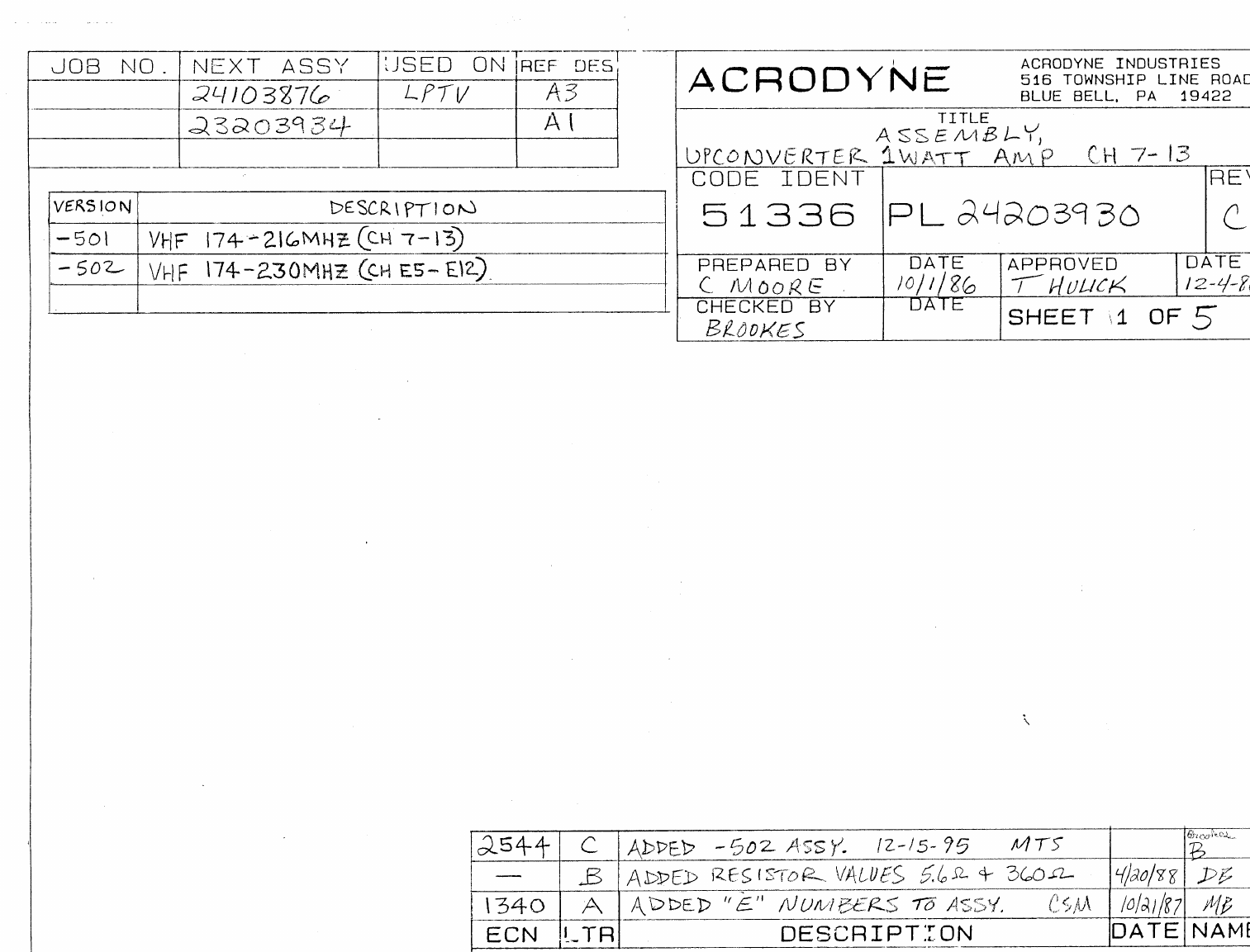
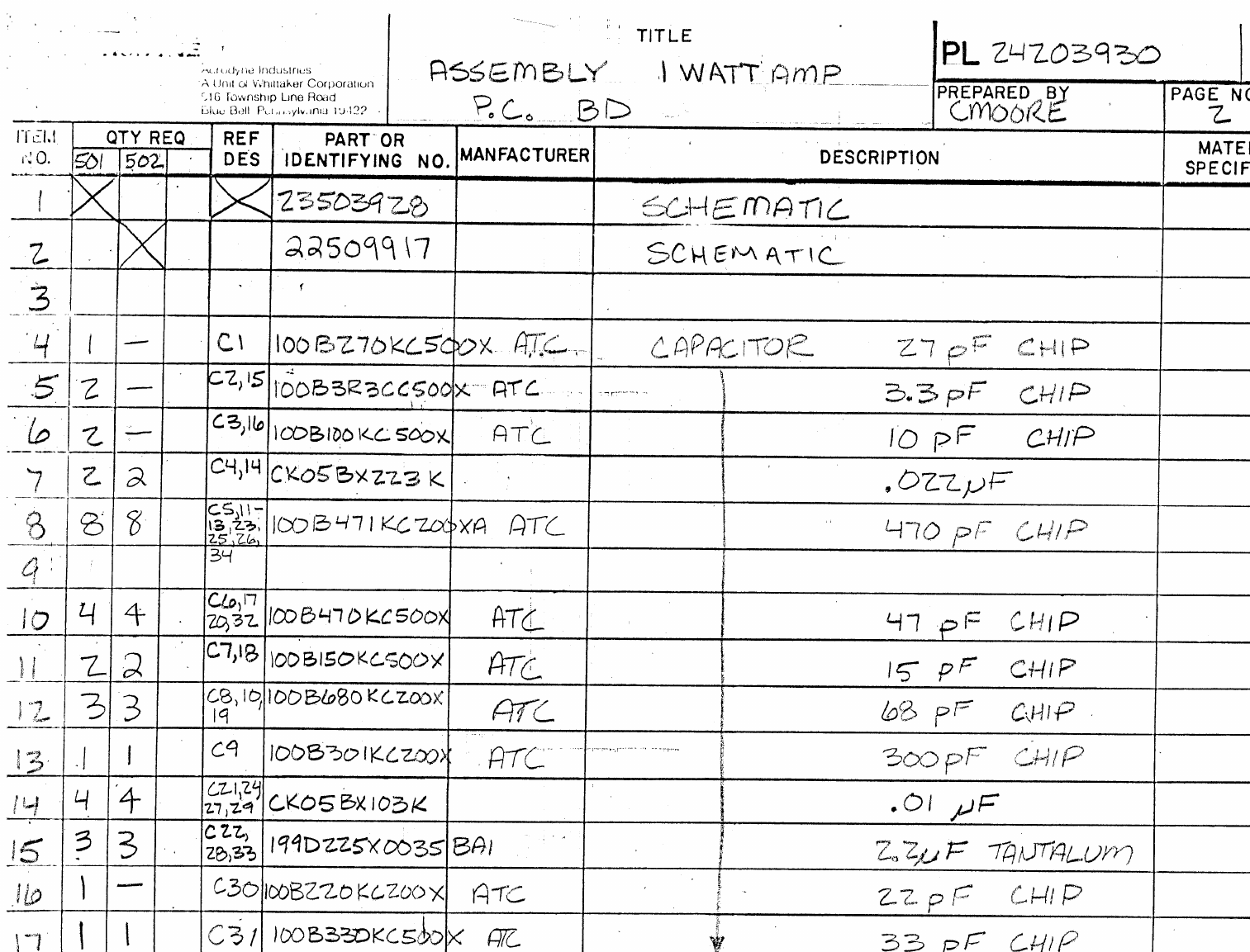
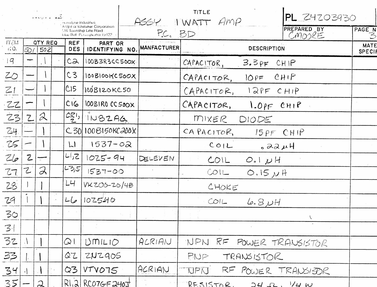
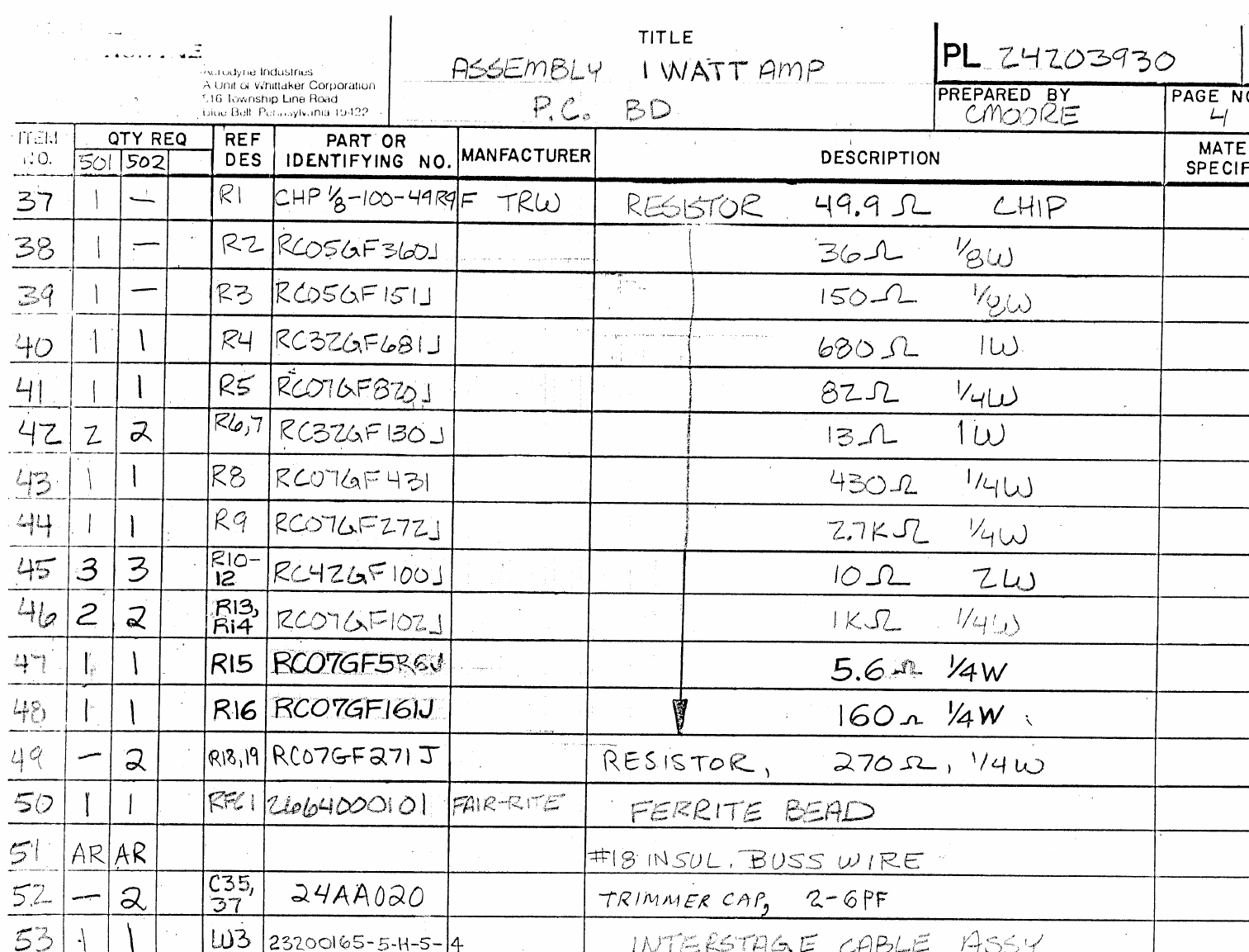
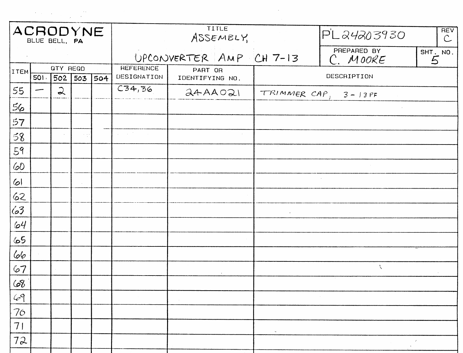
JOB NO.
NEXT ASSY.
USED ON
REF. DES.
23206106
A1
ASSY
DESCRIPTION
501 PLL STANDARD FREQ TOL SINGLE OUTPUT
502 PLL ±1000HZ FREQ TOL SINGLE OUTPUT
503 SAME AS 501 DUAL OUTPUT
504 SAME AS 502 DUAL OUTPUT
505 501 MINUS PCB
506 502 MINUS PCB
507 503 MINUS PCB
508 504 MINUS PCB
ECN LTR DESCRIPTION REVISED BY APPROVED BY
A
B
C DELETED R18 22/22/93 B
2042 D SEE ENC 2/22/93 B
2116 E SEE ECN SGM 6/16/93 B
2154 F ADDED 505,506 SGM 6/16/93 B
2574 G ITEM 23 TO ‘SBT’ HCC 5/15/96 B
2614 H ITEM 10, PN 21GC647 →PCC471BGT HCC 8/24/96 B 8/96
2614 H ITEM 10, PN 21GC647 →PCC471BGT HCC 8/24/96 B 8/96
3270 I ADDED- 507& 508 ASSY. 2/98 MTS B 3/98
ACRODYNE INDUSTRIES
516 TOWNSHIP LINE ROAD
BLUE BELL, PA. 19422
TITLE
VHF HIGHBAND L.O. PC BD
CODE IDENT
51336 DOCUMENT NUMBER
PL24206064
REVISION
J
PREPARED BY
C. MOORE
CHECKED BY
DATE
9/26/91
DATE
APPROVED BY
D. HULICK DATE
7/24/92
ACRODYNE
SHEET 1 OF 7
QUANTITY REQUIRED REFERENCE PART OR
ITEM -501 -502 -503 -504 DES. IDENTIFYING NUMBER DESCRIPTION VENDER
Title
VHF HIGHBAND L.O.
PC BD.
ACRODYNE
BLUE BELL, PA
PL 24206064 Rev J
SHEET NO.
2
PREPARED BY
C. MOORE
1X X -X23506044 SCHEMATIC CYRSTAL
2X X X 23507429 SCHEMATIC TCXO
3
4
5 4 4 4 4 AR1-4 MSA0485 AMPLIFIER (SPIDER)
6
7 1 1 1 1 C1 100B1R0CC500X CAPACITOR 1PF CHIP
8 6 6 6 6 C2-5,
11, 15 100B100KC500X CAPACITOR 10PF CHIP
9 1 1 1 1 C6 100B6R8CC500X CAPACITOR 6.8 PF CHIP
10 5 5 5 5 C7-
10,16 PCC471BCT CAPACITOR 470 PF CHIP
11 3 3 3 3 C12,17
,26 199D106X9035CAI CAPACITOR 10 uF 35V TANT
12 2 2 2 2 C13,34 24AA021 CAPACITOR VARIABLE
13 1 1 1 1 C18 100B180KC500X CAPACITOR 18 PF CHIP
14 1 1 1 1 C19 100B101KC50X CAPACITOR 100 PF CHIP
15
16 1 1 1 1 C21 199D475X0035CAI CAPACITOR 4.7 uF 35V TANT
17 2 2 2 2 C22,30 CK05BX102K CAPACITOR .001 uF
18 2 2 2 2 C23,33 CK05BX103K CAPACITOR 0.01 uF
19 -1-1C27 CK05BX102K CAPACITOR .001 uF
20 3 3 3 3 C24,25
,36 1990225X0035BAI CAPACITOR 2.2 uF TANT
21 1 -1-C28 24AA024 CAPACITOR VARIABLE
22 1 -1-C29 DM10-390J CAPACITOR 39 PF MICA
23 1 1 1 1 C38 CAPACITOR - SBT
24
25 1 1 1 1 C14 DM5-050J CAPACITOR 5PF MICA
26 1 1 1 1 C37 199D226X0035 CAPACITOR 22uF 35V
27
28 1 1 1 1 CR1 DKV6533C DIODE
29 1 1 1 1 CR2 1N4003 DIODE
30 4 4 4 4 CR5-8 1N4148A DIODE
31 1 1 1 1 CR4 35BL505 LED (GREEN)

QUANTITY REQUIRED REFERENCE PART OR
ITEM -501 -502 -503 -504 DES. IDENTIFYING NUMBER DESCRIPTION VENDER
Title
VHF HIGHBAND L.O.
PC BD.
ACRODYNE
BLUE BELL, PA
PL 24206064 Rev J
SHEET NO.
3
PREPARED BY
C. MOORE
32
33 4 4 4 4 L2-5 1025-94 COIL 0.1 uH
34 1 1 1 1 L6 1025-28 COIL 2.2 uH
35
36 1 1 1 1 Q1 MRF966 TRANSISTOR
37 1 1 1 1 Q2 2N2222A TRANSISTOR
38 1 1 1 1 Q3 2N2907A TRANSISTOR
39 -1-1Q4 2N2222A TRANSISTOR
40 - - 1 1 R1 RC07GF101J RESISTOR 100 OHM 1/4W
41 1 1 1 1 R2 RC07GF511J RESISTOR 510 OHM 1/4W
42 1 1 1 1 R3 RC07GF271J RESISTOR 270 OHM 1/4W
43 1 1 1 1 R4 RC07GF122J RESISTOR 1.2K OHM 1/4W
44 3 3 3 3 R5,7,1
7RC07GF102J RESISTOR 1K OHM 1/4W
45 1 1 1 1 R6 RC07GF104J RESISTOR 100K OHM 1/4W
46 1 1 1 1 R8 RC07GF103J RESISTOR 10K OHM 1/4W
47 1 1 1 1 R9 RC07GF682J RESISTOR 6.8K OHM 1/4W
48 1 1 1 1 R10 RC07GF304J RESISTOR 300K OHM 1/4W
49 1 1 1 1 R18 RC07GF103J RESISTOR 10K OHM 1/4W
50 1 -1-R13 RC07GF105J RESISTOR 1M OHM 1/4W
51 1 -1-R14 RC07GF272J RESISTOR 2.7K OHM 1/4W
52 2 2 2 2 R15,20 RC07GF202J RESISTOR 2K OHM 1/4W
53 1 1 1 1 R16 RC07GF241J RESISTOR 240 OHM 1/4W
54 2 2 2 2 RN1,2 4310R-101-104 100K SIP RESISTOR
55 -1-1R24 RC07GF104J RESISTOR 100K 1/4W
56 -1-1R21 RC07GF103J RESISTOR 10K 1/4W
57 -1-1R23 RC07GF102J RESISTOR 1K 1/4W
58 2 2 2 2 S1,2 76RSB08S DIP SWITCH
59 2 2 2 2 TB1 1715721 TERMINAL BLOCK 4 POS
60 1 1 1 1 R22 RC07GF393J RESISTOR 39K 1/4W
61 1 1 1 1 R19 RC07GF105J RESISTOR 1MEG OHM 1/4W
62
63 1 1 1 1 U2 PB572C I.C. NEC
64 1 1 1 1 U3 NE555 I.C.
65 6 6 6 6 U4,5,8- MC14526B I.C.

QUANTITY REQUIRED REFERENCE PART OR
ITEM -501 -502 -503 -504 DES. IDENTIFYING NUMBER DESCRIPTION VENDER
Title
VHF HIGHBAND L.O.
PC BD.
ACRODYNE
BLUE BELL, PA
PL 24206064 Rev J
SHEET NO.
4
PREPARED BY
C. MOORE
11
66 1 1 1 1 U6 CD4060B I.C. (MC14060BCP)
67 1 1 1 1 U7 MC14046B I.C.
68 1 1 1 1 VR1 LM117H VOLTAGE REQULATOR
69
70 1 -1-Y1 21606403 8000 KHz CRYSTAL
71 -1-1Y2 252Y0811 TCX0 8000KHz
72
73
74
75
76
77 1 1 1 1 24406065 PC BD
78 1 1 1 1 C8408-026 I.C. SOCKET 8 PIN (U3)
79 8 8 8 8 CA16CS2-TSD I.C. SOCKET 16 PIN
80 4 4 4 4 9706-BB-0440 STANDOFF 3/16” LG 4-40 THD
81
82
83
84

QUANTITY REQUIRED REFERENCE PART OR
ITEM -505 -506 -507 -508 DES. IDENTIFYING NUMBER DESCRIPTION VENDER
Title
VHF HIGHBAND L.O.
PC BD.
ACRODYNE
BLUE BELL, PA
PL 24206064 Rev J
SHEET NO.
5
PREPARED BY
C. MOORE
1X X -X23506044 SCHEMATIC CYRSTAL
2X X X 23507429 SCHEMATIC TCXO
3
4
5 4 4 4 4 AR1-4 MSA0485 AMPLIFIER (SPIDER)
6
7 1 1 1 1 C1 100B1R0CC500X CAPACITOR 1PF CHIP
8 6 6 6 6 C2-5,
11, 15 100B100KC500X CAPACITOR 10PF CHIP
9 1 1 1 1 C6 100B6R8CC500X CAPACITOR 6.8 PF CHIP
10 5 5 5 5 C7-
10,16 PCC471BCT CAPACITOR 470 PF CHIP
11 3 3 3 3 C12,17
,26 199D106X9035CAI CAPACITOR 10 uF 35V TANT
12 2 2 2 2 C13,34 24AA021 CAPACITOR VARIABLE
13 1 1 1 1 C18 100B180KC500X CAPACITOR 18 PF CHIP
14 1 1 1 1 C19 100B101KC50X CAPACITOR 100 PF CHIP
15
16 1 1 1 1 C21 199D475X0035CAI CAPACITOR 4.7 uF 35V TANT
17 2 2 2 2 C22,30 CK05BX102K CAPACITOR .001 uF
18 2 2 2 2 C23,33 CK05BX103K CAPACITOR 0.01 uF
19 -1-1C27 CK05BX102K CAPACITOR .001 uF
20 3 3 3 3 C24,25
,36 1990225X0035BAI CAPACITOR 2.2 uF TANT
21 1 -1-C28 24AA024 CAPACITOR VARIABLE
22 1 -1-C29 DM10-390J CAPACITOR 39 PF MICA
23 1 1 1 1 C38 DM10-361J CAPACITOR - 360 PF MICA
24
25 1 1 1 1 C14 DM5-050J CAPACITOR 5PF MICA
26 1 1 1 1 C37 199D226X0035 CAPACITOR 22UF 35V
27
28 1 1 1 1 CR1 DKV6533C DIODE
29 1 1 1 1 CR2 1N4003 DIODE
30 4 4 4 4 CR5-8 1N4148A DIODE
31 1 1 1 1 CR4 35BL505 LED (GREEN)

QUANTITY REQUIRED REFERENCE PART OR
ITEM -505 -506 -507 -508 DES. IDENTIFYING NUMBER DESCRIPTION VENDER
Title
VHF HIGHBAND L.O.
PC BD.
ACRODYNE
BLUE BELL, PA
PL 24206064 Rev J
SHEET NO.
6
PREPARED BY
C. MOORE
32
33 4 4 4 4 L2-5 1025-94 COIL 0.1 uH
34 1 1 1 1 L6 1025-28 COIL 2.2 uH
35
36 1 1 1 1 Q1 MRF966 TRANSISTOR
37 1 1 1 1 Q2 2N2222A TRANSISTOR
38 1 1 1 1 Q3 2N2907A TRANSISTOR
39 -1-1Q4 2N2222A TRANSISTOR
40 - - 1 1 R1 RC07GF101J RESISTOR 100 OHM 1/4W
41 1 1 1 1 R2 RC07GF511J RESISTOR 510 OHM 1/4W
42 1 1 1 1 R3 RC07GF271J RESISTOR 270 OHM 1/4W
43 1 1 1 1 R4 RC07GF122J RESISTOR 1.2K OHM 1/4W
44 3 3 3 3 R5,7,1
7RC07GF102J RESISTOR 1K OHM 1/4W
45 1 1 1 1 R6 RC07GF104J RESISTOR 100K OHM 1/4W
46 1 1 1 1 R8 RC07GF103J RESISTOR 10K OHM 1/4W
47 1 1 1 1 R9 RC07GF682J RESISTOR 6.8K OHM 1/4W
48 1 1 1 1 R10 RC07GF304J RESISTOR 300K OHM 1/4W
49 1 1 1 1 R18 RC07GF103J RESISTOR 10K OHM 1/4W
50 1 -1-R13 RC07GF105J RESISTOR 1M OHM 1/4W
51 1 -1-R14 RC07GF272J RESISTOR 2.7K OHM 1/4W
52 2 2 2 2 R15,20 RC07GF202J RESISTOR 2K OHM 1/4W
53 1 1 1 1 R16 RC07GF241J RESISTOR 240 OHM 1/4W
54 2 2 2 2 RN1,2 4310R-101-104 100K SIP RESISTOR
55 -1-1R24 RC07GF104J RESISTOR 100K 1/4W
56 -1-1R21 RC07GF103J RESISTOR 10K 1/4W
57 -1-1R23 RC07GF102J RESISTOR 1K 1/4W
58 2 2 2 2 S1,2 76RSB08S DIP SWITCH
59 TB1 1715721 TERMINAL BLOCK 4 POS
60 1 1 1 1 R22 RC07GF393J RESISTOR 39K 1/4W
61 1 1 1 1 R19 RC07GF105J RESISTOR 1MEG OHM 1/4W
62
63 1 1 1 1 U2 PB572C I.C. NEC
64 1 1 1 1 U3 NE555 I.C.
65 6 6 6 6 U4,5,8- MC14526B I.C.

QUANTITY REQUIRED REFERENCE PART OR
ITEM -505 -506 -507 -508 DES. IDENTIFYING NUMBER DESCRIPTION VENDER
Title
VHF HIGHBAND L.O.
PC BD.
ACRODYNE
BLUE BELL, PA
PL 24206064 Rev J
SHEET NO.
7
PREPARED BY
C. MOORE
11
66 1 1 1 1 U6 CD4060B I.C. (MC14060BCP)
67 1 1 1 1 U7 MC14046B I.C.
68 1 1 1 1 VR1 LM117H VOLTAGE REQULATOR
69
70 1 -1-Y1 21606403 8000 KHZ CRYSTAL
71 -1-1Y2 252Y0811 TCX0 8000KHz
72
73
74
75
76
77 - - - - 24406065 PC BD
78 1 1 1 1 C8408-026 I.C. SOCKET 8 PIN (U3)
79 8 8 8 8 CA16CS2-TSD I.C. SOCKET 16 PIN
80 9706-BB-0440 STANDOFF 3/16” LG 4-40 THD
81
82
83
84
85
JOB NO.
NEXT ASSY.
USED ON
REF. DES.
ASSY
DESCRIPTION
ECN LTR DESCRIPTION REVISED BY APPROVED BY
2437
2436 ASEE ECN 2/8/95 MTS 3/95 B
2499 BADDED C222. C322 11/13/95 B 11/95
CCHANGED ITEM 81 FROM 23309014 M.C. 12/2/95 B
DADDED ITEM 44 12/13/95 B
2538 ESEE ECN MC 1/15/96 B 1/96
2677 FITEM 66 ADJUSTED - 11/96 HCC 11/96 B
2898 GITEM 49 P.N. CHANGED - 9/97 HCC 10/97 M.B.
3011
3012 HSEE ECN PAGE 8 ADDED HERE - 1/98 HCC 02/98 M.B.
3060
3094 ISEE ECN ADD ITEM 110. 109 WAS 22311681 - 03 HFG 3/31/98 4/8/98 M.B.
3115
3116 JSEE ECN ADD ITEM 119
DWM 4/24/98 MV
3160
3225 KCHANGED QUANTITIES OF #’ S 111,12
JJC 09/09/98 10/16 MV
3292 L SEE ECN 12/17/98
ACRODYNE INDUSTRIES
516 TOWNSHIP LINE ROAD
BLUE BELL, PA. 19422
TITLE
ASSEMBLY:
VHF HIGH BAND LEFT 300 W PA
CODE IDENT
51336 DOCUMENT NUMBER
PL24209000
REVISION
L
PREPARED BY
HGF
CHECKED BY
DATE
11/15/94
DATE
APPROVED BY DATE
ACRODYNE
SHEET 1 OF 6

QUANTITY REQUIRED REFERENCE PART OR
ITEM -501-502 -503 -504 DES. IDENTIFYING NUMBER DESCRIPTION VENDER
PL24209000 Rev L
ACRODYNE
BLUE BELL, PA
Title
VHF HIGH BAND
LEFT 300 W PAPREPARED BY
HFG SHEET NO.
2
1X X 24509085 SCHEMATIC
2X21709162 CAP PLACEMENT
3X21709162 CAP PLACEMENT
4
5 4 B101,102,201
,301 2664000101 FERRITE BEAD
6 4 C1,2,3,4 1280-060 CAPACITOR, FEEDTHRU, 1000pF, 25A/2500V
7 2 C5,6 54-713-001-102P CAPACITOR, FEEDTHRU, 1000pF, 5A
8 2 C7,8 100B6R8CCA500X CAPACITOR, CHIP 6.8pF
9 3 C101,201,301 24AA021 CAPACITOR, VARIABLE
10 18 C102,107,114,
117,120,123,202
,203,206,210,
213,217,302,
303,306,310,313
, 317
100B102MCA50X CAPACITOR, CHIP, 1000pF
11
12
13 20 C104,105,115,
118,121,124,204
,205,207,211,
214,218,220,304
,305,307,311,
314,318,320
RPE121Z5U104M CAPACITOR, 0.1uF
14
15
16
17 2 C108,112 TLB1A102 CAPACITOR, 1000uF, 10V, ELECT
18 4 C109,113,125,
126 25VBSL-470 CAPACITOR, 470uF, 35V
19 4 C209,216,309,
316 TLB1H102M CAPACITOR, 1000uF, 50V ELECT
20 2 C110,111 TLB1J470M CAPACITOR, 47uF, 50V, ELECT
21 12 C103,106,116,
122,208,212,215 199D226X0035 CAPACITOR, 22uF, 35V, TANT

QUANTITY REQUIRED REFERENCE PART OR
ITEM -501-502 -503 -504 DES. IDENTIFYING NUMBER DESCRIPTION VENDER
PL24209000 Rev L
ACRODYNE
BLUE BELL, PA
Title
VHF HIGH BAND
LEFT 300 W PAPREPARED BY
HFG SHEET NO.
3
,219,308,312,
315,319
22
23 2 C321,221 199D225X0035BAI CAPACITOR, 2.2uF, 35V, TANT
24 2 C222,322 10EN-IT CAPACITOR, 1000uF, 10V
25 2 CR101,102 1N4002 DIODE, 100V, 1A
26 3 F1,2,3 AGC15 FUSE, 15A
27 2 J1,2 TSM-110-01-T-DV 20 PIN HEADER, SURFACE MOUNT
28 6 L101,102,201,
202,301,302 11300531-181-5R05 COIL
29 1 L103 1025-04 COIL, 0.22uH
30 3 Q1,2,3 SD1485 TRANSISTOR, RF
31 4 Q201,202,301,
302 BD135 TRANSISTOR
32 2 Q101,102 MJ371 TRANSISTOR
33
34 6 R9-13,20 3339P-1-501 POTENTIOMETER, 500 POT
35 2 R110,115 3329P-1-101 POTENTIOMETER, 100 POT
36 2 R210,310 3339P-1-502 POTENTIOMETER, 5K POT
37 1 R1 31-1007 RESISTOR, FLANGE, 100 OHM, 40 W
38 1 R2 31-1003-100 RESISTOR FLANGE, 100 OHM, 250 W
39 6 R3-8 RC07GF101J RESISTOR, 100 OHM, .25W
40 12 R101,102,103,
104,201,202,203
,204,301,302,
303,304
RC07GF2R7J RESISTOR, 2.7 OHM, .25 W
41
42 2 R105,106 RC07GF150J RESISTOR, 15 OHM .25 W
43 2 R107,112 RC20GF270J RESISTOR, 27 OHMS, .5 W
44 2 R108,113 RH25-.2 RESISTOR, 0.2 OHM, 25 W
45 2 R111,116 RC20GF272J RESISTOR, 2.7K OHM, .5 W
46 3 R117,118,119 RC20GF510J RESISTOR, 51 OHM .5W
47 2 R205,305 RC07GF240J RESISTOR, 24 OHM, .25 W
48 2 R206,306 RC07GF470J RESISTOR, 47 OHM, .25 W
49 2 R207,307 RC32GF132 RESISTOR, 1300 OHM, 1 W

QUANTITY REQUIRED REFERENCE PART OR
ITEM -501-502 -503 -504 DES. IDENTIFYING NUMBER DESCRIPTION VENDER
PL24209000 Rev L
ACRODYNE
BLUE BELL, PA
Title
VHF HIGH BAND
LEFT 300 W PAPREPARED BY
HFG SHEET NO.
4
50 4 R208,209,308,
309 RC07GF6R2J RESISTOR, 6.2 OHM, .25 W
51 3 R120,121,122 RC20GF821J RESISTOR, 820 OHM, .5 W
52 3 R123,124,125 RC20GF430J 43 OHM, .5 W
53 3 R126,127,128 RC20GF511J RESISTOR, 510 OHM, .5 W
54 3 R129,130,131 RC020GF620J RESISTOR, 62 OHM, .5 W
55 1 R132 RC20GF201J RESISTOR, 200 OHM, .5 W
56 2 R133,134 SBT RESISTOR, SBT
57 4 R211,212,311,
312 RC07GF130J RESISTOR, 13 OHM, .25 W
58
59 6 R14-19 MWS ALLOY 650 #18 MWS ALLOY 650 NiCr, 2.38 IN. LONG
60 1 TEFLON SLEEVING, 1.125 IN. LONG
61 1 TB1 8-140-3/4W TERMINAL BLOCK, 8 POSTION. SCREW DOWN
62 1 TB2 4-140-3/4W TERMINAL BLOCK, 4 POSTION, SCREW DOWN
63 1 TS1 21608653 TEMPERATURE SENSOR
64
65 1 W1 23200165-5-0-48-4 CABLE ASSEMBLY
66 1 W2 22300165-5-0-57-6 CABLE ASSEMBLY
67 1 W3 1168A COAX CABLE, 50 OHM, 10 IN. LONG
68 3 W101,201,301 RG-188 COAX CABLE, 50 OHM, 10.5 IN. LONG
69 3 W102,202,302 RG-316 COAX CABLE, 25 OHM 9-5/8 IN. LONG
70 6 TEFLON SLEEVING, 1.125 IN. LONG
71 1 TEFLON SLEEVING, 5 IN. LONG
72 6 NYLON TIE WRAPS
73 24409007 PRINTED CIRCUIT BOARD
74 1 24309018 HEATSINK
75 1 22309060 TOP WALL
76 1 22309062 FRONT WALL
77 1 22309063 BOTTOM WALL
78 1 22309061 SEPERATION WALL
79 1 22309064 REAR WALL
80 1 23309059-01 COVER
81 1 23309014 HEAT SPREADER PLATE

QUANTITY REQUIRED REFERENCE PART OR
ITEM -501-502 -503 -504 DES. IDENTIFYING NUMBER DESCRIPTION VENDER
PL24209000 Rev L
ACRODYNE
BLUE BELL, PA
Title
VHF HIGH BAND
LEFT 300 W PAPREPARED BY
HFG SHEET NO.
5
82 1 0097-0551-02 FINGER STOCK, 55” LONG
83 3 3823-1 FUSE HOLDER
84 1 23306099 TOP BAR
85 1 22305327 BOTTOM BAR
86 4 770-1871-20 MICA WAFER ( Q101,102,201, & 301 )
87 A/R THERMAL GREASE
88 3 21309038-01 TRANSISTOR CLAMP
89 3 21309038-02 TRANSISTOR CLAMP PLATE
90
91 17 #4-40 x ¼” LG PAN HD. SCREW
92 45 #4-40 x 3/8” LG. PAN HD. SCREW
93 17 #4-40 x ½” LG. PAN HD. SCREW
94 4 #4-40 x 5/8” LG. PAN HD. SCREW
95 28 #4-40 x 1-1/4” LG. FLAT HD. SCREW
96 91 #4 FLAT WASHER
97 109 #4 LOCK WASHER
98 24 #6-32 x 3/8” LG. SOCKET HD. CAP SCREW
99 24 #6 FLAT WASHER
100 24 #6 LOCK WASHER
101 4 #8-32 x ½” LG. PAN HD. SCREW
102 6 #8-32 x 5/8” LG. PAN HD. SCREW
103 10 #8 FLAT WASHER
104 10 #8 LOCK WASHER
105
106 3 #6-32 x ¼” LG. SOCKET SET SCREW
107 6 #4-40 x ¾” LG. SOCKET HD. CAP SCREW
108
109 1 22311681-04 DETAIL, VHF AMP COAX
110 1 22311681-05 DETAIL, VHF AMP COAX
111 4 21311677 ASSY, VHF AMP SCREEN CLAMP
112 4 21311678 ASSY, VHF AMP SCREENS
113
114 2 #4-40 x ½” LG. CAP HEAD SCREW
115 8 #4-40 x 3/16” LG. PAN HD. SCREW

QUANTITY REQUIRED REFERENCE PART OR
ITEM -501-502 -503 -504 DES. IDENTIFYING NUMBER DESCRIPTION VENDER
PL24209000 Rev L
ACRODYNE
BLUE BELL, PA
Title
VHF HIGH BAND
LEFT 300 W PAPREPARED BY
HFG SHEET NO.
6
116
117 1 W302 22311681-01 DETAIL, VHF AMP COAX
118 1 W202 22311681-02 DETAIL, VHF AMP COAX
119 6 B52200F006 COMPRESSION WASHER
120
121
122
123
124
125
126
127
128
JOB NO.
NEXT ASSY.
USED ON
REF. DES.
ASSY
DESCRIPTION
ECN LTR DESCRIPTION REVISED BY APPROVED BY
2437
2436 ASEE ECN 2/8/95 MTS 3/95 B
2499 BADDED C222. C322 11/13/95 B 11/95
CCHANGED ITEM 81 FROM 23309014 M.C. 12/2/95 B
DADDED ITEM 44 12/13/95 B
2538 ESEE ECN MC 1/15/96 B 1/96
2674 FITEM 80 FIXED - HCC 11/96 B
2894 GITEM 49 P.N. CHANGED - 9/97 HCC 10/97 M.B.
3011
3012 HSEE ECN PAGE 8 ADDED HERE - 1/98 HCC 02/98 M.B.
3060
3094 ISEE ECN ADD ITEM 110. 109 WAS 22311681 - 03 HFG 3/31/98 4/8/98 M.B.
3117 JSEE ECN ADD ITEM 119 DWM 4/25/98 9/09/98 MV
3160 KCHANGED QUANTITY OF #’ S 111,12 JJC 09/09/98
ACRODYNE INDUSTRIES
516 TOWNSHIP LINE ROAD
BLUE BELL, PA. 19422
TITLE
ASSEMBLY:
VHF HIGH BAND RIGHT 300 W PA
CODE IDENT
51336 DOCUMENT NUMBER
PL24209010
REVISION
K
PREPARED BY
HGF
CHECKED BY
DATE
11/15/94
DATE
APPROVED BY DATE
ACRODYNE
SHEET 1 OF 6

QUANTITY REQUIRED REFERENCE PART OR
ITEM -501-502 -503 -504 DES. IDENTIFYING NUMBER DESCRIPTION VENDER
PL24209010 Rev K
ACRODYNE
BLUE BELL, PA
Title
VHF HIGH BAND
RIGHT 300 W PAPREPARED BY
HFG SHEET NO.
2
1X X 24509085 SCHEMATIC
2X21709162 CAP PLACEMENT
3X21709162 CAP PLACEMENT
4
5 4 B101,102,201
,301 2664000101 FERRITE BEAD
6 4 C1,2,3,4 1280-060 CAPACITOR, FEEDTHRU, 1000pF, 25A/2500V
7 2 C5,6 54-713-001-102P CAPACITOR, FEEDTHRU, 1000pF, 5A
8 2 C7,8 100B6R8CCA500X CAPACITOR, CHIP 6.8pF
9 3 C101,201,301 24AA021 CAPACITOR, VARIABLE
10 18 C102,107,114,
117,120,123,202
,203,206,210,
213,217,302,
303,306,310,313
, 317
100B102MCA50X CAPACITOR, CHIP, 1000pF
11
12
13 20 C104,105,115,
118,121,124,204
,205,207,211,
214,218,220,304
,305,307,311,
314,318,320
RPE121Z5U104M CAPACITOR, 0.1uF
14
15
16
17 2 C108,112 TLB1A102 CAPACITOR, 1000uF, 10V, ELECT
18 4 C109,113,125,
126 25VBSL-470 CAPACITOR, 470uF, 35V
19 4 C209,216,309,
316 TLB1H102M CAPACITOR, 1000uF, 50V ELECT
20 2 C110,111 TLB1J470M CAPACITOR, 47uF, 50V, ELECT
21 12 C103,106,116,
122,208,212,215 199D226X0035 CAPACITOR, 22uF, 35V, TANT

QUANTITY REQUIRED REFERENCE PART OR
ITEM -501-502 -503 -504 DES. IDENTIFYING NUMBER DESCRIPTION VENDER
PL24209010 Rev K
ACRODYNE
BLUE BELL, PA
Title
VHF HIGH BAND
RIGHT 300 W PAPREPARED BY
HFG SHEET NO.
3
,219,308,312,
315,319
22
23 2 C321,221 199D225X0035BAI CAPACITOR, 2.2uF, 35V, TANT
24 2 C222,322 10EN-IT CAPACITOR, 1000uF, 10V
25 2 CR101,102 1N4002 DIODE, 100V, 1A
26 3 F1,2,3 AGC15 FUSE, 15A
27 2 J1,2 TSM-110-01-T-DV 20 PIN HEADER, SURFACE MOUNT
28 6 L101,102,201,
202,301,302 11300531-181-5R05 COIL
29 1 L103 1025-04 COIL, 0.22uH
30 3 Q1,2,3 SD1485 TRANSISTOR, RF
31 4 Q201,202,301,
302 BD135 TRANSISTOR
32 2 Q101,102 MJ371 TRANSISTOR
33
34 6 R9-13,20 3339P-1-501 POTENTIOMETER, 500 POT
35 2 R110,115 3329P-1-101 POTENTIOMETER, 100 POT
36 2 R210,310 3339P-1-502 POTENTIOMETER, 5K POT
37 1 R1 31-1007 RESISTOR, FLANGE, 100 OHM, 40 W
38 1 R2 31-1003-100 RESISTOR FLANGE, 100 OHM, 250 W
39 6 R3-8 RC07GF101J RESISTOR, 100 OHM, .25W
40 12 R101,102,103,
104,201,202,203
,204,301,302,
303,304
RC07GF2R7J RESISTOR, 2.7 OHM, .25 W
41
42 2 R105,106 RC07GF150J RESISTOR, 15 OHM .25 W
43 2 R107,112 RC20GF270J RESISTOR, 27 OHMS, .5 W
44 2 R108,113 RH25-.2 RESISTOR, 0.2 OHM, 25 W
45 2 R111,116 RC20GF272J RESISTOR, 2.7K OHM, .5 W
46 3 R117,118,119 RC20GF510J RESISTOR, 51 OHM .5W
47 2 R205,305 RC07GF240J RESISTOR, 24 OHM, .25 W
48 2 R206,306 RC07GF470J RESISTOR, 47 OHM, .25 W
49 2 R207,307 RC32GF132 RESISTOR, 1300 OHM, 1 W

QUANTITY REQUIRED REFERENCE PART OR
ITEM -501-502 -503 -504 DES. IDENTIFYING NUMBER DESCRIPTION VENDER
PL24209010 Rev K
ACRODYNE
BLUE BELL, PA
Title
VHF HIGH BAND
RIGHT 300 W PAPREPARED BY
HFG SHEET NO.
4
50 4 R208,209,308,
309 RC07GF6R2J RESISTOR, 6.2 OHM, .25 W
51 3 R120,121,122 RC20GF821J RESISTOR, 820 OHM, .5 W
52 3 R123,124,125 RC20GF430J 43 OHM, .5 W
53 3 R126,127,128 RC20GF511J RESISTOR, 510 OHM, .5 W
54 3 R129,130,131 RC020GF620J RESISTOR, 62 OHM, .5 W
55 1 R132 RC20GF201J RESISTOR, 200 OHM, .5 W
56 2 R133,134 SBT RESISTOR, SBT
57 4 R211,212,311,
312 RC07GF130J RESISTOR, 13 OHM, .25 W
58
59 6 R14-19 MWS ALLOY 650 #18 MWS ALLOY 650 NiCr, 2.38 IN. LONG
60 1 TEFLON SLEEVING, 1.125 IN. LONG
61 1 TB1 8-140-3/4W TERMINAL BLOCK, 8 POSTION. SCREW DOWN
62 1 TB2 4-140-3/4W TERMINAL BLOCK, 4 POSTION, SCREW DOWN
63 1 TS1 21608653 TEMPERATURE SENSOR
64
65 1 W1 23200165-5-0-48-3 CABLE ASSEMBLY
66 1 W2 22300165-5-0-57-6 CABLE ASSEMBLY
67 1 W3 1168A COAX CABLE, 50 OHM, 7.5 IN. LONG
68 3 W101,201,301 RG-188 COAX CABLE, 50 OHM, 10.5 IN. LONG
69 3 W102,202,302 RG-316 COAX CABLE, 25 OHM 9-5/8 IN. LONG
70 6 TEFLON SLEEVING, 1.125 IN. LONG
71 1 TEFLON SLEEVING, 5 IN. LONG
72 6 NYLON TIE WRAPS
73 24409009 PRINTED CIRCUIT BOARD
74 1 24309057 HEATSINK
75 1 22309060 TOP WALL
76 1 22309062 FRONT WALL
77 1 22309063 BOTTOM WALL
78 1 22309061 SEPERATION WALL
79 1 22309064 REAR WALL
80 1 23309059-01 COVER
81 1 23309056 HEAT SPREADER PLATE

QUANTITY REQUIRED REFERENCE PART OR
ITEM -501-502 -503 -504 DES. IDENTIFYING NUMBER DESCRIPTION VENDER
PL24209010 Rev K
ACRODYNE
BLUE BELL, PA
Title
VHF HIGH BAND
RIGHT 300 W PAPREPARED BY
HFG SHEET NO.
5
82 1 0097-0551-02 FINGER STOCK, 55” LONG
83 3 3823-1 FUSE HOLDER
84 1 23306099 TOP BAR
85 1 22305327 BOTTOM BAR
86 4 770-1871-20 MICA WAFER
87 A/R THERMAL GREASE
88 3 21309038-01 TRANSISTOR CLAMP
89 3 21309038-02 TRANSISTOR CLAMP PLATE
90 6 #8 GROUND LUG
91 17 #4-40 x ¼” LG PAN HD. SCREW
92 45 #4-40 x 3/8” LG. PAN HD. SCREW
93 17 #4-40 x ½” LG. PAN HD. SCREW
94 4 #4-40 x 5/8” LG. PAN HD. SCREW
95 28 #4-40 x 1-1/4” LG. FLAT HD. SCREW
96 91 #4 FLAT WASHER
97 109 #4 LOCK WASHER
98 24 #6-32 x 3/8” LG. SOCKET HD. CAP SCREW
99 24 #6 FLAT WASHER
100 24 #6 LOCK WASHER
101 4 #8-32 x ½” LG. PAN HD. SCREW
102 6 #8-32 x 5/8” LG. PAN HD. SCREW
103 10 #8 FLAT WASHER
104 10 #8 LOCK WASHER
105
106 3 #6-32 x ¼” LG. SOCKET SET SCREW
107 6 #4-40 x ¾” LG. SOCKET HD. CAP SCREW
108
109 1 22311681-04 DETAIL, VHF AMP COAX
110 1 22311681-06 DETAIL, VHF AMP COAX
111 4 21311677 ASSY, VHF AMP SCREEN CLAMP
112 4 21311678 ASSY, VHF AMP SCREENS
113
114 2 #4-40 x ½” LG. CAP HEAD SCREW
115 8 #4-40 x 3/16” LG. PAN HD. SCREW

QUANTITY REQUIRED REFERENCE PART OR
ITEM -501-502 -503 -504 DES. IDENTIFYING NUMBER DESCRIPTION VENDER
PL24209010 Rev K
ACRODYNE
BLUE BELL, PA
Title
VHF HIGH BAND
RIGHT 300 W PAPREPARED BY
HFG SHEET NO.
6
116
117 1 W202 22311681-01 DETAIL, VHF AMP COAX
118 1 W302 22311681-02 DETAIL, VHF AMP COAX
119 6 B52200F006 COMPRESSION WASHER
120
121
122
123
124
125
126
127
128
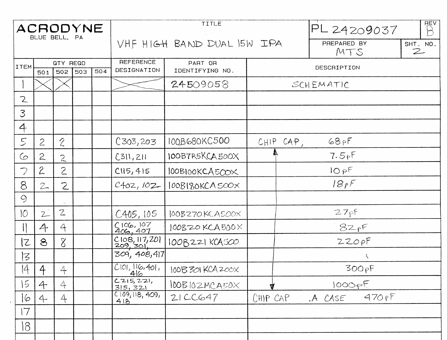
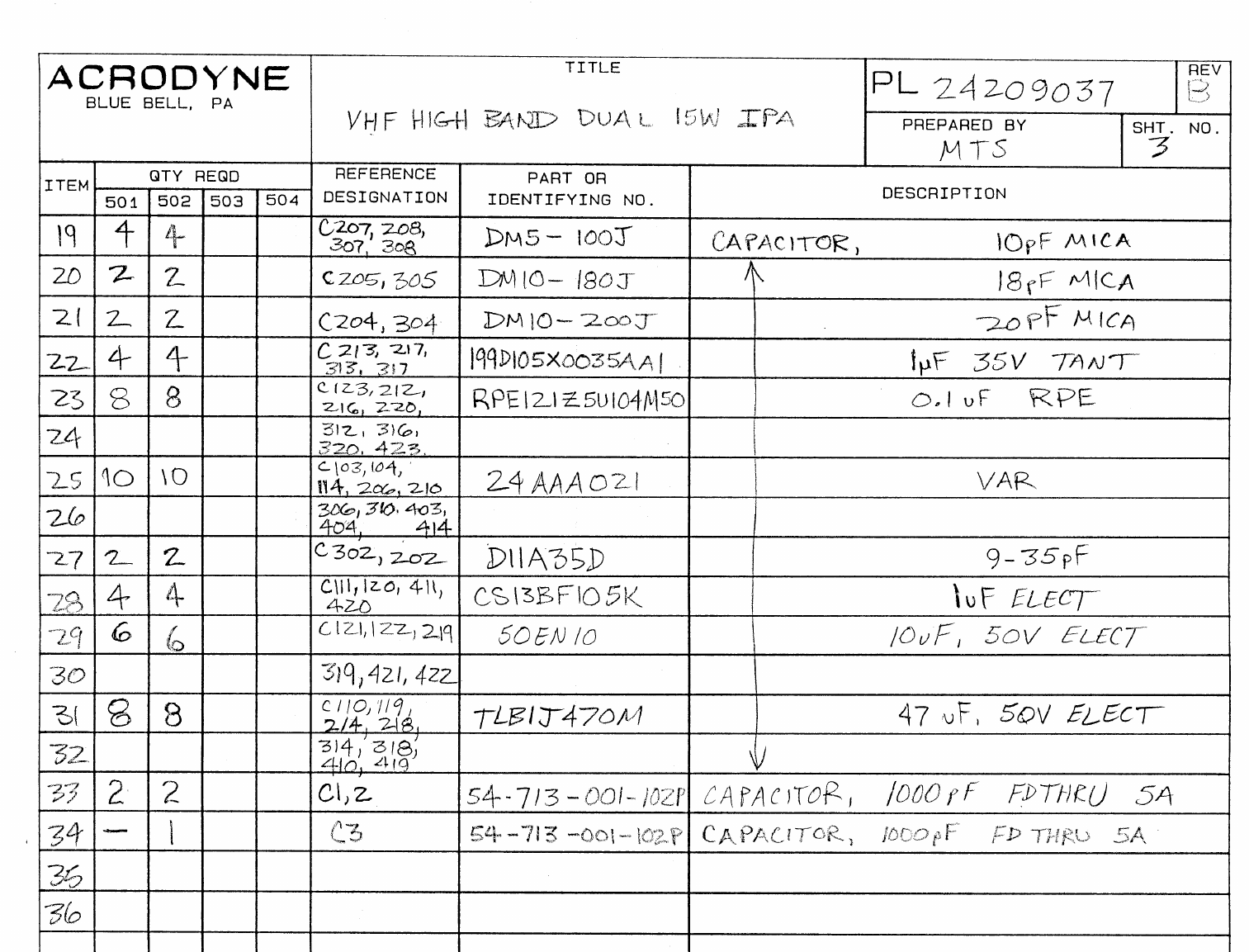
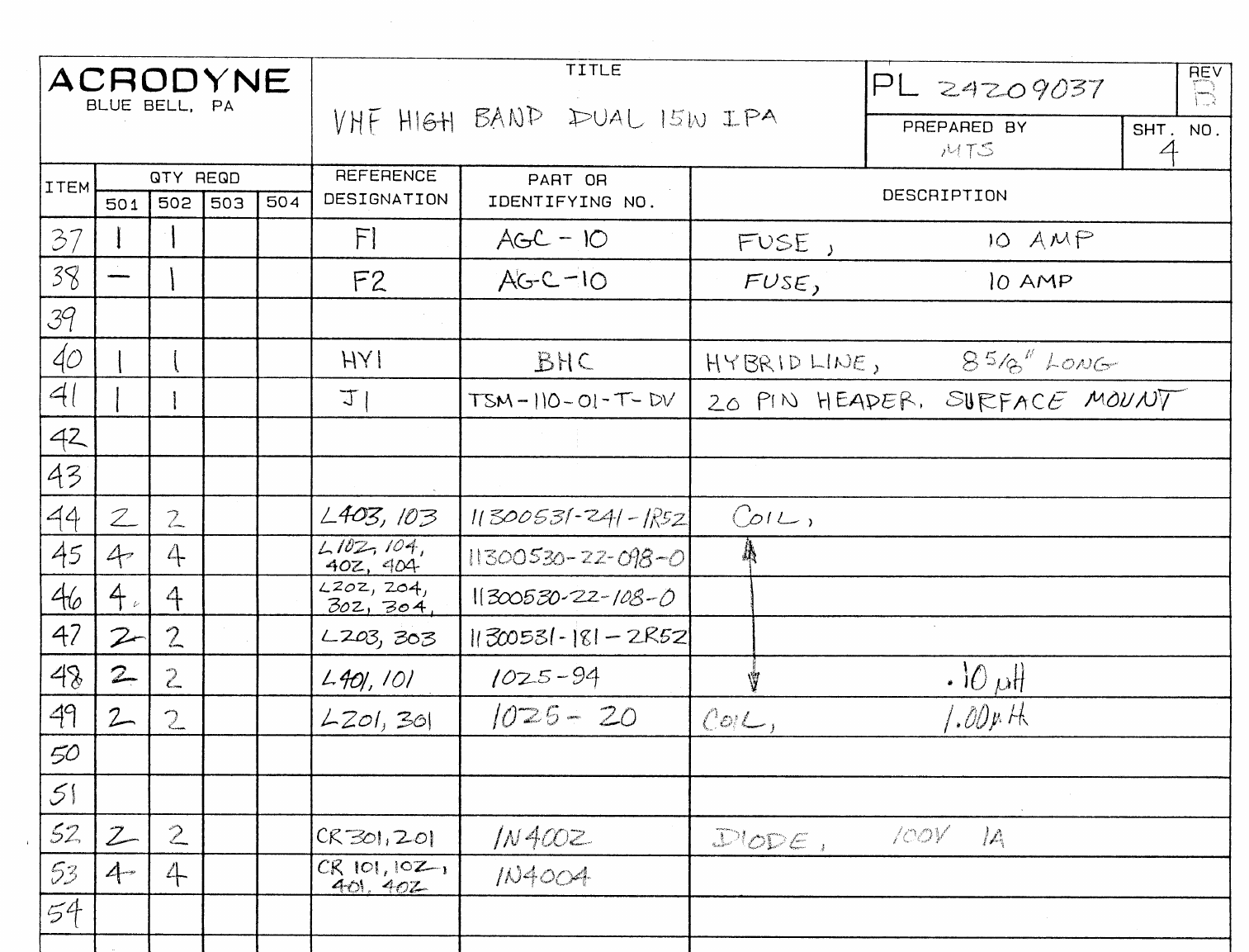
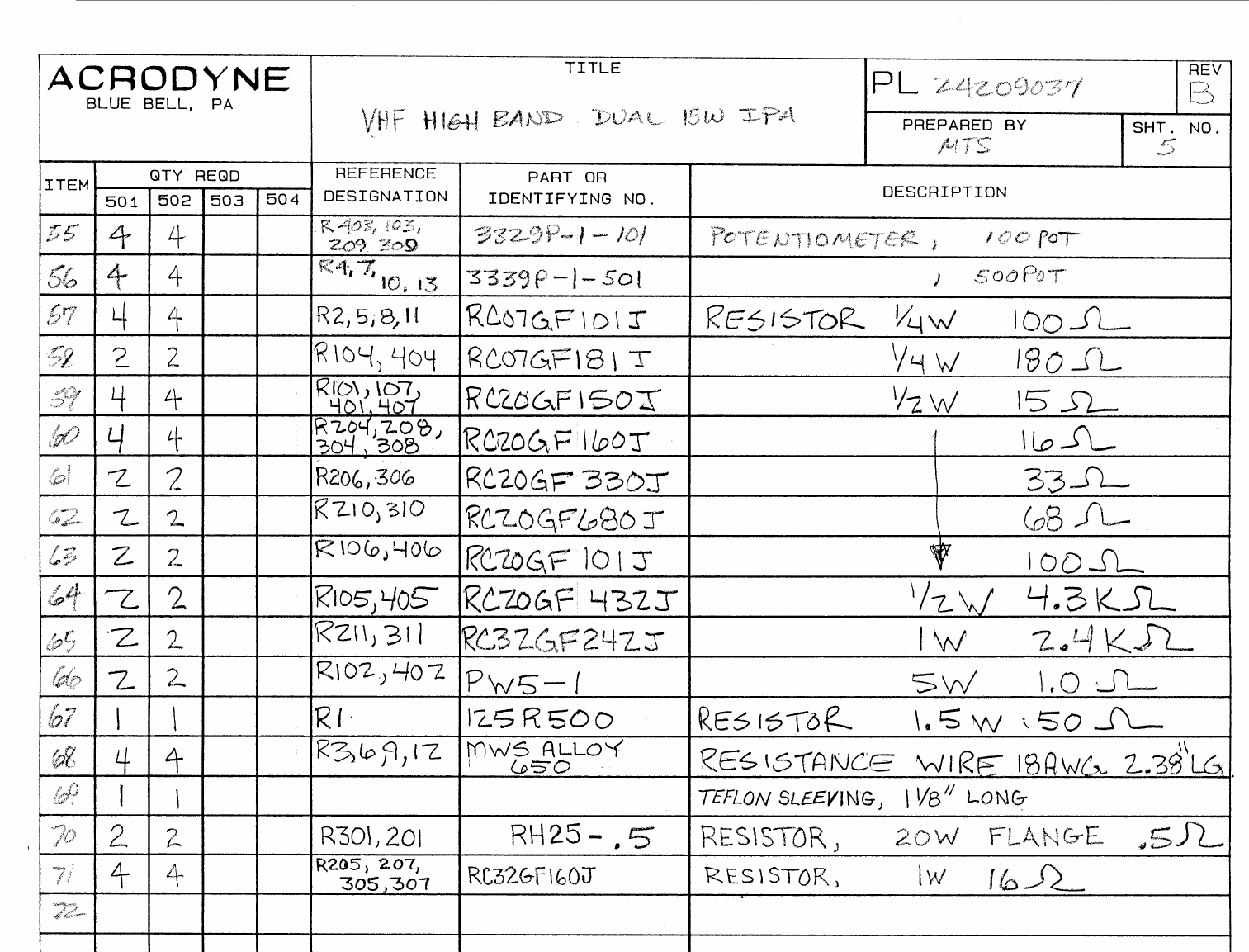
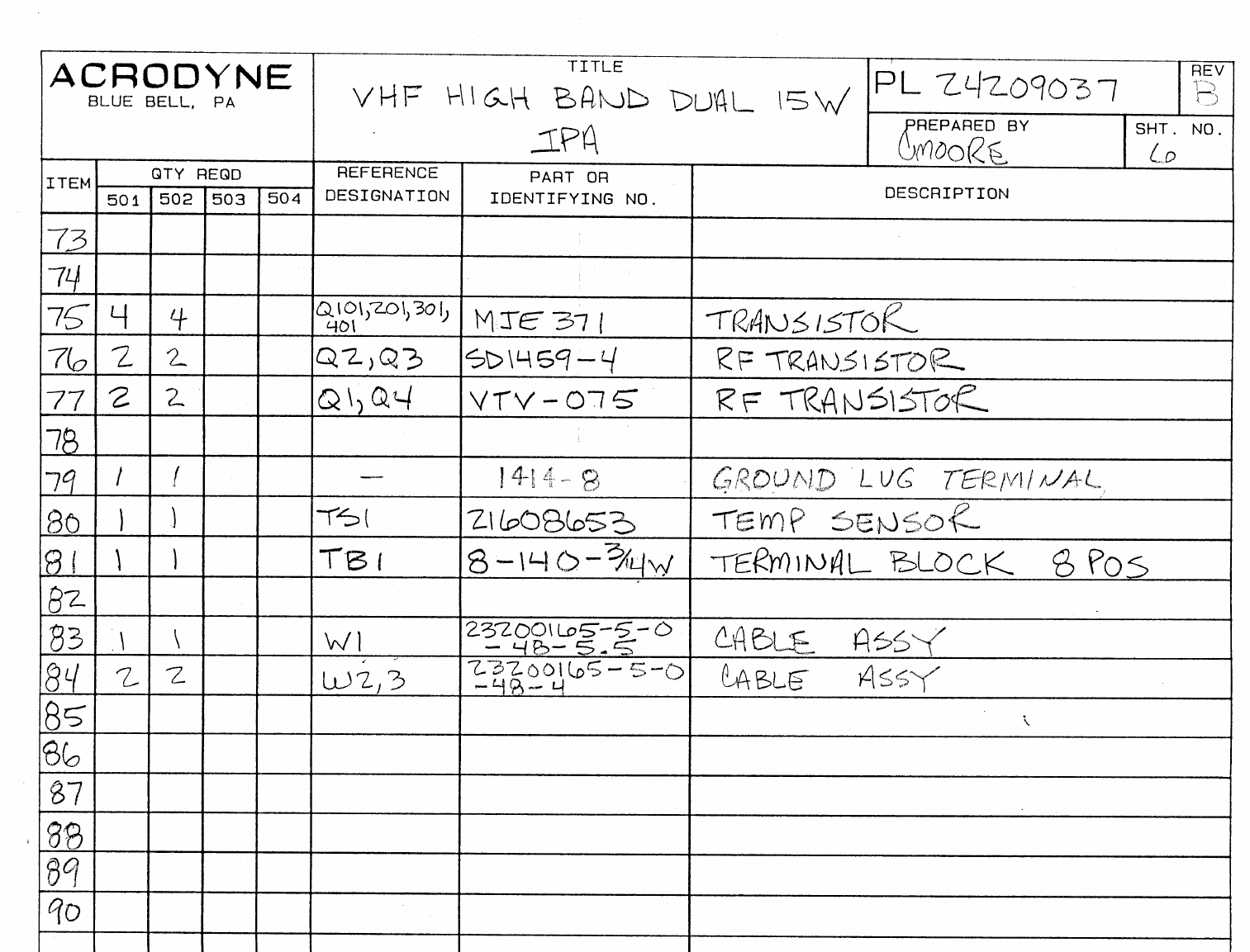
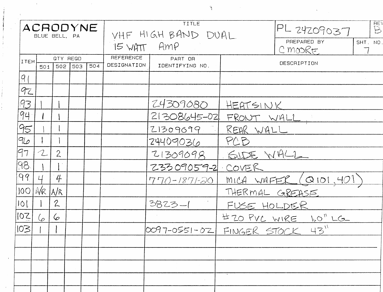
JOB NO.
NEXT ASSY.
USED ON
REF. DES.
22108988
TLH/500S
ASSY
DESCRIPTION
ECN LTR DESCRIPTION REVISED BY APPROVED BY
ACHANGED ITEM 50 TO PL1, ITEM 1 WAS 22509063 MC 11/7/95
3066 BPER ECN QTY OF ITEM 37 WAS 4, ITEM 25 WAS 23305443 HFG 4/1/98 MB 04/98
CITEM #31 WAS CHANGED TO REFF. DES. W1 & W2. MTS 08/98 MB 08/98
3205
3242 DPART NUMBERS WRONG. #24 WAS 21607579, #35 WAS 21306441-04, AND #50 WAS
PL1 JJC 10/ 06/98
ACRODYNE INDUSTRIES
516 TOWNSHIP LINE ROAD
BLUE BELL, PA. 19422
TITLE
ASSEMBLY, 600 WATT VHF
HIGH BAND AMPLIFIER
CODE IDENT
51336 DOCUMENT NUMBER
PL24209082-501 REVISION
D
PREPARED BY
C.MOORE
CHECKED BY
DATE
12/28/94
DATE
APPROVED BY
DATE
ACRODYNE
SHEET 1 OF 3

QUANTITY REQUIRED REFERENCE PART OR
ITEM -501 -502 -503 -504 DES. IDENTIFYING NUMBER DESCRIPTION VENDER
PL 24209082-501 Rev D
ACRODYNE
BLUE BELL, PA
Title
ASSEMBLY, 600 WATT
VHF HIGH BAND AMP. PREPARED BY
HFG SHEET NO.
2
1X X 22509167 WIRING DIAGRAM
2
3 1 A1 24209000 ASSEMBLY, VHF HIGH BAND LEFT 300 W AMPLIFIER
4 1 A2 24209010 ASSEMBLY, VHF HIGH BAND RIGHT 300 W AMPLIFIER
5 1 A3 22209040-501 ASSEMBLY, METER SWITCH PCB
6 1 A4 22208858-502 ASSEMBLY, CONTROL CIRRCUIT PCB
7
8
9
10
11
12
13 2 BL1,2 JD24B2 BLOWER(ROTRON MAJOR 24VDC)
14
15 1 C1 CK05BX104K CAPACITOR 0.1 UF
16 1 CR1 MB2505 DIODE
17
18
19
20 1 J4X 206036-1 CONNECTOR, 16 PIN
21 1 J5XR 22308094-01 HC CONNECTOR,(NL4MPR MODIFIED)
22 1 J5XL 22308094-02 HC CONNECTOR,(NL4MPR MODIFIED)
23
24 1 M1 24209082 METER
25 1 23305443-02 CONNECTOR BRACKET
26 2 22305362 PANEL BRACKET
27 1 22306104 TOP PANEL BRACKET
28 1 24308617-02 FRONT PANEL
29 6 609-2030 CONNECTOR, 20 CONDUCTOR RIBBON CABLE
30 4 609-2031 CLAMP, 20CONDUCTOR RIBBON CABLE
31 2 W1,2 171-20 20CONDUCTOR RIBBON CABLE
32
33
34

QUANTITY REQUIRED REFERENCE PART OR
ITEM -501 -502 -503 -504 DES. IDENTIFYING NUMBER DESCRIPTION VENDER
PL 24209082-501 Rev D
ACRODYNE
BLUE BELL, PA
Title
ASSEMBLY, 600 WATT
VHF HIGH BAND AMP. PREPARED BY
HFG SHEET NO.
3
35 1 21311127 METER FACE
36 2 8237-A-0440 STANDOFF, 2-1/2” LG., #4-40 THD.
37 1 2177 GROMMET, ½”
38
39
40 1 48-20-401-10 LATCH SOUTHCO
41 2 11402-A-1032 HANDLE
42 2 370-QD-22 SLIDE (ATTACH INNER SECTION ONLY)
43
44 2 23308003 GUIDE RAIL
45 1 22308850 MOUNTING PLATE(BLOWER)
46 2 24308010-03 DUCT PLATE
47 1 23308848-02 BLOWER END FRONT
48 1 23308848-01 BLOWER END REAR
49
50 1 PS-70-PL2 KNOB
51 2 22300398-01 METER CLIP
52 1 22308923-01 AIR BAFFLE
53
54 2 23308923-02 AIR BAFFLE
55
56
57
58
59
60
61
62