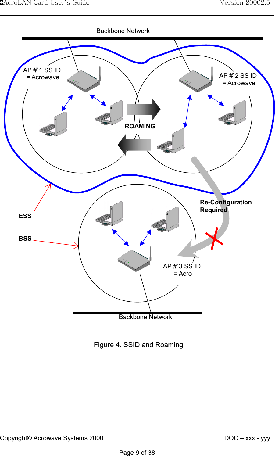
Acrowave Systems AWL-1100U DSSS WLAN IEEE802.11b USB Card User Manual

Acrowave Systems Co., Ltd DSSS WLAN IEEE802.11b USB Card Users Manual

Users Manual

!AcroLAN Card User’s Guide                                Version 20002.5Copyright© Acrowave Systems 2000 DOC – xxx - yyyPage 1 of 38Corporate HeadquartersAcrowave Systems Co. Ltd. 6Fl. Maru Building 86-6 Nonhyun-dongGangnam-gu Seoul 135-818Koreahttp://www.acrowave.comTel: 82-2-547-8778Fax: 82-2-547-4779Acrowave Systems££££Wireless LAN PC CardUser’s GuideAWL-1100C/AWL-1100PAWL-1100U/AWL-1100M
!AcroLAN Card User’s Guide                                Version 20002.5Copyright© Acrowave Systems 2000 DOC – xxx - yyyPage 2 of 38ContentsChapter 1 Introduction To The Wireless LAN1.1 What’s the Wireless LAN? …………………………………… 51.2 Wireless LAN Standard and Structure………………………… 6Chapter 2 Before You Start AcroLAN……………………………. 12Chapter 3 Installing AcroLAN Card Driver………………………13Chapter 4 Connecting the AcroLAN Card to your computer4.1 Installing AcroLAN PCMCIA Card……………………… 164.2 Installing AcroLAN PCI Card………………………….… 164.3 Installing AcroLAN USB Card………………………….… 204.4 Installing AcroLAN Mini-PCI Card …………………….… 20Chapter 5 Configuring the Wireless LAN Card5.1 Installing Network Protocols… ……...…………………………...225.2 Uninstalling AcroLAN Card Driver……………………………. 275.3 Remove AcroLAN Card from you computer………………….. 275.4 Wireless AcroLAN Card Configuration Utility………………. 30Chapter 6 Troubleshooting ……………………………………………35AppendixAppendix A Cell Planning (Radio Range) …………………………….. 37Appendix B Technical Specification …………………………………. 39Appendix C Channel Allocation ……………………………..………… 42
!AcroLAN Card User’s Guide                                Version 20002.5Copyright© Acrowave Systems 2000 DOC – xxx - yyyPage 3 of 38THE SPECIFICATIONS AND INFORMATION REGARDING THE PRODUCTS IN THIS MANUAL ARE SUBJECT TO CHANGE WITHOUTNOTICE. ALL STATEMENTS, INFORMATION, AND RECOMMENDATIONS IN THIS MANUAL ARE BELIEVED TO BE ACCURATE BUTARE PRESENTED WITHOUT WARRANTY OF ANY KIND, EXPRESS OR IMPLIED. USERS MUST TAKE FULL RESPONSIBILITY FORTHEIR APPLICATION OF ANY PRODUCTS.THE SOFTWARE LICENSE AND LIMITED WARRANTY FOR THE ACCOMPANYING PRODUCT ARE SET FORTH IN THEINFORMATION PACKET THAT SHIPPED WITH THE PRODUCT AND ARE INCORPORATED HEREIN BY THIS REFERENCE. IF YOUARE UNABLE TO LOCATE THE SOFTWARE LICENSE OR LIMITED WARRANTY, CONTACT YOUR ACROWAVE REPRESENTATIVEFOR A COPY.The following information is for FCC compliance of Class B devices:This equipment has been tested and found to comply with the limits for a Class B digital device, pursuant to Part 15 of theFCC Rules. These limits are designed to provide reasonable protection against harmful interference in a residentialinstallation. This equipment generates, uses and can radiate radio frequency energy and, if not installed and used inaccordance with the instructions, may cause harmful interference to radio communications. However, there is noguarantee that interference will not occur in a particular installation. If this equipment does cause harmful interference toradio or television reception, which can be determined by turning the equipment off and on, the user is encouraged to tryto correct the interference by one or more of the following measures:lReorient or relocate the receiving antenna.lIncrease the separation between the equipment and receiver.lConnect the equipment into an outlet on a circuit different from that to which the receiver is connected.lConsult the dealer or an experienced radio/TV technician for help.This device complies with Part 15 of the FCC Rules and with RSS-210 of Industry Canada.Operation is subject to the following two conditions:(1) this device my not cause harmful interference, and(2) this device must accept any interference received, including interference that may cause undesiredoperation.This equipment complies with FCC RF radiation exposure limits set forth for an uncontrolled environment.This equipmentmust be installed and operated with a minimum distance of 20 centimeters between the radiator and your body.Modifications to this product not authorized by Acrowave Systems Co., Ltd. could void the FCC approval and negate your authority tooperate the product.NOTWITHSTANDING ANY OTHER WARRANTY HEREIN, ALL DOCUMENT FILES AND SOFTWARE OF THESE SUPPLIERS AREPROVIDED “AS IS” WITH ALL FAULTS. ACROWAVE AND THE ABOVE-NAMED SUPPLIERS DISCLAIM ALL WARRANTIES,EXPRESSED OR IMPLIED, INCLUDING, WITHOUT LIMITATION, THOSE OF MERCHANTABILITY, FITNESS FOR A PARTICULARPURPOSE AND NONINFRINGEMENT OR ARISING FROM A COURSE OF DEALING, USAGE, OR TRADE PRACTICE.IN NO EVENT SHALL ACROWAVE OR ITS SUPPLIERS BE LIABLE FOR ANY INDIRECT, SPECIAL, CONSEQUENTIAL, ORINCIDENTAL DAMAGES, INCLUDING, WITHOUT LIMITATION, LOST PROFITS OR LOSS OR DAMAGE TO DATA ARISING OUT OFTHE USE OR INABILITY TO USE THIS MANUAL, EVEN IF ACROWAVE OR ITS SUPPLIERS HAVE BEEN ADVISED OF THEPOSSIBILITY OF SUCH DAMAGES.AcroLAN, the Acrowave logo are registered trademarks of Acrowave Systems Co., Ltd. or its affiliates in the Korea, U.S. and certain othercountries. All other trademarks mentioned in this document are the property of their respective owners. The use of the word partner doesnot imply a partnership relationship between Acrowave and any of its resellers.Using the Acrowave AcroLAN CardCopyright© 2000, Acrowave Systems Co., LtdAll rights reserved.
!AcroLAN Card User’s Guide                                Version 20002.5Copyright© Acrowave Systems 2000 DOC – xxx - yyyPage 4 of 38Chapter 1 Introduction To The Wireless LANA wireless LAN (WLAN) is a flexible data communication system implemented as anextension to, or as an alternative for, a wired LAN within a building or campus. Usingelectromagnetic waves, WLANs transmit and receive data over the air, minimizing theneed for wired connections. Thus, WLANs combine data connectivity with user mobility,and, through simplified configuration, enable movable LANs. WLANs have gained strongpopularity in a number of vertical markets, including the health-care, retail,manufacturing, warehousing, and academic arenas. These industries have profited fromthe productivity gains of using hand-held terminals and notebook computers to transmitreal-time information to centralized hosts for processing. Today WLANs are becomingmore widely recognized as a general-purpose connectivity alternative for a broad rangeof business customers.1.1 What’s Wireless LAN?Wireless LANs use electromagnetic airwaves (radio and infrared) to communicateinformation from one point to another without relying on any physical connection. Radiowaves are often referred to as radio carriers because they simply perform the function ofdelivering energy to a remote receiver. The data being transmitted is superimposed onthe radio carrier so that it can be accurately extracted at the receiving end. This isgenerally referred to as modulation of the carrier by the information being transmitted.Once data is superimposed (modulated) onto the radio carrier, the radio signal occupiesmore than a single frequency, since the frequency or bit rate of the modulatinginformation adds to the carrier.Multiple radio carriers can exist in the same space at the same time without interferingwith each other if the radio waves are transmitted on different radio frequencies. Toextract data, a radio receiver tunes in (or selects) one radio frequency while rejecting allother radio signals on different frequencies.In a typical WLAN configuration, a transmitter/receiver (transceiver) device, called anaccess point, connects to the wired network from a fixed location using standardEthernet cable. At a minimum, the access point receives, buffers, and transmits databetween the WLAN and the wired network infrastructure. A single access point cansupport a small group of users and can function within a range of less than one hundredto several hundred feet. The access point (or the antenna attached to the access point)is usually mounted high but may be mounted essentially anywhere that is practical aslong as the desired radio coverage is obtained.End users access the WLAN through wireless LAN adapters, which are implemented asPC cards in notebook computers, or use PCI adapters in desktop computers. WLANadapters provide an interface between the client network operating system (NOS) andthe airwaves (via an antenna). The nature of the wireless connection is transparent tothe NOS.1.2 Wireless LAN Standard and StructureƒƒƒƒWireless LAN Standard – IEEE802.11bThe widespread acceptance of WLANs depends on industry standardization to ensureproduct compatibility and reliability among the various manufacturers. The Institute of
!AcroLAN Card User’s Guide                                Version 20002.5Copyright© Acrowave Systems 2000 DOC – xxx - yyyPage 5 of 38Electrical and Electronics Engineers (IEEE) ratified the original 802.11 specifications in1997 as the standard for wireless LANs. That version of 802.11 provides for 1 Mbps and2 Mbps data rates and a set of fundamental signaling methods and other services. Themost critical issue affecting WLAN demand has been limited throughput. The data ratessupported by the original 802.11 standard are too slow to support most general businessrequirements and have slowed adoption of WLANs. Recognizing the critical need tosupport higher data-transmission rates, the IEEE recently ratified the 802.11b standard(also known as 802.11 High Rate) for transmissions of up to 11 Mbps.With 802.11b, WLANs will be able to achieve wireless performance and throughputcomparable to wired Ethernet. Outside of the standards bodies, wireless industry leadershave united to form the Wire-less Ethernet Compatibility Alliance (WECA).WECA’s mission is to certify cross-vendor interoperability and compatibility of IEEE802.11b wireless networking products and to promote that standard for the enterprise,the small business, and the home. Members include WLAN semiconductormanufacturers, WLAN providers, computer system vendors, and software makers.ƒƒƒƒWireless LAN Network Equipment802.11 defines two pieces of equipment, a wireless station, which is usually a PCequipped with a wireless network interface card (NIC), and an access point (AP), whichacts as a bridge between the wireless and wired networks. An access point usuallyconsists of a radio, a wired network interface (e.g., 802.3), and bridging softwareconforming to the 802.1d bridging standard. The access point acts as the base stationfor the wireless network, aggregating access for multiple wireless stations onto the wirednetwork. Wireless end stations can be 802.11 PC Card, PCI. ƒƒƒƒWireless LAN Network ConfigurationThe 802.11 standard define two modes: infrastructure mode and ad hoc mode (orindependent or peer-to-peer).lAd Hoc ModeAd hoc mode (also called peer-to-peer mode or an Independent BasicService Set, or IBSS) is simply a set of 802.11 wireless stations thatcommunicate directly with one another without using an access point or anyconnection to a wired network. This mode is useful for quickly and easilysetting up a wireless network anywhere that a wireless infrastructure does notexist or is not required for services, such as a hotel room, convention center,or airport, or where access to the wired network is barred (such as forconsultants at a client site).Independent BasicService Set (IBSS)
!AcroLAN Card User’s Guide                                Version 20002.5Copyright© Acrowave Systems 2000 DOC – xxx - yyyPage 6 of 38Figure 1. Ad Hoc ModelInfrastructure ModeIn infrastructure mode, the wireless network consists of at least one accesspoint connected to the wired network infrastructure and a set of wireless endstations. This configuration is called a Basic Service Set (BSS). An ExtendedService Set (ESS) is a set of two or more BSSs forming a single sub-network.Since most corporate WLANs require access to the wired LAN for services(file servers, printers, Inter-net links) they will operate in infrastructure mode.Figure 2. Infrastructure ModeƒƒƒƒRoamingWireless communication is limited by how far signals carry for given power output.WLANs use cells, called microcells, similar to the cellular telephone system to extendthe range of wireless connectivity. At any point in time, a mobile PC equipped with aWLAN adapter is associated with a single access point and its microcell, or area ofcoverage. Individual microcells overlap to allow continuous communication within wirednetwork. They handle low power signals and “hand off” users as they roam through agiven geographic area.The 802.11 MAC layer is responsible for how a client associates with an access point.When an 802.11 client enters the range of one or more APs, it chooses an access pointto associate with (also called joining a Basic Service Set), based on signal strength andDistribution System (DS)Service Set (SS) – Multiplele CellsAccess Point (AP)Ethernet (802.3)
!AcroLAN Card User’s Guide                                Version 20002.5Copyright© Acrowave Systems 2000 DOC – xxx - yyyPage 7 of 38observed packet error rates. Once accepted by the access point, the client tunes to theradio channel to which the access point is set. Periodically it surveys all 802.11 channelsin order to assess whether a different access point would provide it with betterperformance characteristics. If it determines that this is the case, it reassociates with thenew access point, tuning to the radio channel to which that access point is set.Reassociation usually occurs because the wireless station has physically moved awayfrom the original access point, causing the signal to weaken. In other cases,Reassociation occurs due to a change in radio characteristics in the building, or duesimply to high network traffic on the original access point. In the latter case this functionis known as “load balancing,” since its primary function is to distribute the total WLANload most efficiently across the available wireless infrastructure. This process ofdynamically associating and reassociating with APs allows network managers to set upWLANs with very broad coverage by creating a series of overlapping 802.11b cellsthroughout a building or across a campus. To be successful, the IT manager ideally willemploy “channel reuse,” taking care to set up each access point on an 802.11 DSSSchannel that does not overlap with a channel used by a neighboring access point.Figure3.RoamingBackbone NetworkAccess Point (AP)Inter-Cell Roaming
!AcroLAN Card User’s Guide                                Version 20002.5Copyright© Acrowave Systems 2000 DOC – xxx - yyyPage 8 of 38ƒƒƒƒBSS, ESS and SS IDThe basic service set (BSS) is the basic building block of WLAN network. MinimumWLAN BSS may be consist of only two stations. Using access point (AP) and networkdistribution systems (DS), WLAN service set can be extended arbitrary size – extendedservice set (ESS). Each service set has its network ID (SSID). All the service sets withinan ESS network can have same service ID so that the ESS can support inter-cellROAMING.
!AcroLAN Card User’s Guide                                Version 20002.5Copyright© Acrowave Systems 2000 DOC – xxx - yyyPage 9 of 38Figure 4. SSID and RoamingBackbone NetworkAP #`2 SS ID= AcrowaveROAMINGAP #`1 SS ID= AcrowaveAP #`3 SS ID=AcroESSBSSBackbone NetworkRe-ConfigurationRequired
!AcroLAN Card User’s Guide                                Version 20002.5Copyright© Acrowave Systems 2000 DOC – xxx - yyyPage 10 of 38Chapter 2 Before You Start AcroLANTo use the AcroLAN adapter with a computing device (desktop personal computer,notebook, laptop computer, portable or hand-held device), the device must be equippedwith an internal or external PC Card Type II or Type III slot. All drivers and supportingsoftware (card and socket services) for the client adapter slot must be loaded andconfigured.Ask your system administrator for the following information, which you may need toprovide during driver installation:• Your Wireless Client Name• Your Wireless SSID• Your computer's unique client name and workgroup name• For Windows NT, a free interrupt and I/O address.• For your network account, your user name and password• If you’re not using a DHCP server, your IP address, gateway address, and subnetmaskAfter unpacking the card, make sure the following items are present and in goodcondition:• Acrowave AcroLAN AWL-1100 Series PC Card Adapter• AWL-1100 Series install software and documentation CD for WindowsIf any item is damaged or missing, contact your PC Card adapter supplier. Save all theshipping and the packing material to repack the unit should service be required.CautionBefore you start, close all working windows and backup important data.
!AcroLAN Card User’s Guide                                Version 20002.5Copyright© Acrowave Systems 2000 DOC – xxx - yyyPage 11 of 38Chapter 3 Installing the PC/PCI Card Adapter on a Windows OSThis section provides instructions for installing a PC/PCI adapter on a computer usingone of the Windows operating systems.Whatever operating systems(Windows 95/98/ME/2000/XP) you use the installationprocedures are all same. But, PCI card does not support for Windows XP. CautionThe following procedures and physical connections apply generally to normaland conventional client adapter slots. In the cases of custom or non-conventionalequipment, be alert to possible differences in client adapter slot configurations.3.1 Installing PC Card AdapterBefore you begin, examine the client adapter. One end is a dual-row, 68-pin clientadapter connector. This side will be inserted into the client adapter slot with the logo onthe client adapter facing up. The card is keyed so it can be inserted only one way intothe slot.The client adapter can be connected to a client adapter Type II slot. This includes slotsthat support both Type II and Type III cards.CautionDo not force the client adapter into the slot. Forcing it will damage both theclient adapter and the slot. If the client adapter does not go in easily, remove the cardand reinsert it.
!AcroLAN Card User’s Guide                                Version 20002.5Copyright© Acrowave Systems 2000 DOC – xxx - yyyPage 12 of 383.1.1 Installing the PC Card Driver for Windows Operating Systems××××Windows95, 98, 2000, ME, XPIf the operating system on your computer is Windows, follow these steps.If you insert the AcroLAN software anddocumentation CD for Windows, the Windows automatically runs AcroLAN setupprogram and a dialog box appears.( Some CDs may not run automatically, in this case execute “Setpu.exe” file located atthe Card setup directory of CD.)It takes a few seconds for copying theutility files and then click on Finish to complete the installation.STEP 1STEP 2
!AcroLAN Card User’s Guide                                Version 20002.5Copyright© Acrowave Systems 2000 DOC – xxx - yyyPage 13 of 38
!AcroLAN Card User’s Guide                                Version 20002.5Copyright© Acrowave Systems 2000 DOC – xxx - yyyPage 14 of 38Chapter 4 Connecting the AcroLAN Card to your computerCautionThe following procedures and physical connections apply generally to normaland conventional client adapter slots. In the cases of custom or non-conventionalequipment, be alert to possible differences in client adapter slot configurations.4.1 Installing AcroLAN PCMCIA CardBefore you begin, examine the card. One end is a dual-row, 68-pin client adapterconnector. This side will be inserted into the client adapter slot with card’s logo facingup. The card is keyed so it can be inserted only one way into the slot. The client adapter can be connected to a client adapter Type II slot. This includes slotsthat support both Type II and Type III cards.CautionDo not force the card into the slot. Forcing it will damage both the client adapterand the slot. If the client adapter does not go in easily, remove the card and reinsert it. 4.2 Installing AcroLAN PCI CardThis section describes the procedures for installing the client adapter.Before You StartFor the client adapter to be used with a computing device, the device must be equippedwith a PCI or ISA expansion slot. Check the documentation that came with yourcomputer for details on the differences between PCI and ISA expansion slots.Ask your system administrator for the following information, which you may need toprovide during driver installation:• Your Wireless Client Name• Your Wireless SSID• Your computer's unique client name and workgroup name• For your network account, your user name and password• If you’re not using a DHCP server, your IP address, gateway address, and subnetmaskAfter unpacking the client adapter, make sure the following items are present and in
!AcroLAN Card User’s Guide                                Version 20002.5Copyright© Acrowave Systems 2000 DOC – xxx - yyyPage 15 of 38good condition:• AcroLAN AWL-1100P Series PCI Client Adapter• Standard 2 dBi dipole antenna• AWL-1100P Series software and documentation CD for Windows 95/98 Windows ME,Windows 2000 Installing the PCI Client AdapterIf any item is damaged or missing, contact your client adapter supplier. Save all shippingand packing material in order to repack the unit should service be required.This section provides instructions for installing a client adapter on a computer using oneof the Windows operating systems.Before you begin, examine the client adapter. The antenna connector and Status andActivity LEDs will face out of your computer, and will be visible when you put the coverback on. The bottom edge of the card is the connector you will insert into an emptyexpansion slot in your computer.4.2.1 Installing PCI Card Adapter1. Turn off the computer and all its components. 2. Remove the computer cover. 3. Remove the screw from the top of the CPU back panel above an empty expansionslot. This screw is used to hold the metal bracket on the back panel. 4. Tilt the client adapter to allow the antenna connector and LED lights to slip throughthe opening in the CPU back panel.5. Press the client adapter into the empty slot until its connector is firmly seated.
!AcroLAN Card User’s Guide                                Version 20002.5Copyright© Acrowave Systems 2000 DOC – xxx - yyyPage 16 of 38CautionDo not force the client adapter into the slot. Forcing it will damage both the cardand the slot. If the card does not go in easily, remove the card and reinsert it. 6. Reinstall the screw to the top of the CPU back panel. 7. The client adapter comes with one 2dBi dipole antenna. With the unit powered off,attach the antenna to the antenna connector on the client adapter.
!AcroLAN Card User’s Guide                                Version 20002.5Copyright© Acrowave Systems 2000 DOC – xxx - yyyPage 17 of 38CautionDo not over-tighten the antenna connector; finger-tight is sufficient. Position theantenna vertically for best omni-directional signal reception.4.3 Installing AcroLAN USB CardAWL-1100U is Wireless LAN Adapter and it provide USB1.1 host interface. USB canuse both notebook PC and desktop PC. Operation and installation method is samewith PC card.To install AcroLAN USB Card, first connect one end of the USB cable to the card. Then,
!AcroLAN Card User’s Guide                                Version 20002.5Copyright© Acrowave Systems 2000 DOC – xxx - yyyPage 18 of 38connect the other end of the USB cable to the USB port on your computer. Since thecard gets its power from the PC’s USB port, there is no external power adapter. ThePower LED should light up green when the Card is attached and the PC is on.4.4 Installing AcroLAN Mini-PCI CardAWL-1100M is Mini PCI type card and it can use at notebook PC. Antenna is located atthe side of monitor and it can improve link quality.It is very convenient to use becausethe card is installed inside PC. It satisfy IEEE802.11b standard and support maximum11Mbps data rate. It support also Ad-Hoc(Peer to Peer) and Infra structure mode. Installation procedure of Mini PCI card is as below.Install driver program first before insert card. Turn off PC power and insert card to PC. Turn on PC power then it will automatically run installation program.CautionPlease check the availability of your PC has Mini PCI slot before you purchase Mini PCIcard. Most of the case Mini PCI will be installed at manufacturing status.
!AcroLAN Card User’s Guide                                Version 20002.5Copyright© Acrowave Systems 2000 DOC – xxx - yyyPage 19 of 38Chapter 5 Configuring the AcroLAN CardIf you have connected Wireless LAN card successfully, illuminating LED and Soundconfirms the detection of your card. Also you will see its icon on the right bottom of yourscreen.If you install Acrowave’s wireless LAN card for the first time all the setup process runsautomatically. If you reinstall, the install program asks next two files folder position andyou should select same as the below:lLocation designation of inf fileWindows98, ME(filename : AcrowavePRISMNIC.inf)C: \WINDOW\infWindows 95, 2000, XP(filename : PRISMNIC.inf)C: \WINDOWS\inflLocation designation of driver fileWindows 95, 98, ME (filename : PRISMNDS.sys)C: \WINDOWS\SYSTEMWindows 2000, XP (filename : PRISMNDS.sys) C: \WINDOWS\SYSTEM\DriversAnd then the install program asks whether you want to reboot your computer. At thistime you should select No in order to complete the installation correctly.Left-click My Computer icon on your desktop and select Properties. Open DeviceManager In the Hardware Tab. If you find yellow (?) sign on the adaptor, it shows theinstallation is not successful. Select the adaptor and click on Remove. Restart yourcomputer after uninstalling the driver to make the change effective.5.1 Installing Network ProtocolsProtocols are necessary for computers to be recognized on your network. Windows2000 and XP users need to check their Windows User Guides for protocol installation.From the Start Menu, select Settings and bring up the Control Panel. From the ControlPanel, double-click on the Network icon. The Network box appears and you see threemain tabs; Configuration, Identification, Access control.Select Wireless LAN Card on the configuration tab and then click the Add button.Highlight Protocol, and click the Add button.Select Microsoft from the list of “Manufacturers” and TCP/IP from the list of “NetworkProtocols” Click the OK button to close the Network window. Windows may startcopying some files and ask you for your Windows installation files at this time. After thefiles are copied Windows may ask you to restart. Click Yes to restart and complete theinstallation process.
!AcroLAN Card User’s Guide                                Version 20002.5Copyright© Acrowave Systems 2000 DOC – xxx - yyyPage 20 of 38CautionThis Process could cause serious problem on your network if you edit wrong data. So, if you donot know how to configure your network option, ask for help your network administrator.Click on the TCP/IP option for setting the IP address for your computer. You can select eitherStatic or DHCP setting. If you use static IP address then enter the IP value assigned for you, andSubnet masking, DNS, Domain/Workgroup name, Gateway address value.IP AddressIP AddressIP AddressIP Address
!AcroLAN Card User’s Guide                                Version 20002.5Copyright© Acrowave Systems 2000 DOC – xxx - yyyPage 21 of 38Gateway AddressGateway AddressGateway AddressGateway Address
!AcroLAN Card User’s Guide                                Version 20002.5Copyright© Acrowave Systems 2000 DOC – xxx - yyyPage 22 of 38After setting these parameters appropriately, click on OK to return Network ComponentType and you can select the File and Printer Sharing options as well as the Access toyour computer by other users connected to that network by setting the computersharing options.Click on OK.DNSDNSDNSDNS
!AcroLAN Card User’s Guide                                Version 20002.5Copyright© Acrowave Systems 2000 DOC – xxx - yyyPage 23 of 38Screen message “Do you want to restart your computer” will pop up. Select Yes. It willshut down your computer and will restart.
!AcroLAN Card User’s Guide                                Version 20002.5Copyright© Acrowave Systems 2000 DOC – xxx - yyyPage 24 of 385.2 Uninstalling AcroLAN Card DriverIf you want to uninstall the PC card, click on the control panel. Select the Add/RemovePrograms. Click on the Acrowave 11Mbps Wireless LAN and click on Add/Removebutton. Uninstall Shield removes the software successfully. And then, click System icon in the control panel and removes the ACROWAVE 11MbpsWireless PC Card adapter under the Network adapters.5.3 Remove PC Card from PC card socket5.3.1 Remove PCMCIA AcroLAN Card /PCI AcroLAN CardIf you want to extract PC card from PC card socket, click on PC card information icon.Click on Socket Status window and select ACROWAVE 11Mbps Wireless PC carsadapter and click on Stop button.After a few second, screen message “You can remove this device safely” will pop up.5.3.2 Remove USB AcroLAN CardPC may shut down or malfunction if you pull out USB connector from PC without properprocedure. It will be okay if you follow as below.
!AcroLAN Card User’s Guide                                Version 20002.5Copyright© Acrowave Systems 2000 DOC – xxx - yyyPage 25 of 38Above utility window will be pop up when you click PC monitor shape green icon.Select “ Radio Disable”.Then PC icon will be display with X and it means Wireless LAN operation is stoped.After PC monitor shape green icon go out of sight, Pull out USB connector from PC.If you want to use again then connect USB port to PC and select “Enable Radio” at utilitywindow.5.3.3 Remove Mini-PCI AcroLAN CardBe sure to turn off PC power before remove.
!AcroLAN Card User’s Guide                                Version 20002.5Copyright© Acrowave Systems 2000 DOC – xxx - yyyPage 26 of 38
!AcroLAN Card User’s Guide                                Version 20002.5Copyright© Acrowave Systems 2000 DOC – xxx - yyyPage 27 of 385.4 AcroLAN Configuration UtilityAcrowave install shied program installs wireless LAN driver program and ConfigurationUtility program. You can see the icon at the right bottom of your screen. Click on thaticon will show you the screen as show below.Status shows wireless LAN card’s MAC address information.Current Tx Rate shows transmit data rate.Current Channel shows selected channel number.Channel number is the channel available for the communications between the clientand AP or between the clients only. In case of the Infrastructure Network Mode, thechannel number scanned automatically, while in case of the Ad-hoc Network Mode, thechannel number is set by the client and can be changed by the client user.If you click on Rescan button, LAN card program searches other new channel thatcurrently used one.Throughput (Byte/sec) shows transmit/receive data rate.Link Quality shows measured radio link quality. If the link quality is bad, your computermay not communicate with other client computers. Otherwise (; fair, good…), there isno problem to communicate with other clients.Signal Strength is similar to Link Quality information but slightly differ from it. ButWireless Link StatusWireless Link StatusWireless Link StatusWireless Link Status
!AcroLAN Card User’s Guide                                Version 20002.5Copyright© Acrowave Systems 2000 DOC – xxx - yyyPage 28 of 38usually, the quality level moves simultaneous with the Link Quality level.Network Type : You can select wireless LAN network mode – Infrastructure(AccessPoint) or Ad-hoc(Peer-to-Peer) modeInfrastructure ModeThis mode is used to set up a connection to a wired Ethernet network. This moderequires an ACROLAN Access Point to gain access to the wired network.Ad Hoc ModeThis mode is used to set up a small, temporary network between two or morecomputers. For example, you might set up an ad hoc network between computers in aconference room so users can share information in a meeting.Network Name(SSID) :The Service Set Identifier (SSID) controls access to a given wirelessnetwork. This value MUST match the SSID of any and all AcroLAN Access Points that you wantto communicate with. If the value does not match, access to the system is not granted. The SSIDcan be up to 32 case-sensitive characters.Transmit Rate: The transmission rate at which the data packets are transmitted by theclient or AP. You can set this value to 1~2Mbps, 5.5Mbps, 11Mbps or Fully Automatic. Power Save Enabled : Power Saving Mode. Currently, the Power Save mode does notsupported.After changing the setting in the Configuration change dialog box, click on ApplyChanges button. It takes a few seconds to set changes that you made. Network ConfigurationNetwork ConfigurationNetwork ConfigurationNetwork Configuration
!AcroLAN Card User’s Guide                                Version 20002.5Copyright© Acrowave Systems 2000 DOC – xxx - yyyPage 29 of 38In order to do secure communication over the wireless LAN network, wireless LANmodule provides encryption function - WEP. There are two ways to generate WEP key. This key is an important in protecting the illegal access to the wireless networks.If you want to use WEP function, the AP also set the same WEP key value with you.Andalltheuserswhowanttocommunicatewithyoumustusesamekeywitheachother.You can select WEP key Disable in Configuration dialog box, the communicationbetween clients and AP does not secure.EncryptionEncryptionEncryptionEncryption - WEP - WEP - WEP - WEP
!AcroLAN Card User’s Guide                                Version 20002.5Copyright© Acrowave Systems 2000 DOC – xxx - yyyPage 30 of 38There are two ways to generate the WEP key. One is by entering any text in thePassphrase. And click on Generate button. It will generate four WEP keys; Key 1, Key 2,Key 3, Key 4. You can select any key for the security. If you do not select any key, Key 1is selected in default.The other way is by entering Key value directly from the keyboard. Select the Keynumber and use that Key for accessing the AP. If the Key is not entered correctly, aclient cannot access any other client or AP. This Key value protects the illegal access tothe wireless network resources. As the wireless channel is more prone to the illegalaccess, WEP provides the users safe wireless LAN network access.CautionIf you use WEP function, your network throughput degrade
!AcroLAN Card User’s Guide                                Version 20002.5Copyright© Acrowave Systems 2000 DOC – xxx - yyyPage 31 of 38Chapter 6 TroubleshootingIn this chapter, we have listed various problems that you may encounter during theinstallation and have also listed possible solutions.£Change your location or the location of the antenna by a few feet and try again.£Make sure the client adapter card is securely inserted in the expansion slot.£Make sure the antenna is securely attached.£Make sure that your computers SSID have the same one with other clients.( Set all clients to the same channel number in case of Ad-hoc network mode.( Make sure that you are with in the range of an AP. If your computer cannot beassociated with any AP, it cannot communicate with other clients.( Make sure the antenna is securely attached.!(Youcan communicate with other clients but air link quality is not good so datatransferred slowly. In this case, you may move your computer or wireless LAN cardantenna to higher position than current state or closer position with AP.!(Makesure that the PC card is started as automatic in the device applet of the Controlpanel.£Double click on the PC card icon in the Control panel. Click on AcroLAN adapterand then click on the properties button. It should say that the driver startedcorrectly.£Make sure the drivers were installed correctly. If there is some warning or error,uninstall drivers and software through Add/Remove Program, remove the WirelessLAN card and reinstall the drivers following the manual.£Make sure that the client computer is with in the range of an AP and uses sameSSID with you.The system tray wireless monitor icon The system tray wireless monitor icon The system tray wireless monitor icon The system tray wireless monitor icon   is always red is always red is always red is always redThe system tray wireless monitor icon The system tray wireless monitor icon The system tray wireless monitor icon The system tray wireless monitor icon   is always yellow is always yellow is always yellow is always yellowCannot find wireless monitor icon Cannot find wireless monitor icon Cannot find wireless monitor icon Cannot find wireless monitor icon   in the taskbarin the taskbarin the taskbarin the taskbarCannot connect to some computersCannot connect to some computersCannot connect to some computersCannot connect to some computers
!AcroLAN Card User’s Guide                                Version 20002.5Copyright© Acrowave Systems 2000 DOC – xxx - yyyPage 32 of 38£Make sure that your TCP/IP is set properly and correctly.
!AcroLAN Card User’s Guide                                Version 20002.5Copyright© Acrowave Systems 2000 DOC – xxx - yyyPage 33 of 38AppendixAppendix A Cell Planning (Radio Range)This section provides general guidelines on factors that influence network performanceCell Site SurveyBecause of differences in component configuration, placement and physicalenvironment, every network application is a unique installation. Before installing thesystem, users should perform a site survey to determine the optimum utilization ofnetworking components and to maximize range, coverage and network performance.Here are some operating and environmental conditions you should consider:•Data RatesRadio signal sensitivity and range are inversely proportional to data bit rates. Themaximum radio range is achieved at the lowest workable data rate. There will be adecrease in receiver threshold sensitivity as the radio data rate increases.•Antenna Type and Placement(PCI card only)Proper antenna configuration is a critical factor in maximizing radio range. As a generalguide, range increases in proportion to antenna height. For a detailed explanation ofantenna types and configurations along with guidelines on selecting antennas forspecific environments, see the documentation that comes with your antenna.•Physical EnvironmentsClear or open areas provide better radio range than closed or filled areas. Also, the lesscluttered the work environment, the greater the range.•ObstructionsA physical obstruction such as metal shelving or a steel pillar can hinder theperformance of the client adapter. Avoid locating the computing device in a locationwhere there is a metal barrier between the sending and receiving antennas.•Building MaterialsRadio penetration is greatly influenced by the building material used in construction. Forexample, drywall construction allows greater range than concrete blocks. Metal or steelconstruction is a barrier to radio signals.Enhancing CoverageThe system architecture options of the wireless station and AcroLAN Access Pointsprovide for a variety of coverage alternatives and flexibility. The system can be designedto provide a wide coverage area with minimal overlap or coverage with heavy overlap.The latter improves system performance and protection against downtime in the event ofa component failure. By arranging the AcroLAN Access Points so the overlap incoverage area is minimized, a large area can be covered with minimal system cost. Thetotal bandwidth available to each mobile station will depend on the amount of data each
!AcroLAN Card User’s Guide                                Version 20002.5Copyright© Acrowave Systems 2000 DOC – xxx - yyyPage 34 of 38mobile station desires to transfer and the number of stations located in each cell.Seamless roaming is supported as a mobile station moves in and out of range of eachAcroLAN Access Point, thereby maintaining a constant connection to the wired LAN.Each device in the radio network must be configured with the same Service Set Identifier(SSID) to provide the roaming capability. Multiple systems can operate in the samevicinity. The architecture provides multiple channels, which can coexist in the same areawith virtually no interference to each other. In this mode, each system must beconfigured with different Service Set Identifiers (SSID) and different channels, whichprevent clients from roaming to AcroLAN Access Points of a different wireless system.
!AcroLAN Card User’s Guide                                Version 20002.5Copyright© Acrowave Systems 2000 DOC – xxx - yyyPage 35 of 38Appendix B Technical SpecificationsSupported Operating SystemsWindows 95, Windows 98, Windows 2000, Windows ME, Windows XPRadio SpecificationsItem Specification DescriptionRadio TypeDirect SequenceSpread-Spectrum(DSSS)2.4 GHz ISM BandOperating Frequency 2400-2483.5 MHzNorth American, ETSI, andJapan channel coverage, factoryconfigurableFCC ID FCC approvalChanneling 5 MHz increments Programmable for IEEE 802.11bType of ModulationBPSK 1 Mbit/sQPSK 2 Mbit/sCCK 5.5 and 11 Mbits/sNominal 10 MHz BW(-6 dB)Receiver sensitivity–87 dBm @ 1 Mbps–85 dBm @ 2 Mbps–84 dBm @ 5.5 Mbps–81 dBm @ 11 Mbps
!AcroLAN Card User’s Guide                                Version 20002.5Copyright© Acrowave Systems 2000 DOC – xxx - yyyPage 36 of 38Power Requirements-PCCardSpecification ValueOperational Voltage 3.3V ± 0.25VReceive Mode Current 250 mA (200 mA typically)High Power Transmit Mode Current 400 mA (370 mA typically)Sleep Mode Current 30 mA typically- PCI CardSpecification ValueOperational Voltage 5.0V ± 0.25VReceive Mode Current 250 mA (200 mA typically)High Power Transmit Mode Current 470 mA (450 mA typically)Sleep Mode Current 40 mA typically-USBCardSpecification ValueOperational Voltage 5.0V ± 0.25VReceive Mode Current 250 mA (200 mA typically)High Power Transmit Mode Current 390 mA (370 mA typically)Sleep Mode Current 15 mA typically- Mini-PCI CardSpecification ValueOperational Voltage 3.3V± 0.25VReceive Mode Current 240 mA (200 mA typically)High Power Transmit Mode Current 390 mA (450 mA typically)Sleep Mode Current 15 mA typicallyPhysical SpecificationsPC CardItem DescriptionSize 114 mm L x 54 mm W x 5 mm HEnclosure PC Card Type IIOperating Temperature 0°C to 70°C minimum (32°F to 158°F)Connectors 68-pin PCMCIA cardStatus Indicators Green LEDs – link association/activityPCI CardItem Description
!AcroLAN Card User’s Guide                                Version 20002.5Copyright© Acrowave Systems 2000 DOC – xxx - yyyPage 37 of 38Size 149 mm L x 121 mm W x 18 mm HOperating Temperature 0°C to 70°C minimum (32°F to 158°F)Connectors PCI Card edgeStatus Indicators Green LEDs – link association/activityUSB CardItem DescriptionSize 56 mm L x 121.8 mm W x 10.5 mm HOperating Temperature 0°C to 50°C minimumConnectors Mini USB Card waferStatus Indicators Green LEDs – link association/activityMini-PCI CardItem DescriptionSize 59.7 mm L x 59.95 mm W x 3mm HOperating Temperature 0°C to 55°C minimumConnectors Mini-PCI Card edgeStatus Indicators None
!AcroLAN Card User’s Guide                                Version 20002.5Copyright© Acrowave Systems 2000 DOC – xxx - yyyPage 38 of 38Appendix C Channel AllocationThe channel identifiers and the channel center frequencies of each 22-MHz-widechannel are shown in the table below, as appropriate for the various areas or regulatoryagencies.Regulatory DomainsChannelIdentifierCenterFrequency NorthAmerica ETSI Spain France Korea /Japan1 2412MHz √√√√√√√√−−√√√√2 2417MHz √√√√√√√√−−√√√√3 2422MHz √√√√√√√√−−√√√√4 2427MHz √√√√√√√√−−√√√√5 2432MHz √√√√√√√√−−√√√√6 2437MHz √√√√√√√√−−√√√√7 2442MHz √√√√√√√√−−√√√√8 2447MHz √√√√√√√√−−√√√√9 2452MHz √√√√√√√√−−√√√√10 2457MHz √√√√√√√√√√√√√√√√√√√√11 2462MHz √√√√√√√√√√√√√√√√√√√√12 2467MHz −√√√√−√√√√√√√√13 2472MHz −√√√√−√√√√√√√√14 2484MHz −−−−√√√√

Navigation menu