Acrowave Systems AWL-1100U DSSS WLAN IEEE802.11b USB Card User Manual
Acrowave Systems Co., Ltd DSSS WLAN IEEE802.11b USB Card Users Manual
Users Manual

!AcroLAN Card User’s Guide Version 20002.5
Copyright© Acrowave Systems 2000 DOC – xxx - yyy
Page 1 of 38
Corporate Headquarters
Acrowave Systems Co. Ltd.
6Fl. Maru Building 86-6 Nonhyun-dong
Gangnam-gu Seoul 135-818
Korea
http://www.acrowave.com
Tel: 82-2-547-8778
Fax: 82-2-547-4779
Acrowave Systems£
££
£
Wireless LAN PC Card
User’s Guide
AWL-1100C/AWL-1100P
AWL-1100U/AWL-1100M

!AcroLAN Card User’s Guide Version 20002.5
Copyright© Acrowave Systems 2000 DOC – xxx - yyy
Page 2 of 38
Contents
Chapter 1 Introduction To The Wireless LAN
1.1 What’s the Wireless LAN? …………………………………… 5
1.2 Wireless LAN Standard and Structure………………………… 6
Chapter 2 Before You Start AcroLAN……………………………. 12
Chapter 3 Installing AcroLAN Card Driver………………………13
Chapter 4 Connecting the AcroLAN Card to your computer
4.1 Installing AcroLAN PCMCIA Card……………………… 16
4.2 Installing AcroLAN PCI Card………………………….… 16
4.3 Installing AcroLAN USB Card………………………….… 20
4.4 Installing AcroLAN Mini-PCI Card …………………….… 20
Chapter 5 Configuring the Wireless LAN Card
5.1 Installing Network Protocols… ……...…………………………...22
5.2 Uninstalling AcroLAN Card Driver……………………………. 27
5.3 Remove AcroLAN Card from you computer………………….. 27
5.4 Wireless AcroLAN Card Configuration Utility………………. 30
Chapter 6 Troubleshooting ……………………………………………35
Appendix
Appendix A Cell Planning (Radio Range) …………………………….. 37
Appendix B Technical Specification …………………………………. 39
Appendix C Channel Allocation ……………………………..………… 42

!AcroLAN Card User’s Guide Version 20002.5
Copyright© Acrowave Systems 2000 DOC – xxx - yyy
Page 3 of 38
THE SPECIFICATIONS AND INFORMATION REGARDING THE PRODUCTS IN THIS MANUAL ARE SUBJECT TO CHANGE WITHOUT
NOTICE. ALL STATEMENTS, INFORMATION, AND RECOMMENDATIONS IN THIS MANUAL ARE BELIEVED TO BE ACCURATE BUT
ARE PRESENTED WITHOUT WARRANTY OF ANY KIND, EXPRESS OR IMPLIED. USERS MUST TAKE FULL RESPONSIBILITY FOR
THEIR APPLICATION OF ANY PRODUCTS.
THE SOFTWARE LICENSE AND LIMITED WARRANTY FOR THE ACCOMPANYING PRODUCT ARE SET FORTH IN THE
INFORMATION PACKET THAT SHIPPED WITH THE PRODUCT AND ARE INCORPORATED HEREIN BY THIS REFERENCE. IF YOU
ARE UNABLE TO LOCATE THE SOFTWARE LICENSE OR LIMITED WARRANTY, CONTACT YOUR ACROWAVE REPRESENTATIVE
FOR A COPY.
The following information is for FCC compliance of Class B devices:
This equipment has been tested and found to comply with the limits for a Class B digital device, pursuant to Part 15 of the
FCC Rules. These limits are designed to provide reasonable protection against harmful interference in a residential
installation. This equipment generates, uses and can radiate radio frequency energy and, if not installed and used in
accordance with the instructions, may cause harmful interference to radio communications. However, there is no
guarantee that interference will not occur in a particular installation. If this equipment does cause harmful interference to
radio or television reception, which can be determined by turning the equipment off and on, the user is encouraged to try
to correct the interference by one or more of the following measures:
lReorient or relocate the receiving antenna.
lIncrease the separation between the equipment and receiver.
lConnect the equipment into an outlet on a circuit different from that to which the receiver is connected.
lConsult the dealer or an experienced radio/TV technician for help.
This device complies with Part 15 of the FCC Rules and with RSS-210 of Industry Canada.
Operation is subject to the following two conditions:
(1) this device my not cause harmful interference, and
(2) this device must accept any interference received, including interference that may cause undesired
operation.
This equipment complies with FCC RF radiation exposure limits set forth for an uncontrolled environment.This equipment
must be installed and operated with a minimum distance of 20 centimeters between the radiator and your body.
Modifications to this product not authorized by Acrowave Systems Co., Ltd. could void the FCC approval and negate your authority to
operate the product.
NOTWITHSTANDING ANY OTHER WARRANTY HEREIN, ALL DOCUMENT FILES AND SOFTWARE OF THESE SUPPLIERS ARE
PROVIDED “AS IS” WITH ALL FAULTS. ACROWAVE AND THE ABOVE-NAMED SUPPLIERS DISCLAIM ALL WARRANTIES,
EXPRESSED OR IMPLIED, INCLUDING, WITHOUT LIMITATION, THOSE OF MERCHANTABILITY, FITNESS FOR A PARTICULAR
PURPOSE AND NONINFRINGEMENT OR ARISING FROM A COURSE OF DEALING, USAGE, OR TRADE PRACTICE.
IN NO EVENT SHALL ACROWAVE OR ITS SUPPLIERS BE LIABLE FOR ANY INDIRECT, SPECIAL, CONSEQUENTIAL, OR
INCIDENTAL DAMAGES, INCLUDING, WITHOUT LIMITATION, LOST PROFITS OR LOSS OR DAMAGE TO DATA ARISING OUT OF
THE USE OR INABILITY TO USE THIS MANUAL, EVEN IF ACROWAVE OR ITS SUPPLIERS HAVE BEEN ADVISED OF THE
POSSIBILITY OF SUCH DAMAGES.
AcroLAN, the Acrowave logo are registered trademarks of Acrowave Systems Co., Ltd. or its affiliates in the Korea, U.S. and certain other
countries. All other trademarks mentioned in this document are the property of their respective owners. The use of the word partner does
not imply a partnership relationship between Acrowave and any of its resellers.
Using the Acrowave AcroLAN Card
Copyright© 2000, Acrowave Systems Co., Ltd
All rights reserved.

!AcroLAN Card User’s Guide Version 20002.5
Copyright© Acrowave Systems 2000 DOC – xxx - yyy
Page 4 of 38
Chapter 1 Introduction To The Wireless LAN
A wireless LAN (WLAN) is a flexible data communication system implemented as an
extension to, or as an alternative for, a wired LAN within a building or campus. Using
electromagnetic waves, WLANs transmit and receive data over the air, minimizing the
need for wired connections. Thus, WLANs combine data connectivity with user mobility,
and, through simplified configuration, enable movable LANs. WLANs have gained strong
popularity in a number of vertical markets, including the health-care, retail,
manufacturing, warehousing, and academic arenas. These industries have profited from
the productivity gains of using hand-held terminals and notebook computers to transmit
real-time information to centralized hosts for processing. Today WLANs are becoming
more widely recognized as a general-purpose connectivity alternative for a broad range
of business customers.
1.1 What’s Wireless LAN?
Wireless LANs use electromagnetic airwaves (radio and infrared) to communicate
information from one point to another without relying on any physical connection. Radio
waves are often referred to as radio carriers because they simply perform the function of
delivering energy to a remote receiver. The data being transmitted is superimposed on
the radio carrier so that it can be accurately extracted at the receiving end. This is
generally referred to as modulation of the carrier by the information being transmitted.
Once data is superimposed (modulated) onto the radio carrier, the radio signal occupies
more than a single frequency, since the frequency or bit rate of the modulating
information adds to the carrier.
Multiple radio carriers can exist in the same space at the same time without interfering
with each other if the radio waves are transmitted on different radio frequencies. To
extract data, a radio receiver tunes in (or selects) one radio frequency while rejecting all
other radio signals on different frequencies.
In a typical WLAN configuration, a transmitter/receiver (transceiver) device, called an
access point, connects to the wired network from a fixed location using standard
Ethernet cable. At a minimum, the access point receives, buffers, and transmits data
between the WLAN and the wired network infrastructure. A single access point can
support a small group of users and can function within a range of less than one hundred
to several hundred feet. The access point (or the antenna attached to the access point)
is usually mounted high but may be mounted essentially anywhere that is practical as
long as the desired radio coverage is obtained.
End users access the WLAN through wireless LAN adapters, which are implemented as
PC cards in notebook computers, or use PCI adapters in desktop computers. WLAN
adapters provide an interface between the client network operating system (NOS) and
the airwaves (via an antenna). The nature of the wireless connection is transparent to
the NOS.
1.2 Wireless LAN Standard and Structure
ƒ
ƒƒ
ƒWireless LAN Standard – IEEE802.11b
The widespread acceptance of WLANs depends on industry standardization to ensure
product compatibility and reliability among the various manufacturers. The Institute of
!AcroLAN Card User’s Guide Version 20002.5
Copyright© Acrowave Systems 2000 DOC – xxx - yyy
Page 5 of 38
Electrical and Electronics Engineers (IEEE) ratified the original 802.11 specifications in
1997 as the standard for wireless LANs. That version of 802.11 provides for 1 Mbps and
2 Mbps data rates and a set of fundamental signaling methods and other services. The
most critical issue affecting WLAN demand has been limited throughput. The data rates
supported by the original 802.11 standard are too slow to support most general business
requirements and have slowed adoption of WLANs. Recognizing the critical need to
support higher data-transmission rates, the IEEE recently ratified the 802.11b standard
(also known as 802.11 High Rate) for transmissions of up to 11 Mbps.
With 802.11b, WLANs will be able to achieve wireless performance and throughput
comparable to wired Ethernet. Outside of the standards bodies, wireless industry leaders
have united to form the Wire-less Ethernet Compatibility Alliance (WECA).
WECA’s mission is to certify cross-vendor interoperability and compatibility of IEEE
802.11b wireless networking products and to promote that standard for the enterprise,
the small business, and the home. Members include WLAN semiconductor
manufacturers, WLAN providers, computer system vendors, and software makers.
ƒ
ƒƒ
ƒWireless LAN Network Equipment
802.11 defines two pieces of equipment, a wireless station, which is usually a PC
equipped with a wireless network interface card (NIC), and an access point (AP), which
acts as a bridge between the wireless and wired networks. An access point usually
consists of a radio, a wired network interface (e.g., 802.3), and bridging software
conforming to the 802.1d bridging standard. The access point acts as the base station
for the wireless network, aggregating access for multiple wireless stations onto the wired
network. Wireless end stations can be 802.11 PC Card, PCI.
ƒ
ƒƒ
ƒWireless LAN Network Configuration
The 802.11 standard define two modes: infrastructure mode and ad hoc mode (or
independent or peer-to-peer).
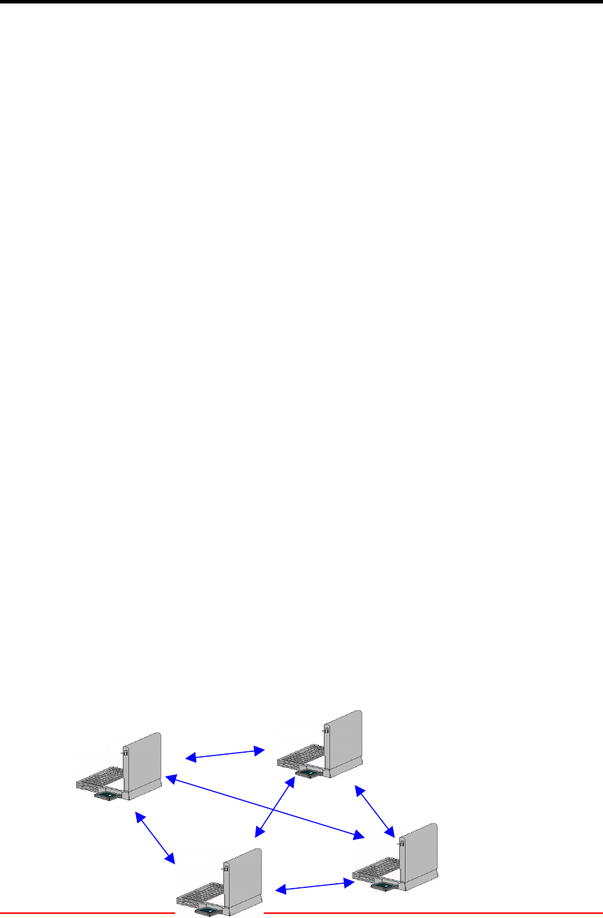
lAd Hoc Mode
Ad hoc mode (also called peer-to-peer mode or an Independent Basic
Service Set, or IBSS) is simply a set of 802.11 wireless stations that
communicate directly with one another without using an access point or any
connection to a wired network. This mode is useful for quickly and easily
setting up a wireless network anywhere that a wireless infrastructure does not
exist or is not required for services, such as a hotel room, convention center,
or airport, or where access to the wired network is barred (such as for
consultants at a client site).
Independent Basic
Service Set (IBSS)
!AcroLAN Card User’s Guide Version 20002.5
Copyright© Acrowave Systems 2000 DOC – xxx - yyy
Page 6 of 38
Figure 1. Ad Hoc Mode
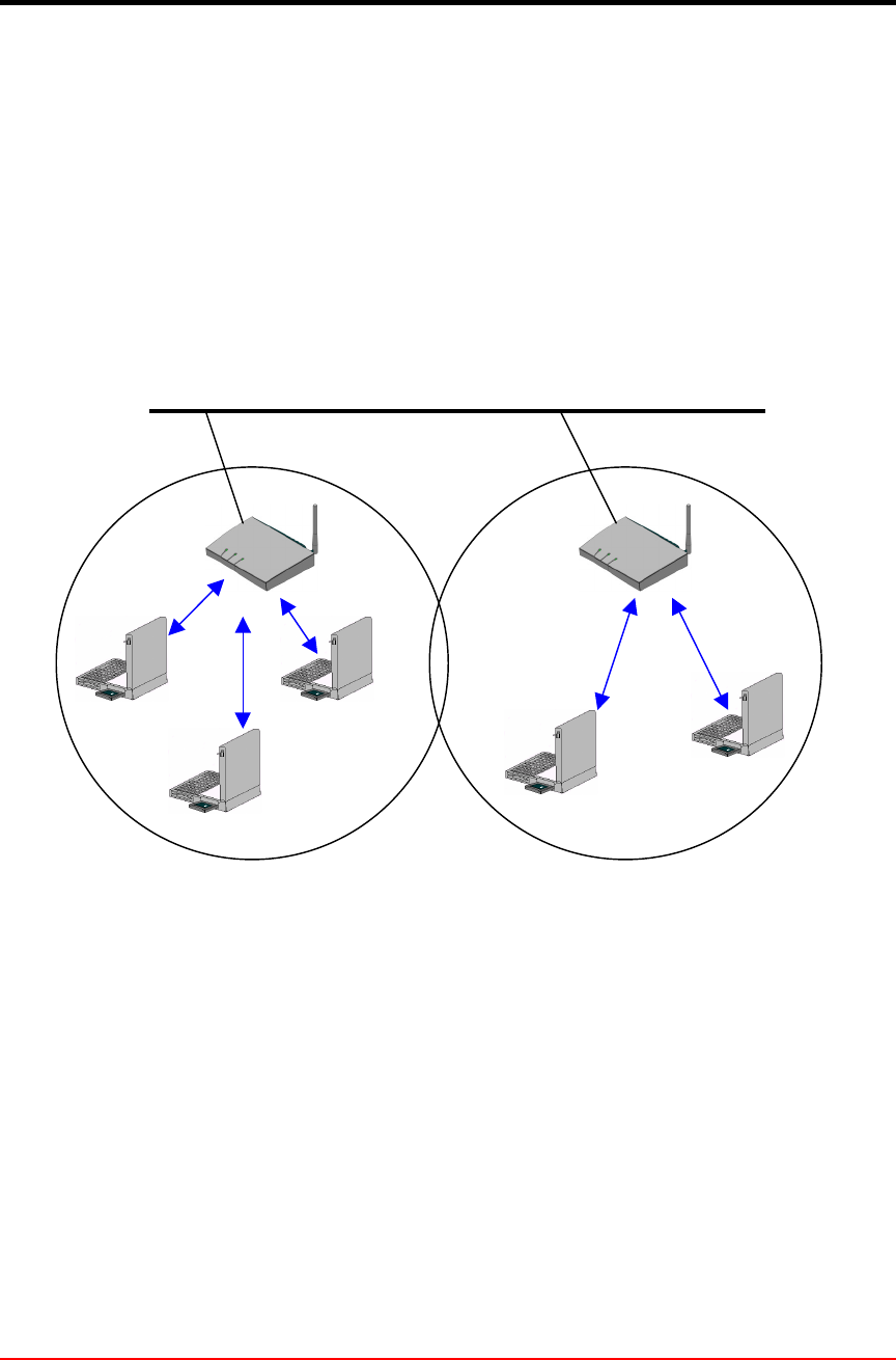
lInfrastructure Mode
In infrastructure mode, the wireless network consists of at least one access
point connected to the wired network infrastructure and a set of wireless end
stations. This configuration is called a Basic Service Set (BSS). An Extended
Service Set (ESS) is a set of two or more BSSs forming a single sub-network.
Since most corporate WLANs require access to the wired LAN for services
(file servers, printers, Inter-net links) they will operate in infrastructure mode.
Figure 2. Infrastructure Mode
ƒ
ƒƒ
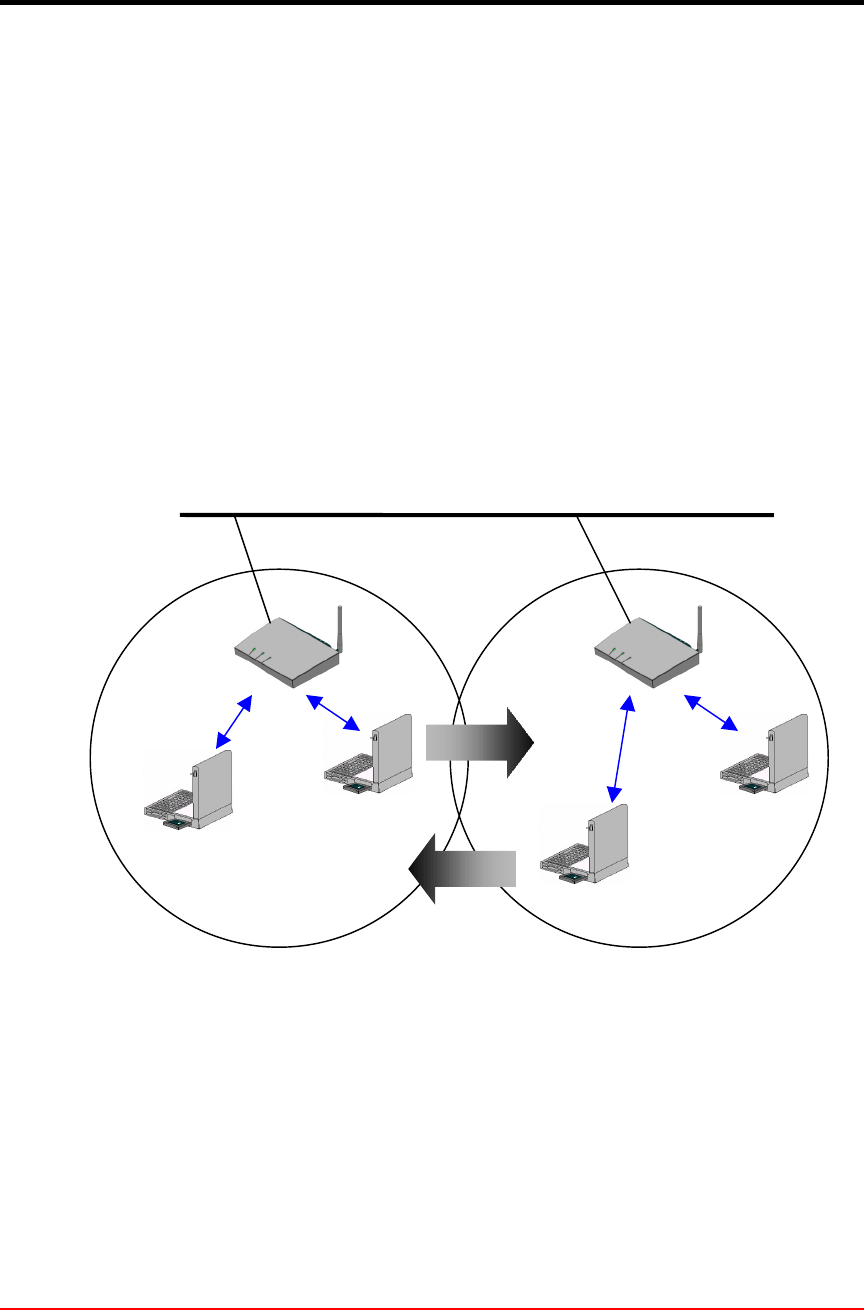
ƒRoaming
Wireless communication is limited by how far signals carry for given power output.
WLANs use cells, called microcells, similar to the cellular telephone system to extend
the range of wireless connectivity. At any point in time, a mobile PC equipped with a
WLAN adapter is associated with a single access point and its microcell, or area of
coverage. Individual microcells overlap to allow continuous communication within wired
network. They handle low power signals and “hand off” users as they roam through a
given geographic area.
The 802.11 MAC layer is responsible for how a client associates with an access point.
When an 802.11 client enters the range of one or more APs, it chooses an access point
to associate with (also called joining a Basic Service Set), based on signal strength and
Distribution System (DS)
Service Set (SS) – Multiple
le Cells
Access Point (AP)
Ethernet (802.3)
!AcroLAN Card User’s Guide Version 20002.5
Copyright© Acrowave Systems 2000 DOC – xxx - yyy
Page 7 of 38
observed packet error rates. Once accepted by the access point, the client tunes to the
radio channel to which the access point is set. Periodically it surveys all 802.11 channels
in order to assess whether a different access point would provide it with better
performance characteristics. If it determines that this is the case, it reassociates with the
new access point, tuning to the radio channel to which that access point is set.
Reassociation usually occurs because the wireless station has physically moved away
from the original access point, causing the signal to weaken. In other cases,
Reassociation occurs due to a change in radio characteristics in the building, or due
simply to high network traffic on the original access point. In the latter case this function
is known as “load balancing,” since its primary function is to distribute the total WLAN
load most efficiently across the available wireless infrastructure. This process of
dynamically associating and reassociating with APs allows network managers to set up
WLANs with very broad coverage by creating a series of overlapping 802.11b cells
throughout a building or across a campus. To be successful, the IT manager ideally will
employ “channel reuse,” taking care to set up each access point on an 802.11 DSSS
channel that does not overlap with a channel used by a neighboring access point.
Figure
3.
Roam
ing
Backbone Network
Access Point (AP)
Inter-Cell Roaming

!AcroLAN Card User’s Guide Version 20002.5
Copyright© Acrowave Systems 2000 DOC – xxx - yyy
Page 8 of 38
ƒ
ƒƒ
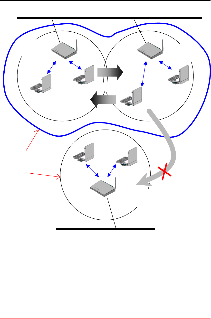
ƒBSS, ESS and SS ID
The basic service set (BSS) is the basic building block of WLAN network. Minimum
WLAN BSS may be consist of only two stations. Using access point (AP) and network
distribution systems (DS), WLAN service set can be extended arbitrary size – extended
service set (ESS). Each service set has its network ID (SSID). All the service sets within
an ESS network can have same service ID so that the ESS can support inter-cell
ROAMING.
!AcroLAN Card User’s Guide Version 20002.5
Copyright© Acrowave Systems 2000 DOC – xxx - yyy
Page 9 of 38
Figure 4. SSID and Roaming
Backbone Network
AP #`2 SS ID
= Acrowave
ROAMING
AP #`1 SS ID
= Acrowave
AP #`3 SS ID
=Acro
ESS
BSS
Backbone Network
Re-Configuration
Required

!AcroLAN Card User’s Guide Version 20002.5
Copyright© Acrowave Systems 2000 DOC – xxx - yyy
Page 10 of 38
Chapter 2 Before You Start AcroLAN
To use the AcroLAN adapter with a computing device (desktop personal computer,
notebook, laptop computer, portable or hand-held device), the device must be equipped
with an internal or external PC Card Type II or Type III slot. All drivers and supporting
software (card and socket services) for the client adapter slot must be loaded and
configured.
Ask your system administrator for the following information, which you may need to
provide during driver installation:
• Your Wireless Client Name
• Your Wireless SSID
• Your computer's unique client name and workgroup name
• For Windows NT, a free interrupt and I/O address.
• For your network account, your user name and password
• If you’re not using a DHCP server, your IP address, gateway address, and subnet
mask
After unpacking the card, make sure the following items are present and in good
condition:
• Acrowave AcroLAN AWL-1100 Series PC Card Adapter
• AWL-1100 Series install software and documentation CD for Windows
If any item is damaged or missing, contact your PC Card adapter supplier. Save all the
shipping and the packing material to repack the unit should service be required.
Caution
Before you start, close all working windows and backup important data.

!AcroLAN Card User’s Guide Version 20002.5
Copyright© Acrowave Systems 2000 DOC – xxx - yyy
Page 11 of 38
Chapter 3 Installing the PC/PCI Card Adapter on a Windows OS
This section provides instructions for installing a PC/PCI adapter on a computer using
one of the Windows operating systems.
Whatever operating systems(Windows 95/98/ME/2000/XP) you use the installation
procedures are all same. But, PCI card does not support for Windows XP.
Caution
The following procedures and physical connections apply generally to normal
and conventional client adapter slots. In the cases of custom or non-conventional
equipment, be alert to possible differences in client adapter slot configurations.
3.1 Installing PC Card Adapter
Before you begin, examine the client adapter. One end is a dual-row, 68-pin client
adapter connector. This side will be inserted into the client adapter slot with the logo on
the client adapter facing up. The card is keyed so it can be inserted only one way into
the slot.
The client adapter can be connected to a client adapter Type II slot. This includes slots
that support both Type II and Type III cards.
Caution
Do not force the client adapter into the slot. Forcing it will damage both the
client adapter and the slot. If the client adapter does not go in easily, remove the card
and reinsert it.
!AcroLAN Card User’s Guide Version 20002.5
Copyright© Acrowave Systems 2000 DOC – xxx - yyy
Page 12 of 38
3.1.1 Installing the PC Card Driver for Windows Operating Systems
×
××
×Windows95, 98, 2000, ME, XP
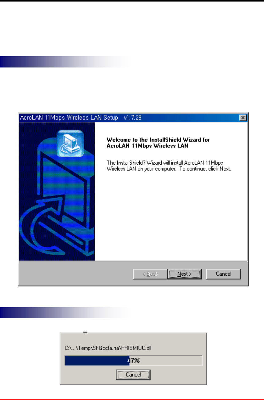
If the operating system on your computer is Windows, follow these steps.
If you insert the AcroLAN software and
documentation CD for Windows, the Windows automatically runs AcroLAN setup
program and a dialog box appears.
( Some CDs may not run automatically, in this case execute “Setpu.exe” file located at
the Card setup directory of CD.)
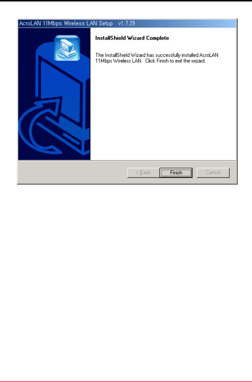
It takes a few seconds for copying the
utility files and then click on Finish to complete the installation.
STEP 1
STEP 2
!AcroLAN Card User’s Guide Version 20002.5
Copyright© Acrowave Systems 2000 DOC – xxx - yyy
Page 13 of 38
!AcroLAN Card User’s Guide Version 20002.5
Copyright© Acrowave Systems 2000 DOC – xxx - yyy
Page 14 of 38
Chapter 4 Connecting the AcroLAN Card to your computer
Caution
The following procedures and physical connections apply generally to normal
and conventional client adapter slots. In the cases of custom or non-conventional
equipment, be alert to possible differences in client adapter slot configurations.
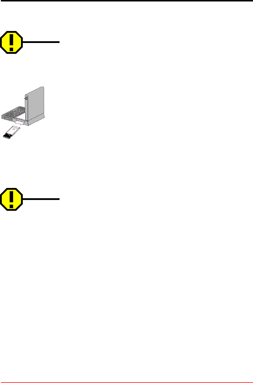
4.1 Installing AcroLAN PCMCIA Card
Before you begin, examine the card. One end is a dual-row, 68-pin client adapter
connector. This side will be inserted into the client adapter slot with card’s logo facing
up. The card is keyed so it can be inserted only one way into the slot.
The client adapter can be connected to a client adapter Type II slot. This includes slots
that support both Type II and Type III cards.
Caution
Do not force the card into the slot. Forcing it will damage both the client adapter
and the slot. If the client adapter does not go in easily, remove the card and reinsert it.
4.2 Installing AcroLAN PCI Card
This section describes the procedures for installing the client adapter.
Before You Start
For the client adapter to be used with a computing device, the device must be equipped
with a PCI or ISA expansion slot. Check the documentation that came with your
computer for details on the differences between PCI and ISA expansion slots.
Ask your system administrator for the following information, which you may need to
provide during driver installation:
• Your Wireless Client Name
• Your Wireless SSID
• Your computer's unique client name and workgroup name
• For your network account, your user name and password
• If you’re not using a DHCP server, your IP address, gateway address, and subnet
mask
After unpacking the client adapter, make sure the following items are present and in

!AcroLAN Card User’s Guide Version 20002.5
Copyright© Acrowave Systems 2000 DOC – xxx - yyy
Page 15 of 38
good condition:
• AcroLAN AWL-1100P Series PCI Client Adapter
• Standard 2 dBi dipole antenna
• AWL-1100P Series software and documentation CD for Windows 95/98 Windows ME,
Windows 2000 Installing the PCI Client Adapter
If any item is damaged or missing, contact your client adapter supplier. Save all shipping
and packing material in order to repack the unit should service be required.
This section provides instructions for installing a client adapter on a computer using one
of the Windows operating systems.
Before you begin, examine the client adapter. The antenna connector and Status and
Activity LEDs will face out of your computer, and will be visible when you put the cover
back on. The bottom edge of the card is the connector you will insert into an empty
expansion slot in your computer.
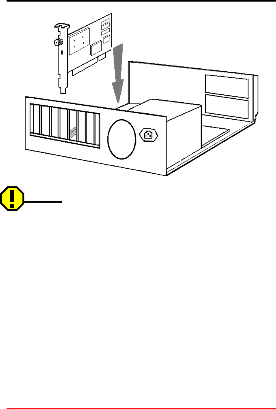
4.2.1 Installing PCI Card Adapter
1. Turn off the computer and all its components.
2. Remove the computer cover.
3. Remove the screw from the top of the CPU back panel above an empty expansion
slot. This screw is used to hold the metal bracket on the back panel.
4. Tilt the client adapter to allow the antenna connector and LED lights to slip through
the opening in the CPU back panel.
5. Press the client adapter into the empty slot until its connector is firmly seated.
!AcroLAN Card User’s Guide Version 20002.5
Copyright© Acrowave Systems 2000 DOC – xxx - yyy
Page 16 of 38
Caution
Do not force the client adapter into the slot. Forcing it will damage both the card
and the slot. If the card does not go in easily, remove the card and reinsert it.
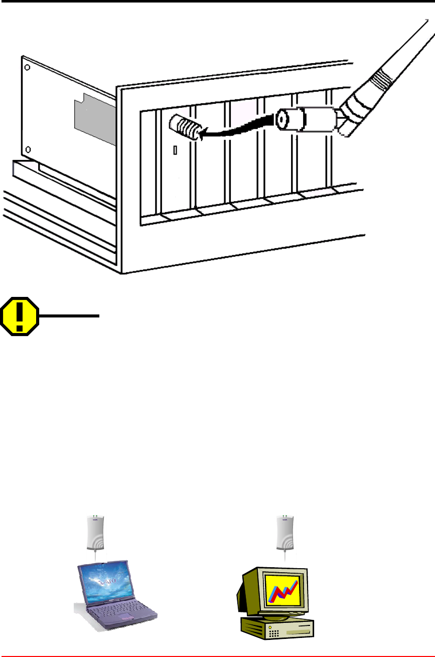
6. Reinstall the screw to the top of the CPU back panel.
7. The client adapter comes with one 2dBi dipole antenna. With the unit powered off,
attach the antenna to the antenna connector on the client adapter.
!AcroLAN Card User’s Guide Version 20002.5
Copyright© Acrowave Systems 2000 DOC – xxx - yyy
Page 17 of 38
Caution
Do not over-tighten the antenna connector; finger-tight is sufficient. Position the
antenna vertically for best omni-directional signal reception.
4.3 Installing AcroLAN USB Card
AWL-1100U is Wireless LAN Adapter and it provide USB1.1 host interface. USB can
use both notebook PC and desktop PC. Operation and installation method is same
with PC card.
To install AcroLAN USB Card, first connect one end of the USB cable to the card. Then,

!AcroLAN Card User’s Guide Version 20002.5
Copyright© Acrowave Systems 2000 DOC – xxx - yyy
Page 18 of 38
connect the other end of the USB cable to the USB port on your computer. Since the
card gets its power from the PC’s USB port, there is no external power adapter. The
Power LED should light up green when the Card is attached and the PC is on.
4.4 Installing AcroLAN Mini-PCI Card
AWL-1100M is Mini PCI type card and it can use at notebook PC. Antenna is located at
the side of monitor and it can improve link quality.It is very convenient to use because
the card is installed inside PC. It satisfy IEEE802.11b standard and support maximum
11Mbps data rate. It support also Ad-Hoc(Peer to Peer) and Infra structure mode.
Installation procedure of Mini PCI card is as below.
Install driver program first before insert card. Turn off PC power and insert card to PC.
Turn on PC power then it will automatically run installation program.
Caution
Please check the availability of your PC has Mini PCI slot before you purchase Mini PCI
card. Most of the case Mini PCI will be installed at manufacturing status.

!AcroLAN Card User’s Guide Version 20002.5
Copyright© Acrowave Systems 2000 DOC – xxx - yyy
Page 19 of 38
Chapter 5 Configuring the AcroLAN Card
If you have connected Wireless LAN card successfully, illuminating LED and Sound
confirms the detection of your card. Also you will see its icon on the right bottom of your
screen.
If you install Acrowave’s wireless LAN card for the first time all the setup process runs
automatically. If you reinstall, the install program asks next two files folder position and
you should select same as the below:
lLocation designation of inf file
Windows98, ME(filename : AcrowavePRISMNIC.inf)
C: \WINDOW\inf
Windows 95, 2000, XP(filename : PRISMNIC.inf)
C: \WINDOWS\inf
lLocation designation of driver file
Windows 95, 98, ME (filename : PRISMNDS.sys)
C: \WINDOWS\SYSTEM
Windows 2000, XP (filename : PRISMNDS.sys)
C: \WINDOWS\SYSTEM\Drivers
And then the install program asks whether you want to reboot your computer. At this
time you should select No in order to complete the installation correctly.
Left-click My Computer icon on your desktop and select Properties. Open Device
Manager In the Hardware Tab. If you find yellow (?) sign on the adaptor, it shows the
installation is not successful. Select the adaptor and click on Remove. Restart your
computer after uninstalling the driver to make the change effective.
5.1 Installing Network Protocols
Protocols are necessary for computers to be recognized on your network. Windows
2000 and XP users need to check their Windows User Guides for protocol installation.
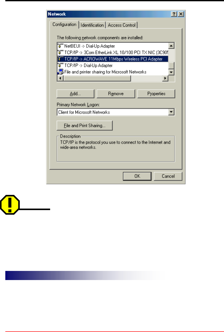
From the Start Menu, select Settings and bring up the Control Panel. From the Control
Panel, double-click on the Network icon. The Network box appears and you see three
main tabs; Configuration, Identification, Access control.
Select Wireless LAN Card on the configuration tab and then click the Add button.
Highlight Protocol, and click the Add button.
Select Microsoft from the list of “Manufacturers” and TCP/IP from the list of “Network
Protocols” Click the OK button to close the Network window. Windows may start
copying some files and ask you for your Windows installation files at this time. After the
files are copied Windows may ask you to restart. Click Yes to restart and complete the
installation process.
!AcroLAN Card User’s Guide Version 20002.5
Copyright© Acrowave Systems 2000 DOC – xxx - yyy
Page 20 of 38
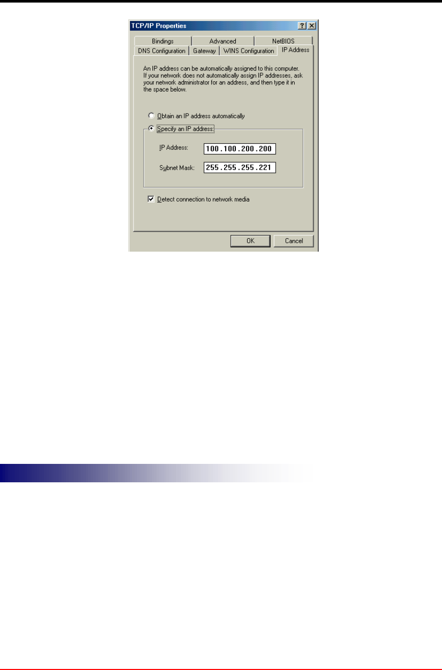
Caution
This Process could cause serious problem on your network if you edit wrong data. So, if you do
not know how to configure your network option, ask for help your network administrator.
Click on the TCP/IP option for setting the IP address for your computer. You can select either
Static or DHCP setting. If you use static IP address then enter the IP value assigned for you, and
Subnet masking, DNS, Domain/Workgroup name, Gateway address value.
IP Address
IP AddressIP Address
IP Address
!AcroLAN Card User’s Guide Version 20002.5
Copyright© Acrowave Systems 2000 DOC – xxx - yyy
Page 21 of 38
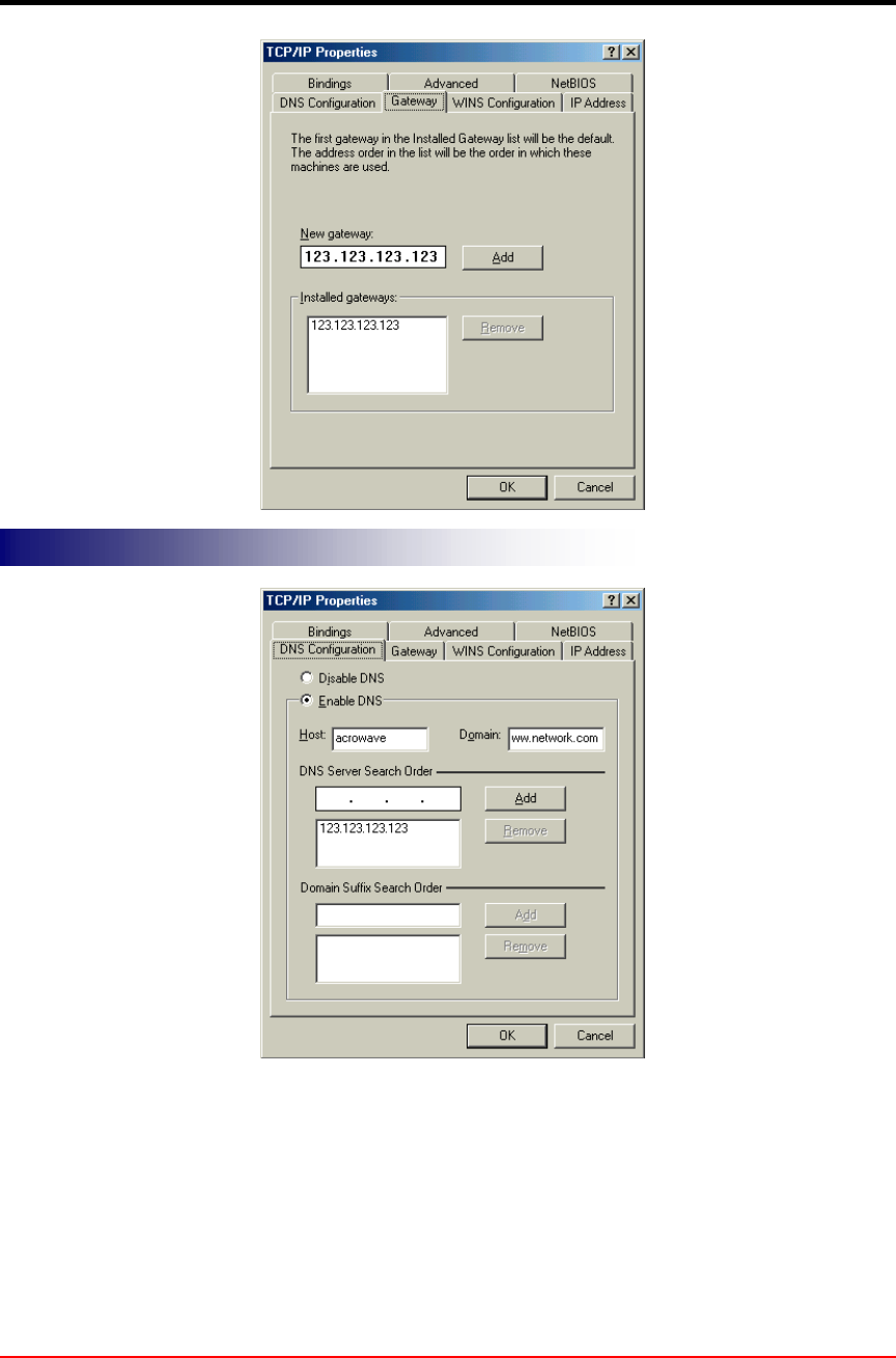
Gateway Address
Gateway AddressGateway Address
Gateway Address
!AcroLAN Card User’s Guide Version 20002.5
Copyright© Acrowave Systems 2000 DOC – xxx - yyy
Page 22 of 38
After setting these parameters appropriately, click on OK to return Network Component
Type and you can select the File and Printer Sharing options as well as the Access to
your computer by other users connected to that network by setting the computer
sharing options.
Click on OK.
DNS
DNSDNS
DNS

!AcroLAN Card User’s Guide Version 20002.5
Copyright© Acrowave Systems 2000 DOC – xxx - yyy
Page 23 of 38
Screen message “Do you want to restart your computer” will pop up. Select Yes. It will
shut down your computer and will restart.
!AcroLAN Card User’s Guide Version 20002.5
Copyright© Acrowave Systems 2000 DOC – xxx - yyy
Page 24 of 38
5.2 Uninstalling AcroLAN Card Driver
If you want to uninstall the PC card, click on the control panel. Select the Add/Remove
Programs. Click on the Acrowave 11Mbps Wireless LAN and click on Add/Remove
button. Uninstall Shield removes the software successfully.
And then, click System icon in the control panel and removes the ACROWAVE 11Mbps
Wireless PC Card adapter under the Network adapters.
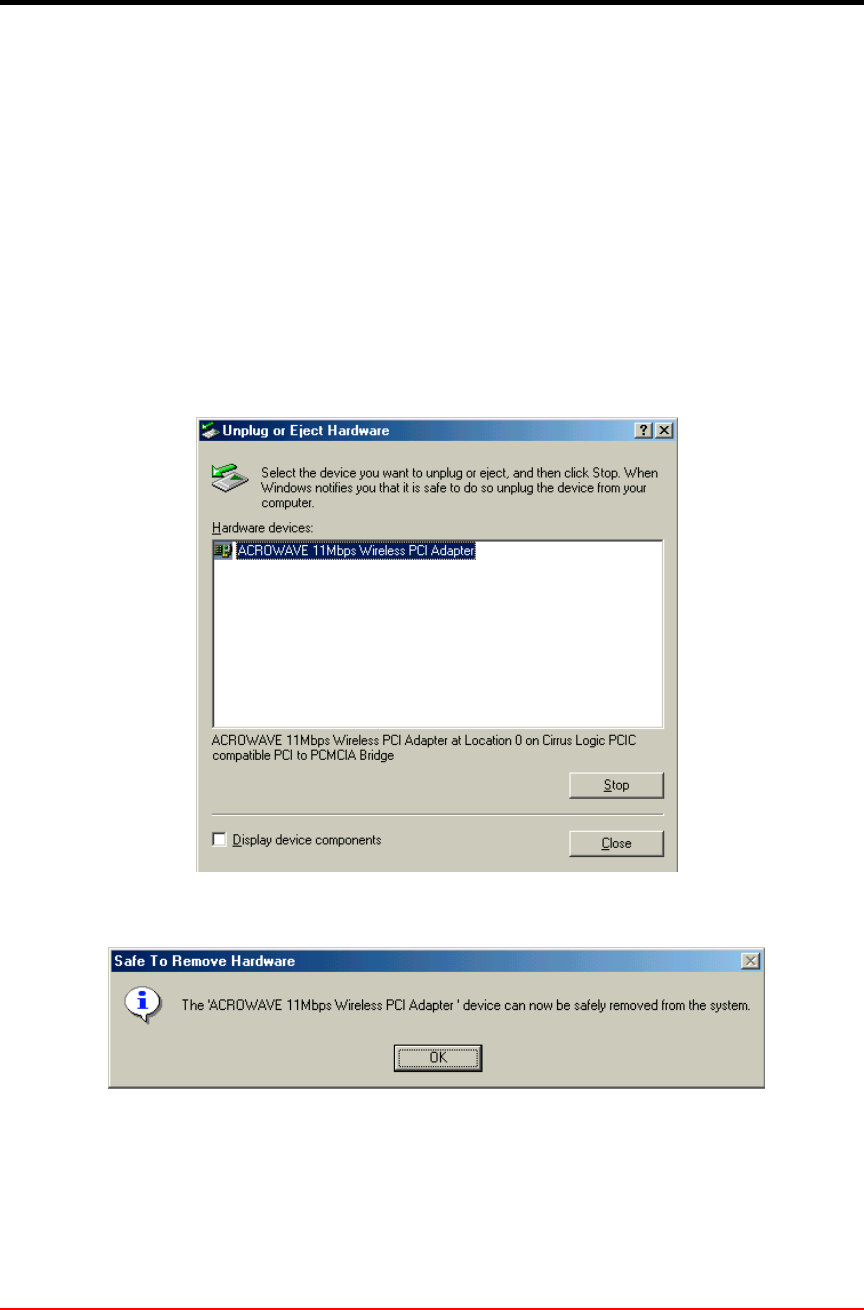
5.3 Remove PC Card from PC card socket
5.3.1 Remove PCMCIA AcroLAN Card /PCI AcroLAN Card
If you want to extract PC card from PC card socket, click on PC card information icon.
Click on Socket Status window and select ACROWAVE 11Mbps Wireless PC cars
adapter and click on Stop button.
After a few second, screen message “You can remove this device safely” will pop up.
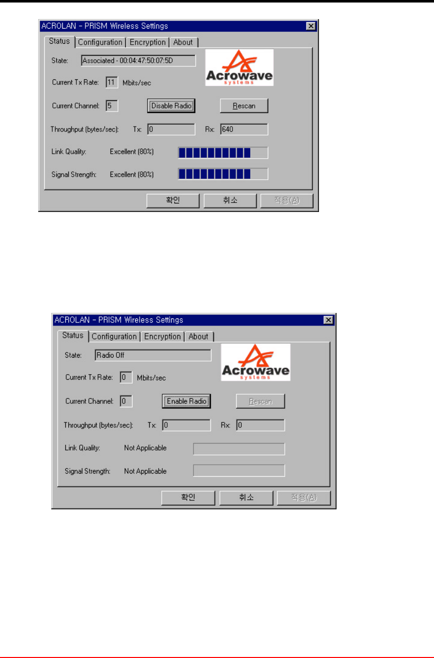
5.3.2 Remove USB AcroLAN Card
PC may shut down or malfunction if you pull out USB connector from PC without proper
procedure. It will be okay if you follow as below.
!AcroLAN Card User’s Guide Version 20002.5
Copyright© Acrowave Systems 2000 DOC – xxx - yyy
Page 25 of 38
Above utility window will be pop up when you click PC monitor shape green icon.
Select “ Radio Disable”.
Then PC icon will be display with X and it means Wireless LAN operation is stoped.
After PC monitor shape green icon go out of sight, Pull out USB connector from PC.
If you want to use again then connect USB port to PC and select “Enable Radio” at utility
window.
5.3.3 Remove Mini-PCI AcroLAN Card
Be sure to turn off PC power before remove.

!AcroLAN Card User’s Guide Version 20002.5
Copyright© Acrowave Systems 2000 DOC – xxx - yyy
Page 26 of 38
!AcroLAN Card User’s Guide Version 20002.5
Copyright© Acrowave Systems 2000 DOC – xxx - yyy
Page 27 of 38
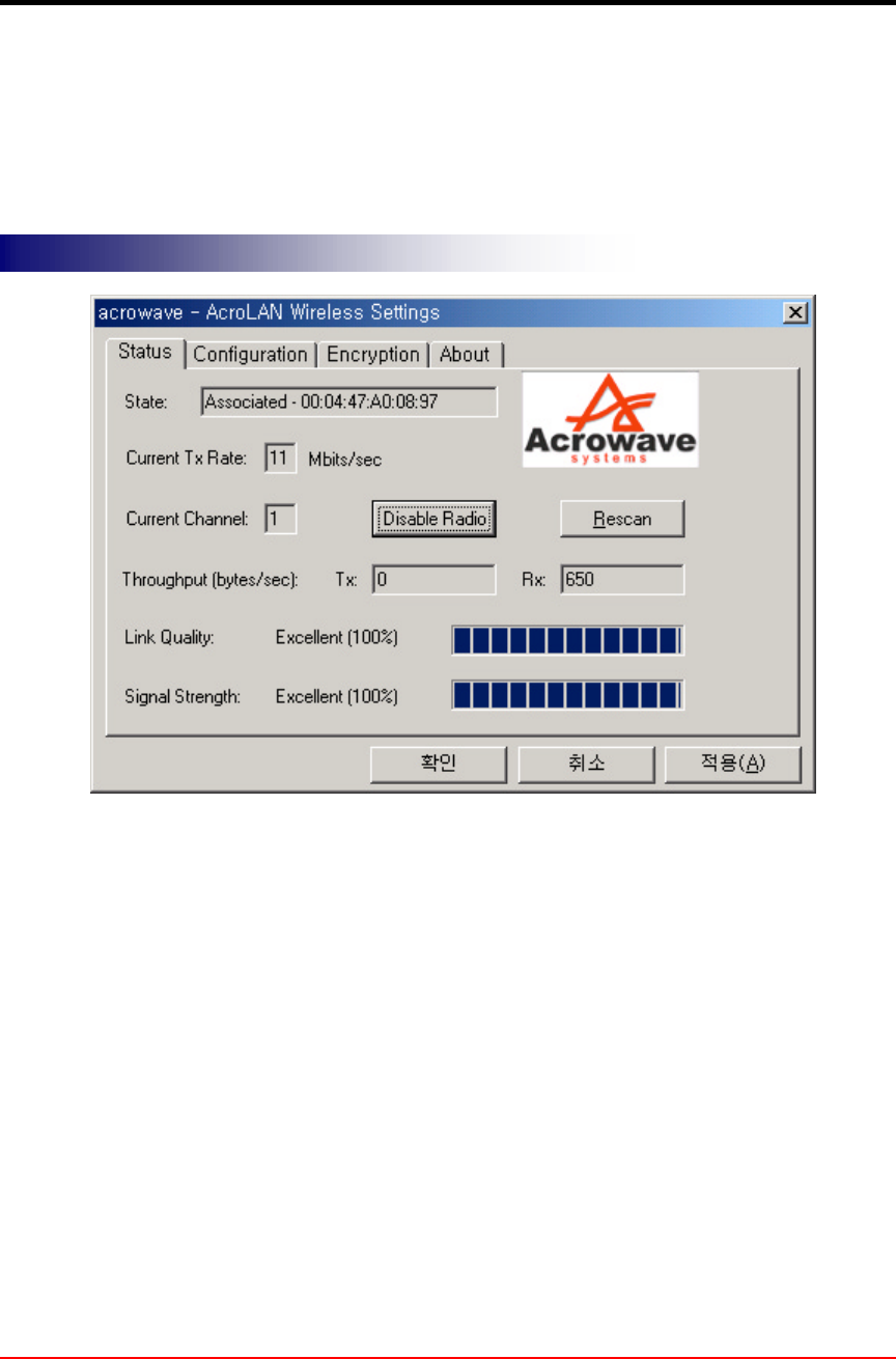
5.4 AcroLAN Configuration Utility
Acrowave install shied program installs wireless LAN driver program and Configuration
Utility program. You can see the icon at the right bottom of your screen. Click on that
icon will show you the screen as show below.
Status shows wireless LAN card’s MAC address information.
Current Tx Rate shows transmit data rate.
Current Channel shows selected channel number.
Channel number is the channel available for the communications between the client
and AP or between the clients only. In case of the Infrastructure Network Mode, the
channel number scanned automatically, while in case of the Ad-hoc Network Mode, the
channel number is set by the client and can be changed by the client user.
If you click on Rescan button, LAN card program searches other new channel that
currently used one.
Throughput (Byte/sec) shows transmit/receive data rate.
Link Quality shows measured radio link quality. If the link quality is bad, your computer
may not communicate with other client computers. Otherwise (; fair, good…), there is
no problem to communicate with other clients.
Signal Strength is similar to Link Quality information but slightly differ from it. But
Wireless Link Status
Wireless Link StatusWireless Link Status
Wireless Link Status
!AcroLAN Card User’s Guide Version 20002.5
Copyright© Acrowave Systems 2000 DOC – xxx - yyy
Page 28 of 38
usually, the quality level moves simultaneous with the Link Quality level.
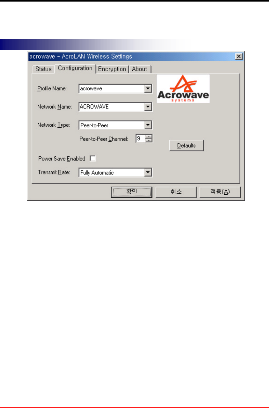
Network Type : You can select wireless LAN network mode – Infrastructure(Access
Point) or Ad-hoc(Peer-to-Peer) mode
Infrastructure Mode
This mode is used to set up a connection to a wired Ethernet network. This mode
requires an ACROLAN Access Point to gain access to the wired network.
Ad Hoc Mode
This mode is used to set up a small, temporary network between two or more
computers. For example, you might set up an ad hoc network between computers in a
conference room so users can share information in a meeting.
Network Name(SSID) :The Service Set Identifier (SSID) controls access to a given wireless
network. This value MUST match the SSID of any and all AcroLAN Access Points that you want
to communicate with. If the value does not match, access to the system is not granted. The SSID
can be up to 32 case-sensitive characters.
Transmit Rate: The transmission rate at which the data packets are transmitted by the
client or AP. You can set this value to 1~2Mbps, 5.5Mbps, 11Mbps or Fully Automatic.
Power Save Enabled : Power Saving Mode. Currently, the Power Save mode does not
supported.
After changing the setting in the Configuration change dialog box, click on Apply
Changes button. It takes a few seconds to set changes that you made.
Network Configuration
Network ConfigurationNetwork Configuration
Network Configuration
!AcroLAN Card User’s Guide Version 20002.5
Copyright© Acrowave Systems 2000 DOC – xxx - yyy
Page 29 of 38
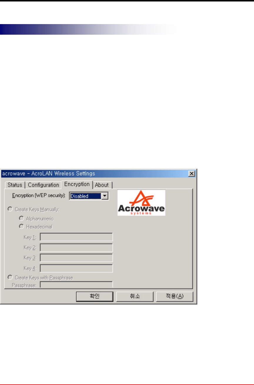
In order to do secure communication over the wireless LAN network, wireless LAN
module provides encryption function - WEP. There are two ways to generate WEP key.
This key is an important in protecting the illegal access to the wireless networks.
If you want to use WEP function, the AP also set the same WEP key value with you.
Andalltheuserswhowanttocommunicatewithyoumustusesamekeywitheach
other.
You can select WEP key Disable in Configuration dialog box, the communication
between clients and AP does not secure.
Encryption
EncryptionEncryption
Encryption - WEP
- WEP - WEP
- WEP

!AcroLAN Card User’s Guide Version 20002.5
Copyright© Acrowave Systems 2000 DOC – xxx - yyy
Page 30 of 38
There are two ways to generate the WEP key. One is by entering any text in the
Passphrase. And click on Generate button. It will generate four WEP keys; Key 1, Key 2,
Key 3, Key 4. You can select any key for the security. If you do not select any key, Key 1
is selected in default.
The other way is by entering Key value directly from the keyboard. Select the Key
number and use that Key for accessing the AP. If the Key is not entered correctly, a
client cannot access any other client or AP. This Key value protects the illegal access to
the wireless network resources. As the wireless channel is more prone to the illegal
access, WEP provides the users safe wireless LAN network access.
Caution
If you use WEP function, your network throughput degrade

!AcroLAN Card User’s Guide Version 20002.5
Copyright© Acrowave Systems 2000 DOC – xxx - yyy
Page 31 of 38
Chapter 6 Troubleshooting
In this chapter, we have listed various problems that you may encounter during the
installation and have also listed possible solutions.
£Change your location or the location of the antenna by a few feet and try again.
£Make sure the client adapter card is securely inserted in the expansion slot.
£Make sure the antenna is securely attached.
£Make sure that your computers SSID have the same one with other clients.
( Set all clients to the same channel number in case of Ad-hoc network mode.
( Make sure that you are with in the range of an AP. If your computer cannot be
associated with any AP, it cannot communicate with other clients.
( Make sure the antenna is securely attached.
!
(You
can communicate with other clients but air link quality is not good so data
transferred slowly. In this case, you may move your computer or wireless LAN card
antenna to higher position than current state or closer position with AP.
!
(Make
sure that the PC card is started as automatic in the device applet of the Control
panel.
£Double click on the PC card icon in the Control panel. Click on AcroLAN adapter
and then click on the properties button. It should say that the driver started
correctly.
£Make sure the drivers were installed correctly. If there is some warning or error,
uninstall drivers and software through Add/Remove Program, remove the Wireless
LAN card and reinstall the drivers following the manual.
£Make sure that the client computer is with in the range of an AP and uses same
SSID with you.
The system tray wireless monitor icon
The system tray wireless monitor icon The system tray wireless monitor icon
The system tray wireless monitor icon is always red
is always red is always red
is always red
The system tray wireless monitor icon
The system tray wireless monitor icon The system tray wireless monitor icon
The system tray wireless monitor icon is always yellow
is always yellow is always yellow
is always yellow
Cannot find wireless monitor icon
Cannot find wireless monitor icon Cannot find wireless monitor icon
Cannot find wireless monitor icon in the taskbar
in the taskbarin the taskbar
in the taskbar
Cannot connect to some computers
Cannot connect to some computersCannot connect to some computers
Cannot connect to some computers

!AcroLAN Card User’s Guide Version 20002.5
Copyright© Acrowave Systems 2000 DOC – xxx - yyy
Page 32 of 38
£Make sure that your TCP/IP is set properly and correctly.

!AcroLAN Card User’s Guide Version 20002.5
Copyright© Acrowave Systems 2000 DOC – xxx - yyy
Page 33 of 38
Appendix
Appendix A Cell Planning (Radio Range)
This section provides general guidelines on factors that influence network performance
Cell Site Survey
Because of differences in component configuration, placement and physical
environment, every network application is a unique installation. Before installing the
system, users should perform a site survey to determine the optimum utilization of
networking components and to maximize range, coverage and network performance.
Here are some operating and environmental conditions you should consider:
•Data Rates
Radio signal sensitivity and range are inversely proportional to data bit rates. The
maximum radio range is achieved at the lowest workable data rate. There will be a
decrease in receiver threshold sensitivity as the radio data rate increases.
•Antenna Type and Placement(PCI card only)
Proper antenna configuration is a critical factor in maximizing radio range. As a general
guide, range increases in proportion to antenna height. For a detailed explanation of
antenna types and configurations along with guidelines on selecting antennas for
specific environments, see the documentation that comes with your antenna.
•Physical Environments
Clear or open areas provide better radio range than closed or filled areas. Also, the less
cluttered the work environment, the greater the range.
•Obstructions
A physical obstruction such as metal shelving or a steel pillar can hinder the
performance of the client adapter. Avoid locating the computing device in a location
where there is a metal barrier between the sending and receiving antennas.
•Building Materials
Radio penetration is greatly influenced by the building material used in construction. For
example, drywall construction allows greater range than concrete blocks. Metal or steel
construction is a barrier to radio signals.
Enhancing Coverage
The system architecture options of the wireless station and AcroLAN Access Points
provide for a variety of coverage alternatives and flexibility. The system can be designed
to provide a wide coverage area with minimal overlap or coverage with heavy overlap.
The latter improves system performance and protection against downtime in the event of
a component failure. By arranging the AcroLAN Access Points so the overlap in
coverage area is minimized, a large area can be covered with minimal system cost. The
total bandwidth available to each mobile station will depend on the amount of data each

!AcroLAN Card User’s Guide Version 20002.5
Copyright© Acrowave Systems 2000 DOC – xxx - yyy
Page 34 of 38
mobile station desires to transfer and the number of stations located in each cell.
Seamless roaming is supported as a mobile station moves in and out of range of each
AcroLAN Access Point, thereby maintaining a constant connection to the wired LAN.
Each device in the radio network must be configured with the same Service Set Identifier
(SSID) to provide the roaming capability. Multiple systems can operate in the same
vicinity. The architecture provides multiple channels, which can coexist in the same area
with virtually no interference to each other. In this mode, each system must be
configured with different Service Set Identifiers (SSID) and different channels, which
prevent clients from roaming to AcroLAN Access Points of a different wireless system.

!AcroLAN Card User’s Guide Version 20002.5
Copyright© Acrowave Systems 2000 DOC – xxx - yyy
Page 35 of 38
Appendix B Technical Specifications
Supported Operating Systems
Windows 95, Windows 98, Windows 2000, Windows ME, Windows XP
Radio Specifications
Item Specification Description
Radio Type
Direct Sequence
Spread-Spectrum
(DSSS)
2.4 GHz ISM Band
Operating Frequency 2400-2483.5 MHz
North American, ETSI, and
Japan channel coverage, factory
configurable
FCC ID FCC approval
Channeling 5 MHz increments Programmable for IEEE 802.11b
Type of Modulation
BPSK 1 Mbit/s
QPSK 2 Mbit/s
CCK 5.5 and 11 Mbits/s
Nominal 10 MHz BW
(-6 dB)
Receiver sensitivity
–87 dBm @ 1 Mbps
–85 dBm @ 2 Mbps
–84 dBm @ 5.5 Mbps
–81 dBm @ 11 Mbps

!AcroLAN Card User’s Guide Version 20002.5
Copyright© Acrowave Systems 2000 DOC – xxx - yyy
Page 36 of 38
Power Requirements
-PCCard
Specification Value
Operational Voltage 3.3V ± 0.25V
Receive Mode Current 250 mA (200 mA typically)
High Power Transmit Mode Current 400 mA (370 mA typically)
Sleep Mode Current 30 mA typically
- PCI Card
Specification Value
Operational Voltage 5.0V ± 0.25V
Receive Mode Current 250 mA (200 mA typically)
High Power Transmit Mode Current 470 mA (450 mA typically)
Sleep Mode Current 40 mA typically
-USBCard
Specification Value
Operational Voltage 5.0V ± 0.25V
Receive Mode Current 250 mA (200 mA typically)
High Power Transmit Mode Current 390 mA (370 mA typically)
Sleep Mode Current 15 mA typically
- Mini-PCI Card
Specification Value
Operational Voltage 3.3V± 0.25V
Receive Mode Current 240 mA (200 mA typically)
High Power Transmit Mode Current 390 mA (450 mA typically)
Sleep Mode Current 15 mA typically
Physical Specifications
PC Card
Item Description
Size 114 mm L x 54 mm W x 5 mm H
Enclosure PC Card Type II
Operating Temperature 0°C to 70°C minimum (32°F to 158°F)
Connectors 68-pin PCMCIA card
Status Indicators Green LEDs – link association/activity
PCI Card
Item Description

!AcroLAN Card User’s Guide Version 20002.5
Copyright© Acrowave Systems 2000 DOC – xxx - yyy
Page 37 of 38
Size 149 mm L x 121 mm W x 18 mm H
Operating Temperature 0°C to 70°C minimum (32°F to 158°F)
Connectors PCI Card edge
Status Indicators Green LEDs – link association/activity
USB Card
Item Description
Size 56 mm L x 121.8 mm W x 10.5 mm H
Operating Temperature 0°C to 50°C minimum
Connectors Mini USB Card wafer
Status Indicators Green LEDs – link association/activity
Mini-PCI Card
Item Description
Size 59.7 mm L x 59.95 mm W x 3mm H
Operating Temperature 0°C to 55°C minimum
Connectors Mini-PCI Card edge
Status Indicators None

!AcroLAN Card User’s Guide Version 20002.5
Copyright© Acrowave Systems 2000 DOC – xxx - yyy
Page 38 of 38
Appendix C Channel Allocation
The channel identifiers and the channel center frequencies of each 22-MHz-wide
channel are shown in the table below, as appropriate for the various areas or regulatory
agencies.
Regulatory Domains
Channel
Identifier
Center
Frequency North
America ETSI Spain France Korea /
Japan
1 2412MHz √
√√
√√
√√
√−−√
√√
√
2 2417MHz √
√√
√√
√√
√−−√
√√
√
3 2422MHz √
√√
√√
√√
√−−√
√√
√
4 2427MHz √
√√
√√
√√
√−−√
√√
√
5 2432MHz √
√√
√√
√√
√−−√
√√
√
6 2437MHz √
√√
√√
√√
√−−√
√√
√
7 2442MHz √
√√
√√
√√
√−−√
√√
√
8 2447MHz √
√√
√√
√√
√−−√
√√
√
9 2452MHz √
√√
√√
√√
√−−√
√√
√
10 2457MHz √
√√
√√
√√
√√
√√
√√
√√
√√
√√
√
11 2462MHz √
√√
√√
√√
√√
√√
√√
√√
√√
√√
√
12 2467MHz −√
√√
√−√
√√
√√
√√
√
13 2472MHz −√
√√
√−√
√√
√√
√√
√
14 2484MHz −−−−√
√√
√