Actia Nordic ACUII-06 ACUII-06 User Manual 6001 40023 acuii 06 nas 1 4
ACTIA Nordic AB ACUII-06 6001 40023 acuii 06 nas 1 4
UserManual.wiki
>
Actia Nordic
>
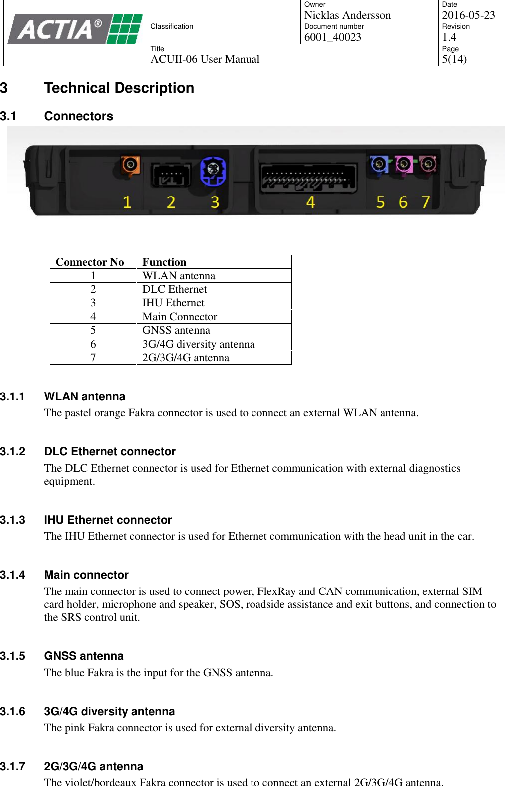
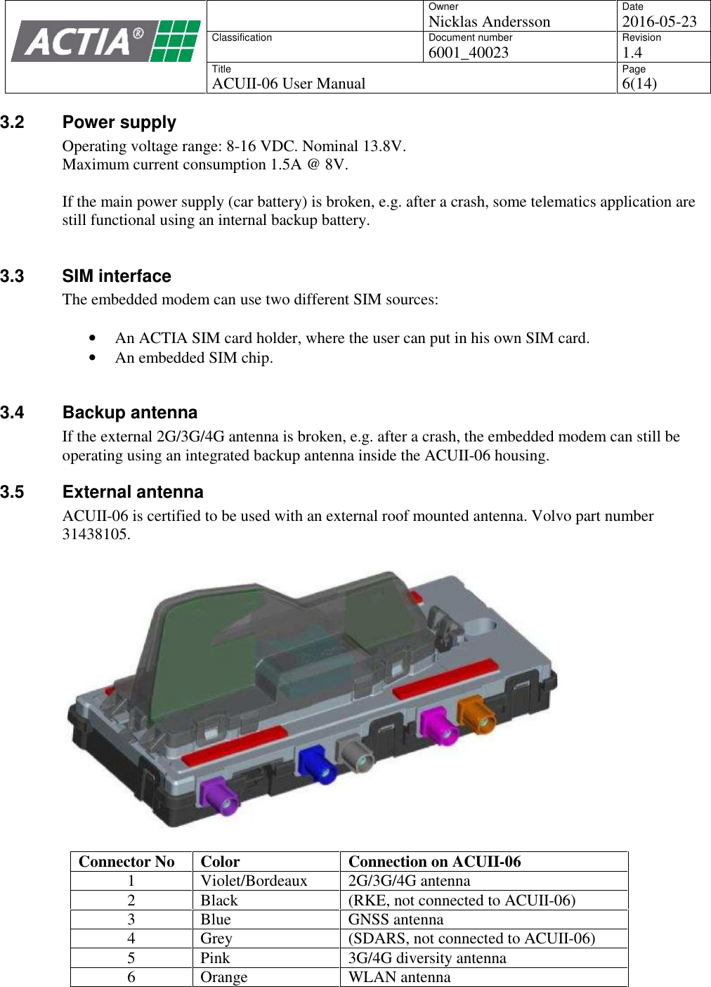
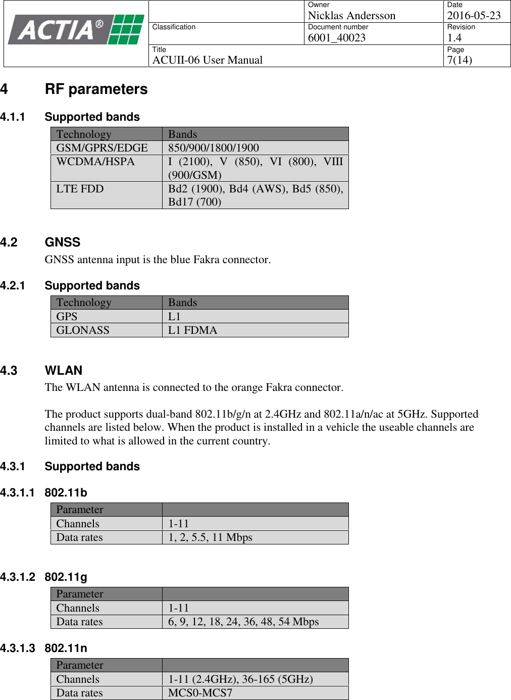
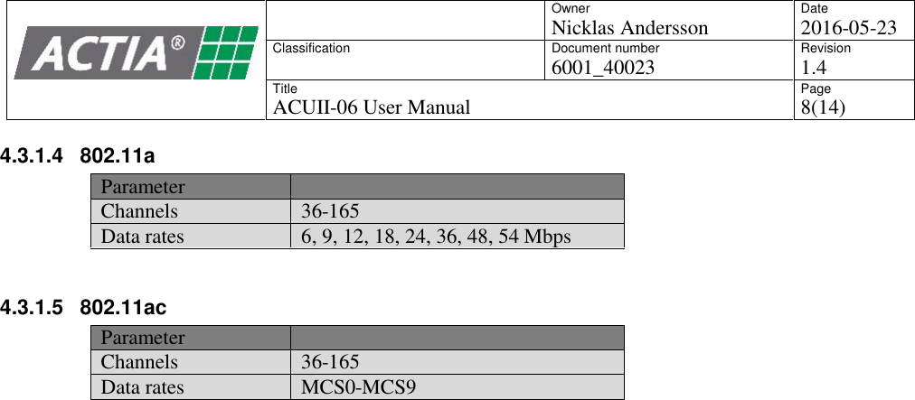
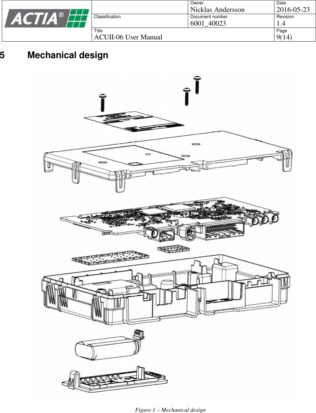
ACUII 06 User Manual
6001_40023_acuii-06 user manual (nas)_1.4
Navigation menu
Upload a User Manual
Namespaces
Wiki Guide
HTML
PDF
Info
Views
User Manual
Discussion / Help
Navigation