Actiontec Electronics 802RUN2 Wireless Dual-Band USB Module User Manual
Actiontec Electronics Inc Wireless Dual-Band USB Module
User Manual.pdf

W725D0 802.11ABGN 2T2R USB Module Page 1 of 12
Product Specification
Model Name: W725D0
Part No.: WW725D0566A20H
IEEE 802.11ABGN 2T2R USB Module
Version: 1.1
Date: June. 5. 2013

W725D0 802.11ABGN 2T2R USB Module Page 2 of 12
Release History
DATE REV Description of Change
2012/07/30
0.1 Preliminary specification release
2012/10/02
0.2 Add power consumption
2012/10/04
0.3 Update block diagram
2012/10/13
0.4 Update dimension and power consumption
2012/11/15
1.0 Change model name to W725D0, update RF Spec.
2013/5/7 1.0 Customized for Actiontec
2013/6/5 1.1 Delete dual MAC description and Modify FCC Label

W725D0 802.11ABGN 2T2R USB Module Page 3 of 12
W725D0
IEEE 802.11ABGN 2T2 USB Module
1 Product Features
Supports 2T2R 2.4/5GHz dual-band
Maximum PHY data rate up to 144.4 Mbps using 20MHz bandwidth, 300Mbps using
40MHz bandwidth
Short Guard Interval (400ns)
Sounding packet
Host interface complies with USB Specification Revision 2.0
Supports IEEE 802.11 e/ i/ h/ k
WAPI (Wireless Authentication Pivacy Infrastructure) cerified
Frame aggregation for increased MAC efficiency (A-MSDU, A-MPDU)
Low latency immediate High-Throughput Block Acknowledgement (HT-BA)
Long NAV for media reservation with CF-End for NAV release
PHY-level spoofing to enhance legacy compatibility
MIMO power saving mechanism
Channel management and co-existence
Supports Wake-On-WLAN via Magic Packet and Wake-up frame
Transmit Opportunity (TXOP) Short Inter-Frame Space (SIFS) bursting for higher
multimedia bandwidth
WiFi Direct supports wireless peer to peer applications.
W725D0 802.11ABGN 2T2R USB Module Page 4 of 12
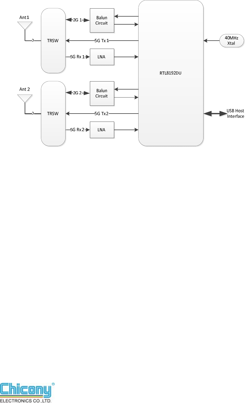
2 Block Diagram
W725D0 802.11ABGN 2T2R USB Module Page 5 of 12
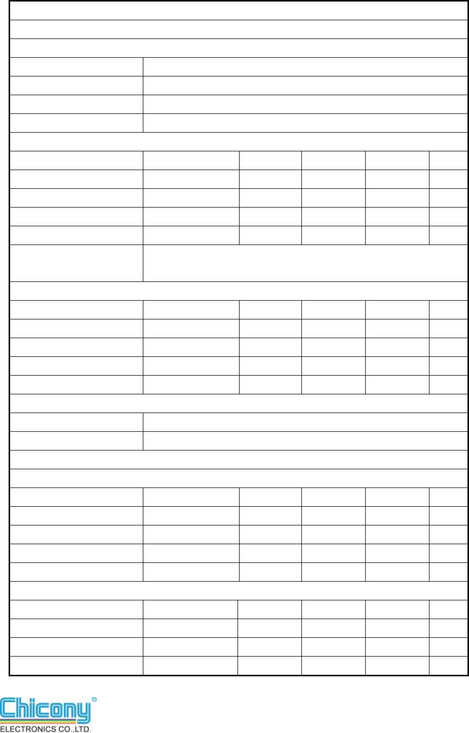
3 General Specification
Module Name
W725D0
Product Specification
WLAN StandardIEEE 802.11a/b/g/n
Host InterfaceUSB 2.0
Host Connector Options4 pins header type connector
Major ChipsetRealtek RTL8192DU
Dimensions (board size)
Minimum Typical Maximum Unit
Length 60.2 60.5 60.8 mm
Width 22.4 22.6 22.8 mm
Height 2.9 3.1 3.3 mm
Weight 6.8 7 7.2 g
Antenna Connector
Options
2 printed PCB antennas on board
Operating Condition
Minimum Typical Maximum Unit
VoltageDC 4.74 5 5.25 V
Temperature 0 70 °C
Storage temperature -20 70 °C
Humidity Non-Operating
10 80 %
Electrical Specification
Frequency Range2400 ~ 2483 MHz; 5150 ~ 5825 MHz
Band Width20MHz/ 40MHz Mixed mode
2.4GHz Band
Output power
Minimum Typical Maximum Unit
802.11b 15 17 19 dBm
802.11g 54Mbps 9 11 13 dBm
802.11n/ HT20 MCS7 7 9 11 dBm
802.11n/ HT40 MCS7 7 9 11 dBm
Receiver Sensitivity
Minimum Typical Maximum Unit
802.11b11Mbps -80 dBm
802.11g 54Mbps -65 dBm
802.11n/ HT20 MCS7 -64 dBm
W725D0 802.11ABGN 2T2R USB Module Page 6 of 12
802.11n/ HT40 MCS7 -61 dBm
5GHz Band
Output power
Minimum Typical Maximum Unit
802.11a 54Mbps 8 10 12 dBm
802.11n/ HT20 MCS7 Lower/ Middle Band
7 9 11 dBm
802.11n/ HT20 MCS7 Upper Band 5 7 9 dBm
802.11n/ HT40 MCS7 Lower/ Middle Band
7 9 11 dBm
802.11n/ HT40 MCS7 Upper Band 5 7 9 dBm
Receiver Sensitivit y
Minimum Typical Maximum Unit
802.11a 54Mbps -65 dBm
802.11n/ HT20 MCS7 -64 dBm
802.11n/ HT40 MCS7 -61 dBm
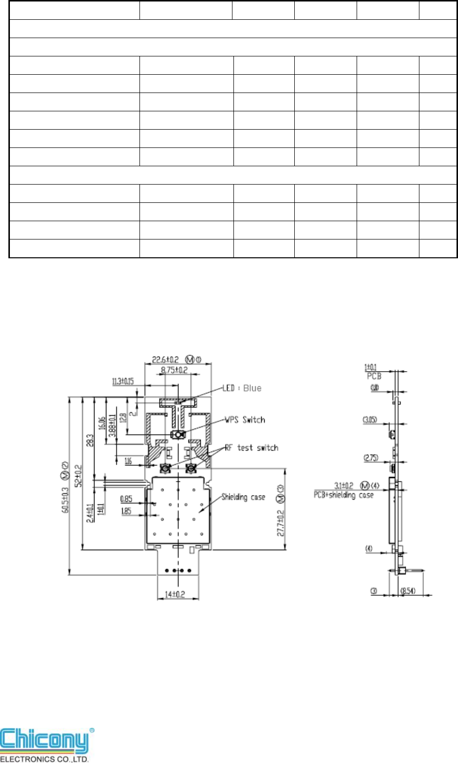
4 Mechanical Dimension
W725D0 802.11ABGN 2T2R USB Module Page 7 of 12
5 Power Consumption
Test condition
OS:Windows XP
Channel 6:2437MHz
Standard:IEEE802.11B,G.N
Input voltage for whole circuit:4.97V
TX uses continuous mode
Test tool
MP_Kit_RTL11n_DualMAC_9xD_USB_v019_20120307
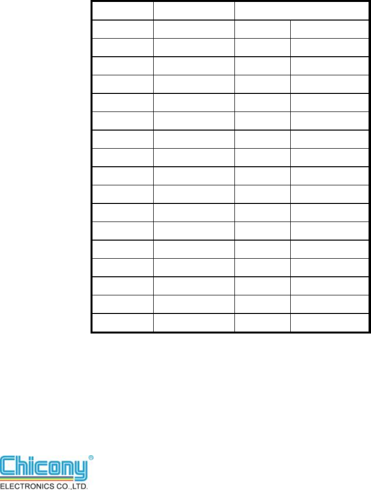
5.1 Test result:
Continuous TX/RX @ 2.4GHz
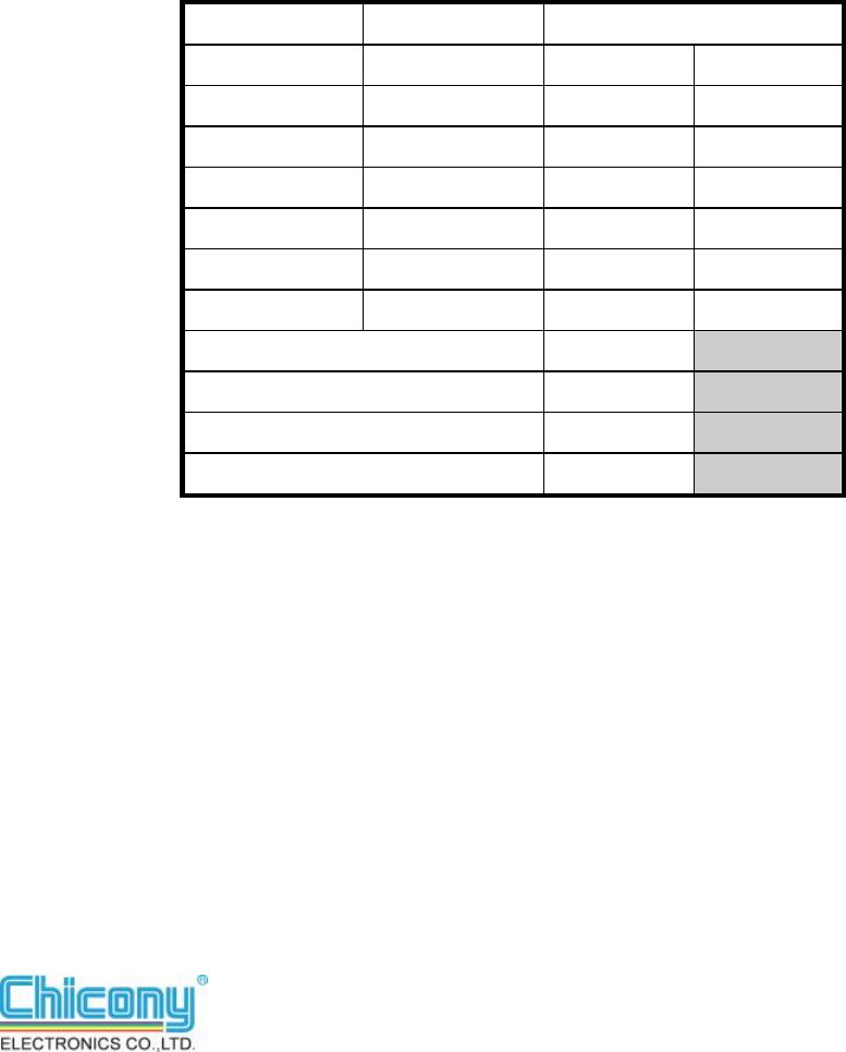
Mode Standard Current (mA)
mA DAC
TX 1M 391 41
11M 238 41
6M 384 52
54M 384 52
HT20-MCS0 373 48
HT20-MCS7 373 48
HT40-MCS0 370 48
HT40-MCS7 371 48
RX 1M 249 41
11M 249 41
6M 243 52
54M 243 52
HT20-MCS0 245 48
HT20-MCS7 245 48
HT40-MCS0 245 48
HT40-MCS7 245 48

W725D0 802.11ABGN 2T2R USB Module Page 8 of 12
Test condition
OS:Windows XP
Channel 165:5825MHz
Standard:IEEE802.11A, AN
Input voltage for whole circuit:4.97V
TX uses continuous mode
5.2 Test result:
MP_Kit_RTL11n_DualMAC_9xD_USB_v019_20120307
Continuous TX/RX @ 5GHz
Mode Standard Current (mA)
mA DAC
TX 6M 377 46
54M 378 46
HT20-MCS0 369 42
HT20-MCS7 369 42
HT40-MCS0 395 42
HT40-MCS7 394 45
RX 6M 242 46
54M 241 46
HT20-MCS0 241 42
HT20-MCS7 243 42
HT40-MCS0 244 45
HT40-MCS7 244 45
W725D0 802.11ABGN 2T2R USB Module Page 9 of 12
Test condition
OS:Windows XP
Channel 6:2437MHz
Standard:IEEE802.11G,N
RF output connects with AP (D-Link DIR-635, 2T3R)
Input voltage for whole circuit:4.97V
Throughput test mode
Distance Limit: 1M (Signal & Quality 100%)
Test driver
Realtek,
RTL8192DU_Drv_1016.1.0413.2012_UI_1.00.0180.All_In_One_Driver_Merge
d_UI.L
5.3 Test result:Throughput test @2.4GHz
Mode Standard Current (mA)
Min Max
TX 54M 197 210
HT20-MCS7 380 411
HT40-MCS7 275 382
RX 54M 194 198
HT20-MCS7 186 201
HT40-MCS7 197 205
Uninstall Driver 20
Idle (Non Connect) 178
Idle (associated) 183
Driver disable 126

W725D0 802.11ABGN 2T2R USB Module Page 10 of 12
Test condition
OS:Windows XP
Channel 165:5825MHz
Standard:IEEE802.11A,N
RF output connects with AP (D-Link DIR-635, 2T3R)
Input voltage for whole circuit: 4.97V
Throughput test mode
Distance Limit: 1M (Signal & Quality 100%)
Test driver
Realtek,
RTL8192DU_Drv_1016.1.0413.2012_UI_1.00.0180.All_In_One_Driver_Merge
d_UI.L
8.4 Test result:Throughput test @5GHz
Mode Standard Current (mA)
Min Max
TX 54M 313 323
HT20-MCS7 332 356
HT40-MCS7 320 367
RX 54M 271 281
HT20-MCS7 240 278
HT40-MCS7 243 276
Uninstall Driver 21
Idle (Non Connect) 168
Idle (associated) 245
Driver disable 140
W725D0 802.11ABGN 2T2R USB Module Page 12 of 12
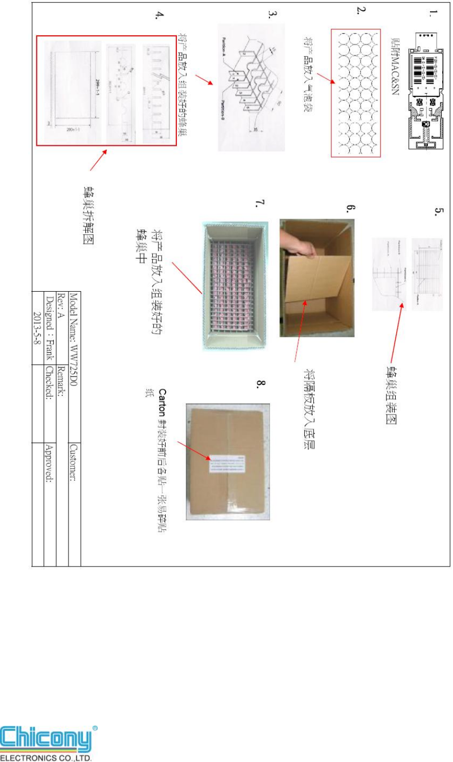
10. Package
2006/8/16 v1.0
Federal Communication Commission Interference Statement
This equipment has been tested and found to comply with the limits for a Class B digital device,
pursuant to Part 15 of the FCC Rules. These limits are designed to provide reasonable
protection against harmful interference in a residential installation. This equipment generates,
uses and can radiate radio frequency energy and, if not installed and used in accordance with the
instructions, may cause harmful interference to radio communications. However, there is no
guarantee that interference will not occur in a particular installation. If this equipment does
cause harmful interference to radio or television reception, which can be determined by turning
the equipment off and on, the user is encouraged to try to correct the interference by one of the
following measures:
- Reorient or relocate the receiving antenna.
- Increase the separation between the equipment and receiver.
- Connect the equipment into an outlet on a circuit different from that
to which the receiver is connected.
- Consult the dealer or an experienced radio/TV technician for help.
FCC Caution: Any changes or modifications not expressly approved by the party responsible for
compliance could void the user's authority to operate this equipment.
This device complies with Part 15 of the FCC Rules. Operation is subject to the following two
conditions: (1) This device may not cause harmful interference, and (2) this device must accept
any interference received, including interference that may cause undesired operation.
This transmitter must not be co-located or operating in conjunction with any other antenna or
transmitter.
Operations in the 5.15-5.25GHz band are restricted to indoor usage only.
IMPORTANT NOTE:
FCC Radiation Exposure Statement:
This equipment complies with FCC radiation exposure limits set forth for an uncontrolled
environment. This equipment should be installed and operated with minimum distance 20cm
between the radiator & your body.
Note: The country code selection is for non-US model only and is not available to all US model.
Per FCC regulation, all WiFi product marketed in US must fixed to US operation channels only.

2006/8/16 v1.0
This device is intended only for OEM integrators under the following conditions:
1) The antenna must be installed such that 20 cm is maintained between the antenna and users,
and
2) The transmitter module may not be co-located with any other transmitter or antenna.
As long as 2 conditions above are met, further transmitter test will not be required. However, the
OEM integrator is still responsible for testing their end-product for any additional compliance
requirements required with this module installed
IMPORTANT NOTE: In the event that these conditions can not be met (for example certain
laptop configurations or co-location with another transmitter), then the FCC authorization is no
longer considered valid and the FCC ID can not be used on the final product. In these
circumstances, the OEM integrator will be responsible for re-evaluating the end product
(including the transmitter) and obtaining a separate FCC authorization.
End Product Labeling
This transmitter module is authorized only for use in device where the antenna may be installed such
that 20 cm may be maintained between the antenna and users. The final end product must be labeled
in a visible area with the following: “Contains FCC ID: LNQ802RUN2”. The grantee's FCC ID can
be used only when all FCC compliance requirements are met.
Manual Information To the End User
The OEM integrator has to be aware not to provide information to the end user regarding how to
install or remove this RF module in the user’s manual of the end product which integrates this
module.
The end user manual shall include all required regulatory information/warning as show in this
manual.
Industry Canada statement:
This device complies with RSS-210 of the Industry Canada Rules. Operation is
subject to the following two conditions: (1) This device may not cause harmful
interference, and (2) this device must accept any interference received, including
interference that may cause undesired operation.
Ce dispositif est conforme à la norme CNR-210 d'Industrie Canada applicable aux
appareils radio exempts de licence. Son fonctionnement est sujet aux deux conditions
suivantes: (1) le dispositif ne doit pas produire de brouillage préjudiciable, et (2) ce
dispositif doit accepter tout brouillage reçu, y compris un brouillage susceptible de
provoquer un fonctionnement indésirable.
Caution :
(i) the device for operation in the band 5150-5250 MHz is only for indoor use to
reduce the potential for harmful interference to co-channel mobile satellite systems;
(ii) high-power radars are allocated as primary users (i.e. priority users) of the bands
5250-5350 MHz and 5650-5850 MHz and that these radars could cause interference
and/or damage to LE-LAN devices.
Avertissement:
(i) les dispositifs fonctionnant dans la bande 5 150-5 250 MHz sont réservés
uniquement pour une utilisation à l’intérieur afin de réduire les risques de
brouillage préjudiciable aux systèmes de satellites mobiles utilisant les mêmes
canaux;
(ii) De plus, les utilisateurs devraient aussi être avisés que les utilisateurs de radars de
haute puissance sont désignés utilisateurs principaux (c.-à-d., qu’ils ont la priorité)
pour les bandes 5 250-5 350 MHz et 5 650-5 850 MHz et que ces radars pourraient
causer du brouillage et/ou des dommages aux dispositifs LAN-EL.
FOR MOBILE DEVICE USAGE
Radiation Exposure Statement:
This equipment complies with IC radiation exposure limits set forth for an
uncontrolled environment. This equipment should be installed and operated with
minimum distance 20cm between the radiator & your body.
Déclaration d'exposition aux radiations:
Cet équipement est conforme aux limites d'exposition aux rayonnements IC établies
pour un environnement non contrôlé. Cet équipement doit être installé et utilisé avec
un minimum de 20 cm de distance entre la source de rayonnement et votre corps.
This device is intended only for OEM integrators under the following conditions: (For
module device use)
1) The antenna must be installed such that 20 cm is maintained between the antenna
and users, and
2) The transmitter module may not be co-located with any other transmitter or
antenna.
As long as 2 conditions above are met, further transmitter test will not be required.
However, the OEM integrator is still responsible for testing their end-product for any
additional compliance requirements required with this module installed.
Cet appareil est conçu uniquement pour les intégrateurs OEM dans les conditions
suivantes: (Pour utilisation de dispositif module)
1) L'antenne doit être installée de telle sorte qu'une distance de 20 cm est respectée
entre l'antenne et les utilisateurs, et
2) Le module émetteur peut ne pas être coïmplanté avec un autre émetteur ou
antenne.
Tant que les 2 conditions ci-dessus sont remplies, des essais supplémentaires sur
l'émetteur ne seront pas nécessaires. Toutefois, l'intégrateur OEM est toujours
responsable des essais sur son produit final pour toutes exigences de conformité
supplémentaires requis pour ce module installé.
IMPORTANT NOTE:
In the event that these conditions can not be met (for example certain laptop
configurations or co-location with another transmitter), then the Canada authorization
is no longer considered valid and the IC ID can not be used on the final product. In
these circumstances, the OEM integrator will be responsible for re-evaluating the end
product (including the transmitter) and obtaining a separate Canada authorization.
NOTE IMPORTANTE:
Dans le cas où ces conditions ne peuvent être satisfaites (par exemple pour certaines
configurations d'ordinateur portable ou de certaines co-localisation avec un autre
émetteur), l'autorisation du Canada n'est plus considéré comme valide et l'ID IC ne
peut pas être utilisé sur le produit final. Dans ces circonstances, l'intégrateur OEM
sera chargé de réévaluer le produit final (y compris l'émetteur) et l'obtention d'une
autorisation distincte au Canada.
End Product Labeling
This transmitter module is authorized only for use in device where the antenna may be
installed such that 20 cm may be maintained between the antenna and users. The final
end product must be labeled in a visible area with the following: “Contains IC:
2496A-802RUN2”.
Plaque signalétique du produit final
Ce module émetteur est autorisé uniquement pour une utilisation dans un dispositif où
l'antenne peut être installée de telle sorte qu'une distance de 20cm peut être maintenue
entre l'antenne et les utilisateurs. Le produit final doit être étiqueté dans un endroit
visible avec l'inscription suivante: "Contient des IC: 2496A-802RUN2".
Manual Information To the End User
The OEM integrator has to be aware not to provide information to the end user
regarding how to install or remove this RF module in the user’s manual of the end
product which integrates this module.
The end user manual shall include all required regulatory information/warning as
show in this manual.
Manuel d'information à l'utilisateur final
L'intégrateur OEM doit être conscient de ne pas fournir des informations à l'utilisateur
final quant à la façon d'installer ou de supprimer ce module RF dans le manuel de
l'utilisateur du produit final qui intègre ce module.
Le manuel de l'utilisateur final doit inclure toutes les informations réglementaires
requises et avertissements comme indiqué dans ce manuel.
Caution :
(i) the device for operation in the band 5150-5250 MHz is only for indoor use to
reduce the potential for harmful interference to co-channel mobile satellite systems;
(ii) high-power radars are allocated as primary users (i.e. priority users) of the bands
5250-5350 MHz and 5650-5850 MHz and that these radars could cause interference
and/or damage to LE-LAN devices.
Avertissement:
(i) les dispositifs fonctionnant dans la bande 5 150-5 250 MHz sont réservés
uniquement pour une utilisation à l’intérieur afin de réduire les risques de brouillage
préjudiciable aux systèmes de satellites mobiles utilisant les mêmes canaux;
(ii) De plus, les utilisateurs devraient aussi être avisés que les utilisateurs de radars de
haute puissance sont désignés utilisateurs principaux (c.-à-d., qu’ils ont la priorité)
pour les bandes 5 250-5 350 MHz et 5 650-5 850 MHz et que ces radars pourraient
causer du brouillage et/ou des dommages aux dispositifs LAN-EL.