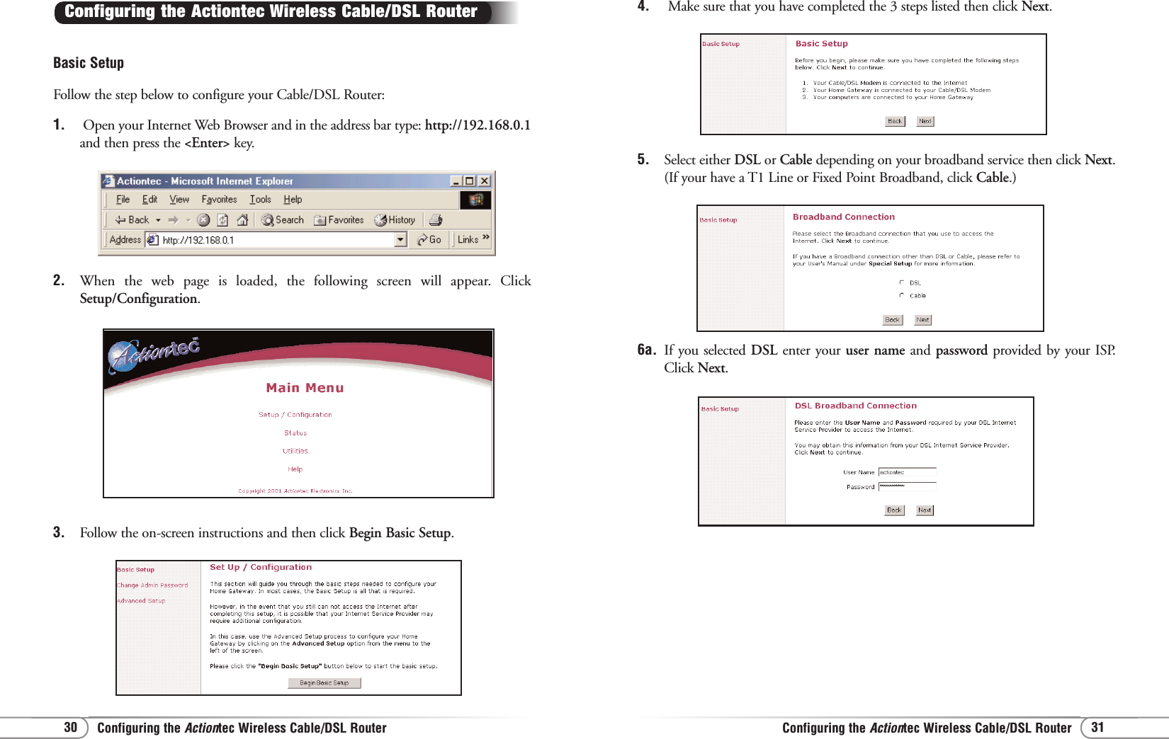
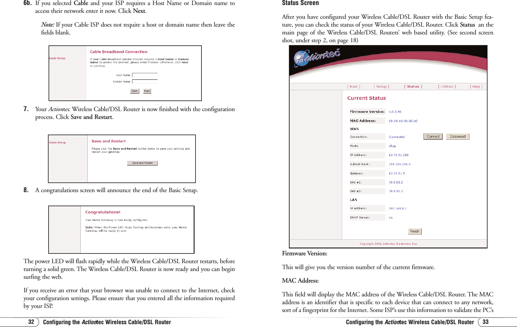
Actiontec Electronics R3010UW Ethernet Router User Manual Reno

Actiontec Electronics Inc Ethernet Router Reno
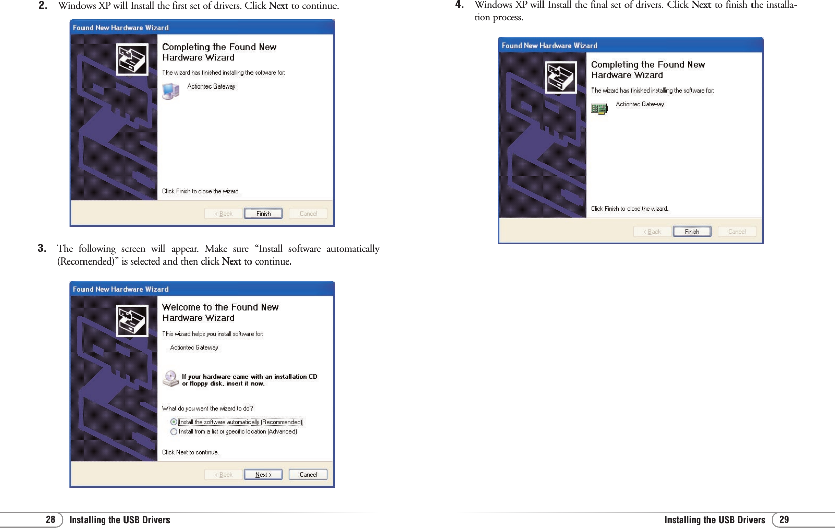
Users Manual

1Table of ContentsIntroduction 2Package Contents 2System Requirements 2Contacting Technical Support 3Introduction to the Wireless Cable/DSL Router 4Before you Connect the Wireless Cable/DSL Router 6Connecting the Actiontec Wireless Cable/DSL Router 17Installing the USB Drivers  18Configuring the Actiontec Wireless Cable/DSL Router 30Basic Setup 30Status Screen 33Advanced Configuration of the Wireless Cable/DSL Router 36WAN IP Address 38Wireless Settings 40LAN IP Address 42DHCP Server 42DHCP Server Configuration 43Services Blocking 43Website Blocking 44Remote Management 44Port Forwarding 45DMZ Hosting 45MAC Address Cloning 46Utilities 47Troubleshooting 49Glossary 50Specifications 53Environmental 54Appendix A 55Appendix B 68Appendix C 78Appendix D 81Table of Contents0530-????-000Page
2 3Contacting Technical SupportIntroductionActiontec Electronics prides itself on making high-quality, durable, high-performanceproducts. If you should need assistance, the Actiontec Technical Support Department isavailable 6 am to 11pm Mon - Sun (Mountain Time), to provide professional support.Contacting Technical SupportActiontec Electronics, Inc.760 N. Mary Avenue Sunnyvale, CA 94086Technical SupportPhone: 1-719-884-8300E-mail: techsupp@actiontec.comWebsite: www.actiontec.com/support Thank you for purchasing the Actiontec Wireless Cable/DSL Router. The WirelessCable/DSL Router is the simplest way to connect a small number of PC’s to a singlehigh speed Broadband modem. This easy to use product is perfect for the home officeor small business. If you would like to take your computing to the next level then theActiontec Wireless Cable/DSL Router is the key to your success.Package ContentsOne Actiontec Wireless Cable/DSL Router 4-Port Ethernet/USBOne Actiontec Wireless Cable/DSL Router 1-Port Ethernet/USBOne power adapter One RJ-45 Ethernet cableOne USB Cable Installation CDThis User’s Manual and Quick Start GuideWarranty & Registration CardMinimum System RequirementsBroadband Internet connection using an external Ethernet modemPC with an 10Mbps or 10/100Mbps Ethernet connectionMicrosoft Windows 95, Microsoft Windows 98, Microsoft Windows SecondEdition (SE), Microsoft Windows Millennium (ME), Microsoft Windows NT4,Microsoft Windows 2000, Microsoft Windows XP, MacOS 7.1+, MacOS 8.0+,MacOS 9.0+, or MacOS X+ (Note:  USB LAN port is not supported onMicrosoft Windows 95, Microsoft Windows NT 4.0and MacOS)Internet Explorer 4.0 or higher (5.x recommended) or Netscape Navigator 4.0or higher (4.7 recommended)TCP/IP Network Protocol installed on each computerIntroduction
5Introduction to the Wireless Cable/DSL Router4Introduction to the Wireless Cable/DSL RouterDescription of the LEDs and Reset Switch for the Wireless Cable/DSL Router 4-Port Ethernet/USB (GE144000-01) Power LED: The Power LED displays the Gateway’s current status. If the LED issolid green the Gateway is powered and fully operational. When the LED is rapidlyflashing, the Gateway is initializing.  If the LED is not illuminated when the poweradapter is plugged in, the Gateway has suffered a critical error and you should con-tact Technical Support.Internet LED:  When the Internet LED is steadily illuminated, the Gateway is con-nected to your broadband modem.Wireless LED: When the Wireless LED is steadily illuminated, the Gateway is readyfor wireless networking.Ethernet Network LED: The Ethernet Network LEDs illuminate when a networklink is established with a computer.  A flashing LED signifies network traffic acrossthat specific Ethernet connection.Reset Switch: Depressing the reset switch for 1-2 seconds will reset the Home DSLGateway.  To restore the default configuration settings inside the Gateway, depressand hold the reset switch for 10 seconds.Description of the LEDs and Reset Switch for the Wireless Cable/DSL Router1-Port Ethernet/USB (GE344000-01)Power LED: The Power LED displays the Gateway’s current status. If the LED issolid green the Gateway is powered and fully operational. When the LED is rapid-ly flashing, the Gateway is initializing.  If the LED is not illuminated when thepower adapter is plugged in, the Gateway has suffered a critical error and youshould contact Technical Support.Internet LED:  When the Internet LED is steadily illuminated, the Gateway is con-nected to your broadband modem.Wireless LED: When the Wireless LED is steadily illuminated, the Gateway is readyfor wireless networking.Introduction to the Wireless Cable/DSL Router LAN LED: The LAN LED will illuminate when a network link is established with acomputer.  A flashing LED signifies network traffic across the Ethernet connection.USB LED: The USB LED will illuminate when you connect the router to your com-puter using a USB cable.Reset Switch: Depressing the reset switch for 1-2 seconds will reset the WirelessCable/DSL Router.  To restore the default configuration settings inside the Gateway,depress and hold the reset switch for 10 seconds.
7Before you Connect the Wireless Cable/DSL Router6Before you Connect the Wireless Cable/DSL Router3.  The following screen will appear. Click Details to continue.You will need specific information from your ISP to configure the Wireless Cable/DSL Router.You can obtain most of this information from your broadband configured PC by following these4 steps. (Windows XP instructions shown below. For all other Operating Systems please seeApendix A at the back of this manual)Note:  If you have previously installed Internet Connection Sharing (Ex.Microsoft ICS) or Proxy Server software (Ex. WINPROXY) you will need touninstall them now.1.  Click Start, then Settings and finally Network Connections.Before you Connect the Wireless Cable/DSL Router  2.  On the right hand side of the screen, left click once on you the LAN or high speedinterenet connection that is listed. Then on the left hand side of the screen clickView status of this Connection.
9Before you Connect the Cable/DSL Router8Before you Connect the Cable/DSL RouterYour Host/Computer name and Workgroup name (Your ISP may use this informationto verify your identity on their network) (Cable only)___________________________          ___________________________Host Name  __________________________  (Example: CY57640-A.cospgs1.co.home.com)DNS Servers       ______.______.______.______  (Example: 24.5.68.33)Your Secondary DNS server address    ______.______.______.______ (Click on the ... button to change the listing)IP address  __________________________ (Example: 24.253.117.45)Subnet Mask (If assigned)   ______.______.______.______(Example: 255.255.255.0)For a listing of the information required for the major broadband ISP’s, pleasevisit the following Website and select your specific ISP. Please make sure thatyou have this information available when you configure the ActiontecWireless Cable/DSL Router.HTTP://www.actiontec.com/support/homegateway/index.html4.  The Network Connection Details screen will supply you with neccessary informa-tion. Write down this information for installation and future reference:Default Gateway (If assigned)   ______.______.______.______(Example: 24.253.117.1)Adapter Address   _____-_____-_____-_____-_____-_____(Example: 00-20-78-0F-B8-F0)Your LOGIN name and PASSWORD (DSL only, provided by your ISP)___________________________          ___________________________ Mail and Web Server InformationSome broadband providers use single words to direct the connection to their E-mail orweb servers (i.e. web, mail, pop3, www). If your ISP uses single words rather than awhole internet address (pop.mail.actiontec.com), or IP address (24.55.224.34), thenyou will need the full address information to configure your internet browser and/or E-mail clients.If this information was not provided during the installation and configuration of yourbroadband connection, then you will need to contact your ISP and ask for it.
11Before you Connect the Cable/DSL Router10 Before you Connect the Cable/DSL Router4.  Under the General tab select Obtain an IP address automatically, then selctObtain DNS server automatically. Click OK.3. In the Local Area Connection Properties window  select TCP/IP and then clickProperties. If there is not a listing for TCP/IP then refer to Appendix B for instal-lation instructions now. If there are no Ethernet Adapters listed, then refer to theEthernet card manufacturer for installation instructions.Configuring your Computer for NetworkingBefore configuring the Wireless Cable/DSL Router, a computer must be configured forstandard networking. If you are not running Windows XP, (shown below), then refer toAppendix A for information on configuring other Windows or MacOS based operatingsystems. It may be necessary to have the Windows CD or Ethernet card driver disketteto complete the configuration.1. Click  Start, then Settings  and finallyNetwork Connections.2.  On the right hand side of the screen, left click once on you the LAN or high speedinterenet connection that is listed. Then on the left hand side of the screen clickChange settings of this Connection.
13Before you Connect the Wireless Cable/DSL Router12 Before you Connect the Wireless Cable/DSL Router6. The System Properties window will appear. Click the Computer Name tab. The“Computer Description” field can be anything you want. (A location name or themain user’s name is generally used) Click Change.5. On your computer’s desktop right click on My Computer and select  Propertiesfrom the given list.7. Type your chosen computer name in the given field. The “Computer name” fieldmust have a 15 character limit and must be unique. Make sure that Workgroup isselected, and then type in the name of your workgroup. The “Workgroup” fieldmust have the same name on all computers attached to your network. Click OKwhen you are finished. You will return to the same screen in step 6, click OK again.Please restart your computer even if you are not asked to.8. Once the computer restarts and Windows has finished loading, you will beprompted for a password. DO NOT PRESS ESCAPE. This is the password thatWindows will use to authenticate your permission to be on the network. The pass-word you enter now will become your permanent network password. You may alsojust press OK or <Enter> and your password will be set to blank.Note: This password will be required each time you restart Windows.Repeat steps 1 thru 8 for each PC connected to your network.Ensure you use the same Workgroup name on each PC.
Before you Connect the Wireless Cable/DSL RouterBefore you Connect the Wireless Cable/DSL Router 15144. Click on Proxies and ensure that Direct connection to the Internet is selected.5. Click OK to close the Preferences window.Configuring Your Internet BrowserIf “Internet Explorer” is your default browser:1. Click Start, click Settings, select Control Panel.2. Double click Internet Options, select the Connections tab.3. Click LAN Settings. Remove any checks from the 3 boxes and click OK.4. Click OK to close the Internet Properties window.5. Close the Control Panel window.If “Netscape Navigator” is your default browser:1. Open Netscape Navigator.2. From the top menu bar select Edit and then click Preferences.3. Under the Category windows click on the + (plus icon) next to Advanced.
Connecting the Actiontec Wireless Cable/DSL RouterConnecting the Actiontec Wireless Cable/DSL Router 1716For Ethernet Connection:1. Please start up your computer.2. After your computer has started up, locate the blue Ethernet cable marked"Ethernet cable". Connect the cable to the back of the Actiontec WirelessCable/DSL Router and then to your Computer, into the Ethernet slot.3. Plug the Power Supply into a wall outlet, then plug the other end to the portlabeled “Power”, on the back of the Actiontec Wireless Cable/DSL Router.The Actiontec Wireless Cable/DSL Router allows you to connect to your computer intwo (wired) ways, by USB cable or Ethernet cable, and wireless. Follow these instruc-tions for the connection you choose:For USB Connection:1. Please start up your computer.2. After your computer has started up, locate the USB Cable. Connect the square end to theslot on the ActiontecWireless Cable/DSL Router labeled “USB”. On your PC, connectthe other, rectangular end to the appropriate USB slot.3. Plug the Power Supply into a wall outlet, then plug the other end to the portlabeled “Power”, on the back of the Actiontec Wireless Cable/DSL Router.Connecting the Actiontec Wireless Cable/DSL Router
19Installing the USB Drivers 18 Installing the USB Drivers 3. Click the box for CD-ROM drive. Before advancing to the next screen, insert theActiontec Gateway Installation CD-ROM into the computer’s CD-ROM drive.Finally, click the Next button.4. Windows will find the appropriate file on the CD-ROM. Click the Next button.For Windows 98Note: There are two drivers that will need to be installed, so please follow these instruc-tions1. After you have connected the Wireless Cable/DSL Router to your computer, theAdd New Hardware Wizard screen will appear. Click Next to continue.Installing the USB Drivers 2. Select the option “Search for the best driver for your device (Recommended)” andthen click the Next button.
21Installing the USB Drivers 20 Installing the USB Drivers 6. Select the option “Search for the best driver for your device (Recommended)” andthen click Next.7. Click the box for CD-ROM drive. and then click the Next button.5. Windows will install the first drivers needed for your computer. Click the Finishbutton to continue.6. The following screen will appear. Click Next to install the second driver.
23Installing the USB Drivers 22 Installing the USB Drivers For Windows ME Note: There are two drivers that will need to be installed, so please follow these instruc-tions1. After you have connected the Wireless Cable/DSL Router to your computer, theAdd New Hardware Wizard screen will appear. Make sure “Automatic search...” isselected and then click Next to continue.2. Windows will install the first drivers needed for your computer. Click the Finishbutton to continue.8. Windows will find the appropriate file on the CD-ROM. Click the Next button.9. Click Finish to end the installation process.10. When the following screen appears, click Yes to restart your computer.
25Installing the USB Drivers 24 Installing the USB Drivers For Windows 2000Note: There are two drivers that will need to be installed, so please follow these instruc-tions1. After you have connected the Wireless Cable/DSL Router to your computer, theFound New Hardware Wizard screen will appear. Click Next to continue.2. Select the option “Search for a suitable driver for my device (Recommended)” andthen click the Next button.3. Make sure “Automatic search...” is selected and then click Next to continue.4. Click Finish to end the installation process.5. When the following screen appears, click Yes to restart your computer.
27Installing the USB Drivers 26 Installing the USB Drivers 5. Click Finish to end the installation process.For Windows XPNote: There are two drivers that will need to be installed, so please follow these instruc-tions1. After you have connected the Wireless Cable/DSL Router to your computer, theFound New Hardware Wizard screen will appear. Make sure “Install software auto-matically (Recomended)” is selected and then click Next to continue.3. Click the box for CD-ROM drive. Before advancing to the next screen, insert theActiontec Gateway Installation CD-ROM into the computer’s CD-ROM drive.Finally, click the Next button.4. Windows will find the appropriate file on the CD-ROM. Click the Next button.
29Installing the USB Drivers 28 Installing the USB Drivers 4. Windows XP will Install the final set of drivers. Click Next to finish the installa-tion process.2. Windows XP will Install the first set of drivers. Click Next to continue.3. The following screen will appear. Make sure “Install software automatically(Recomended)” is selected and then click Next to continue.
Configuring the Actiontec Wireless Cable/DSL RouterConfiguring the Actiontec Wireless Cable/DSL Router 31304. Make sure that you have completed the 3 steps listed then click Next.5.  Select either DSL or Cable depending on your broadband service then click Next.(If your have a T1 Line or Fixed Point Broadband, click Cable.) 6a.  If you selected DSL enter your user name and password provided by your ISP.Click Next.3. Follow the on-screen instructions and then click Begin Basic Setup.Basic SetupFollow the step below to configure your Cable/DSL Router:1. Open your Internet Web Browser and in the address bar type: http://192.168.0.1and then press the <Enter> key.Configuring the Actiontec Wireless Cable/DSL Router 2.  When the web page is loaded, the following screen will appear. ClickSetup/Configuration.
Configuring the Actiontec Wireless Cable/DSL Router Configuring the Actiontec Wireless Cable/DSL Router 3332Status ScreenAfter you have configured your Wireless Cable/DSL Router with the Basic Setup fea-ture, you can check the status of your Wireless Cable/DSL Router. Click Status  an themain page of the Wireless Cable/DSL Routers’ web based utility. (See second screenshot, under step 2, on page 18)Firmware Version:This will give you the version number of the current firmware. MAC Address:This field will display the MAC address of the Wireless Cable/DSL Router. The MACaddress is an identifier that is specific to each device that can connect to any network,sort of a fingerprint for the Internet. Some ISP’s use this information to validate the PC’s6b. If you selected Cable and your ISP requires a Host Name or Domain name toaccess their network enter it now. Click Next.Note: If your Cable ISP does not require a host or domain name then leave thefields blank.7. Your Actiontec Wireless Cable/DSL Router is now finished with the configurationprocess. Click Save and Restart.8. A congratulations screen will announce the end of the Basic Setup. The power LED will flash rapidly while the Wireless Cable/DSL Router restarts, beforeturning a solid green. The Wireless Cable/DSL Router is now ready and you can beginsurfing the web.If you receive an error that your browser was unable to connect to the Internet, checkyour configuration settings. Please ensure that you entered all the information requiredby your ISP.
Configuring the Actiontec Wireless Cable/DSL RouterConfiguring the Actiontec Wireless Cable/DSL Router 3534This is the primary Domain Name Server address. This is like a telephone bookof all internet addresses.DNS #2This is the secondary Domain Name Server address.LANIP AddressThe IP Address of the Wireless Cable/DSL Router as seen by the PC’s withinyour LAN.DHCP ServerOn: This means that all of your PC’s will receive their IP address and other con-figuration data from the Wireless Cable/DSL Router each time they connect.Off: This means that each machine is configured individually with an IP, subnetmask, gateway and DNS server information.identification before it will allow you to access its network.WANConnection:Connected: A valid connection through the Cable/DSL modem to the Internetexists.Connecting...: The Cable/DSL Router is trying to establish a connection withthe ISP.Disconnected: A valid connection to the Cable/DSL modem exists, but there isno connection to the Internet.Off: A valid physical connection to the Cable/DSL modem is not presentMode:Static: Static IP Address information for the connection that was entered in thesetup is being usedDHCP: The Wireless Cable/DSL Router is being assigned an IP address andbeing sent other connection information each time the connection to the ISP isrenewedPPPoE: The connection is being made through Point to Point Protocol. This isusually the case for DSL broadband.  IP AddressThe IP address currently assigned and being used by the Wireless Cable/DSLRouter to connect to the ISPSubnet MaskThe subnet mask being used is normally 255.255.255.0 (Class C IP Address)GatewayThis is the IP address that the Wireless Cable/DSL Router uses to send allrequests to the Internet. DNS #1
Advanced Configuration of the Wireless Cable/DSL RouterAdvanced Configuration of the Wireless Cable/DSL Router 37364. Click on Begin Advanced Setup.5.  You will see the following screen showing all the options available in AdvancedSetup. If you want to check all the settings, or are unsure of which setting you wantto modify, select Next. If you want to modify a specific configuration, simply clickon its name in the left menu bar.Note: You may click Save and Restart on the bottom left hand side of the screenwhen you have finished configuring any one or more of the advance settings.3. Follow the on-screen instructions and then click Advanced Setup.The Advanced Setup section allows advanced users to configure such features as thewireless settings. The following sections explain each feature you can configure in theadvanced setup section.1. Open your Internet Web Browser and in the address bar type: http://192.168.0.1and then press the <Enter> key.Advanced Configuration of the Wireless Cable/DSL Router 2.  When the web page is loaded, the following screen will appear. ClickSetup/Configuration.
Advanced Configuration of the Wireless Cable/DSL RouterAdvanced Configuration of the Wireless Cable/DSL Router 3938Note: For the Host Name and Domain Name you may also find this informa-tion from your PC which was originally connected to the cable modem. Pleasesee the Before you Begin section on pages 6-7. If your cable modem ISP does notrequire these settings, then you may leave them blank.Specify a Static IP AddressThis setting is used if you have been assigned a static (Specific) IP Address by your ISP.You will need to enter the IP Address and Default Gateway provided by your ISP. Youmay also need to enter your Host Name and Domain Name if required. with their host name and/or domain name. Please check with your ISP for what hostname and domain name you have to use in the following fields.IP Address: IP Address of your Wireless Cable/DSL Router as seen by externalusers on the Internet.Subnet Mask: This will be provided by your ISP.Default Gateway: This will be provided by your ISP.Wan IP AddressThis screen allows you to manually set up your Wireless Cable/DSL Router. The fol-lowing are three methods by which your ISP will assign an IP Address to your WirelessCable/DSL Router.Note: Some DSL providers use PPPoE to establish communication with an enduser, while others use static IP. Cable modem providers and other broadbandInternet access such as fixed point wireless may use either DHCP or Static IPaddress. If you are unsure, please check with your ISP.Obtain and IP Address through PPPoEThis setting is used for DSL connections and it allows the modem to use the Point-to-Point over Ethernet (PPPoE) protocol. If you already entered the user name and pass-word in the Basic Setup, then it should be displayed now. Click Next to continue. User Name: User name given to you by your DSL provider to access the Internet.Password: Password given to you by your DSL provider to access the Internet. Obtain an IP through DHCPThis setting is used for Cable modem configurations that do not have a Static IPassigned by the ISP. This allows the modem to query the ISP and receive an IP addressand routing information. Some cable modem providers need to authenticate the users
Advanced Configuration of the Wireless Cable/DSL RouterAdvanced Configuration of the Wireless Cable/DSL Router 4140128-bit Wireless Equivalent Privacy (WEP)The 128-bit encryption requires a single field of 13 hexadecimal pairs (A hexadecimaldigit consists of alphanumeric characters in the range 0-9 or A-F). An example of 128-bit encryption would be: 3D-44-FE-6C-A1-EF-2E-D3-C4-21-74-5D-B1.If you docreate this key, make sure you enter it in your Wireless PC Card exactly as you have itin the Wireless Cable/DSL Router.Note: Do not use the 128-BIT WEP Key if your PC Card does not support it.64-bit Wireless Equivalent Privacy (WEP)The 64-bit eencryption requires 4 fields of 5 hexadecimal pairs. (A hexadecimal digitconsists of alphanumeric characters in the range of  0-9 or A-F). An example of 64-bitencryption would be: 4E-23-3D-68-72. If you do create this key, make sure you enterit in your Wireless PC Card exactly as you have it in the Wireless Cable/DSL Router.Wireless SettingsThe Wireless Settings screen allows you to take advantage of the Wireless Cable/DSLRouter’s wireless capabilities. ESSID (Default value set to ACTIONTEC) This is an arbitrary network name that you assignto your wireless network. You may use alphanumeric characters (i.e.: A-Z, a-z, 0-9). Itis important that you set your Wireless PC Cards to the same ESSID value. (For theActiontec 802.11b Wireless PC Card the ESSID value should be the same as the SSIDvalue) This will enable the Wireless PC Cards to communicate with your WirelessCable/DSL Router. Channel This assigns the frequency band in which the Wireless Cable/DSL Router can commu-nicate at. In the United States you may use channels 1-11. (Default value set to 1) Wireless Equivalent Privacy (WEP) This is an encryption method used in the 802.11b standard, to ensure data security overyour wireless network. The Actiontec Wireless Cable/DSL Router offers three levels ofencryption.If you do not require the encryption, it is recommended that you keep thisfeature disabled (off). It is not required for wireless operation, and can reduce networkperformance since each piece of data must be encrypted and decrypted.
Advanced Configuration of the Wireless Cable/DSL RouterAdvanced Configuration of the Wireless Cable/DSL Router 4342DHCP Server Configuration Beginning IP AddressEnter the IP Address for the DHCP Server to start when assigning IP Address. It is rec-ommended that you keep the default settings of 192.168.0.2Ending IP AddressEnter the IP Address for the DHCP Server to end when assigning IP Address. It is rec-ommended that you keep the default settings of 192.168.0.254DNS Server 1Enter the primary DNS provided by your ISP. You may keep the default settings if youwish.DNS Server 2Enter the secondary DNS provided by your ISP. You may keep the default settings if youwish.Services BlockingThis screen enables you to create Client or Internet privileges for certain computers’ onyour network. If you do not specify any settings then all of the computers on your net-work will have full priviledges.LAN IP AddressThis is the IP Address of the Wireless Cable/DSL Router as seen on the internal LAN.It is recommended that you keep the default settings, but if you need to change themthen be sure to verify the DHCP Server range is within the same subnet.DHCP ServerYour Wireless Cable/DSL Router has a built-in Dynamic Host Configuration Protocol(DHCP) Server that can automatically assign an IP Address to each computer on yournetwork.It is highly recommended that you keep the default DHCP Server settings. If you wishto disable your DHCP Server, select Off. You will need to ensure that the IP Address ofyour computers are in the same subnet as that of the Wireless Cable/DSL Router. To bein the same subnet, the IP address must begin with the same numbers for the first 3fields. (Example: 192.168.0.1 would mean your IP address would have to be192.168.0.x, with x being 2 - 254.)
Advanced Configuration of the Wireless Cable/DSL RouterAdvanced Configuration of the Wireless Cable/DSL Router 4544DMZ HostingDMZ hosting is used to support online gaming and Internet confrencing services. Theseprograms usually require multiple ports to be open on the Wireless Cable/DSL Router,making the rest of your network vulnerable to the Internet. DMZ hosting will symbol-ically place the designated computer (By IP address) outside of the Wireless Cable/DSL1. Find out the WAN IP Address of your Wireless Cable/DSL Router from the Statuspage.2.  From a location outside of  your network, open your Internet browser. In theaddress field type your WAN IP address (i.e. http//192.123.4.1) and press <Enter>.This will bring up your Wireless Cable/DSL Router menu or password prompt (ifa password has been set.Port ForwardingBecause the Wireless Cable/DSL Router is acting as a firewall for your network, someprograms may not be able to communicate over the Internet without some additionalconfiguration. This feature is useful if you want to host a webserver or ftp server on yourprivate LAN. You will need to open each port that your programs need and specify to aspecific IP (Computer). It is recommended that if you need to open more than 10 portsat once to use DMZ hosting instead. For a listing of commonly used programs and theirport numbers refer to Appendix C or the Actiontec web site.Remote ManagementThe Remote Management feature allows users to access the Wireless Cable/DSL Routerthrough the Internet. It is recommended that you do not alter the Remote Managementproperties. For security reasons, it is disabled by default.To access the Wireless Cable/DSL Router from the Internet:1. Enter the clients IP address in the given field.2. At the bottom of the page select the Internet services that you want blocked for thatparticular client PC.3. Click Add to place your choice in the “Blocked IP Address List”.4. If you would like to remove any of the blocked services, click on the IP Address inthe “Blocked IP Address List” and click Remove. Website BlockingThis feature enables you to block specific websites. Simply enter the name of the web-site into the appropriate field and click Add. When the user tries to access a blockedwebsite, the website will not be displayed. If you would like to remove a blocked web-site, click on it in the “Blocked Website List” and then click Remove.Note: Once a blocked website is selected, no user on the network will be able toaccess that site
UtilitiesAdvanced Configuration of the Wireless Cable/DSL Router 4746On the main screen of your Wireless Cable/DSL Router you will find a section calledUtilities. This section allows you to view your Web Activity Log, Restore DefaultSettings and Upgrade your Firmware. Follow the steps in each section below to use thesefeatures:Utilities Web Activity LogThis allows you to view the websites that each computer connected to your WirelessCable/DSL Router, has viewed.1.  Click on Utilities2.  Click on Web Activity Log. Router. You will be unable to access your network resources while in the DMZ. It is rec-ommended to place the computer in the DMZ mode only as long as it is necessary. Youwill also be unable to access your network resources.WARNING: This computer will be vulnerable to outside hackers while in theDMZ mode.MAC Address CloningThe MAC address is an identifier that is specific to each device that connects to anynetwork, simular to a fingerprint for the Internet. Some ISP’s require this informationto validate a computers permission to be on the network. If your ISP requires this infor-mation, you will need to determine the MAC address of the computer that was origi-nally configured for your service (Appendix D has instructions to determine the MACaddress).
TroubleshootingUtilities 4948There is a LAN connection failure to the Wireless Cable/DSL Router.Make sure that the Wireless Cable/DSL Router is properly installed, the LAN con-nections are correct and the power is on. Next, confirm that your PC and theWireless Access Point and Gateway are on the same network segment. If you arenot sure, let the PC get the IP address automatically by initiating the DHCP func-tion. Then, verify that your PC is using an IP address within the default range of192.168.1.2 to 198.168.1.XXX. If your PC is not using an IP address within therange then it will not be compatible with the Gateway. Finally, the Subnet Maskmust be set to 255.255.255.0 to match the Gateway. In the Gateway you can checkthis by clicking on Status on the Wireless Cable/DSL Routers start page.I am unable to browse through the Wireless Cable/DSL Router.First, make sure that both ends of the power adapter and network cables are prop-erly connected and the status LEDs on the front panel are infact working proper-ly. Then, if you are using Windows 95 or 98, check your computer’s TCP/IP setup:On your desktop click Start, then select Run, type winpcfg in the given box andthen hit Enter. Your computer should have an IP address of 192.168.XXX (the“XXX” value could be from 2 to 254.) Also the Subnet Mask should be255.255.255.0. Then, check the Wireless Cable/DSL Router settings to verify thatthey are the same as your computer. You can do this by clicking on Status on theWireless Cable/DSL Routers start page.I get a time out error when I enter a URL or IP Address,First, verify that all your computers are working properly. Then make sure that allyour IP settings are correct. If you are still having trouble make sure that theWireless Cable/DSL Router is on and connected properly. If it is connected prop-erly open up your web browser and access the Wireless Cable/DSL Router’s startpage. Verify that the Wireless Cable/DSL Router settings are correct by clicking onStatus. If this too is properly configured then check your Cable or DSL modem byattempting to connect to the Internet. I am unable to get an IP Address from my Cable or DSL Modem.First, make sure that your Wireless Cable/DSL Router is properly connected toyour computer and is plugged in. Then, shut off your Cable or DSL modem andwait a few seconds. Turn it back on, wait for it to go through its self test and thencheck for the IP Address. Then, verify that your modem is DHCP compatible. Goto the Wireless Cable/DSL Router’s web based utility and make sure you enteredthe user name and password for either your DSL or Cable modem.TroubleshootingRestore Default SettingsThis allows you to restore your Wireless Cable/DSL Router to its original default set-tings. 1.  Click on Utilities2.  Click on Restore Default Settings.3. Click the Restore Default Settings button.Upgrading your FirmwareFrom time to time, Actiontec will post firmware upgrades to enhance your WirelessCable/DSL Router’s usability. To upgrade your Wireless Cable/DSL Router’sfirmware: 1.  Click on Utilities2.  Click on Upgrade Firmware. Follow the onscreen instructions.3.  After downloading the upgrade files and extracting it to a folder on your hard drive,double click on upgrade.exe.4. Input the IP address of your Wireless Cable/DSL Router (typically it will be192.168.0.1), and click Start. The upgrade progress will begin.5.  After the Upgrade is complete, unplug the power from the Wireless Cable/DSLRouter then re-plug it. 6. Wait for the power LED to stop blinking and become a steady green.7.  You will need to reconfigure your Wireless Cable/DSL Router settings.
GlossaryGlossary 5150ESSID (Extended Service Set Identifier)You must have the same ESSID entered into the gateway and each of its wireless clients.The ESSID is a unique identifier for your wireless network. EthernetEthernet networks are connected by cables and hubs, and move data around. This is astandard for computer networks. FirewallA Firewall prevents anyone outside of your network from accessing your computer andpossibly damaging or viewing your files.GatewayA central device that manages all the data traffic of your network, as well as to theInternet.IP Address (Internet Protocol) An IP address consists of a series of four numbers separated by periods, that identifies aunique Internet computer host. ISP Gateway Address (see ISP for definition)The ISP Gateway Address is an IP address for the Internet router. This address is onlyrequired when using a cable or DSL modem.ISP (Internet Service Provider)An ISP is a business that allows individuals or businesses to connect to the Internet.LAN (Local Area Network)A LAN is a group of computers and devices connected together in a relatively smallarea (such as a house or an office). Your home network is considered a LAN.MAC Address (Media Access Control)A MAC address is the hardware address of a device connected to a network.NAT (Network Address Translation)Access Point An access point is a device that allows wireless clients to connect to other wireless clientsand it acts as a bridge between wireless clients and a wired network’ like Ethernet.Wireless clients can be moved anywhere within the coverage area of the access point andstill connect with eachother. If connected to an Ethernet network, the access point mon-itors Ethernet traffic and forwards appropriate Ethernet messages to the wireless net-work, while also monitoring wireless client radio traffic and forwarding wireless clientmessages to the Ethernet LAN. ChannelThe home wireless gateway allows you to choose different radio channels in the wirelessspectrum. A gateway operates within the 2.4 GHz spectrum and a channel is within  aFCC specified range, simular to any radio channel.ClientA client is the desktop or mobile PC that is connected to your network.DHCP (Dynamic Host Configuration Protocol)This automatically assigns an IP address for every computer on your network.DNS Server Address (Domain Name System)DNS allows Internet host computers to have a domain name and one or more IPaddresses. A DNS server keeps a database of host computers and their respective domainnames and IP addresses, so that when a user enters a domain name into the internetbrowser, the user is sent to the proper IP address. The DNS server address used by thecomputers on your home network is the location of the DNS server your ISP hasassigned.DSL Modem (Digital Subscriber Line)A DSL modem uses your existing phone lines to transmit data at high speeds.EncryptionThis provides wireless data transmissions with a level of security.Glossary
Glossary Specifications 5352Model Number: GE344000-01  Wireless Cable/DSL Router 1-Port GE144000-01  Wireless Cable/DSL Router 4-Port Standards: IEEE 802.3 (10BaseT), IEEE 802.3u (100BaseTX), IEEE 802.11b (Wireless)Protocol: CSMA/CDWAN: One 10Base-T RJ-45 Port for Cable/DSL ModemLAN: (GE144000-01) Four 10/100 RJ-45 Switched Ports, One USBport (GE344000-01) One 10/10100 RJ-45One Shared Uplink Port, One USB portExpansion: One PCMCIA expansion slotSpeed: WAN - 10Mbps, LAN Ethernet - 10/100Mbps Wireless (See Below)Cabling Type: 10BaseT: UTP/STP Category 3 or 5100BaseTX: UTP/STP Category 5Button: ResetOperation Range:(Wireless)Indoors: Up to 30M (100 ft.) @ 11 MbpsUp to 50M (165 ft.) @ 5.5 MbpsUp to 70M (230 ft.) @ 2 MbpsUp to 91M (300 ft.) @ 1 MbpsOutdoors: Up to 152M (500 ft.) @ 11 MbpsUp to 270M (885 ft.) @ 5.5 MbpsUp to 396 (1300 ft.) @ 2 MbpsUp to 457M (1500 ft.) @ 1 MbpsTopology: Star (Ethernet)LED Indicators: 1-Port Router: Power, Internet, Wireless, LAN, USB 4-Port Router: Power, Internet, Wireless, Ethernet NetworkWAN: LinkLAN: Link/Activity SpecificationsThis process allows all of the computers on your home network to use one IP address.This will enable access to the Internet from any computer on your home network with-out having to purchase more IP addresses from your ISP.PC CardThis is an ethernet card that connects to the PCMCIA slot on your lap top or desktopPC. This enables the computer to communicate with with the Wireless Cable/DSLRouter.PPPoE (Point-to-Point Protocol over Ethernet.)Point-to-Point Protocol is a method of secure data transmission.Subnet MaskA subnet mask is a set of four numbers configured like an IP address. It is used to cre-ate IP address numbers used only within a particular network.TCP/IP (Transmission Control Protocol/Internet Protocol)This is the standard protocol for data transmission over the Internet.WAN (Wide Area Network)A network that connects computers located in separate areas, (i.e., different buildings,cities, countries). The Internet is a wide area network.WECA (Wireless Ethernet Compatibility Alliance)An industry group that certifies cross-vender interoperability and compatibility of IEEE802.11b wireless networking products and to promote that standard for enterprise,small business, and home environments.WLAN (Wireless Local Area Network)This is a group of computers and other devices connected wirelessly in a small area. Awireless network is referred to as LAN or WLAN.
Appendix AEnvironmental 5554Configuring TCP/IP For Windows NT 4.0Please make sure you have your Windows NT Workstation 4.0 installation disks or CD-ROM handy before beginning. Windows NT Workstation 4.0 may need to copy somedriver information during the configuration process. If your Ethernet card was suppliedwith a driver diskette, be sure to have that available as well.Note: As with all software, you should consult your users manual or the help filesfor detailed information. Actiontec provides the information that follows as aguideline only.Network, Username, Computer Name IdentificationTo configure your NT Workstation v 4.0 click Start, go to Settings and then to ControlPanel. In Control Panel, double-click the Network icon. In the Network dialog box,click the Identification tab and enter a Computer Name if needed and a Work Group.Note: Do not change both Computer name and Workgroup at the same time.Change one first and then restart. Then change the other and restart a secondtime.Appendix APower Input: External, 5V DC, 2.5 ACertifications: FCC Class B, FCC Class C, CE Mark Commercial, UL, Wi-FiOperating Temperature: 0º C to 40º C (32ºF to 104ºF)Storage Temperature: -20ºC to 70ºC (-4ºF to 158ºF)Operating Humidity: 10% to 85% Non-CondensingStorage Humidity: 5% to 90%, Non-CondensingEnvironmental
Appendix AAppendix A 5756TCP/IP Properties, IP Addressing, DHCPWith the TCP/IP Protocol highlighted, click Properties, and then click the IP Addresstab and click Obtain an IP Address from a DHCP Server. Click the Advanced tab toverify that DHCP is enabled.Services ConfigurationClick the Services tab, and make sure the following default services are listed. These areinstalled by default when you initially installed TCP/IP. Note that not all of the servic-es listed below are required for the Actiontec Wireless Cable/DSL Router. For addition-al information, refer to your NT Workstation documentation or Microsoft supportservices.Computer Browser RPC Configuration Server Workstation If you need to add a Service, click Add and do so.Protocol ConfigurationClick the PROTOCOLS tab, and then verify that the TCP/IP Protocol is listed. If it isnot, add it.
Appendix AAppendix A 5958Routing ConfigurationClick the Routing tab, and then verify that the Enable IP Forwarding is not checked.Click OK to return to the Network dialog box.DNS and Host Name SettingsClick the DNS tab to display the host name properties. WINS Address ConfigurationClick the WINS Address tab. Verify that the only entry here is your Ethernet card.(Please see the screen image on the next page.)
Appendix AAppendix A 6160Click OK, then click Close and restart your computer when prompted.ProtocolsSelect All Protocols from the drop down list in the Bindings tab. (This is not the sameas the Protocols tab)Expand all entries by clicking on plus (+) signsTCP/IP Protocol should be bound to the adapter WINS Client (TCP/IP) should be bound to the adapter Adapter SettingsClick the Adapters tab, and then verify that your Ethernet Card is listed. If your card isnot listed, please add it.Bindings Configuration: Protocols, Services, AdaptersThe Bindings tab contains a drop down list box that allows you to display differentviews of your networking configuration.ServicesClick the Bindings tab, select All Services from the drop down list, and verify that youhave at a minimum, TCP/IP bound to the Ethernet Card.
Appendix AAppendix A 6362Configuring TCP/IP for Windows 2000Please make sure you have your Windows 2000 installation disks or CD-ROM handybefore beginning. Windows 2000 may need to copy some driver information during theconfiguration process. If your Ethernet card was supplied with a driver diskette, be sureto have that available as well.Note: As with all software, you should consult your users manual or the help filesfor detailed information. Actiontec provides the information that follows as aguideline only.Windows 2000 installs with the default TCP/IP configuration. If you have a newmachine with Windows 2000, or have just installed the Operating System, you simplyneed to connect your machine to your Wireless Cable/DSL Router.If your Windows 2000 TCP/IP settings have been changed since installation, please fol-low the following directions. Also, make sure you have your Windows installation disksor CD handy before beginning. If your Ethernet card was supplied with a driverdiskette, be sure to have that available as well. (Note that Windows 2000 includes built-in drivers for some Ethernet cards) Note: As with all software, you should consult your users manual or the help filesfor detailed information. Actiontec provides the information that follows as aguideline only.To configure TCP/IP for Windows 2000:1. Click on Start, and then select Settings and then Control Panel. Double click theNetwork and Dial-Up Connections icon. 2. If the Ethernet card in your computer is installed correctly, the Local AreaConnection icon will be present. Double-click on the icon. Click Properties in theLocal Area Connection Status window.AdaptersSelect All Adapters from the drop down list in the Bindings tab.Expand all entries by clicking on plus (+) signsThe adapter should be bound to the TCP/IP Protocol WINS Client (TCP/IP) should be bound to Server and Workstation Verifying SettingsAfter you have restarted your computer, verify your settings. Click Start, selectPrograms and then select Command Prompt. At the command prompt, type "ipcon-fig/all" to verify that you received an IP address. You may close this window once youhave verified your IP address.
Appendix AAppendix A 65645. Click OK to finish 3.  Under Connect Using, the Ethernet card to which the Local Area Connection inquestion is pointing is displayed. Underneath, the components that are bound tothe card are shown, with a check box next to them if they are currently active. Verifythat there is a check next to TCP/IP, and place one there if it is not checked.Highlight the Internet Protocol (TCP/IP) option, and click Properties.4. The Internet Protocol (TCP/IP) Properties window will open. There is only onetab. Obtain an IP address automatically should be selected in the first section, andObtain DNS server address automatically should be selected in the second section.
Appendix A Appendix A 67665. Make sure the Use 802.3 option is unchecked.6.  Disregard any # in the IP Address field. This will be correct after your first con-nection. 7.  Click the Options button and set TCP/IP to Active. Uncheck the option Loadonly when needed, and click OK when finished.8. No entries should be made in any of the other fields (which are shown as blank inthe sample image above).9. Click Close Box in the upper left hand corner of the TCP/IP window, and thenselect Save to save your settings.10. Go to the toolbar and select Restart from the Special menu to restart your com-puter. Configuring TCP/IP For Mac OSAs with all software, you should consult your users manual or the Macintosh help filesfor detailed information. Actiontec provides the information that follows as a guidelineonly.Configuring Open Transport 2.5.2To configure Open Transport:1.  From the top toolbar, click the Apple icon. Select TCP/IP from the Control Panelsmenu.2.  Once the TCP/IP control panel is open, on the top toolbar click User Mode fromthe Edit menu, and set the mode to Advanced. When done, click OK. 3. In the Connect via selection, select Ethernet.4.  In the Configure selection, select Using DHCP Server.
69Appendix AConfiguring File and Print Sharing For Windows 95, 98 and MEWith your Wireless Cable/DSL Router you can establish a network that will allow youto share files and printers. This is an easy method to set up a network in your home orsmall office. Please follow these steps to setup file and print sharing:1. On your computer’s desktop click Start, then select Settings  and then selectControl Panel. In the “Control Panel” window double click the Network icon.2. The following “Network” screen should appear. If File and Print Sharing is notpresent, then click the Add button.Appendix B3. In the “Select Network Component Type” screen, click Service and then click theAdd button.68 Appendix AConfiguring MacOS X:To configure MacOS X for DHCP:1.  Open the System Preference application via the Dock or Apple Menu.2.  Select Built-In Ethernet from the Show menu.3.  In the TCP/IP tab, select Using DHCP from the Configure menu.4.  Click Apply Now and quit the System Preferences application.
71Appendix B70 Appendix A6. After you have clicked OK you will return to the network screen from step 2. Pleaseclick on the Identification tab (see the first image on page 26). Computer Name: In this field you can type any name you want. (i.e. MyComputer, John, CPU654) Do not use the same name for each computer youwish to have on your network, and we do not recommend including spaces inthe computer name.Workgroup: This field enables you to set a unique name for your network. Thisname must be set up on every other computer you wish to have on your net-work.Computer Description: You can enter anything you wish. Traditionally, thelocation name or main user’s name is used in this field.7. Click on the Configuration tab. This will take you back to the screen from step 2.In the “Primary Network Logon:” box, located just above the “File and PrintSharing” button, make sure that Client for Microsoft Networks is selected. If it isnot then click the down arrow and select it from the given list. Click OK.8. A screen will appear asking you to restart your computer. Click Yes to restart thecomputer. If you do not see this screen please restart your computer manually. After4. In the following screen please select File and printer sharing for MicrosoftNetworks from the given list. Click OK.5. In the “File and Print Sharing” screen make sure that both of the selections have acheck mark beside them. If they do not, please click on the box next to each state-ment and then click OK.
73Appendix B72 Appendix BRead Only: This will allow other users on your network to view and read the fileor drive you selected. They will not be able to modify it in any way. You can fur-ther restrict their privileges by entering a password in the appropriate field.Full: This will allow other users on your network to read, modify, move anddelete any information in the shared drive or file. You can further restrict theirprivileges by entering a user name and password.Depends on Password: This will allow you to set both Read Only and Full accesson the shared file or drive. The level of access will depend on the passwords youenter in the appropriate field.When you are finished click Apply and then OK.your computer restarts you will be asked to supply a User Name and Password.Enter whatever you would like but be sure to write down these values, as they willenable you to access your network. 9. After your computer has restarted and you entered a password and user name, youmust enable a file or drive for sharing. Locate the file or drive you wish to share.(The easiest way to achieve this is through your Windows Explorer, located in thestart menu) Right click on the File or Drive you wish to share. In the given menuselect Sharing.10. The following screen will appear. Please select Shared As. This will enable otherusers on your network to see the file or drive you selected. Then  you can chose theAccess Type:
75Appendix B74 Appendix B13. The next step will be to enable the sharing by selecting the “Share As” button. Itwill automatically insert a default name for the Share Name. You may set a pass-word for the printer at this time if you want to restrict who on the network can usethis resource. You may also set the default printer settings by modifying informa-tion on the other tabs of this window. For Windows 20001. After you have installed and configured your PC Card, Windows 2000 will auto-matically enable file and print sharing for your computer. The only item that needsto be altered is your workgroup settings. All the computers on your network musthave the same workgroup name but different computer names. To check or changethis locate the “My Computer” icon on your desktop. Right click on it and selectProperties from the given list.2. In the “System Properties” click on the Network Identification tab. If the“Workgroup” name is already the same as all the other computers on your network,then you do not need to change it. Click OK.  If it is not the same then clickProperties.11. Next you need to share your printer. On your desktop, click Start, click Settings,and then select Printers.12.  Right click on the printer you want to share. Select “Sharing” from the given list.
Appendix B 7776 Appendix Band the buttons underneath should both say “Start”. If this is the case, file sharingis disabled. Exit the File Sharing window. 3.  If “File Sharing Off” and “Program Linking Off” is selected and the buttonsunderneath indicate “Stop”, click the Stop button to disable sharing and linking.Enter 0in the dialog box that prompts you to indicate how many minutes until filesharing is turned off or how long before you want to disconnect other users con-nected to your computer. 4. Click OK5. Exit the File Sharing window. If you need to enable file sharing on your computer, you can reduce your susceptibilityto hackers by setting a password for access to all of your shared files and directories.To set a password:1.  Click the Apple menu in the upper left corner. Select Control Panels and thenselect File Sharing. 2.  Under “Network Identity”, enter an owner name and owner password. To deterpotential hackers from being able to guess your password, we recommend that yourpassword contain a minimum of eight characters and a mix of upper- and lower-case letters and numbers. 3. The two sections toward the bottom should say “File Sharing Off” and “ProgramLinking Off”, and the buttons underneath should both say “Start”. Click Start toenable file sharing and/or program linking. 4. The indication above the Start button(s) will change from “Off” to “Starting Up”to “On”. 5. Close the File Sharing window by clicking the small box in the upper left corner. 6. File sharing and/or program linking are now enabled. However, users will need toknow your Owner Name and Owner Password in order to access files or programson your Macintosh. To allow others to use the printer attached to your computer:1. Click the Apple menu in the upper left corner and scroll down to Control Panels;then scroll right and up to Appletalk. 3. In the “Computer Name:” box type a name that is different from your other PC’son your network. Then, in the “Workgroup” box type the name that you are usingto identify your network. This will be the same on each computer on your network.Click OK and you will return to the “Network Properties” screen. Click OK againand even if you are not asked to do so, please restart your computer.Configuring File and print sharing for MACThere are other, much more secure ways to share your files with other Internet users. Forexample, you can simply e-mail files you want to share with someone else directly to thatperson or you can require a password to access your files.Following are instructions for disabling and more securely enabling file and print shar-ing.To disable file sharing:1.  Click the Apple menu in the upper left corner. Select Control Panels and thenselect File Sharing. 2. The default selections should be “File Sharing Off” and “Program Linking Off”,
Appendix B Appendix C 7978Standard Program and Port List:Appendix CApplication Type Application Notes˚ Required Settings for Port ForwardingSERVICES NOTES Outgoing Connection Incoming ConnectionHTTP Netscape, IE None 80 /client IPFTP Windows FTP, Cuteftp None 21 /client IPTELNET Windows Telnet, Neterm None 23 /client IPPOP3 Eudora  None 110 /client IPSMTP Eudora None 25 /client IPmIRC mIRC None .Network Time Protocol (NTP)   123 123  /client IPPPTP Windows PPTP  None 1723 /client IPAPPLICATIONS NOTES Outgoing Connection Incoming ConnectionBAYVPN   500 /client IP  CarbonCopy32     1023 - 1680 /client IPCITRIX      1494 /client IPCu-SeeMe2Cornell 1.1 None 7648 /client IP.White Pine 3.1.2 7648 /client IP &24032 /client IP Default /client IP.White Pine 4.0(CuSeeMe Pro )7648 /client IP &24032 /client IPDefault /client IPDirect Connect     375 - 425 /client IPFW1VPN   259 /client IP  ICQ For file transfer, we must enable:ICQ -> preference -> connections -> firewall and set the firewall timeout to 80 seconds in firewallsetting.None for Chat.  Default /client IP2. In the drop-down menu after Connect via, choose Ethernet or Ethernet Built-In.3. Close the Appletalk window by clicking the small box in the upper left corner. 4. You may be asked to save changes to your Appletalk setting. If so, click the OK but-ton. 5. Click the Apple menu in the upper left corner and scroll down to Chooser; then,after the word Appltalk toward the bottom right, click the radio button before theword “Active”. 6.  You'll be asked to make sure you are connected to an Appletalk network. Click theOK button. 7. Close the Chooser window by clicking the small box in the upper left corner. Note: When print sharing is enabled, you cannot use a password to protect yourprinter. Therefore, we strongly recommend that your leave this option enabledonly during the time you wish to share your printer with other users. When theother users have finished printing their files on your printer, we recommend youreverse the above process. To do so, you need not change your Appletalk settingsagain. All you need to do is call up Chooser and disable Appletalk by clickingthe radio button before Inactive in the lower right corner.
Appendix CAppendix C 8180MSN Game Zone     6667 /client IP28800 - 29000 /client IPMSN Game Zone (DX)     2300 - 2400 /client IP47624 /client IPMyth     3453 /client IPNeed for Speed      9442 /client IPNeed for Speed 3     1030 /client IPOutlaws     5310 /client IPQuake I4   None Default /client IPQuakeII5  None 27910 /client IPQuakeIII  Each computer must use adifferent port number. Add 1 foreach player starting with 27660.None 27660 (+1 for each player) /cliIPRainbow Six   2346 /client IP 2346 /client IPRogue Spear   2346 /client IP 2346 /client IPStarCraft    6112 /client IPTiberian Sun   1140 - 1234 /client IP4000 /client IP1140 - 1234 /client IP4000 /client IPUltima   5001 - 5010 Game7775 - 7777 Login8888, 9999 Patch8800 - 8900 Messenger7875 MonitorUnreal TournamentNeed to modify the[UWeb.WebServer] section of theserver.ini file: Set ListenPort to8080; Set ServerName to thePublic IP of your router. 7777 (game) 7778 (server)7779 - 7783 (UdpLink)27900 (server query)8080 (UT Server Admin)IP/TV Cisco IP/TV 2.0.0 None .Laplink      1547 /client IPLotus Notes     1352 /client IPNetMeeting3Microsoft NetMeeting 2.1 & 2.11 None 1720 /client IP1503 /client IPPC Anywhere Host must be on the LAN side andclient IP set.  22 /client IP5631 - 5632 /client IPRealPlayer RealPlayer G2 None .Remote Anything     3996 - 4000 /client IPShiva VPN Need to set the mobile option to beyour public IP address. 2233 /client IP 2233 /client IPVirtual Network Computing(VNC)   5500 /client IP5800 /client IP5900 /client IPVDOLive .None .GAMES NOTES Outgoing Connection Incoming ConnectionAliens vs. Predator    80 /client IP2300 - 2400 /client IP8000 - 8999 /client IPAsheron's Call  May need to open MSN / DXports. 9000 - 9013 /client IP 9000 - 9013 /client IPBlack and White     2611 - 2612 /client IP6500 /client IP6667 /client IP27900 /client IPDark Reign 2     26214/client IPDelta Force  3100 /client IP3568 /client IP3999 /client IP  3100 /client IP3568 /client IP3999 /client IPDune 2000    1140 - 1234 /client IP4000 /client IP1140 - 1234 /client IP4000 /client IP  Elite Force    26000 /client IP27500 /client IP27910 /client IP27960 /client IPEverquest   1024 - 6000 /client IP7000 /client IPF-22 Lightning 3     4533 - 4660 /client IPFighter Ace II     50000 - 50100 /client IPFighter Ace II (DX)    2300 - 2400 /client IP47624 /client IP50000 - 50100 /client IPHalf Life      27015 /client IPHeretic II      28910 /client IPHexen IIEach computer must use a differentport number. Add 1 for each playerstarting with 26900.  26900 (+1 for each player)KALIEach computer must use a differentport number. Add 1 for each playerstarting with 2213. 2213 (+1 for each player) /clienIP6666 /client IP
Appendix D Appendix D 83827.  Make note of the Physical Address of the Ethernet Adapter (labeled 'PhysicalAddress') as it is the same as you MAC address To determine the MAC address of an installed Ethernet card on Windows NT: 1.  Click the Start menu 2.  Select Programs3.  Select Command Prompt4.  Type: ipconfig/all 5.  Press Enter6.  A window will display, with information pertaining to the Ethernet Adapter 7. Make note of the Physical Address of the Ethernet Adapter (labeled 'PhysicalAddress') as it is the same as you MAC address To determine the MAC address of an installed Ethernet card on a Macintosh: 1.  Select the Apple menu.2.  Select Control Panels3.  Select TCP/IP 4.  Select the Info button (If the Info button does not appear, select the Edit menu,then User Mode and then select Advanced) 5.  A window will display showing the hardware address 6.  Carefully make note of this Hardware address as it is the same as the MAC address To determine the MAC address of an installed Ethernet card on Windows95/98: 1. Click the Start menu 2.  Select Run3.  In the text field type: winipcfg4.  Click OK5.  An IP Configuration window will appear 6.  Carefully make note of the Adapter Address as it is the same as you MAC address To determine the MAC address of an installed Ethernet card on Windows ME: 1. Click the Start menu 2.  Select Run3.  In the text field type: winipcfg4.  Click OK5.  An IP Configuration window will appear 6.  Carefully make note of the Adapter Address as it is the same as you MAC addressTo determine the MAC address of an installed Ethernet card on Windows 2000: 1.  Click the Start menu 2.  Select Programs, and then Accessories3.  Select Command Prompt4. Type: ipconfig/all5.  Press Enter6.  A window will display, with information pertaining to the Ethernet Adapter Appendix D
FCC StatementFCC Statement 8584For questions regarding your product, or the FCC declaration, contact:Actiontec Electronics, Inc760 North Mary Ave,Sunnyvale, CA 94086United StatesTel: (408) 752-7700 Fax: (408) 541-9005Regulatory Compliance Notices Class B EquipmentThis equipment has been tested and found to comply with the limits for a Class B dig-ital device, pursuant to Part 15 of the FCC Rules.  These limits are designed to providereasonable protection against harmful interference in a residential installation. Thisequipment generates, uses, and can radiate radio frequency energy and, if not installedand used in accordance with the instructions, may cause harmful interference to radiocommunications.  However, there is no guarantee that interference will not occur in aparticular installation. If this equipment does cause harmful interference to radio or tel-evision reception, which can be determined by turning the equipment off and on, theuser is encouraged to try to correct the interference by one or more of the followingmeasures:Reorient or relocate the receiving antenna.Increase the separation between the equipment and receiver.Connect the equipment into an outlet on a circuit different from that to whichthe receiver is connected.Consult the dealer or an experienced radio or television technician for help.ModificationsThe FCC requires the user to be notified that any changes or modifications made to thisdevice that are not expressly approved by Actiontec Electronics, Inc may void the user’sauthority to operate the equipment.Declaration of conformity for products marked with the FCC logo – United States onlyThis device complies with Part 15 of the FCC Rules.  Operation is subject to the fol-lowing two conditions: (1) This device may not cause harmful interference, and (2) This device must accept any interference received, including interference that maycause undesired   operation."IMPORTANT NOTE: To comply with FCC RF exposure compliance requirementsthe antenna used for this transmitter must be installed to provide a separation distanceof at least 20 cm from all persons and must not be co-located or operating in conjunc-tion with any other antenna or transmitter." FCC Statement

Navigation menu