Actiontec Electronics R3010UW Ethernet Router User Manual Reno
Actiontec Electronics Inc Ethernet Router Reno
Users Manual

1
Table of Contents
Introduction 2
Package Contents 2
System Requirements 2
Contacting Technical Support 3
Introduction to the Wireless Cable/DSL Router 4
Before you Connect the Wireless Cable/DSL Router 6
Connecting the Actiontec Wireless Cable/DSL Router 17
Installing the USB Drivers 18
Configuring the Actiontec Wireless Cable/DSL Router 30
Basic Setup 30
Status Screen 33
Advanced Configuration of the Wireless Cable/DSL Router 36
WAN IP Address 38
Wireless Settings 40
LAN IP Address 42
DHCP Server 42
DHCP Server Configuration 43
Services Blocking 43
Website Blocking 44
Remote Management 44
Port Forwarding 45
DMZ Hosting 45
MAC Address Cloning 46
Utilities 47
Troubleshooting 49
Glossary 50
Specifications 53
Environmental 54
Appendix A 55
Appendix B 68
Appendix C 78
Appendix D 81
Table of Contents
0530-????-000
Page

2 3
Contacting Technical SupportIntroduction
Actiontec Electronics prides itself on making high-quality, durable, high-performance
products. If you should need assistance, the Actiontec Technical Support Department is
available 6 am to 11pm Mon - Sun (Mountain Time), to provide professional support.
Contacting Technical Support
Actiontec Electronics, Inc.
760 N. Mary Avenue
Sunnyvale, CA 94086
Technical Support
Phone: 1-719-884-8300
E-mail: techsupp@actiontec.com
Website: www.actiontec.com/support
Thank you for purchasing the Actiontec Wireless Cable/DSL Router. The Wireless
Cable/DSL Router is the simplest way to connect a small number of PC’s to a single
high speed Broadband modem. This easy to use product is perfect for the home office
or small business. If you would like to take your computing to the next level then the
Actiontec Wireless Cable/DSL Router is the key to your success.
Package Contents
One Actiontec Wireless Cable/DSL Router 4-Port Ethernet/USB
One Actiontec Wireless Cable/DSL Router 1-Port Ethernet/USB
One power adapter
One RJ-45 Ethernet cable
One USB Cable
Installation CD
This User’s Manual and Quick Start Guide
Warranty & Registration Card
Minimum System Requirements
Broadband Internet connection using an external Ethernet modem
PC with an 10Mbps or 10/100Mbps Ethernet connection
Microsoft Windows 95, Microsoft Windows 98, Microsoft Windows Second
Edition (SE), Microsoft Windows Millennium (ME), Microsoft Windows NT4,
Microsoft Windows 2000, Microsoft Windows XP, MacOS 7.1+, MacOS 8.0+,
MacOS 9.0+, or MacOS X+ (Note: USB LAN port is not supported on
Microsoft Windows 95, Microsoft Windows NT 4.0and MacOS)
Internet Explorer 4.0 or higher (5.x recommended) or Netscape Navigator 4.0
or higher (4.7 recommended)
TCP/IP Network Protocol installed on each computer
Introduction

5
Introduction to the Wireless Cable/DSL Router
4Introduction to the Wireless Cable/DSL Router
Description of the LEDs and Reset Switch for the Wireless Cable/DSL Router 4-
Port Ethernet/USB (GE144000-01)
Power LED: The Power LED displays the Gateway’s current status. If the LED is
solid green the Gateway is powered and fully operational. When the LED is rapidly
flashing, the Gateway is initializing. If the LED is not illuminated when the power
adapter is plugged in, the Gateway has suffered a critical error and you should con-
tact Technical Support.
Internet LED: When the Internet LED is steadily illuminated, the Gateway is con-
nected to your broadband modem.
Wireless LED: When the Wireless LED is steadily illuminated, the Gateway is ready
for wireless networking.
Ethernet Network LED: The Ethernet Network LEDs illuminate when a network
link is established with a computer. A flashing LED signifies network traffic across
that specific Ethernet connection.
Reset Switch: Depressing the reset switch for 1-2 seconds will reset the Home DSL
Gateway. To restore the default configuration settings inside the Gateway, depress
and hold the reset switch for 10 seconds.
Description of the LEDs and Reset Switch for the Wireless Cable/DSL Router
1-Port Ethernet/USB (GE344000-01)
Power LED: The Power LED displays the Gateway’s current status. If the LED is
solid green the Gateway is powered and fully operational. When the LED is rapid-
ly flashing, the Gateway is initializing. If the LED is not illuminated when the
power adapter is plugged in, the Gateway has suffered a critical error and you
should contact Technical Support.
Internet LED: When the Internet LED is steadily illuminated, the Gateway is con-
nected to your broadband modem.
Wireless LED: When the Wireless LED is steadily illuminated, the Gateway is ready
for wireless networking.
Introduction to the Wireless Cable/DSL Router LAN LED: The LAN LED will illuminate when a network link is established with a
computer. A flashing LED signifies network traffic across the Ethernet connection.
USB LED: The USB LED will illuminate when you connect the router to your com-
puter using a USB cable.
Reset Switch: Depressing the reset switch for 1-2 seconds will reset the Wireless
Cable/DSL Router. To restore the default configuration settings inside the Gateway,
depress and hold the reset switch for 10 seconds.
7
Before you Connect the Wireless Cable/DSL Router
6Before you Connect the Wireless Cable/DSL Router
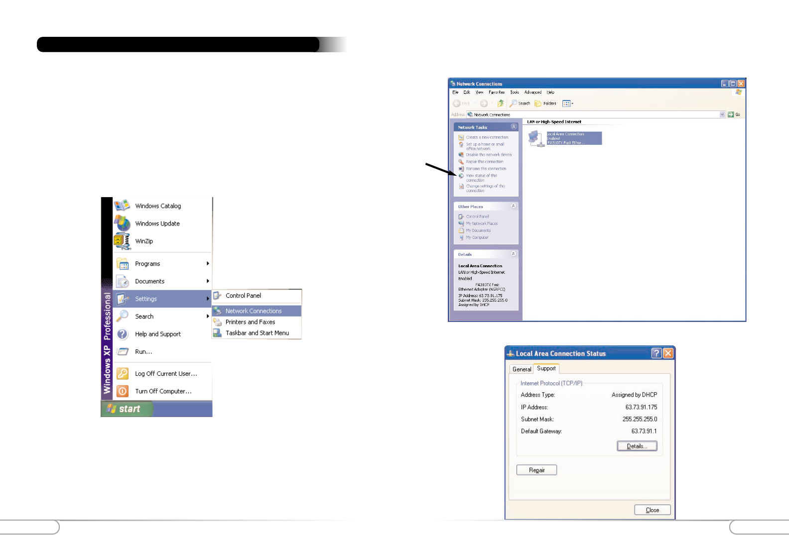
3. The following screen will appear. Click Details to continue.
You will need specific information from your ISP to configure the Wireless Cable/DSL Router.
You can obtain most of this information from your broadband configured PC by following these
4 steps. (Windows XP instructions shown below. For all other Operating Systems please see
Apendix A at the back of this manual)
Note: If you have previously installed Internet Connection Sharing (Ex.
Microsoft ICS) or Proxy Server software (Ex. WINPROXY) you will need to
uninstall them now.
1. Click Start, then Settings and finally Network Connections.
Before you Connect the Wireless Cable/DSL Router 2. On the right hand side of the screen, left click once on you the LAN or high speed
interenet connection that is listed. Then on the left hand side of the screen click
View status of this Connection.
9
Before you Connect the Cable/DSL Router
8Before you Connect the Cable/DSL Router
Your Host/Computer name and Workgroup name (Your ISP may use this information
to verify your identity on their network) (Cable only)
___________________________ ___________________________
Host Name __________________________
(Example: CY57640-A.cospgs1.co.home.com)
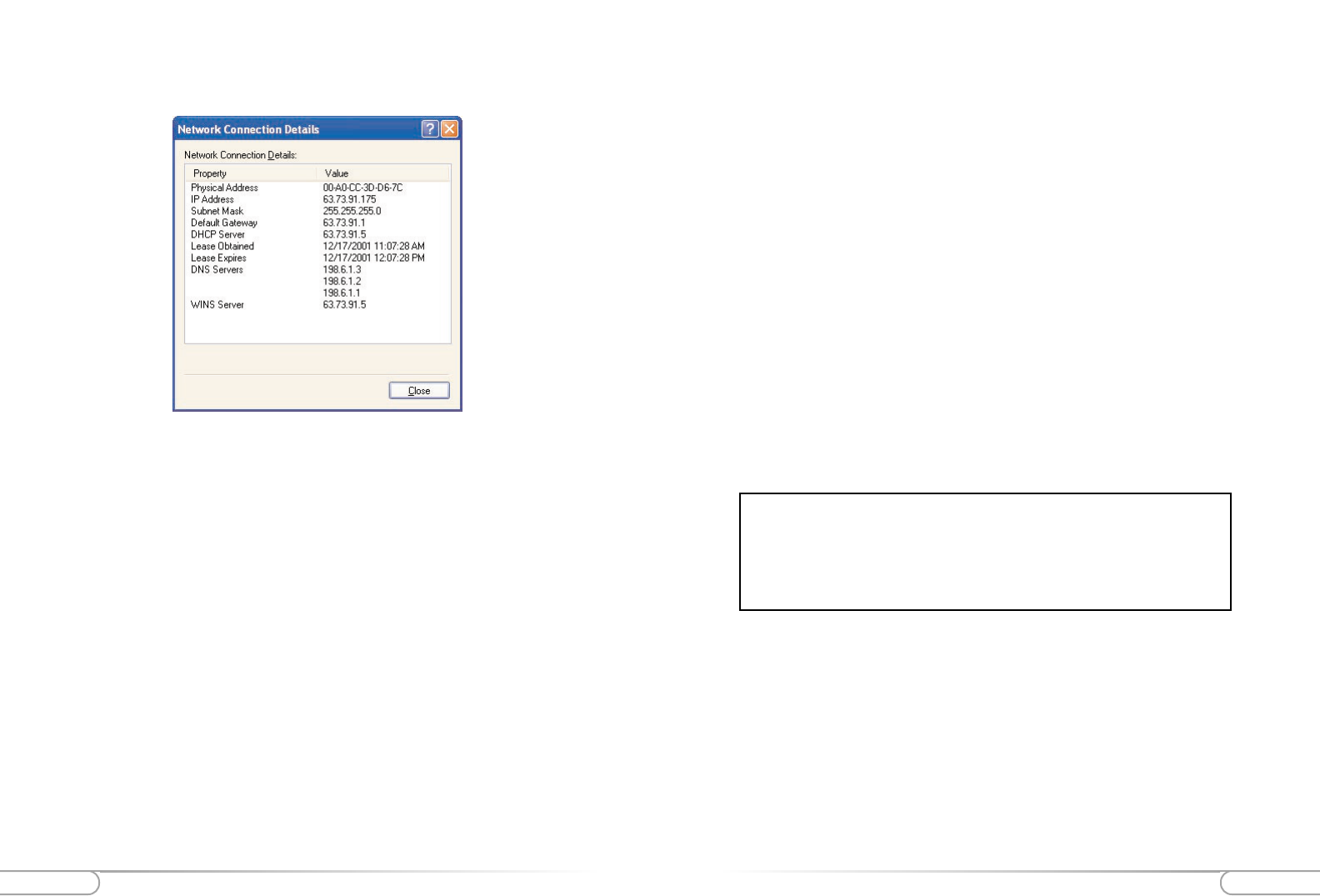
DNS Servers ______.______.______.______
(Example: 24.5.68.33)
Your Secondary DNS server address ______.______.______.______
(Click on the ... button to change the listing)
IP address __________________________
(Example: 24.253.117.45)
Subnet Mask (If assigned) ______.______.______.______
(Example: 255.255.255.0)
For a listing of the information required for the major broadband ISP’s, please
visit the following Website and select your specific ISP. Please make sure that
you have this information available when you configure the Actiontec
Wireless Cable/DSL Router.
HTTP://www.actiontec.com/support/homegateway/index.html
4. The Network Connection Details screen will supply you with neccessary informa-
tion. Write down this information for installation and future reference:
Default Gateway (If assigned) ______.______.______.______
(Example: 24.253.117.1)
Adapter Address _____-_____-_____-_____-_____-_____
(Example: 00-20-78-0F-B8-F0)
Your LOGIN name and PASSWORD (DSL only, provided by your ISP)
___________________________ ___________________________
Mail and Web Server Information
Some broadband providers use single words to direct the connection to their E-mail or
web servers (i.e. web, mail, pop3, www). If your ISP uses single words rather than a
whole internet address (pop.mail.actiontec.com), or IP address (24.55.224.34), then
you will need the full address information to configure your internet browser and/or E-
mail clients.
If this information was not provided during the installation and configuration of your
broadband connection, then you will need to contact your ISP and ask for it.
11
Before you Connect the Cable/DSL Router
10 Before you Connect the Cable/DSL Router
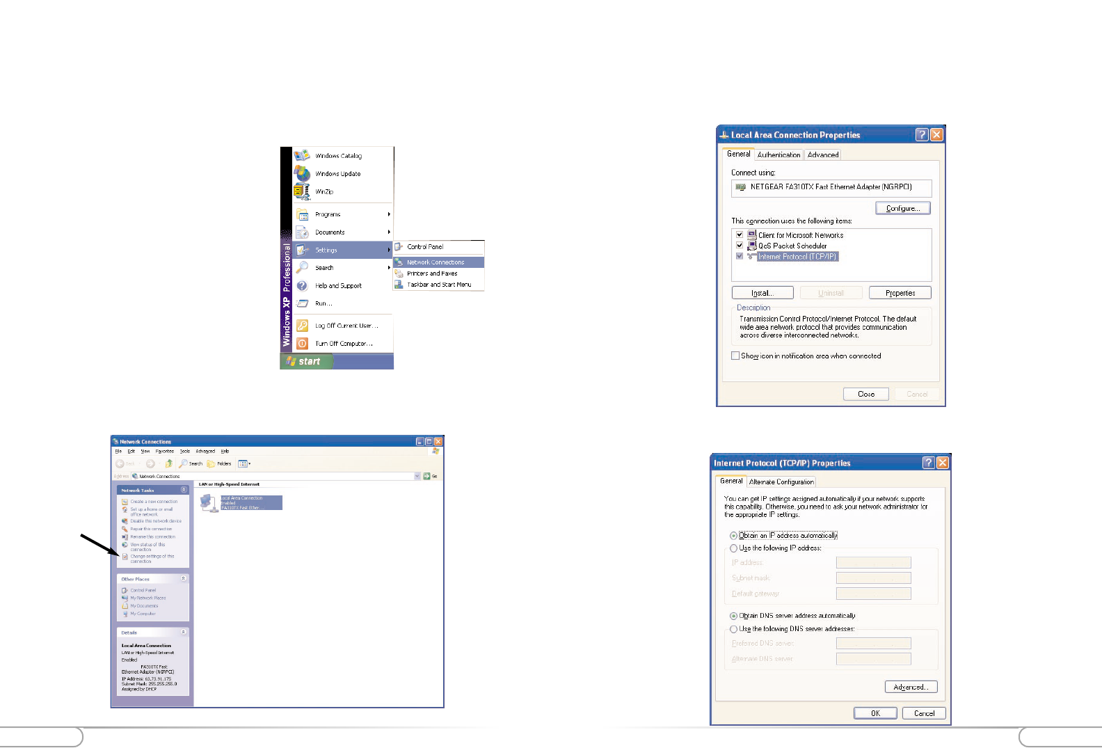
4. Under the General tab select Obtain an IP address automatically, then selct
Obtain DNS server automatically. Click OK.
3. In the Local Area Connection Properties window select TCP/IP and then click
Properties. If there is not a listing for TCP/IP then refer to Appendix B for instal-
lation instructions now. If there are no Ethernet Adapters listed, then refer to the
Ethernet card manufacturer for installation instructions.
Configuring your Computer for Networking
Before configuring the Wireless Cable/DSL Router, a computer must be configured for
standard networking. If you are not running Windows XP, (shown below), then refer to
Appendix A for information on configuring other Windows or MacOS based operating
systems. It may be necessary to have the Windows CD or Ethernet card driver diskette
to complete the configuration.
1. Click Start, then Settings and finally
Network Connections.
2. On the right hand side of the screen, left click once on you the LAN or high speed
interenet connection that is listed. Then on the left hand side of the screen click
Change settings of this Connection.
13
Before you Connect the Wireless Cable/DSL Router
12 Before you Connect the Wireless Cable/DSL Router
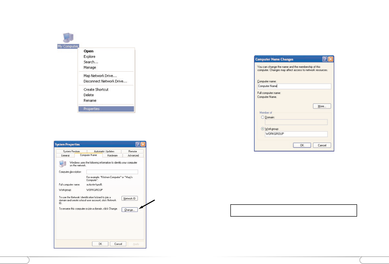
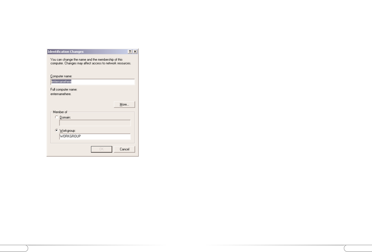
6. The System Properties window will appear. Click the Computer Name tab. The
“Computer Description” field can be anything you want. (A location name or the
main user’s name is generally used) Click Change.
5. On your computer’s desktop right click on My Computer and select Properties
from the given list.
7. Type your chosen computer name in the given field. The “Computer name” field
must have a 15 character limit and must be unique. Make sure that Workgroup is
selected, and then type in the name of your workgroup. The “Workgroup” field
must have the same name on all computers attached to your network. Click OK
when you are finished. You will return to the same screen in step 6, click OK again.
Please restart your computer even if you are not asked to.
8. Once the computer restarts and Windows has finished loading, you will be
prompted for a password. DO NOT PRESS ESCAPE. This is the password that
Windows will use to authenticate your permission to be on the network. The pass-
word you enter now will become your permanent network password. You may also
just press OK or <Enter> and your password will be set to blank.
Note: This password will be required each time you restart Windows.
Repeat steps 1 thru 8 for each PC connected to your network.
Ensure you use the same Workgroup name on each PC.
Before you Connect the Wireless Cable/DSL Router
Before you Connect the Wireless Cable/DSL Router 1514
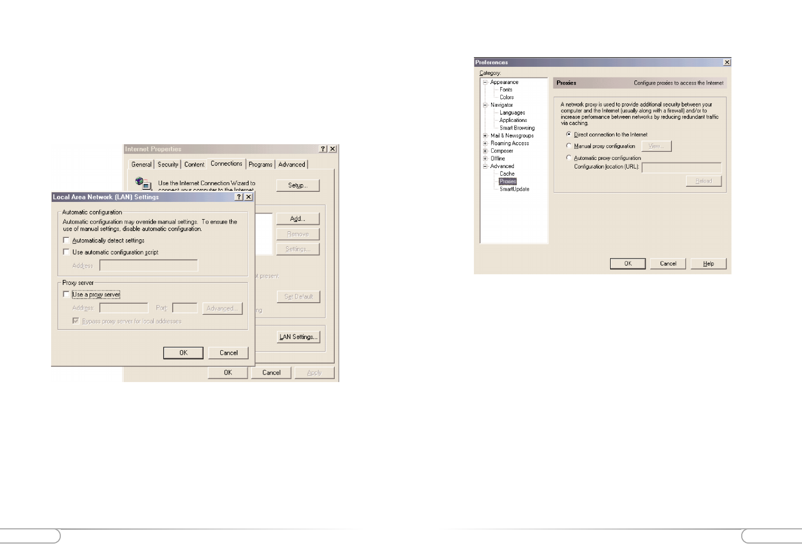
4. Click on Proxies and ensure that Direct connection to the Internet is selected.
5. Click OK to close the Preferences window.
Configuring Your Internet Browser
If “Internet Explorer” is your default browser:
1. Click Start, click Settings, select Control Panel.
2. Double click Internet Options, select the Connections tab.
3. Click LAN Settings. Remove any checks from the 3 boxes and click OK.
4. Click OK to close the Internet Properties window.
5. Close the Control Panel window.
If “Netscape Navigator” is your default browser:
1. Open Netscape Navigator.
2. From the top menu bar select Edit and then click Preferences.
3. Under the Category windows click on the + (plus icon) next to Advanced.
Connecting the Actiontec Wireless Cable/DSL RouterConnecting the Actiontec Wireless Cable/DSL Router 17
16
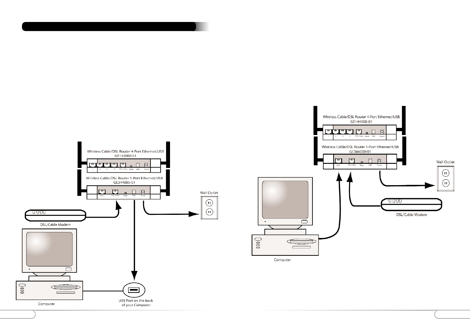
For Ethernet Connection:
1. Please start up your computer.
2. After your computer has started up, locate the blue Ethernet cable marked
"Ethernet cable". Connect the cable to the back of the Actiontec Wireless
Cable/DSL Router and then to your Computer, into the Ethernet slot.
3. Plug the Power Supply into a wall outlet, then plug the other end to the port
labeled “Power”, on the back of the Actiontec Wireless Cable/DSL Router.
The Actiontec Wireless Cable/DSL Router allows you to connect to your computer in
two (wired) ways, by USB cable or Ethernet cable, and wireless. Follow these instruc-
tions for the connection you choose:
For USB Connection:
1. Please start up your computer.
2. After your computer has started up, locate the USB Cable. Connect the square end to the
slot on the ActiontecWireless Cable/DSL Router labeled “USB”. On your PC, connect
the other, rectangular end to the appropriate USB slot.
3. Plug the Power Supply into a wall outlet, then plug the other end to the port
labeled “Power”, on the back of the Actiontec Wireless Cable/DSL Router.
Connecting the Actiontec Wireless Cable/DSL Router
19
Installing the USB Drivers
18 Installing the USB Drivers
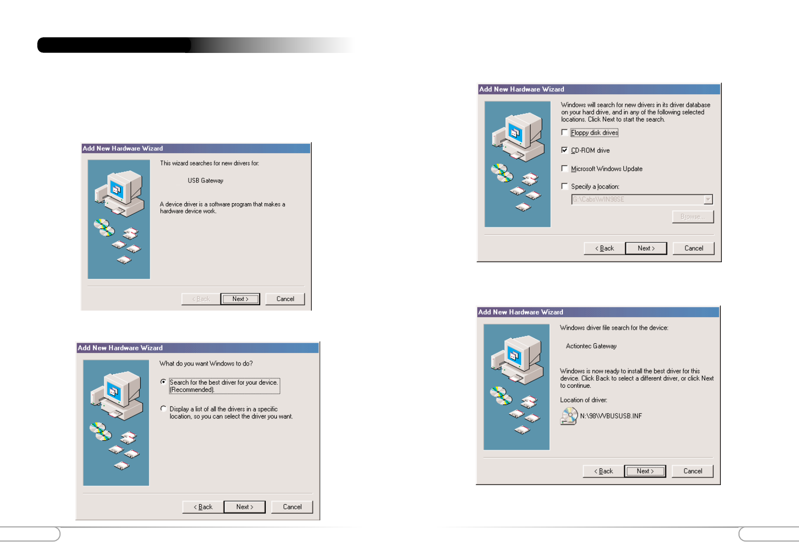
3. Click the box for CD-ROM drive. Before advancing to the next screen, insert the
Actiontec Gateway Installation CD-ROM into the computer’s CD-ROM drive.
Finally, click the Next button.
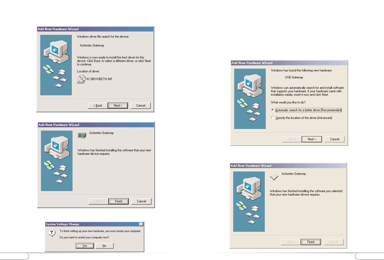
4. Windows will find the appropriate file on the CD-ROM. Click the Next button.
For Windows 98
Note: There are two drivers that will need to be installed, so please follow these instruc-
tions
1. After you have connected the Wireless Cable/DSL Router to your computer, the
Add New Hardware Wizard screen will appear. Click Next to continue.
Installing the USB Drivers
2. Select the option “Search for the best driver for your device (Recommended)” and
then click the Next button.
21
Installing the USB Drivers
20 Installing the USB Drivers
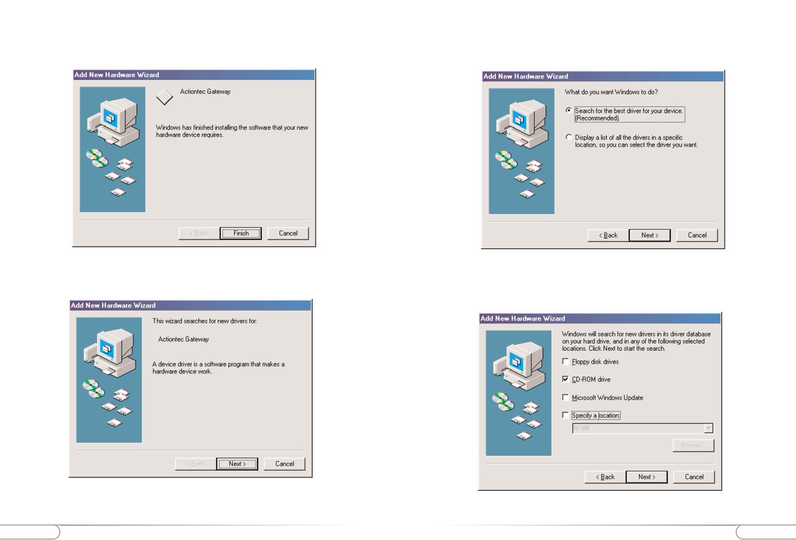
6. Select the option “Search for the best driver for your device (Recommended)” and
then click Next.
7. Click the box for CD-ROM drive. and then click the Next button.
5. Windows will install the first drivers needed for your computer. Click the Finish
button to continue.
6. The following screen will appear. Click Next to install the second driver.
23
Installing the USB Drivers
22 Installing the USB Drivers
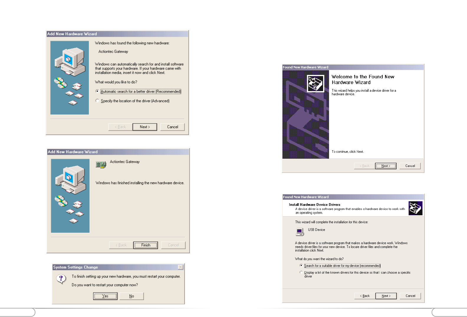
For Windows ME
Note: There are two drivers that will need to be installed, so please follow these instruc-
tions
1. After you have connected the Wireless Cable/DSL Router to your computer, the
Add New Hardware Wizard screen will appear. Make sure “Automatic search...” is
selected and then click Next to continue.
2. Windows will install the first drivers needed for your computer. Click the Finish
button to continue.
8. Windows will find the appropriate file on the CD-ROM. Click the Next button.
9. Click Finish to end the installation process.
10. When the following screen appears, click Yes to restart your computer.
25
Installing the USB Drivers
24 Installing the USB Drivers
For Windows 2000
Note: There are two drivers that will need to be installed, so please follow these instruc-
tions
1. After you have connected the Wireless Cable/DSL Router to your computer, the
Found New Hardware Wizard screen will appear. Click Next to continue.
2. Select the option “Search for a suitable driver for my device (Recommended)” and
then click the Next button.
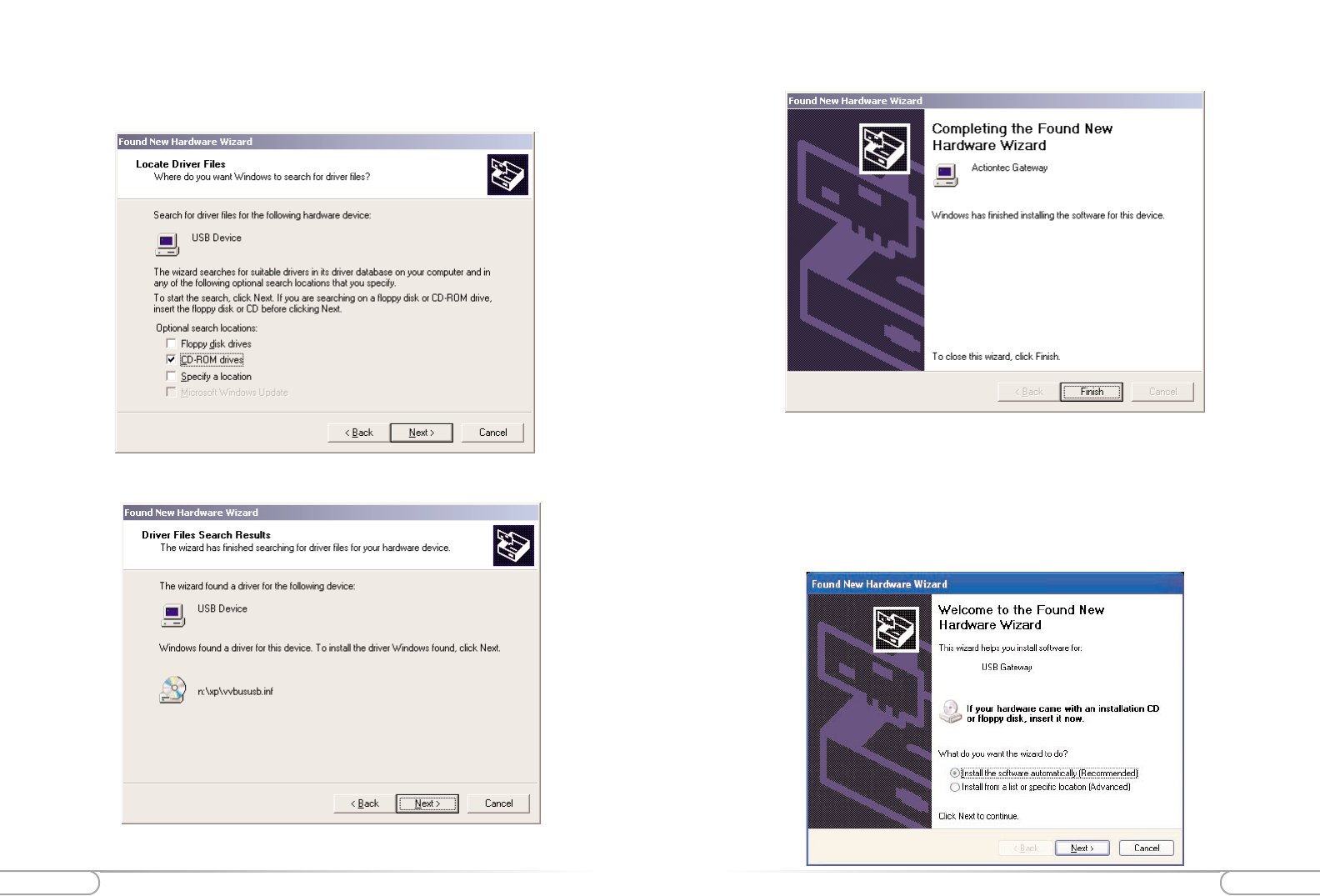
3. Make sure “Automatic search...” is selected and then click Next to continue.
4. Click Finish to end the installation process.
5. When the following screen appears, click Yes to restart your computer.
27
Installing the USB Drivers
26 Installing the USB Drivers
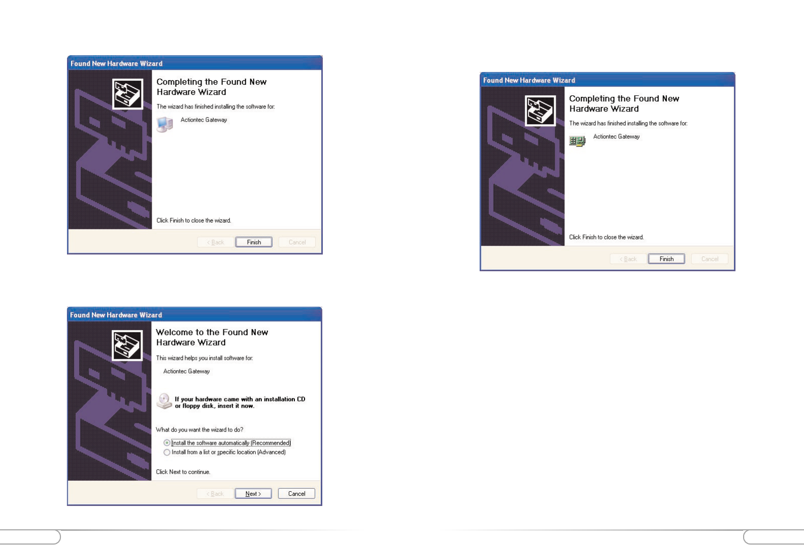
5. Click Finish to end the installation process.
For Windows XP
Note: There are two drivers that will need to be installed, so please follow these instruc-
tions
1. After you have connected the Wireless Cable/DSL Router to your computer, the
Found New Hardware Wizard screen will appear. Make sure “Install software auto-
matically (Recomended)” is selected and then click Next to continue.
3. Click the box for CD-ROM drive. Before advancing to the next screen, insert the
Actiontec Gateway Installation CD-ROM into the computer’s CD-ROM drive.
Finally, click the Next button.
4. Windows will find the appropriate file on the CD-ROM. Click the Next button.
29
Installing the USB Drivers
28 Installing the USB Drivers
4. Windows XP will Install the final set of drivers. Click Next to finish the installa-
tion process.
2. Windows XP will Install the first set of drivers. Click Next to continue.
3. The following screen will appear. Make sure “Install software automatically
(Recomended)” is selected and then click Next to continue.
Configuring the Actiontec Wireless Cable/DSL RouterConfiguring the Actiontec Wireless Cable/DSL Router 31
30
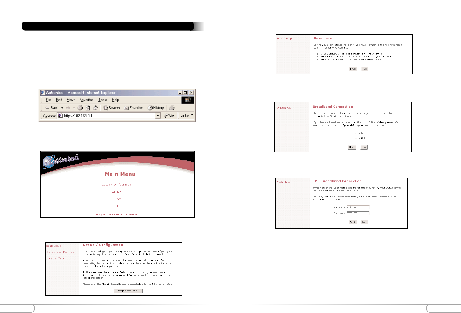
4. Make sure that you have completed the 3 steps listed then click Next.
5. Select either DSL or Cable depending on your broadband service then click Next.
(If your have a T1 Line or Fixed Point Broadband, click Cable.)
6a. If you selected DSL enter your user name and password provided by your ISP.
Click Next.
3. Follow the on-screen instructions and then click Begin Basic Setup.
Basic Setup
Follow the step below to configure your Cable/DSL Router:
1. Open your Internet Web Browser and in the address bar type: http://192.168.0.1
and then press the <Enter> key.
Configuring the Actiontec Wireless Cable/DSL Router
2. When the web page is loaded, the following screen will appear. Click
Setup/Configuration.
Configuring the Actiontec Wireless Cable/DSL Router Configuring the Actiontec Wireless Cable/DSL Router 33
32
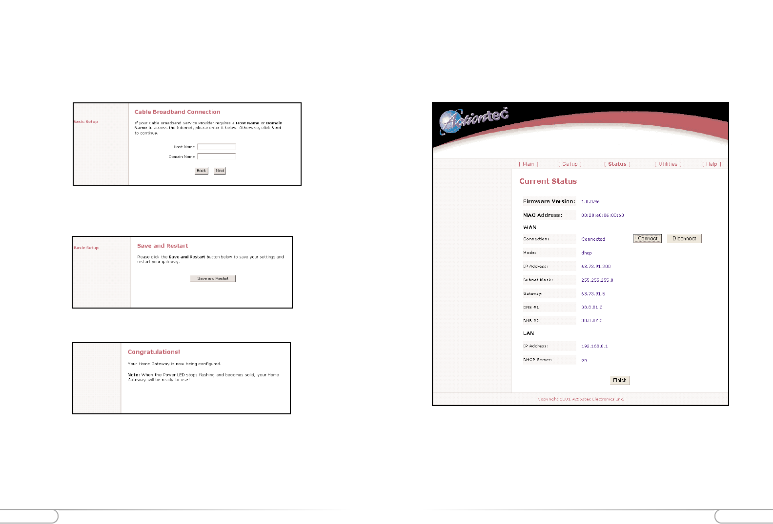
Status Screen
After you have configured your Wireless Cable/DSL Router with the Basic Setup fea-
ture, you can check the status of your Wireless Cable/DSL Router. Click Status an the
main page of the Wireless Cable/DSL Routers’ web based utility. (See second screen
shot, under step 2, on page 18)
Firmware Version:
This will give you the version number of the current firmware.
MAC Address:
This field will display the MAC address of the Wireless Cable/DSL Router. The MAC
address is an identifier that is specific to each device that can connect to any network,
sort of a fingerprint for the Internet. Some ISP’s use this information to validate the PC’s
6b. If you selected Cable and your ISP requires a Host Name or Domain name to
access their network enter it now. Click Next.
Note: If your Cable ISP does not require a host or domain name then leave the
fields blank.
7. Your Actiontec Wireless Cable/DSL Router is now finished with the configuration
process. Click Save and Restart.
8. A congratulations screen will announce the end of the Basic Setup.
The power LED will flash rapidly while the Wireless Cable/DSL Router restarts, before
turning a solid green. The Wireless Cable/DSL Router is now ready and you can begin
surfing the web.
If you receive an error that your browser was unable to connect to the Internet, check
your configuration settings. Please ensure that you entered all the information required
by your ISP.

Configuring the Actiontec Wireless Cable/DSL RouterConfiguring the Actiontec Wireless Cable/DSL Router 35
34
This is the primary Domain Name Server address. This is like a telephone book
of all internet addresses.
DNS #2
This is the secondary Domain Name Server address.
LAN
IP Address
The IP Address of the Wireless Cable/DSL Router as seen by the PC’s within
your LAN.
DHCP Server
On: This means that all of your PC’s will receive their IP address and other con-
figuration data from the Wireless Cable/DSL Router each time they connect.
Off: This means that each machine is configured individually with an IP, subnet
mask, gateway and DNS server information.
identification before it will allow you to access its network.
WAN
Connection:
Connected: A valid connection through the Cable/DSL modem to the Internet
exists.
Connecting...: The Cable/DSL Router is trying to establish a connection with
the ISP.
Disconnected: A valid connection to the Cable/DSL modem exists, but there is
no connection to the Internet.
Off: A valid physical connection to the Cable/DSL modem is not present
Mode:
Static: Static IP Address information for the connection that was entered in the
setup is being used
DHCP: The Wireless Cable/DSL Router is being assigned an IP address and
being sent other connection information each time the connection to the ISP is
renewed
PPPoE: The connection is being made through Point to Point Protocol. This is
usually the case for DSL broadband.
IP Address
The IP address currently assigned and being used by the Wireless Cable/DSL
Router to connect to the ISP
Subnet Mask
The subnet mask being used is normally 255.255.255.0 (Class C IP Address)
Gateway
This is the IP address that the Wireless Cable/DSL Router uses to send all
requests to the Internet.
DNS #1
Advanced Configuration of the Wireless Cable/DSL RouterAdvanced Configuration of the Wireless Cable/DSL Router 37
36
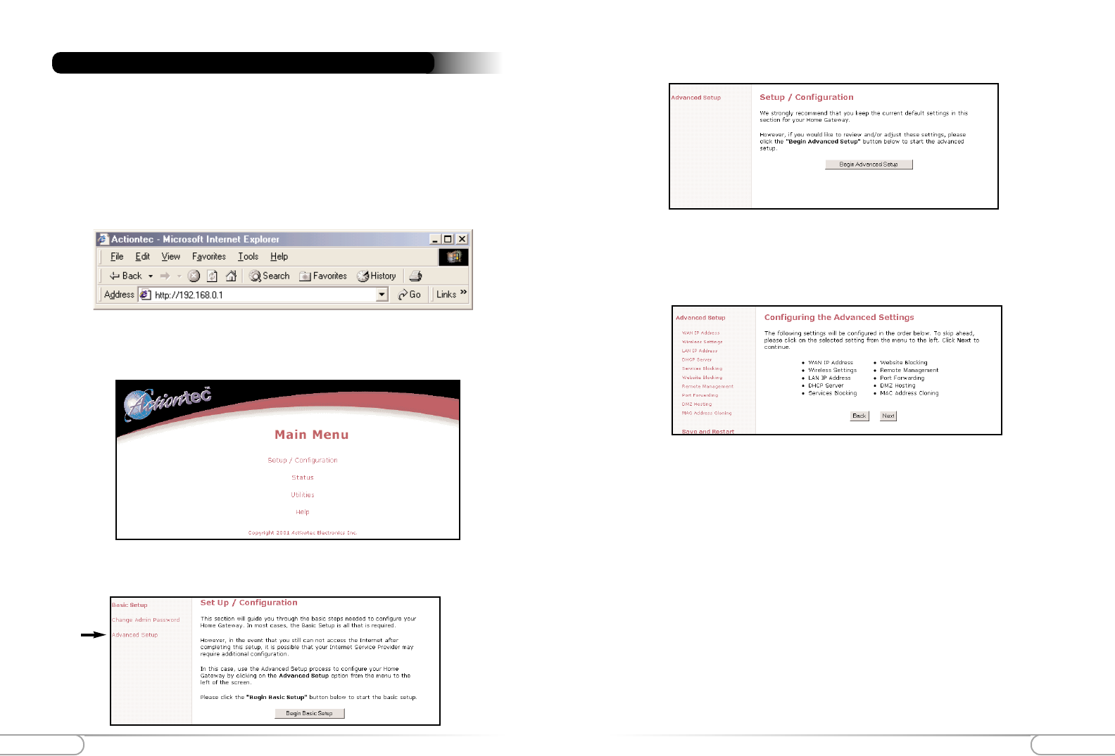
4. Click on Begin Advanced Setup.
5. You will see the following screen showing all the options available in Advanced
Setup. If you want to check all the settings, or are unsure of which setting you want
to modify, select Next. If you want to modify a specific configuration, simply click
on its name in the left menu bar.
Note: You may click Save and Restart on the bottom left hand side of the screen
when you have finished configuring any one or more of the advance settings.
3. Follow the on-screen instructions and then click Advanced Setup.
The Advanced Setup section allows advanced users to configure such features as the
wireless settings. The following sections explain each feature you can configure in the
advanced setup section.
1. Open your Internet Web Browser and in the address bar type: http://192.168.0.1
and then press the <Enter> key.
Advanced Configuration of the Wireless Cable/DSL Router
2. When the web page is loaded, the following screen will appear. Click
Setup/Configuration.
Advanced Configuration of the Wireless Cable/DSL RouterAdvanced Configuration of the Wireless Cable/DSL Router 39
38
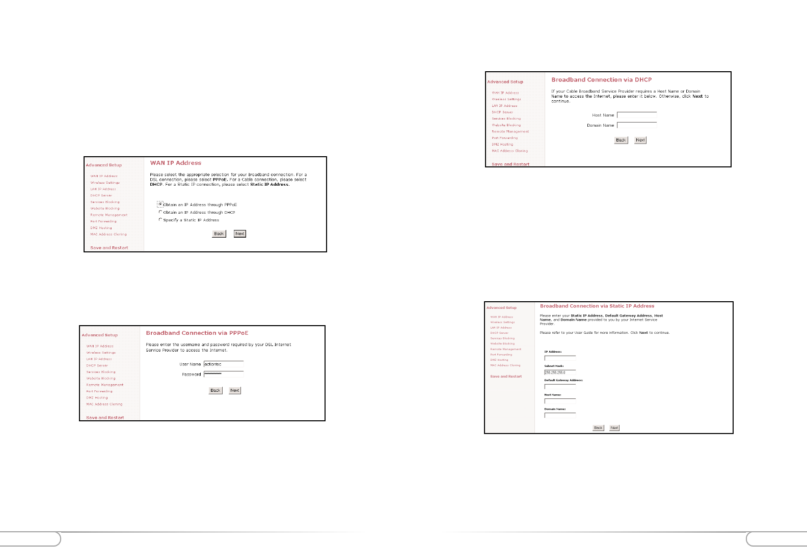
Note: For the Host Name and Domain Name you may also find this informa-
tion from your PC which was originally connected to the cable modem. Please
see the Before you Begin section on pages 6-7. If your cable modem ISP does not
require these settings, then you may leave them blank.
Specify a Static IP Address
This setting is used if you have been assigned a static (Specific) IP Address by your ISP.
You will need to enter the IP Address and Default Gateway provided by your ISP. You
may also need to enter your Host Name and Domain Name if required.
with their host name and/or domain name. Please check with your ISP for what host
name and domain name you have to use in the following fields.
IP Address: IP Address of your Wireless Cable/DSL Router as seen by external
users on the Internet.
Subnet Mask: This will be provided by your ISP.
Default Gateway: This will be provided by your ISP.
Wan IP Address
This screen allows you to manually set up your Wireless Cable/DSL Router. The fol-
lowing are three methods by which your ISP will assign an IP Address to your Wireless
Cable/DSL Router.
Note: Some DSL providers use PPPoE to establish communication with an end
user, while others use static IP. Cable modem providers and other broadband
Internet access such as fixed point wireless may use either DHCP or Static IP
address. If you are unsure, please check with your ISP.
Obtain and IP Address through PPPoE
This setting is used for DSL connections and it allows the modem to use the Point-to-
Point over Ethernet (PPPoE) protocol. If you already entered the user name and pass-
word in the Basic Setup, then it should be displayed now. Click Next to continue.
User Name: User name given to you by your DSL provider to access the Internet.
Password: Password given to you by your DSL provider to access the Internet.
Obtain an IP through DHCP
This setting is used for Cable modem configurations that do not have a Static IP
assigned by the ISP. This allows the modem to query the ISP and receive an IP address
and routing information. Some cable modem providers need to authenticate the users
Advanced Configuration of the Wireless Cable/DSL RouterAdvanced Configuration of the Wireless Cable/DSL Router 41
40
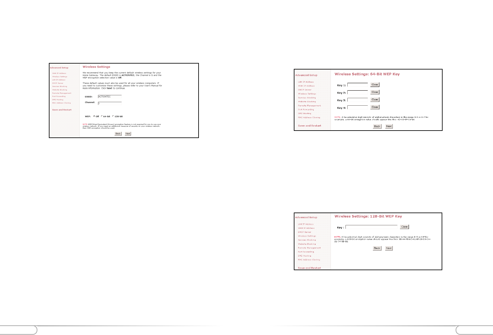
128-bit Wireless Equivalent Privacy (WEP)
The 128-bit encryption requires a single field of 13 hexadecimal pairs (A hexadecimal
digit consists of alphanumeric characters in the range 0-9 or A-F). An example of 128-
bit encryption would be: 3D-44-FE-6C-A1-EF-2E-D3-C4-21-74-5D-B1.If you do
create this key, make sure you enter it in your Wireless PC Card exactly as you have it
in the Wireless Cable/DSL Router.
Note: Do not use the 128-BIT WEP Key if your PC Card does not support it.
64-bit Wireless Equivalent Privacy (WEP)
The 64-bit eencryption requires 4 fields of 5 hexadecimal pairs. (A hexadecimal digit
consists of alphanumeric characters in the range of 0-9 or A-F). An example of 64-bit
encryption would be: 4E-23-3D-68-72. If you do create this key, make sure you enter
it in your Wireless PC Card exactly as you have it in the Wireless Cable/DSL Router.
Wireless Settings
The Wireless Settings screen allows you to take advantage of the Wireless Cable/DSL
Router’s wireless capabilities.
ESSID
(Default value set to ACTIONTEC) This is an arbitrary network name that you assign
to your wireless network. You may use alphanumeric characters (i.e.: A-Z, a-z, 0-9). It
is important that you set your Wireless PC Cards to the same ESSID value. (For the
Actiontec 802.11b Wireless PC Card the ESSID value should be the same as the SSID
value) This will enable the Wireless PC Cards to communicate with your Wireless
Cable/DSL Router.
Channel
This assigns the frequency band in which the Wireless Cable/DSL Router can commu-
nicate at. In the United States you may use channels 1-11. (Default value set to 1)
Wireless Equivalent Privacy (WEP)
This is an encryption method used in the 802.11b standard, to ensure data security over
your wireless network. The Actiontec Wireless Cable/DSL Router offers three levels of
encryption.If you do not require the encryption, it is recommended that you keep this
feature disabled (off). It is not required for wireless operation, and can reduce network
performance since each piece of data must be encrypted and decrypted.
Advanced Configuration of the Wireless Cable/DSL RouterAdvanced Configuration of the Wireless Cable/DSL Router 43
42
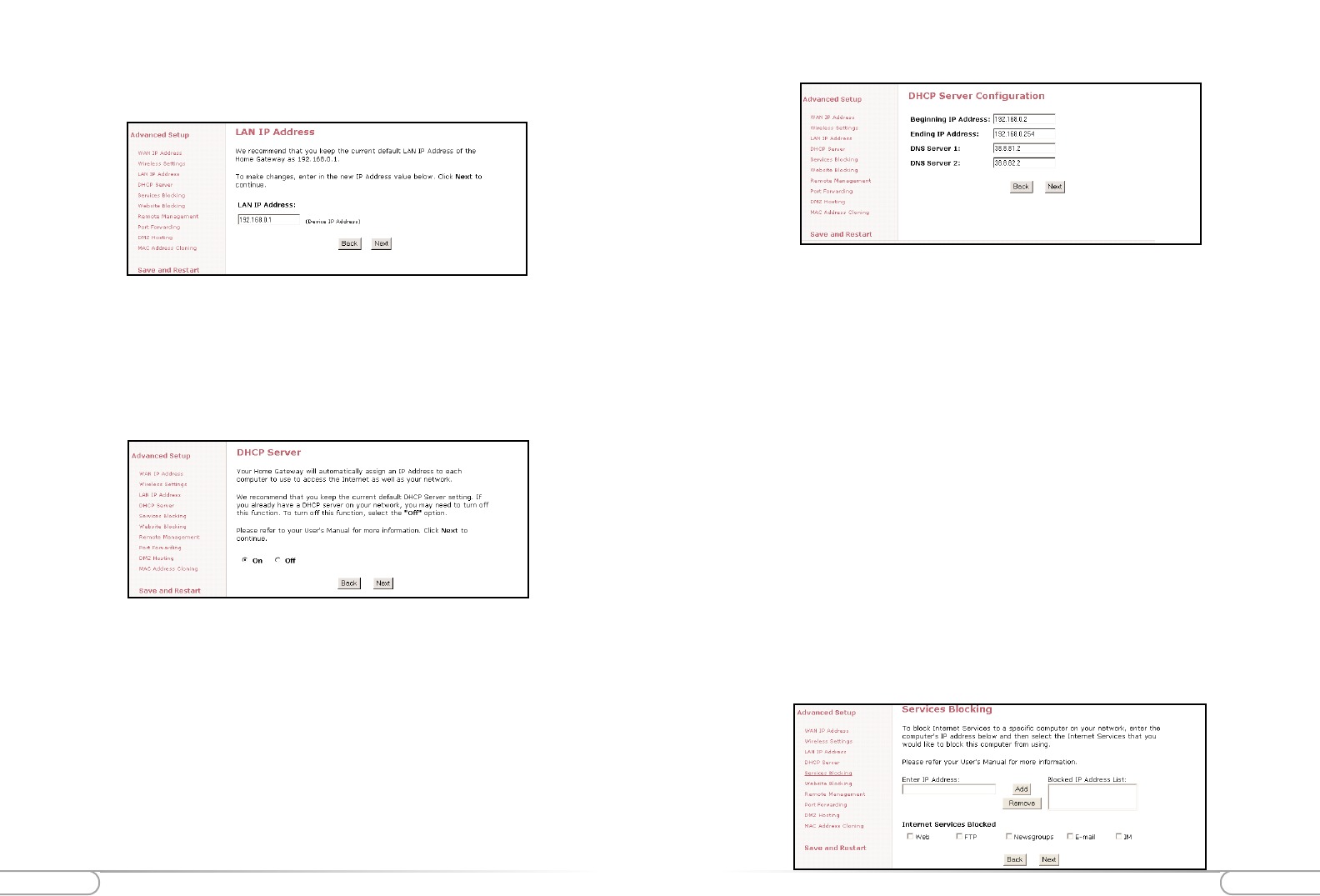
DHCP Server Configuration
Beginning IP Address
Enter the IP Address for the DHCP Server to start when assigning IP Address. It is rec-
ommended that you keep the default settings of 192.168.0.2
Ending IP Address
Enter the IP Address for the DHCP Server to end when assigning IP Address. It is rec-
ommended that you keep the default settings of 192.168.0.254
DNS Server 1
Enter the primary DNS provided by your ISP. You may keep the default settings if you
wish.
DNS Server 2
Enter the secondary DNS provided by your ISP. You may keep the default settings if you
wish.
Services Blocking
This screen enables you to create Client or Internet privileges for certain computers’ on
your network. If you do not specify any settings then all of the computers on your net-
work will have full priviledges.
LAN IP Address
This is the IP Address of the Wireless Cable/DSL Router as seen on the internal LAN.
It is recommended that you keep the default settings, but if you need to change them
then be sure to verify the DHCP Server range is within the same subnet.
DHCP Server
Your Wireless Cable/DSL Router has a built-in Dynamic Host Configuration Protocol
(DHCP) Server that can automatically assign an IP Address to each computer on your
network.
It is highly recommended that you keep the default DHCP Server settings. If you wish
to disable your DHCP Server, select Off. You will need to ensure that the IP Address of
your computers are in the same subnet as that of the Wireless Cable/DSL Router. To be
in the same subnet, the IP address must begin with the same numbers for the first 3
fields. (Example: 192.168.0.1 would mean your IP address would have to be
192.168.0.x, with x being 2 - 254.)
Advanced Configuration of the Wireless Cable/DSL RouterAdvanced Configuration of the Wireless Cable/DSL Router 45
44
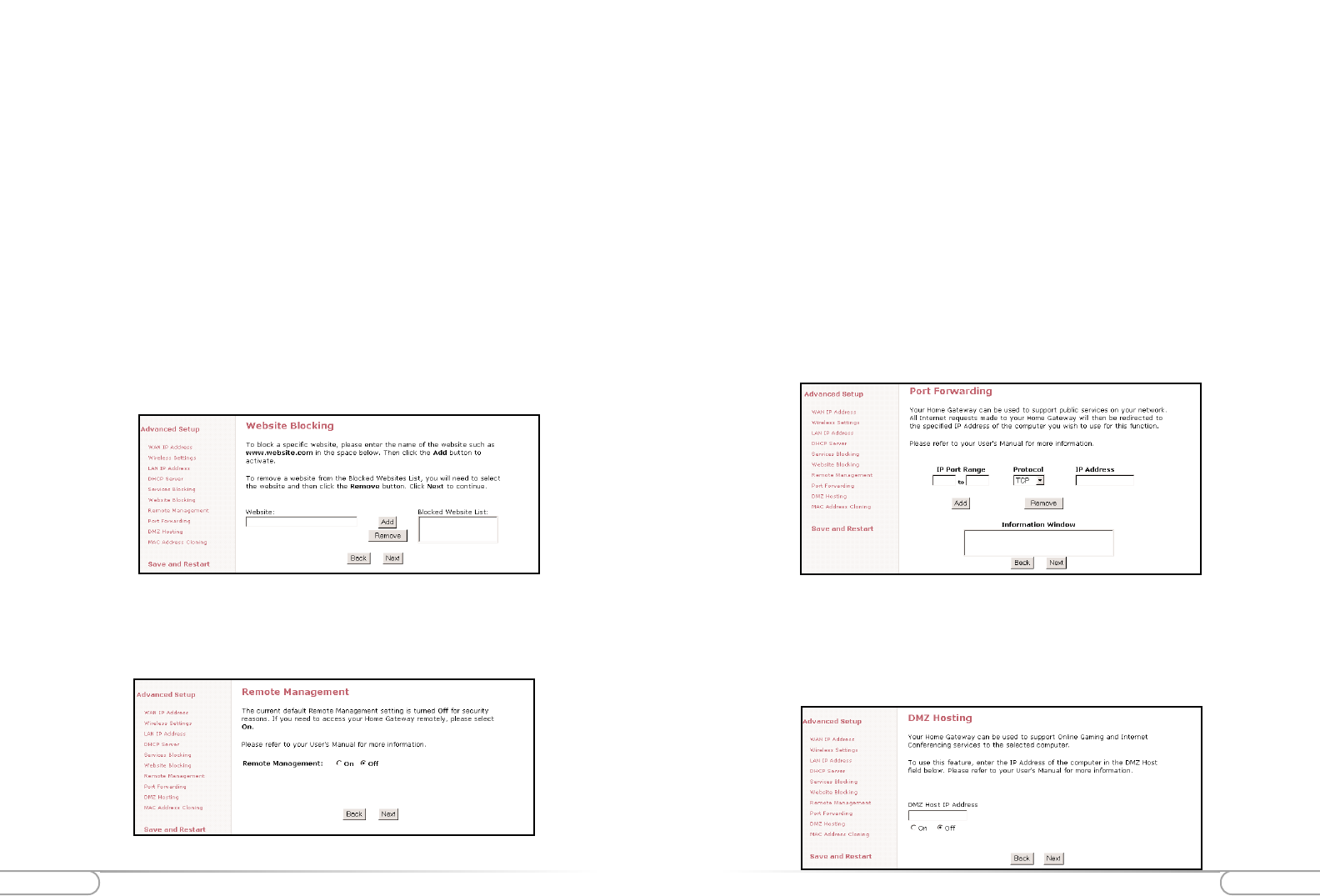
DMZ Hosting
DMZ hosting is used to support online gaming and Internet confrencing services. These
programs usually require multiple ports to be open on the Wireless Cable/DSL Router,
making the rest of your network vulnerable to the Internet. DMZ hosting will symbol-
ically place the designated computer (By IP address) outside of the Wireless Cable/DSL
1. Find out the WAN IP Address of your Wireless Cable/DSL Router from the Status
page.
2. From a location outside of your network, open your Internet browser. In the
address field type your WAN IP address (i.e. http//192.123.4.1) and press <Enter>.
This will bring up your Wireless Cable/DSL Router menu or password prompt (if
a password has been set.
Port Forwarding
Because the Wireless Cable/DSL Router is acting as a firewall for your network, some
programs may not be able to communicate over the Internet without some additional
configuration. This feature is useful if you want to host a webserver or ftp server on your
private LAN. You will need to open each port that your programs need and specify to a
specific IP (Computer). It is recommended that if you need to open more than 10 ports
at once to use DMZ hosting instead. For a listing of commonly used programs and their
port numbers refer to Appendix C or the Actiontec web site.
Remote Management
The Remote Management feature allows users to access the Wireless Cable/DSL Router
through the Internet. It is recommended that you do not alter the Remote Management
properties. For security reasons, it is disabled by default.
To access the Wireless Cable/DSL Router from the Internet:
1. Enter the clients IP address in the given field.
2. At the bottom of the page select the Internet services that you want blocked for that
particular client PC.
3. Click Add to place your choice in the “Blocked IP Address List”.
4. If you would like to remove any of the blocked services, click on the IP Address in
the “Blocked IP Address List” and click Remove.
Website Blocking
This feature enables you to block specific websites. Simply enter the name of the web-
site into the appropriate field and click Add. When the user tries to access a blocked
website, the website will not be displayed. If you would like to remove a blocked web-
site, click on it in the “Blocked Website List” and then click Remove.
Note: Once a blocked website is selected, no user on the network will be able to
access that site
UtilitiesAdvanced Configuration of the Wireless Cable/DSL Router 47
46
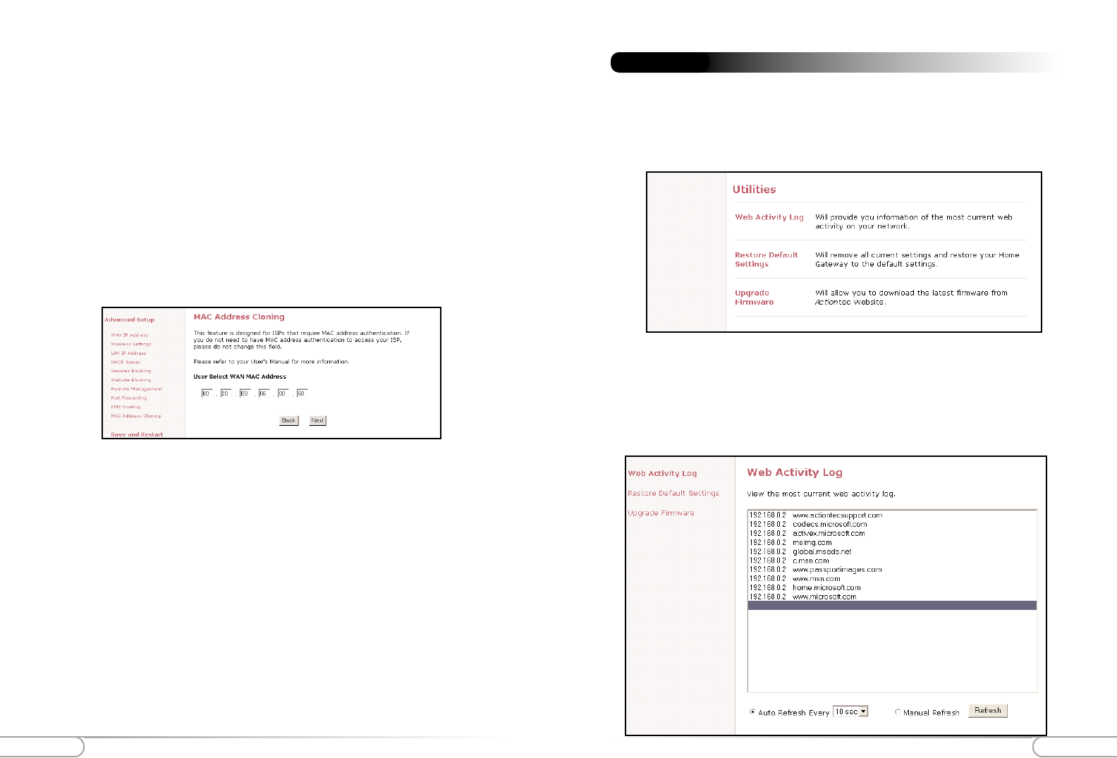
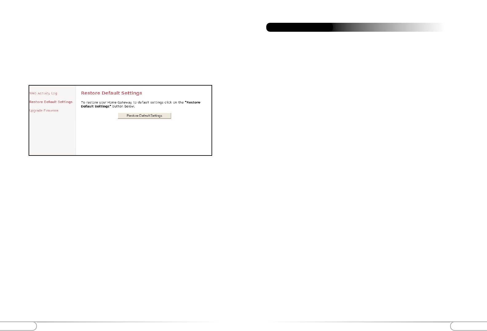
On the main screen of your Wireless Cable/DSL Router you will find a section called
Utilities. This section allows you to view your Web Activity Log, Restore Default
Settings and Upgrade your Firmware. Follow the steps in each section below to use these
features:
Utilities
Web Activity Log
This allows you to view the websites that each computer connected to your Wireless
Cable/DSL Router, has viewed.
1. Click on Utilities
2. Click on Web Activity Log.
Router. You will be unable to access your network resources while in the DMZ. It is rec-
ommended to place the computer in the DMZ mode only as long as it is necessary. You
will also be unable to access your network resources.
WARNING: This computer will be vulnerable to outside hackers while in the
DMZ mode.
MAC Address Cloning
The MAC address is an identifier that is specific to each device that connects to any
network, simular to a fingerprint for the Internet. Some ISP’s require this information
to validate a computers permission to be on the network. If your ISP requires this infor-
mation, you will need to determine the MAC address of the computer that was origi-
nally configured for your service (Appendix D has instructions to determine the MAC
address).
TroubleshootingUtilities 49
48
There is a LAN connection failure to the Wireless Cable/DSL Router.
Make sure that the Wireless Cable/DSL Router is properly installed, the LAN con-
nections are correct and the power is on. Next, confirm that your PC and the
Wireless Access Point and Gateway are on the same network segment. If you are
not sure, let the PC get the IP address automatically by initiating the DHCP func-
tion. Then, verify that your PC is using an IP address within the default range of
192.168.1.2 to 198.168.1.XXX. If your PC is not using an IP address within the
range then it will not be compatible with the Gateway. Finally, the Subnet Mask
must be set to 255.255.255.0 to match the Gateway. In the Gateway you can check
this by clicking on Status on the Wireless Cable/DSL Routers start page.
I am unable to browse through the Wireless Cable/DSL Router.
First, make sure that both ends of the power adapter and network cables are prop-
erly connected and the status LEDs on the front panel are infact working proper-
ly. Then, if you are using Windows 95 or 98, check your computer’s TCP/IP setup:
On your desktop click Start, then select Run, type winpcfg in the given box and
then hit Enter. Your computer should have an IP address of 192.168.XXX (the
“XXX” value could be from 2 to 254.) Also the Subnet Mask should be
255.255.255.0. Then, check the Wireless Cable/DSL Router settings to verify that
they are the same as your computer. You can do this by clicking on Status on the
Wireless Cable/DSL Routers start page.
I get a time out error when I enter a URL or IP Address,
First, verify that all your computers are working properly. Then make sure that all
your IP settings are correct. If you are still having trouble make sure that the
Wireless Cable/DSL Router is on and connected properly. If it is connected prop-
erly open up your web browser and access the Wireless Cable/DSL Router’s start
page. Verify that the Wireless Cable/DSL Router settings are correct by clicking on
Status. If this too is properly configured then check your Cable or DSL modem by
attempting to connect to the Internet.
I am unable to get an IP Address from my Cable or DSL Modem.
First, make sure that your Wireless Cable/DSL Router is properly connected to
your computer and is plugged in. Then, shut off your Cable or DSL modem and
wait a few seconds. Turn it back on, wait for it to go through its self test and then
check for the IP Address. Then, verify that your modem is DHCP compatible. Go
to the Wireless Cable/DSL Router’s web based utility and make sure you entered
the user name and password for either your DSL or Cable modem.
Troubleshooting
Restore Default Settings
This allows you to restore your Wireless Cable/DSL Router to its original default set-
tings.
1. Click on Utilities
2. Click on Restore Default Settings.
3. Click the Restore Default Settings button.
Upgrading your Firmware
From time to time, Actiontec will post firmware upgrades to enhance your Wireless
Cable/DSL Router’s usability. To upgrade your Wireless Cable/DSL Router’s
firmware:
1. Click on Utilities
2. Click on Upgrade Firmware. Follow the onscreen instructions.
3. After downloading the upgrade files and extracting it to a folder on your hard drive,
double click on upgrade.exe.
4. Input the IP address of your Wireless Cable/DSL Router (typically it will be
192.168.0.1), and click Start. The upgrade progress will begin.
5. After the Upgrade is complete, unplug the power from the Wireless Cable/DSL
Router then re-plug it.
6. Wait for the power LED to stop blinking and become a steady green.
7. You will need to reconfigure your Wireless Cable/DSL Router settings.

GlossaryGlossary 51
50
ESSID (Extended Service Set Identifier)
You must have the same ESSID entered into the gateway and each of its wireless clients.
The ESSID is a unique identifier for your wireless network.
Ethernet
Ethernet networks are connected by cables and hubs, and move data around. This is a
standard for computer networks.
Firewall
A Firewall prevents anyone outside of your network from accessing your computer and
possibly damaging or viewing your files.
Gateway
A central device that manages all the data traffic of your network, as well as to the
Internet.
IP Address (Internet Protocol)
An IP address consists of a series of four numbers separated by periods, that identifies a
unique Internet computer host.
ISP Gateway Address (see ISP for definition)
The ISP Gateway Address is an IP address for the Internet router. This address is only
required when using a cable or DSL modem.
ISP (Internet Service Provider)
An ISP is a business that allows individuals or businesses to connect to the Internet.
LAN (Local Area Network)
A LAN is a group of computers and devices connected together in a relatively small
area (such as a house or an office). Your home network is considered a LAN.
MAC Address (Media Access Control)
A MAC address is the hardware address of a device connected to a network.
NAT (Network Address Translation)
Access Point
An access point is a device that allows wireless clients to connect to other wireless clients
and it acts as a bridge between wireless clients and a wired network’ like Ethernet.
Wireless clients can be moved anywhere within the coverage area of the access point and
still connect with eachother. If connected to an Ethernet network, the access point mon-
itors Ethernet traffic and forwards appropriate Ethernet messages to the wireless net-
work, while also monitoring wireless client radio traffic and forwarding wireless client
messages to the Ethernet LAN.
Channel
The home wireless gateway allows you to choose different radio channels in the wireless
spectrum. A gateway operates within the 2.4 GHz spectrum and a channel is within a
FCC specified range, simular to any radio channel.
Client
A client is the desktop or mobile PC that is connected to your network.
DHCP (Dynamic Host Configuration Protocol)
This automatically assigns an IP address for every computer on your network.
DNS Server Address (Domain Name System)
DNS allows Internet host computers to have a domain name and one or more IP
addresses. A DNS server keeps a database of host computers and their respective domain
names and IP addresses, so that when a user enters a domain name into the internet
browser, the user is sent to the proper IP address. The DNS server address used by the
computers on your home network is the location of the DNS server your ISP has
assigned.
DSL Modem (Digital Subscriber Line)
A DSL modem uses your existing phone lines to transmit data at high speeds.
Encryption
This provides wireless data transmissions with a level of security.
Glossary

Glossary Specifications 53
52
Model Number: GE344000-01 Wireless Cable/DSL Router 1-Port
GE144000-01 Wireless Cable/DSL Router 4-Port
Standards: IEEE 802.3 (10BaseT), IEEE 802.3u (100BaseTX), IEEE
802.11b (Wireless)
Protocol: CSMA/CD
WAN: One 10Base-T RJ-45 Port for Cable/DSL Modem
LAN: (GE144000-01) Four 10/100 RJ-45 Switched Ports, One USB
port
(GE344000-01) One 10/10100 RJ-45One Shared Uplink
Port, One USB port
Expansion: One PCMCIA expansion slot
Speed: WAN - 10Mbps, LAN Ethernet - 10/100Mbps Wireless (See
Below)
Cabling Type: 10BaseT: UTP/STP Category 3 or 5
100BaseTX: UTP/STP Category 5
Button: Reset
Operation Range:
(Wireless)
Indoors: Up to 30M (100 ft.) @ 11 Mbps
Up to 50M (165 ft.) @ 5.5 Mbps
Up to 70M (230 ft.) @ 2 Mbps
Up to 91M (300 ft.) @ 1 Mbps
Outdoors: Up to 152M (500 ft.) @ 11 Mbps
Up to 270M (885 ft.) @ 5.5 Mbps
Up to 396 (1300 ft.) @ 2 Mbps
Up to 457M (1500 ft.) @ 1 Mbps
Topology: Star (Ethernet)
LED Indicators: 1-Port Router: Power, Internet, Wireless, LAN, USB
4-Port Router: Power, Internet, Wireless, Ethernet Network
WAN: Link
LAN: Link/Activity
Specifications
This process allows all of the computers on your home network to use one IP address.
This will enable access to the Internet from any computer on your home network with-
out having to purchase more IP addresses from your ISP.
PC Card
This is an ethernet card that connects to the PCMCIA slot on your lap top or desktop
PC. This enables the computer to communicate with with the Wireless Cable/DSL
Router.
PPPoE (Point-to-Point Protocol over Ethernet.)
Point-to-Point Protocol is a method of secure data transmission.
Subnet Mask
A subnet mask is a set of four numbers configured like an IP address. It is used to cre-
ate IP address numbers used only within a particular network.
TCP/IP (Transmission Control Protocol/Internet Protocol)
This is the standard protocol for data transmission over the Internet.
WAN (Wide Area Network)
A network that connects computers located in separate areas, (i.e., different buildings,
cities, countries). The Internet is a wide area network.
WECA (Wireless Ethernet Compatibility Alliance)
An industry group that certifies cross-vender interoperability and compatibility of IEEE
802.11b wireless networking products and to promote that standard for enterprise,
small business, and home environments.
WLAN (Wireless Local Area Network)
This is a group of computers and other devices connected wirelessly in a small area. A
wireless network is referred to as LAN or WLAN.
Appendix AEnvironmental 55
54
Configuring TCP/IP For Windows NT 4.0
Please make sure you have your Windows NT Workstation 4.0 installation disks or CD-
ROM handy before beginning. Windows NT Workstation 4.0 may need to copy some
driver information during the configuration process. If your Ethernet card was supplied
with a driver diskette, be sure to have that available as well.
Note: As with all software, you should consult your users manual or the help files
for detailed information. Actiontec provides the information that follows as a
guideline only.
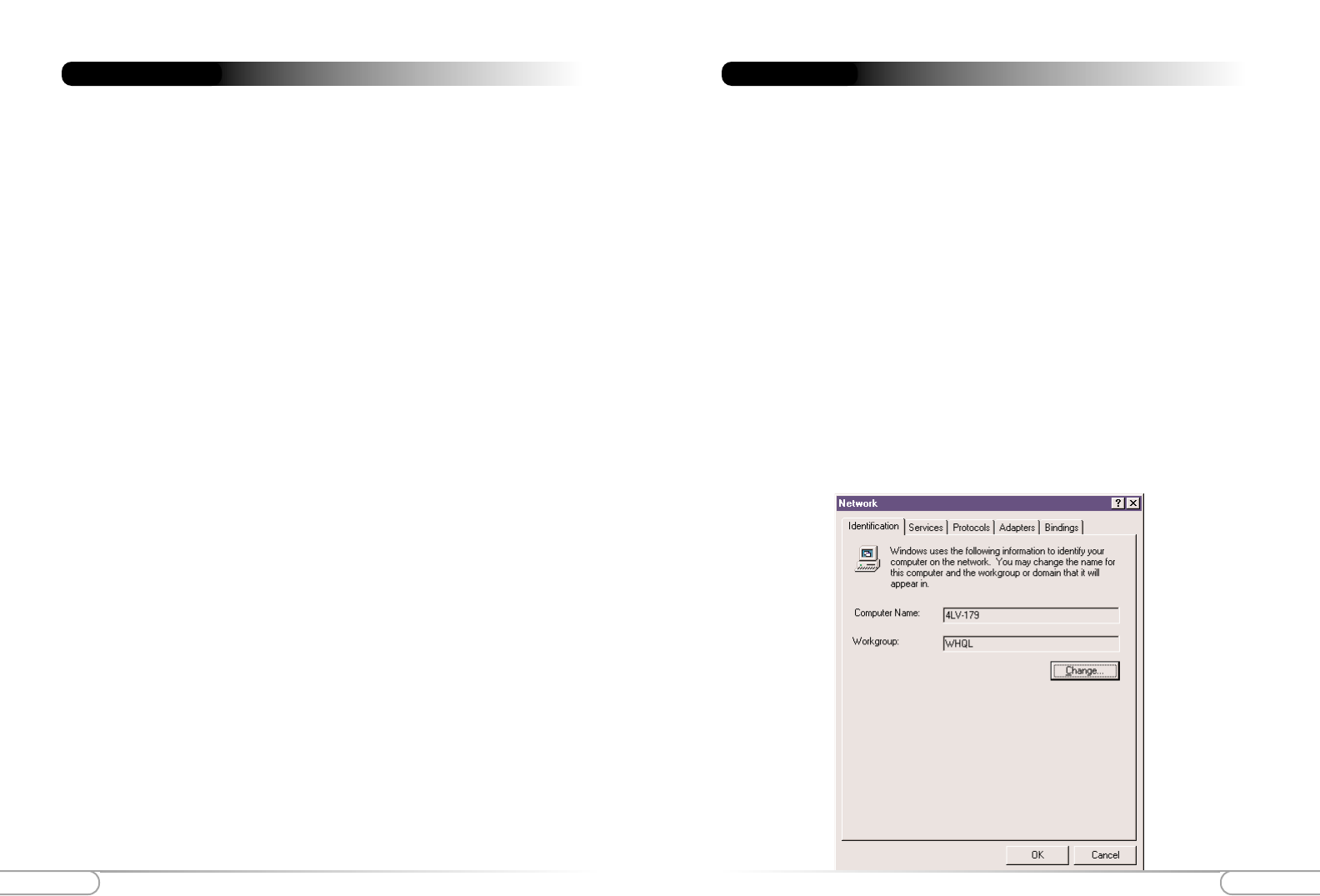
Network, Username, Computer Name Identification
To configure your NT Workstation v 4.0 click Start, go to Settings and then to Control
Panel. In Control Panel, double-click the Network icon. In the Network dialog box,
click the Identification tab and enter a Computer Name if needed and a Work Group.
Note: Do not change both Computer name and Workgroup at the same time.
Change one first and then restart. Then change the other and restart a second
time.
Appendix A
Power Input: External, 5V DC, 2.5 A
Certifications: FCC Class B, FCC Class C, CE Mark Commercial, UL, Wi-Fi
Operating Temperature: 0º C to 40º C (32ºF to 104ºF)
Storage Temperature: -20ºC to 70ºC (-4ºF to 158ºF)
Operating Humidity: 10% to 85% Non-Condensing
Storage Humidity: 5% to 90%, Non-Condensing
Environmental
Appendix AAppendix A 57
56
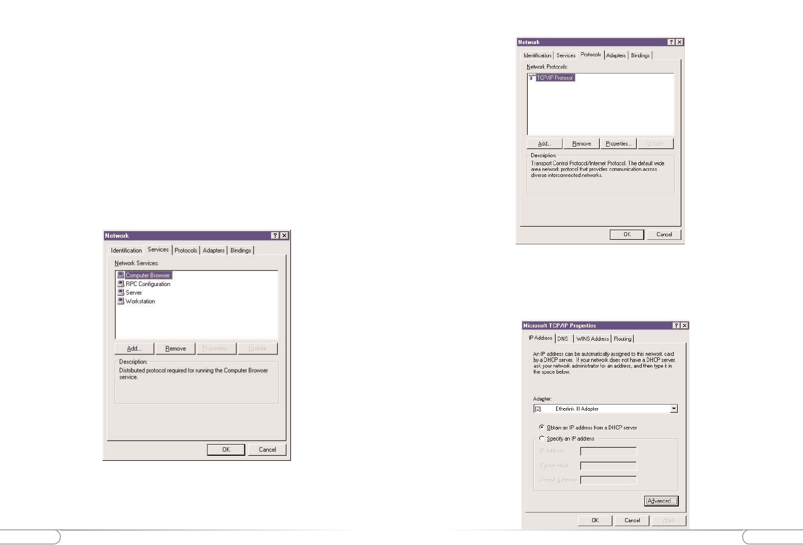
TCP/IP Properties, IP Addressing, DHCP
With the TCP/IP Protocol highlighted, click Properties, and then click the IP Address
tab and click Obtain an IP Address from a DHCP Server. Click the Advanced tab to
verify that DHCP is enabled.
Services Configuration
Click the Services tab, and make sure the following default services are listed. These are
installed by default when you initially installed TCP/IP. Note that not all of the servic-
es listed below are required for the Actiontec Wireless Cable/DSL Router. For addition-
al information, refer to your NT Workstation documentation or Microsoft support
services.
Computer Browser
RPC Configuration
Server
Workstation
If you need to add a Service, click Add and do so.
Protocol Configuration
Click the PROTOCOLS tab, and then verify that the TCP/IP Protocol is listed. If it is
not, add it.
Appendix AAppendix A 59
58
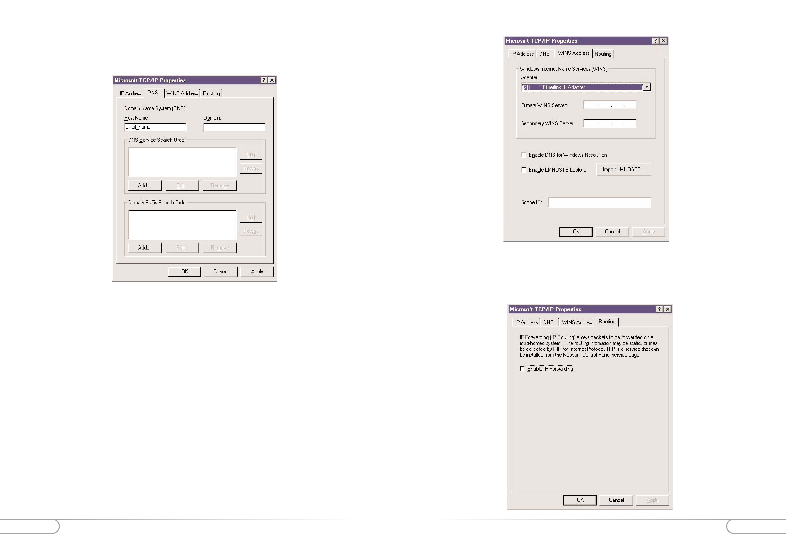
Routing Configuration
Click the Routing tab, and then verify that the Enable IP Forwarding is not checked.
Click OK to return to the Network dialog box.
DNS and Host Name Settings
Click the DNS tab to display the host name properties.
WINS Address Configuration
Click the WINS Address tab. Verify that the only entry here is your Ethernet card.
(Please see the screen image on the next page.)
Appendix AAppendix A 61
60
Click OK, then click Close and restart your computer when prompted.
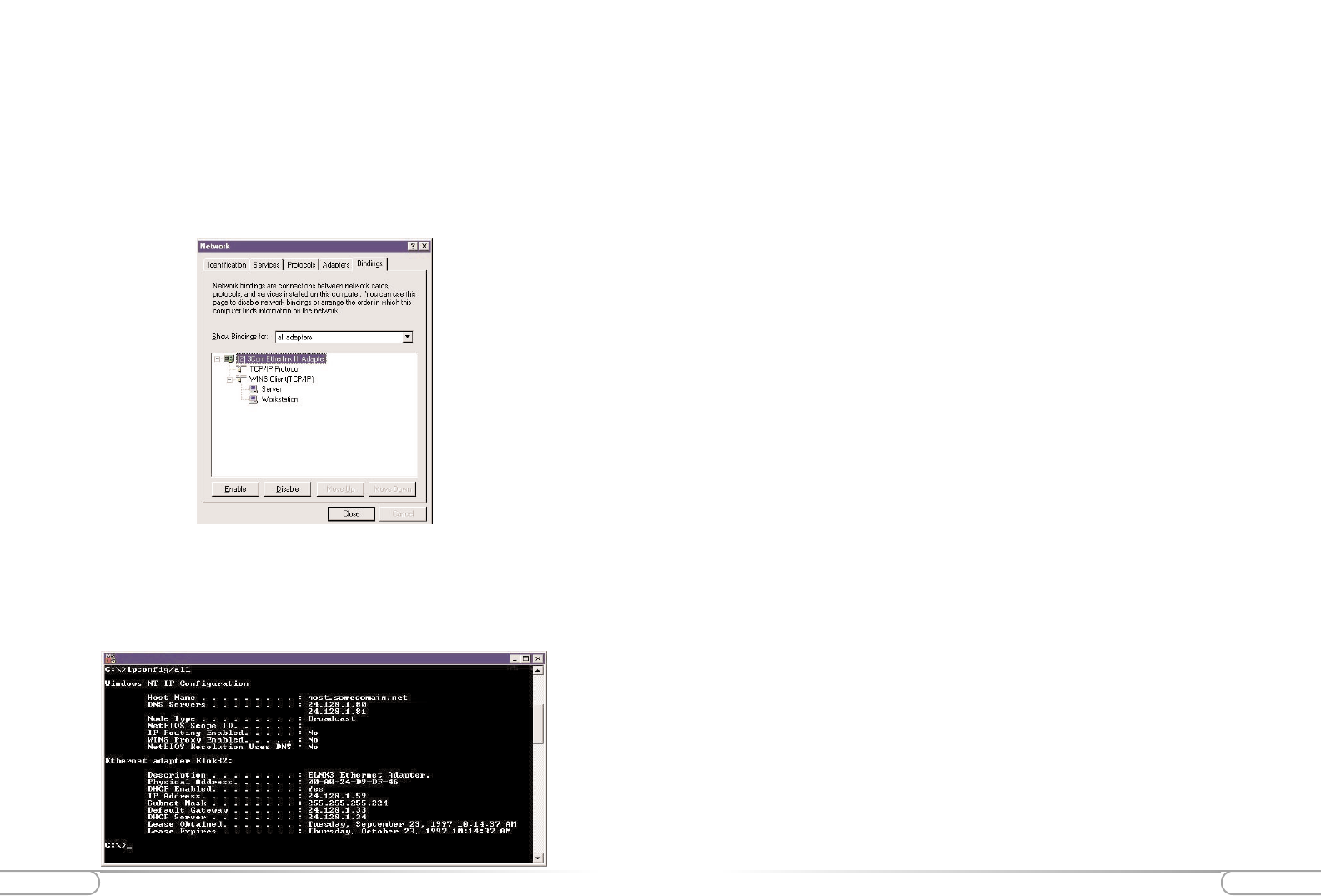
Protocols
Select All Protocols from the drop down list in the Bindings tab. (This is not the same
as the Protocols tab)
Expand all entries by clicking on plus (+) signs
TCP/IP Protocol should be bound to the adapter
WINS Client (TCP/IP) should be bound to the adapter
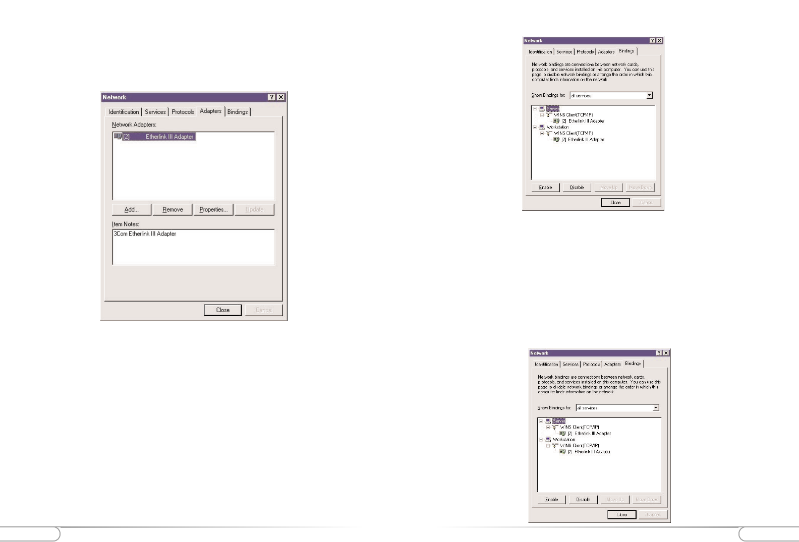
Adapter Settings
Click the Adapters tab, and then verify that your Ethernet Card is listed. If your card is
not listed, please add it.
Bindings Configuration: Protocols, Services, Adapters
The Bindings tab contains a drop down list box that allows you to display different
views of your networking configuration.
Services
Click the Bindings tab, select All Services from the drop down list, and verify that you
have at a minimum, TCP/IP bound to the Ethernet Card.
Appendix AAppendix A 63
62
Configuring TCP/IP for Windows 2000
Please make sure you have your Windows 2000 installation disks or CD-ROM handy
before beginning. Windows 2000 may need to copy some driver information during the
configuration process. If your Ethernet card was supplied with a driver diskette, be sure
to have that available as well.
Note: As with all software, you should consult your users manual or the help files
for detailed information. Actiontec provides the information that follows as a
guideline only.
Windows 2000 installs with the default TCP/IP configuration. If you have a new
machine with Windows 2000, or have just installed the Operating System, you simply
need to connect your machine to your Wireless Cable/DSL Router.
If your Windows 2000 TCP/IP settings have been changed since installation, please fol-
low the following directions. Also, make sure you have your Windows installation disks
or CD handy before beginning. If your Ethernet card was supplied with a driver
diskette, be sure to have that available as well. (Note that Windows 2000 includes built-
in drivers for some Ethernet cards)
Note: As with all software, you should consult your users manual or the help files
for detailed information. Actiontec provides the information that follows as a
guideline only.
To configure TCP/IP for Windows 2000:
1. Click on Start, and then select Settings and then Control Panel. Double click the
Network and Dial-Up Connections icon.
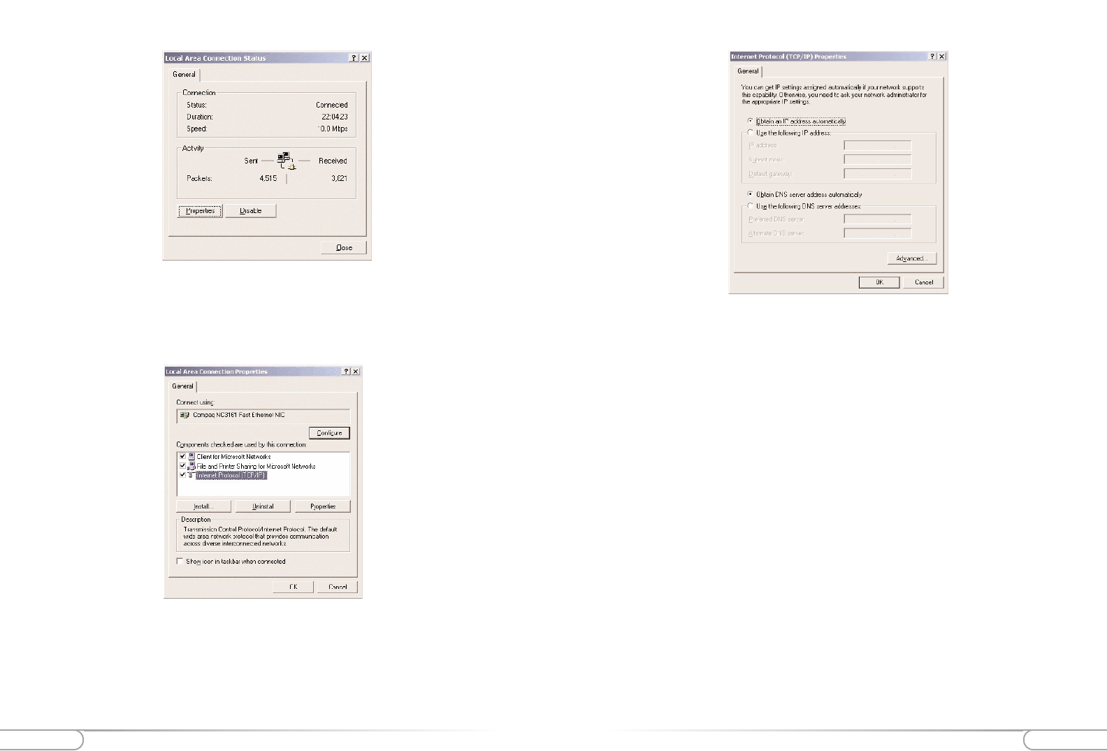
2. If the Ethernet card in your computer is installed correctly, the Local Area
Connection icon will be present. Double-click on the icon. Click Properties in the
Local Area Connection Status window.
Adapters
Select All Adapters from the drop down list in the Bindings tab.
Expand all entries by clicking on plus (+) signs
The adapter should be bound to the TCP/IP Protocol
WINS Client (TCP/IP) should be bound to Server and Workstation
Verifying Settings
After you have restarted your computer, verify your settings. Click Start, select
Programs and then select Command Prompt. At the command prompt, type "ipcon-
fig/all" to verify that you received an IP address. You may close this window once you
have verified your IP address.
Appendix AAppendix A 65
64
5. Click OK to finish
3. Under Connect Using, the Ethernet card to which the Local Area Connection in
question is pointing is displayed. Underneath, the components that are bound to
the card are shown, with a check box next to them if they are currently active. Verify
that there is a check next to TCP/IP, and place one there if it is not checked.
Highlight the Internet Protocol (TCP/IP) option, and click Properties.
4. The Internet Protocol (TCP/IP) Properties window will open. There is only one
tab. Obtain an IP address automatically should be selected in the first section, and
Obtain DNS server address automatically should be selected in the second section.
Appendix A Appendix A 67
66
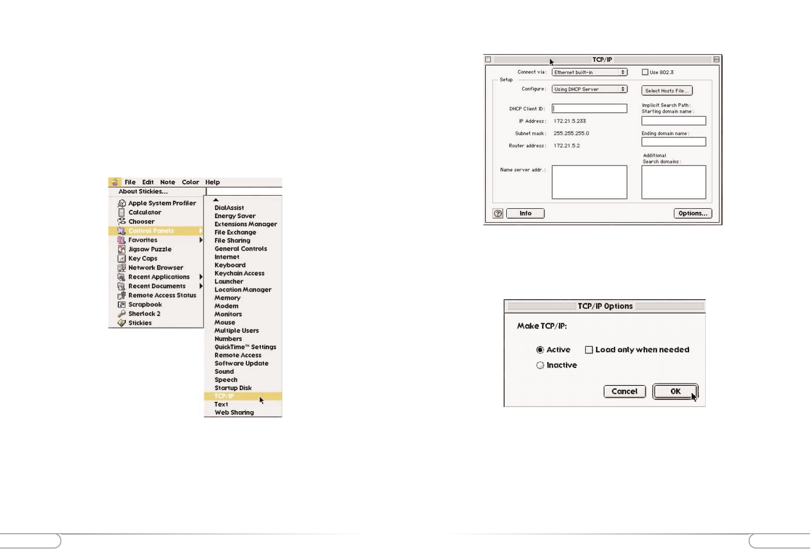
5. Make sure the Use 802.3 option is unchecked.
6. Disregard any # in the IP Address field. This will be correct after your first con-
nection.
7. Click the Options button and set TCP/IP to Active. Uncheck the option Load
only when needed, and click OK when finished.
8. No entries should be made in any of the other fields (which are shown as blank in
the sample image above).
9. Click Close Box in the upper left hand corner of the TCP/IP window, and then
select Save to save your settings.
10. Go to the toolbar and select Restart from the Special menu to restart your com-
puter.
Configuring TCP/IP For Mac OS
As with all software, you should consult your users manual or the Macintosh help files
for detailed information. Actiontec provides the information that follows as a guideline
only.
Configuring Open Transport 2.5.2
To configure Open Transport:
1. From the top toolbar, click the Apple icon. Select TCP/IP from the Control Panels
menu.
2. Once the TCP/IP control panel is open, on the top toolbar click User Mode from
the Edit menu, and set the mode to Advanced. When done, click OK.
3. In the Connect via selection, select Ethernet.
4. In the Configure selection, select Using DHCP Server.
69
Appendix A
Configuring File and Print Sharing For Windows 95, 98 and ME
With your Wireless Cable/DSL Router you can establish a network that will allow you
to share files and printers. This is an easy method to set up a network in your home or
small office. Please follow these steps to setup file and print sharing:
1. On your computer’s desktop click Start, then select Settings and then select
Control Panel. In the “Control Panel” window double click the Network icon.
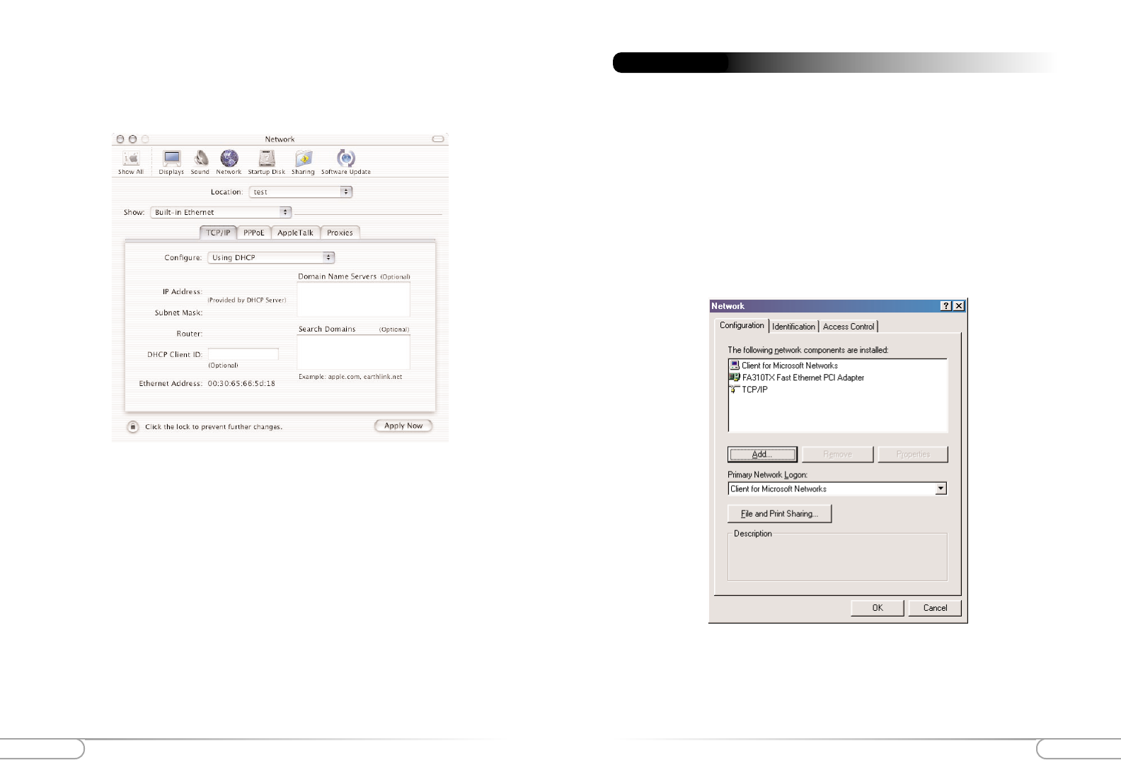
2. The following “Network” screen should appear. If File and Print Sharing is not
present, then click the Add button.
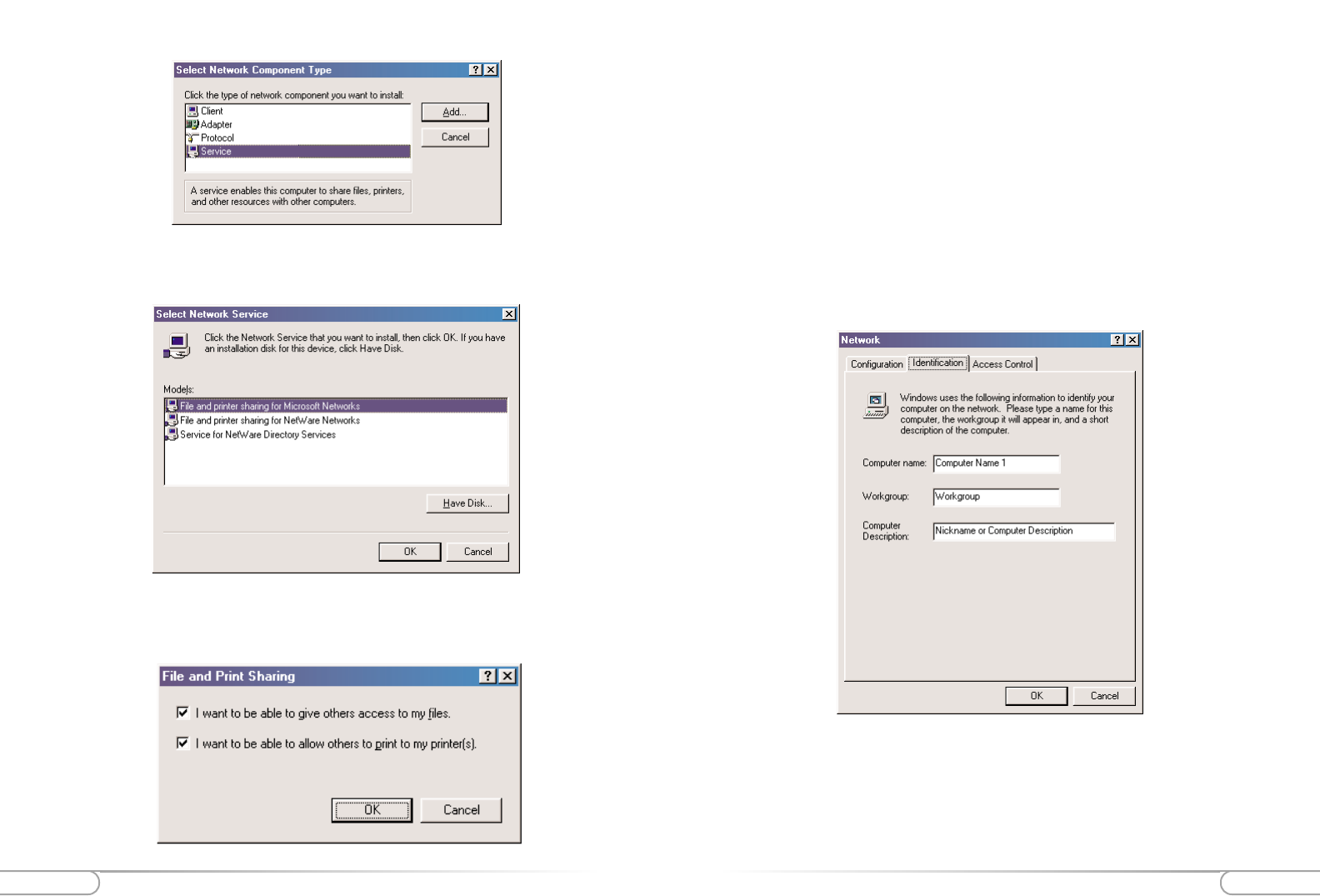
Appendix B
3. In the “Select Network Component Type” screen, click Service and then click the
Add button.
68 Appendix A
Configuring MacOS X:
To configure MacOS X for DHCP:
1. Open the System Preference application via the Dock or Apple Menu.
2. Select Built-In Ethernet from the Show menu.
3. In the TCP/IP tab, select Using DHCP from the Configure menu.
4. Click Apply Now and quit the System Preferences application.
71
Appendix B
70 Appendix A
6. After you have clicked OK you will return to the network screen from step 2. Please
click on the Identification tab (see the first image on page 26).
Computer Name: In this field you can type any name you want. (i.e. My
Computer, John, CPU654) Do not use the same name for each computer you
wish to have on your network, and we do not recommend including spaces in
the computer name.
Workgroup: This field enables you to set a unique name for your network. This
name must be set up on every other computer you wish to have on your net-
work.
Computer Description: You can enter anything you wish. Traditionally, the
location name or main user’s name is used in this field.
7. Click on the Configuration tab. This will take you back to the screen from step 2.
In the “Primary Network Logon:” box, located just above the “File and Print
Sharing” button, make sure that Client for Microsoft Networks is selected. If it is
not then click the down arrow and select it from the given list. Click OK.
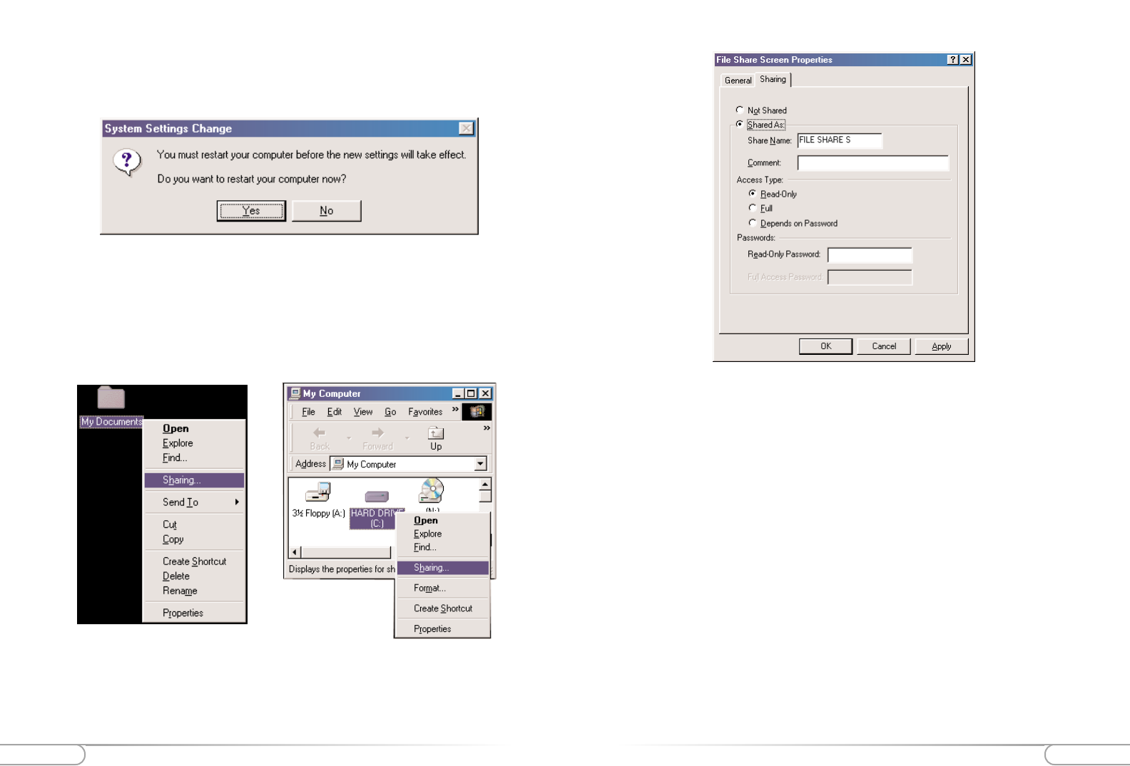
8. A screen will appear asking you to restart your computer. Click Yes to restart the
computer. If you do not see this screen please restart your computer manually. After
4. In the following screen please select File and printer sharing for Microsoft
Networks from the given list. Click OK.
5. In the “File and Print Sharing” screen make sure that both of the selections have a
check mark beside them. If they do not, please click on the box next to each state-
ment and then click OK.
73
Appendix B
72 Appendix B
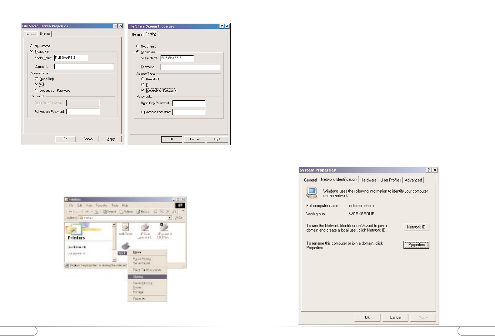
Read Only: This will allow other users on your network to view and read the file
or drive you selected. They will not be able to modify it in any way. You can fur-
ther restrict their privileges by entering a password in the appropriate field.
Full: This will allow other users on your network to read, modify, move and
delete any information in the shared drive or file. You can further restrict their
privileges by entering a user name and password.
Depends on Password: This will allow you to set both Read Only and Full access
on the shared file or drive. The level of access will depend on the passwords you
enter in the appropriate field.
When you are finished click Apply and then OK.
your computer restarts you will be asked to supply a User Name and Password.
Enter whatever you would like but be sure to write down these values, as they will
enable you to access your network.
9. After your computer has restarted and you entered a password and user name, you
must enable a file or drive for sharing. Locate the file or drive you wish to share.
(The easiest way to achieve this is through your Windows Explorer, located in the
start menu) Right click on the File or Drive you wish to share. In the given menu
select Sharing.
10. The following screen will appear. Please select Shared As. This will enable other
users on your network to see the file or drive you selected. Then you can chose the
Access Type:
75
Appendix B
74 Appendix B
13. The next step will be to enable the sharing by selecting the “Share As” button. It
will automatically insert a default name for the Share Name. You may set a pass-
word for the printer at this time if you want to restrict who on the network can use
this resource. You may also set the default printer settings by modifying informa-
tion on the other tabs of this window.
For Windows 2000
1. After you have installed and configured your PC Card, Windows 2000 will auto-
matically enable file and print sharing for your computer. The only item that needs
to be altered is your workgroup settings. All the computers on your network must
have the same workgroup name but different computer names. To check or change
this locate the “My Computer” icon on your desktop. Right click on it and select
Properties from the given list.
2. In the “System Properties” click on the Network Identification tab. If the
“Workgroup” name is already the same as all the other computers on your network,
then you do not need to change it. Click OK. If it is not the same then click
Properties.
11. Next you need to share your printer. On your desktop, click Start, click Settings,
and then select Printers.
12. Right click on the printer you want to share. Select “Sharing” from the given list.
Appendix B 77
76 Appendix B
and the buttons underneath should both say “Start”. If this is the case, file sharing
is disabled. Exit the File Sharing window.
3. If “File Sharing Off” and “Program Linking Off” is selected and the buttons
underneath indicate “Stop”, click the Stop button to disable sharing and linking.
Enter 0in the dialog box that prompts you to indicate how many minutes until file
sharing is turned off or how long before you want to disconnect other users con-
nected to your computer.
4. Click OK
5. Exit the File Sharing window.
If you need to enable file sharing on your computer, you can reduce your susceptibility
to hackers by setting a password for access to all of your shared files and directories.
To set a password:
1. Click the Apple menu in the upper left corner. Select Control Panels and then
select File Sharing.
2. Under “Network Identity”, enter an owner name and owner password. To deter
potential hackers from being able to guess your password, we recommend that your
password contain a minimum of eight characters and a mix of upper- and lower-
case letters and numbers.
3. The two sections toward the bottom should say “File Sharing Off” and “Program
Linking Off”, and the buttons underneath should both say “Start”. Click Start to
enable file sharing and/or program linking.
4. The indication above the Start button(s) will change from “Off” to “Starting Up”
to “On”.
5. Close the File Sharing window by clicking the small box in the upper left corner.
6. File sharing and/or program linking are now enabled. However, users will need to
know your Owner Name and Owner Password in order to access files or programs
on your Macintosh.
To allow others to use the printer attached to your computer:
1. Click the Apple menu in the upper left corner and scroll down to Control Panels;
then scroll right and up to Appletalk.
3. In the “Computer Name:” box type a name that is different from your other PC’s
on your network. Then, in the “Workgroup” box type the name that you are using
to identify your network. This will be the same on each computer on your network.
Click OK and you will return to the “Network Properties” screen. Click OK again
and even if you are not asked to do so, please restart your computer.
Configuring File and print sharing for MAC
There are other, much more secure ways to share your files with other Internet users. For
example, you can simply e-mail files you want to share with someone else directly to that
person or you can require a password to access your files.
Following are instructions for disabling and more securely enabling file and print shar-
ing.
To disable file sharing:
1. Click the Apple menu in the upper left corner. Select Control Panels and then
select File Sharing.
2. The default selections should be “File Sharing Off” and “Program Linking Off”,
Appendix B Appendix C 79
78
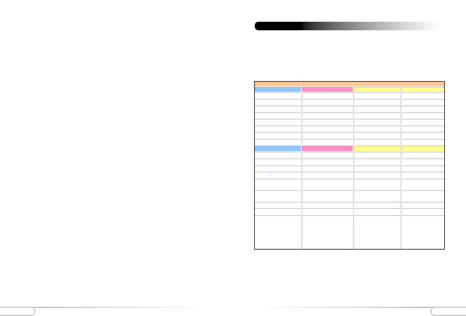
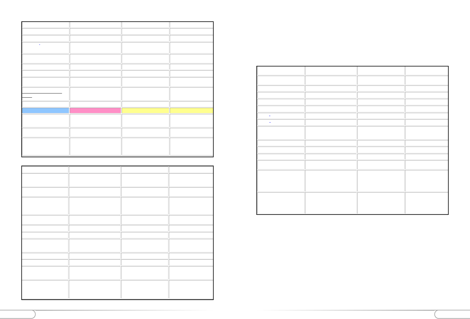
Standard Program and Port List:
Appendix C
Application Type Application Notes˚ Required Settings for Port Forwarding
SERVICES NOTES Outgoing Connection Incoming Connection
HTTP Netscape, IE None 80 /client IP
FTP Windows FTP, Cuteftp None 21 /client IP
TELNET Windows Telnet, Neterm None 23 /client IP
POP3 Eudora None 110 /client IP
SMTP Eudora None 25 /client IP
mIRC mIRC None .
Network Time Protocol (NTP) 123 123 /client IP
PPTP Windows PPTP None 1723 /client IP
APPLICATIONS NOTES Outgoing Connection Incoming Connection
BAYVPN 500 /client IP
CarbonCopy32 1023 - 1680 /client IP
CITRIX 1494 /client IP
Cu-SeeMe2Cornell 1.1 None 7648 /client IP
.White Pine 3.1.2 7648 /client IP &
24032 /client IP
Default /client IP
.White Pine 4.0
(CuSeeMe Pro )
7648 /client IP &
24032 /client IP
Default /client IP
Direct Connect 375 - 425 /client IP
FW1VPN 259 /client IP
ICQ For file transfer, we must enable:
ICQ -> preference -> connections -
> firewall and set the firewall time
out to 80 seconds in firewall
setting.
None for Chat. Default /client IP
2. In the drop-down menu after Connect via, choose Ethernet or Ethernet Built-In.
3. Close the Appletalk window by clicking the small box in the upper left corner.
4. You may be asked to save changes to your Appletalk setting. If so, click the OK but-
ton.
5. Click the Apple menu in the upper left corner and scroll down to Chooser; then,
after the word Appltalk toward the bottom right, click the radio button before the
word “Active”.
6. You'll be asked to make sure you are connected to an Appletalk network. Click the
OK button.
7. Close the Chooser window by clicking the small box in the upper left corner.
Note: When print sharing is enabled, you cannot use a password to protect your
printer. Therefore, we strongly recommend that your leave this option enabled
only during the time you wish to share your printer with other users. When the
other users have finished printing their files on your printer, we recommend you
reverse the above process. To do so, you need not change your Appletalk settings
again. All you need to do is call up Chooser and disable Appletalk by clicking
the radio button before Inactive in the lower right corner.
Appendix CAppendix C 81
80
MSN Game Zone 6667 /client IP
28800 - 29000 /client IP
MSN Game Zone (DX) 2300 - 2400 /client IP
47624 /client IP
Myth 3453 /client IP
Need for Speed 9442 /client IP
Need for Speed 3 1030 /client IP
Outlaws 5310 /client IP
Quake I4 None Default /client IP
QuakeII5 None 27910 /client IP
QuakeIII
Each computer must use a
different port number. Add 1 for
each player starting with 27660.
None 27660 (+1 for each player) /cl
i
IP
Rainbow Six 2346 /client IP 2346 /client IP
Rogue Spear 2346 /client IP 2346 /client IP
StarCraft 6112 /client IP
Tiberian Sun 1140 - 1234 /client IP
4000 /client IP
1140 - 1234 /client IP
4000 /client IP
Ultima
5001 - 5010 Game
7775 - 7777 Login
8888, 9999 Patch
8800 - 8900 Messenger
7875 Monitor
Unreal Tournament
Need to modify the
[UWeb.WebServer] section of the
server.ini file: Set ListenPort to
8080; Set ServerName to the
Public IP of your router.
7777 (game)
7778 (server)
7779 - 7783 (UdpLink)
27900 (server query)
8080 (UT Server Admin)
IP/TV Cisco IP/TV 2.0.0 None .
Laplink 1547 /client IP
Lotus Notes 1352 /client IP
NetMeeting3Microsoft NetMeeting 2.1 & 2.11 None 1720 /client IP
1503 /client IP
PC Anywhere Host must be on the LAN side and
client IP set. 22 /client IP
5631 - 5632 /client IP
RealPlayer RealPlayer G2 None .
Remote Anything 3996 - 4000 /client IP
Shiva VPN Need to set the mobile option to be
your public IP address. 2233 /client IP 2233 /client IP
Virtual Network Computing
(VNC)
5500 /client IP
5800 /client IP
5900 /client IP
VDOLive .None .
GAMES NOTES Outgoing Connection Incoming Connection
Aliens vs. Predator
80 /client IP
2300 - 2400 /client IP
8000 - 8999 /client IP
Asheron's Call May need to open MSN / DX
ports. 9000 - 9013 /client IP 9000 - 9013 /client IP
Black and White
2611 - 2612 /client IP
6500 /client IP
6667 /client IP
27900 /client IP
D
ark Reign 2 26214/client IP
D
elta Force
3100 /client IP
3568 /client IP
3999 /client IP
3100 /client IP
3568 /client IP
3999 /client IP
D
une 2000 1140 - 1234 /client IP
4000 /client IP
1140 - 1234 /client IP
4000 /client IP
E
lite Force
26000 /client IP
27500 /client IP
27910 /client IP
27960 /client IP
E
verquest
1024 - 6000 /client IP
7000 /client IP
F
-22 Lightning 3 4533 - 4660 /client IP
F
ighter Ace II 50000 - 50100 /client IP
F
ighter Ace II (DX)
2300 - 2400 /client IP
47624 /client IP
50000 - 50100 /client IP
H
alf Life 27015 /client IP
H
eretic II 28910 /client IP
H
exen II
Each computer must use a different
port number. Add 1 for each player
starting with 26900.
26900 (+1 for each player)
K
ALI
Each computer must use a different
port number. Add 1 for each player
starting with 2213.
2213 (+1 for each player) /clie
n
IP
6666 /client IP

Appendix D Appendix D 83
82
7. Make note of the Physical Address of the Ethernet Adapter (labeled 'Physical
Address') as it is the same as you MAC address
To determine the MAC address of an installed Ethernet card on Windows NT:
1. Click the Start menu
2. Select Programs
3. Select Command Prompt
4. Type: ipconfig/all
5. Press Enter
6. A window will display, with information pertaining to the Ethernet Adapter
7. Make note of the Physical Address of the Ethernet Adapter (labeled 'Physical
Address') as it is the same as you MAC address
To determine the MAC address of an installed Ethernet card on a Macintosh:
1. Select the Apple menu.
2. Select Control Panels
3. Select TCP/IP
4. Select the Info button (If the Info button does not appear, select the Edit menu,
then User Mode and then select Advanced)
5. A window will display showing the hardware address
6. Carefully make note of this Hardware address as it is the same as the MAC address
To determine the MAC address of an installed Ethernet card on Windows
95/98:
1. Click the Start menu
2. Select Run
3. In the text field type: winipcfg
4. Click OK
5. An IP Configuration window will appear
6. Carefully make note of the Adapter Address as it is the same as you MAC address
To determine the MAC address of an installed Ethernet card on Windows ME:
1. Click the Start menu
2. Select Run
3. In the text field type: winipcfg
4. Click OK
5. An IP Configuration window will appear
6. Carefully make note of the Adapter Address as it is the same as you MAC address
To determine the MAC address of an installed Ethernet card on Windows 2000:
1. Click the Start menu
2. Select Programs, and then Accessories
3. Select Command Prompt
4. Type: ipconfig/all
5. Press Enter
6. A window will display, with information pertaining to the Ethernet Adapter
Appendix D

FCC StatementFCC Statement 85
84
For questions regarding your product, or the FCC declaration, contact:
Actiontec Electronics, Inc
760 North Mary Ave,
Sunnyvale, CA 94086
United States
Tel: (408) 752-7700
Fax: (408) 541-9005
Regulatory Compliance Notices Class B Equipment
This equipment has been tested and found to comply with the limits for a Class B dig-
ital device, pursuant to Part 15 of the FCC Rules. These limits are designed to provide
reasonable protection against harmful interference in a residential installation. This
equipment generates, uses, and can radiate radio frequency energy and, if not installed
and used in accordance with the instructions, may cause harmful interference to radio
communications. However, there is no guarantee that interference will not occur in a
particular installation. If this equipment does cause harmful interference to radio or tel-
evision reception, which can be determined by turning the equipment off and on, the
user is encouraged to try to correct the interference by one or more of the following
measures:
Reorient or relocate the receiving antenna.
Increase the separation between the equipment and receiver.
Connect the equipment into an outlet on a circuit different from that to which
the receiver is connected.
Consult the dealer or an experienced radio or television technician for help.
Modifications
The FCC requires the user to be notified that any changes or modifications made to this
device that are not expressly approved by Actiontec Electronics, Inc may void the user’s
authority to operate the equipment.
Declaration of conformity for products marked with the FCC logo – United States only
This device complies with Part 15 of the FCC Rules. Operation is subject to the fol-
lowing two conditions: (1) This device may not cause harmful interference, and
(2) This device must accept any interference received, including interference that may
cause undesired operation.
"IMPORTANT NOTE: To comply with FCC RF exposure compliance requirements
the antenna used for this transmitter must be installed to provide a separation distance
of at least 20 cm from all persons and must not be co-located or operating in conjunc-
tion with any other antenna or transmitter."
FCC Statement