Actiontec Electronics SBRT8812AU ScreenBeam 802.11 a/b/g/n/ac WiFi Module User Manual Manual
Actiontec Electronics Inc ScreenBeam 802.11 a/b/g/n/ac WiFi Module Manual
Manual
PRODUCT SPECIFICATION Version 1.1
ScreenBeam 802.11 a/b/g/n/ac WiFi Module
Model Number:
SBRT8812AU
2.4G channel:1-11
5G channel:36-48 ;149-165
Custom Approval Section
Custom Name
Department
Approval Date:
DESIGN
CHECK
APPROVAL
Actiontec Electronics, Inc.
760 North Mary Ave., Sunnyvale, California 94086 United States

PRODUCTS SPECIFICATION
PAGE 2 OF 13
SBRT8812AU
Version 1.1
Document revision history
Revision Date Approved by Remarks
Version 1.0 2015-02-27 Draft
Version 1.1 2015-04-17 Adding statement

PRODUCTS SPECIFICATION
PAGE 3 OF 13
SBRT8812AU
Version 1.1
1. General Description
This document is to specify the product requirements for 802.11a/b/g/n/ac USB Module. This Card is based
on Realtek RTL8812AU chipset that complied with IEEE 802.11b/g/n/ac Draft 3.0 compatible WLAN ,and it
is also backward complied with IEEE 802.11a standard from 5.15~5.825GHz wideband and IEEE
802.11b/g standard from 2.4~2.5GHz. It can be used to provide up to 54Mbps for IEEE 802.11a and IEEE
802.11g,11Mbps for IEEE 802.11b and 150Mbps for IEEE 802.11n and 433.3Mbps for IEEE 802.11ac to
connect your wireless LAN.
With seamless roaming, fully interoperability and advanced security with WEP standard, 802.11
a/b/g/n/ac USB Module offers absolute interoperability with different vendors 802.11a/b/g/n/ac.Access
Points through the wireless LAN.
2. Features
z
Compatible with IEEE 802.11b standard to provide wireless 11Mbps date rate.
z
Compatible with IEEE 802.11g standard to provide wireless 54Mbps date rate.
z
Compatible with IEEE 802.11n standard to provide wireless 150Mbps date rate.
z
Compatible with IEEE 802.11ac standard to provide wireless 433.3Mbps date rate.
z
Operation at 2.4~2.5GHz and 5.15~5.825GHz frequency band to meet worldwide regulations
z
Provides simple legacy and 20MHz/40MHz/80MHz co-existence mechanisms to ensure backward and
network compatibility.
z
Supports infrastructure networks via Access Point and ad-hoc network via peer-to-peer communication
z
Supports IEEE 802.11i(WPA and WPA2),WAPI,. enhanced security
z
Friendly user configuration and diagnostic utilities
z
Drivers support Windows XP,Vista.Win7
z
High speed USB 2.0 interface
z
ROHS compliant
PRODUCTS SPECIFICATION
PAGE 4 OF 13
SBRT8812AU
Version 1.1
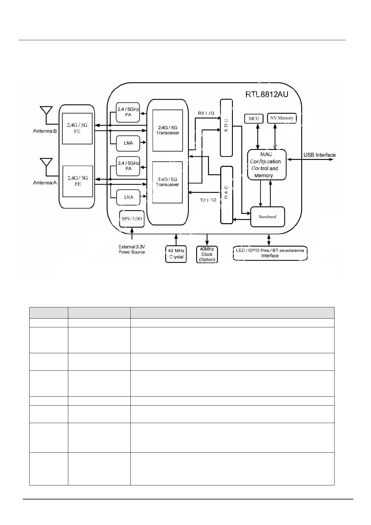
3. Application Diagrams
3.1
Functional Block Diagram
3.2 General Requirements
3.2.1 IEEE 802.11b Section
Feature
Detailed Description
3.2.1.1 Standard ● IEEE 802.11b
3.2.1.2
Radio and
Modulation
Schemes
● DQPSK , DBPSK , DSSS , and CCK
3.2.1.3 Operating
Frequency ● 2412 ~ 2472MHz ISM band
3.2.1.4 Channel Numbers
● 11 channels for United States
● 13 channels for Europe Countries
● 14 channels for Japan
3.2.1.5 Data Rate ● 11,5.5,2,and 1Mbps
3.2.1.6 Media Access
Protocol ● CSMA/CA with ACK
3.2.1.7
Transmitter Output
Power at Antenna
Connector
● Typical RF Output Power at each RF chain,Data Rate and
at room Temp. 25℃
● 17dBm(±2dB) at 1,2,5.5,11Mbps
3.2.1.8
Receiver
Sensitivity
at Antenna
Connector
● Typical Sensitivity at Which Frame(1000-byte PDUs)Error
Rate=8%
● -76 dBm at 2Mbps
● -76 dBm for 11Mbps

PRODUCTS SPECIFICATION
PAGE 5 OF 13
SBRT8812AU
Version 1.1
3.2.2 IEEE 802.11g Section
Feature
Detailed Description
3.2.2.1 Standard ● IEEE 802.11
g
3.2.2.2 Radio and
Modulation T
y
pe ● QPSK , BPSK , 16QAM ,64QAM with OFDM
3.2.2.3 Operating
Frequenc
y
● 2412 ~ 2472MHz ISM band
3.2.2.4 Channel Numbers
● 11 channels for United States
● 13 channels for Europe Countries
● 13 channels for Japan
3.2.2.5 Data Rate ● 6,9,12,18,24,36,48,54Mbps
3.2.2.6 Media Access
Protocol ● CSMA/CA with ACK
3.2.2.7
Transmitter Output
Power at Antenna
Connector
● Typical RF Output Power(tolerance±2dB) at each RF chain,
Data Rate and at roomTemp. 25℃
● +17 dBm at 6,9Mbps
● +16 dBm at 12,18Mbps
● +15 dBm at 24,36Mbps
● +14 dBm at 48,54Mbps
3.2.2.8
Receiver
Sensitivity
at Antenna
Connector
● Typical Sensitivity at each RF chain. Frame(1000-byte
PDUs)Error Rate<10% at room Temp 25℃
● -82 dBm at 6Mbps
● -81 dBm at 9Mbps
● -79 dBm at 12Mbps
● -77 dBm at 18Mbps
● -74 dBm at 24Mbps
● -70 dBm at 36Mbps
● -66 dBm at 48Mbps
● -65 dBm at 54Mbps

PRODUCTS SPECIFICATION
PAGE 6 OF 13
SBRT8812AU
Version 1.1
3.2.3 IEEE 802.11a Section
Feature
Detailed Description
3.2.3.1 Standard ● IEEE 802.11a
3.2.3.2 Radio and
Modulation T
yp
e ● QPSK , BPSK , 16QAM ,64QAM with OFDM
3.2.3.3 Operating
Frequency
● 5.18 ~ 5.24GHZ, 5.745~5.825GHz for US and Canada
● 5.18 ~ 5.24GHZ, 5.745~5.825GHz for Japan
● 5.18 ~ 5.24GHZ, 5.745~5.825GHz Hz for Europe
● 5.18 ~ 5.24GHZ, 5.745~5.825GHz for China
3.2.3.4 Channel Numbers
● 12 non-overlapping channels for US and Canada
● 8 non-overlapping channels for Japan
● 19 non-overlapping channels for Europe
● 4 non-overlapping channels for China
3.2.3.5 Data Rate ● 6,9,12,18,24,36,48,54Mbps
3.2.3.6 Media Access
Protocol ● CSMA/CA with ACK
3.2.3.7
Transmitter
Output
Power at Antenna
Connector
● Typical RF Output Power(tolerance±2dB) at each RF chain,
Data Rate and at roomTemp. 25℃
● +14 dBm at 6,9Mbps
● +13 dBm at 12,18Mbps
● +12 dBm at 24,36Mbps
● +11 dBm at 48,54Mbps
3.2.3.8
Receiver
Sensitivity
at Antenna
Connector
● Typical Sensitivity at each RF chain. Frame(1000-byte
PDUs)Error Rate<10% at room Temp 25℃
● -82 dBm at 6Mbps
● -81 dBm at 9Mbps
● -79 dBm at 12Mbps
● -77 dBm at 18Mbps
● -74 dBm at 24Mbps
● -70 dBm at 36Mbps
● -66 dBm at 48Mbps
● -65 dBm at 54Mbps
PRODUCTS SPECIFICATION
PAGE 7 OF 13
SBRT8812AU
Version 1.1
3.2.4 IEEE 802.11n Section
Feature
Detailed Description
3.2.4.1 Standard ● IEEE 802.11n
3.2.4.2 Radio and
Modulation Type
● BPSK , QPSK , 16QAM ,64QAM with OFDM
3.2.4.3 Operating
Frequency
● 2.4GHz band:2412 ~ 2472MHz 2412 ~ 2462MHz (for FCC)
● 5GHz and:5.18 ~ 5.24GHZ, 5.745~5.825GHz
3.2.4.4 Data Rate
MCS GI=800ns GI=400ns
20MHz 40MH
20MHz
40MHz
0 6.5 13.5 7.2 15
1 13 27 14.4 30
2 19.5 40.5 21.7 45
3 26 54 28.9 60
4 39 81 43.3 90
5 52 108 57.8 120
6 58.5 121.5 65.0 135
7 65 135 72.2 150
3.2.4.5 Media Access
Protocol
● CSMA/CA with ACK
3.2.4.6
Transmitter Output
Power at Antenna
Connector
● Typical RF Output Power(tolerance±2dB) at each RF chain,Data Rate and
at roomTemp. 25℃
● 2.4GHz Band/HT20
+14dBm at MCS0~7
● 2.4GHz Band/HT40
+14dBm at MCS0~7
● 5GHz Band/HT20
+11dBm at MCS0~7
● 5GHz Band/HT40
+11dBm at MCS0~7
3.2.4.7
Receiver Sensitivity
at Antenna
Connector
Typical Sensitivity at each RF chain at Which Frame(1000-byte PDUs)Error
Rate=10% and at room Temp. 25℃
2.4GHz Band/HT20
● -82dBm at MCS0
● -79dBm at MCS1
● -77dBm at MCS2
● -74dBm at MCS3
● -70dBm at MCS4
● -66dBm at MCS5
● -65dBm at MCS6
● -64dBm at MCS7
2.4GHz Band/HT40
● -79dBm at MCS0
● -76dBm at MCS1
● -74dBm at MCS2
● -71dBm at MCS3
● -67dBm at MCS4
● -63dBm at MCS5
● -62dBm at MCS6
● -61dBm at MCS7
5GHz Band/HT20
● -82dBm at MCS0
● -79dBm at MCS1
● -77dBm at MCS2
● -74dBm at MCS3
● -70dBm at MCS4
● -66dBm at MCS5
● -65dBm at MCS6
● -64dBm at MCS7
5GHz Band/HT40
● -79dBm at MCS0
● -76dBm at MCS1
● -74dBm at MCS2
● -71dBm at MCS3
● -67dBm at MCS4
● -63dBm at MCS5
● -62dBm at MCS6
● -61dBm at MCS7
PRODUCTS SPECIFICATION
PAGE 8 OF 13
SBRT8812AU
Version 1.1
3.2.5 IEEE 802.11ac Section
Feature
Detailed Description
3.2.5.1 Standard ● IEEE 802.11ac
3.2.5.2 Radio and
Modulation T
yp
e ● QPSK , BPSK , 16QAM ,64QAM,256QAM with OFDM
3.2.5.3 Operating
Frequency
● 5.18 ~ 5.24GHZ, 5.745~5.825GHz for US and Canada
● 5.15~5.35GHz and 5.47~5.725GHz for Japan
● 5.15~5.35GHz and 5.47~5.725GHz for Europe
● 5.725~5.825GHz
f
or China
3.2.5.4 Channel Numbers
● 12 non-overlapping channels for US and Canada
● 8 non-overlapping channels for Japan
● 19 non-overlapping channels for Europe
● 4 non-overlapping channels for China
3.2.5.5 Data Rate ● at most 433.3 Mbps
3.2.5.6 Media Access
Protocol ● CSMA/CA with ACK
3.2.5.7
Transmitter
Output
Power at Antenna
Connecto
r
● Typical RF Output Power(tolerance±2dB) at each RF chain,
Data Rate and at roomTemp. 25℃
● +11 dBm at HT20 / HT40
3.2.5.8
Receiver
Sensitivity
at Antenna
Connector
● Typical Sensitivity at each RF chain. Frame(1000-byte
PDUs)Error Rate<10% at room Temp 25℃
5GHz Band / HT20
● -82dBm at MCS0
● -79dBm at MCS1
● -77dBm at MCS2
● -74dBm at MCS3
● -70dBm at MCS4
● -66dBm at MCS5
● -65dBm at MCS6
● -64dBm at MCS7
● -59dBm at MCS8
● -57dBm at MCS9
5GHz Band / HT40
● -79dBm at MCS0
● -76dBm at MCS1
● -74dBm at MCS2
● -71dBm at MCS3
● -67dBm at MCS4
● -63dBm at MCS5
● -62dBm at MCS6
● -61dBm at MCS7
● -56dBm at MCS8
● -54dBm at MCS9
5GHz Band / HT80
● -76dBm at MCS0
● -73dBm at MCS1
● -71dBm at MCS2
● -68dBm at MCS3
● -64dBm at MCS4
● -60dBm at MCS5
● -59dBm at MCS6
● -58dBm at MCS7
● -55dBm at MCS8
● -51dBm at MCS9
PRODUCTS SPECIFICATION
PAGE 9 OF 13
SBRT8812AU
Version 1.1
4. Electrical and Thermal Characteristics
4.1
Temperature
Limit
Ratings
Parameter
Minimum
Maximum
Units
Storage
Temperature
-40
+80
℃
Ambient
Operating
Temperature
0
60
℃
Junction
Temperature
0
125
℃
4.2
General Section
Feature Detailed Description
5.2.1 Antenna Type ● Integrated antenna
5.2.2 Operating Voltage ● 5V±10%
5.2.3 Current Consumption ● <900mA
5.2.4 Form Factor and Interface ● High Speed USB2.0 Interface
4.3 Software
Driver Windows XP/ WinCE/ Vista,/ Win7, Linux, MAC
Security 64/128-bits WEP, WPA, WPA2
PRODUCTS SPECIFICATION
PAGE 10 OF 13
SBRT8812AU
Version 1.1
5 Connector Definition
5-Pin 1.25 mm PAD
Pin 1 2 3 4 5
Definition Power_EN GND D+ D- VDD(+5V)
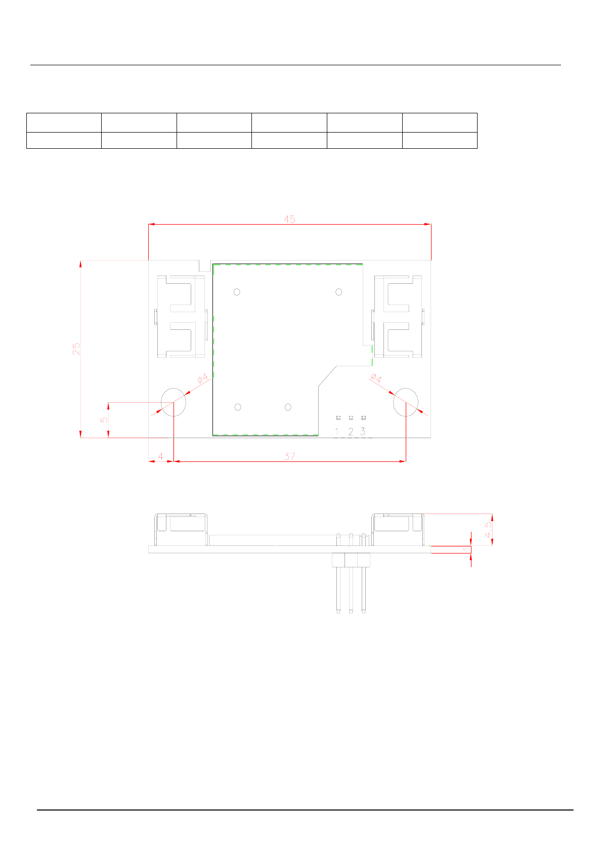
6 Mechanical Dimensions
*TLERANCES ARE +/-0.5mm UNLESS OTHERWISE SPECIFIED
*UNIT:mm
PRODUCTS SPECIFICATION
PAGE 11 OF 13
SBRT8812AU
Version 1.1
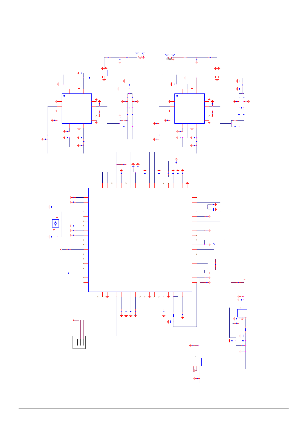
Appendix 1 : Schematic
5GFE M0_P5
5GFEM1_P5
5G_0
D+HSDP
D-HSDM
5G_1 2G_1
EN_P1
LX
L11
10nH
NetDX1_5
NetC69_1
NetCON0_1NetCON0_2
NetC51_1
NetC11_2
NetC51_2
L7
10nH
C67
4p7F
PAPE_5G_1
PAPE_5G_0
PDn
RF2ON_1
RREF
SPS_P3
RF5IP_0
RF5OP_0
TRSW_ 0
RF5OP_1
RF5IP_1
RF2OP_1
V12RF
V12RF
V12
V12
TRSWB_ 0
TRSW_1
TRSWB_1
V12
V33
V12
V33
V33
C25
15pF
C27
0u1F C37
0u1F
C51
0u1F
C78
4p7F
XTALP3
0R
R9
C26
15pF
V33
C61
0u1F
C28
0u1F
C72
10uF
C70
0u1F
NetC51_2
XO
C46
0u1F
C15
0u1F
C38
0u1F
C43
0u1F
C54
0u1F
C55
0u1F
RF2OP_0
RF2ON_0
R16
22K
R15
100K
100K
R7
R1
150K
L1
4u7H
Q1
G5728
SW 3
EN 1
GND 2
FB
5VIN
4
C88
100pF
V33
C85
0u1F
C1
10uF
C42
1uF
C10
10pF
C84
10pF
RF2ON_1
RF2OP_1
V33
C71
10uF
C16
0u1F
C24
1uF
V33
C50
0p3F
C60
1uF
C59
1uF
C52
1uF
C18
0p3F
C6
4p7F
C3
10pF
C
NP
C35
1p2F
C64
1p2F
10K
R6
C
NP
TRN_0
TR P _0
V33
V12
V33
V33
ANT1
1
2
3
4
L12
1nH
C9
NP C17
10uF
C63
1uF
V33
V33
C57
4p7F
5G FEM
IC3
GND
3
GND 7
GND
14
PA_EN 6
GND
1
VCC1 10
VDD 11
GND 17
VCC2
4
RX
2
CRX
15
TX 8
ANT
13
GND 12
NC 9
VDET 5
LNA_EN
16
C93
1uF L8
1n2H
C90
NP
100K
R42
C
NP
C
NP
V33
RF2OP_0
RF2ON_0
5G FEM
IC2
GND
3
GND 7
GND
14
PA_EN 6
GND
1
VCC1 10
VDD 11
GND 17
VCC2
4
RX
2
CRX
15
TX 8
ANT
13
GND 12
NC 9
VDET 5
LNA_EN
16
L2
1n2H
C69
0u1F
C68
0u1F
V33
C13
1uF C12
1uF
C
NP C
NP
C34
4.7pF
C8
10pF
100K
R1
C98
1uF
C
NP
C23
NP
V33
2G_0
TX5G_1
XIXIXIXIXIXIXIXIXIXIXIXIXIXIXIXI
5V
FB_P5
NetDX0_5
5V
V12
V33V33 V33
GND
RF5IP_1
V33
RF5IP_0
5GFEM0_P13
V12
VD12
V12RF
VD12RF_0
V12
RF5OP_1
V33
PAPE_5G_1
V33
V33
5GFEM1_P16
TR SW B_ 1
TR SW B_ 0
TR SW B_ 1
RX5G_0
TR SW B_ 0
5GFEM0_P16
PAPE_5G_0
V33
RF5OP_0
V12
V33
C62
1uF
V12
V12L
RTL8812AU
IC1
RF2IN_S1 67
RF2IP_S0
5
RF2IN_S0
4
V12_BB_S0
14
RF5IP_S0
12
VD33PA5G_S0
11
V12_AFE_S0
15
V12_S0
3
RF5IN_S0
13
V33_SYS
1
RF2ON_S0
7
PAPE_2G_S0
16
GND
77
RF2OP_S0
8
V33_PAD2G_S0
6
RF5OP_S0
10
V33_PAD5G_S0
9
TRSWB_S0
19
GPIO[1]
38
TRSW_S0
18
VD12A
20
LED2 / GP IO[8]
33
XI
22
XO
23
CK_BT
24
ANTSW
25
VD33A
21
GPIO[7] / BT_P RI
32
ANTSWB
26
VD12D
27
VD33D
28
GPIO[4] / WL_ACT
29
GPIO[5] / BT_RFQ / BT_EN
30
GPIO[6] / BT_S TATE
31
PAPE_5G_S0
17
LED1 / GP IO[9]
34
LED0 / GP IO[10]
35
GPIO[11] / PDn
36
GPIO[0] / BT_Suspend
37
GPIO[2] 39
GPIO[3] 40
VDSPS33 57
FB_SPS 58
GND 54
LX_SPS0 56
LX_SPS0 55
VD33D 59
VD12D 60
TRSW_S1 62
TRSWB_S1 61
PAPE_5G_S1 63
PAPE_2G_S1 64
V12_AFE_S1 65
V12_BB_S1 66
RF5IN_S1 76
RF5IP_S1 75
VD33PA5G_S1 74
RF5OP_S1 73
V12_SYS
2
V33_PAD5G_S1 72
RF2ON_S1 70
RF2OP_S1 71
V33_PAD2G_S1 69
RF2IP_S1 68
GND 41
HSDP 42
HSDM 43
VD12S 44
VD33S 45
RREF 46
VDDTX 47
GND 50
HSIN 51
HSON 48
HSOP 49
VDDRX 53
HSIP 52
C48
10uF
C13
10uF
L10
4u7H
24K
R11
L9
10nH
C66
4p7F
L5
2n7H
C33
5p6F
C39
5p6F
C21
1p2F
L6
10nH
L3
2n7H
X1
40MHz
XTALP
122
XTALP 3
4
4
U2
8025-A1
P1
5
P3 1
P2 3
G2
G
4
G
6
U1
8025-A1
P1
5
P3 1
P2 3
G2
G
4
G
6
C44
1nF
C29
0u1F
C45
0u1F
C48
0.1uF
C23
0p75F
L4
2n7H
C14
1p0F
C40
0u1F
C82
0p75F C80
0p75F
C4
10pF
L14
2n7H
5V
D-
5V
GND
D+
Po w e r EN
NC
PowerEN
PowerEN
D+
D_
5V
V12
V12
LX5586
LX5586
0R
R12
VD12
5GFEM1_P13
RX5G_1
TX5G_0
TR P _1
L16
1nH
0R
R14
V12
C74
1p2F L2
2n7H
C75
1p2F
L13
2n7H
NetC11_2
V12 V12RF
Q2
G9091
SW 3
EN 1
GND 2
FB
5VIN
4
0R
R4
C1
10uF
VD12
V33
C86
10uF
V12L
C
NP
C81
NP
NetCON1_1
C22
1p2F
ANT2
1
2
3
4
100K
R10

PRODUCTS SPECIFICATION
PAGE 12 OF 13
SBRT8812AU
Version 1.1
Appendix 2 : Statement
FCC Important Notes:
(1)
FCC Statement
This equipment complies with FCC RF radiation exposure limits set forth for an uncontrolled environment. This
transmitter must not be co-located or operating in conjunction with any other antenna or transmitter.
This equipment complies with Part 15 of the FCC Rules. Operation is subject to the following two conditions:
(1) This device may not cause harmful interference, and
(2) This device must accept any interference received, including interference that may cause undesired
operation.
The devices must be installed and used in strict accordance with the manufacturer’s instructions as described in
the user documentation that comes with the product. Modular could be only used in mobile or fix device, and
could not be used in any portable device.
Caution!
The manufacturer is not responsible for any radio or TV interference caused by unauthorized modifications to this
equipment. Such modifications could void the user authority to operate the equipment.
FCC Radiation Exposure Statement
This equipment complies with FCC radiation exposure limits set forth for an uncontrolled environment. This
equipment should be installed and operated with minimum distance 20cm between the radiator and your body.
This device and it’s antennas(s) must not be co-located or operating in conjunction with any other antenna or
transmitter except in accordance with FCC multi-transmitter product procedures.
(2)
Co-location Warning:
This device and its antenna(s) must not be co-located or operating in conjunction with any other antenna or
transmitter.
(3)
OEM integration instructions:
This device is intended only for OEM integrators under the following conditions:
The transmitter module may not be co-located with any other transmitter or antenna. The module shall be only
used with the integral antenna(s) that has been originally tested and certified with this module.
As long as 3 conditions above are met, further transmitter test will not be required. However, the OEM integrator
is still responsible for testing their end-product for any additional compliance requirements required with this
module installed (for example, digital device emissions, PC peripheral requirements, etc.).
(4)
Validity of using the module certification:
In the event that these conditions cannot be met (for example certain laptop configurations or co-location with
another transmitter), then the FCC authorization for this module in combination with the host equipment is no
longer considered valid and the FCC ID of the module cannot be used on the final product. In these
circumstances, the OEM integrator will be responsible for re-evaluating the end product (including the transmitter)
and obtaining a separate FCC authorization.
(5)
End product labeling:
The final end product must be labeled in a visible area with the following:
“Contains Transmitter Module FCC ID: LNQSBRT8812AU”.
(6)
Information that must be placed in the end user manual:
The OEM integrator has to be aware not to provide information to the end user regarding how to install or remove
this RF module in the user's manual of the end product which integrates this module. The end user manual shall
include all required regulatory information/warning as show in this manual.

PRODUCTS SPECIFICATION
PAGE 13 OF 13
SBRT8812AU
Version 1.1
FCC Caution: Any changes or modifications not expressly approved by the party responsible for compliance
could void the user’s authority to operate this equipment.
IEEE 802.11b or 802.11g operation of this product in the USA is firmware-limited to channels 1 through 11.
The device for the band 5150-5250 MHz is only for indoor usage to reduce the potential for harmful interference
to co-channel mobile satellite systems.