Actiontec Electronics SBWD950A ScreenBeam Pro Enterprise Edition User Manual
Actiontec Electronics Inc ScreenBeam Pro Enterprise Edition
UserManual.wiki
>
Actiontec Electronics
>
SBWD950A User Manual
User Manual
Navigation menu
Upload a User Manual
Namespaces
Wiki Guide
HTML
PDF
Info
Views
User Manual
Discussion / Help
Navigation

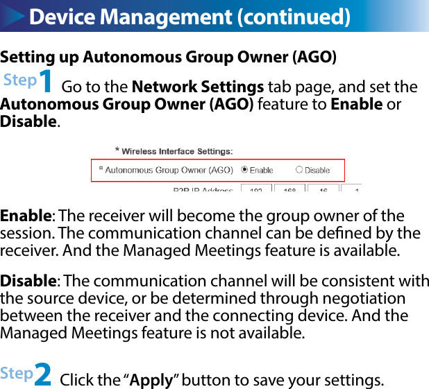
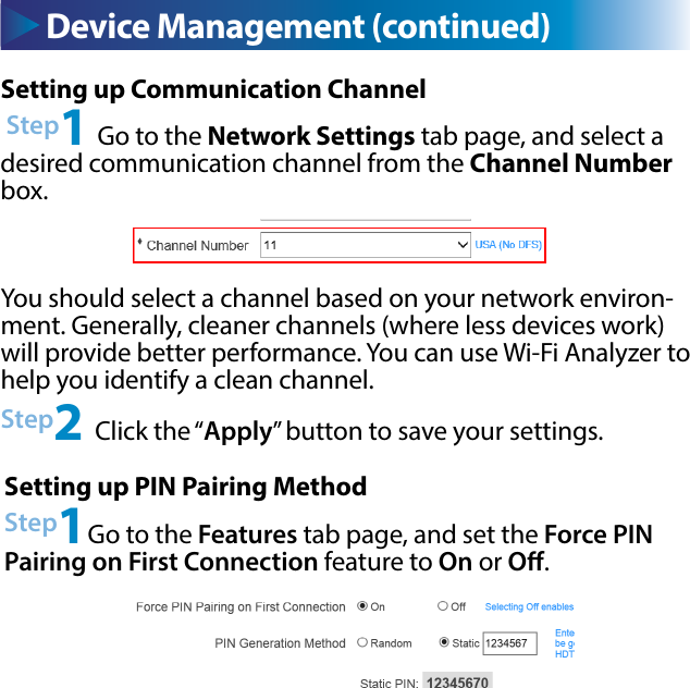
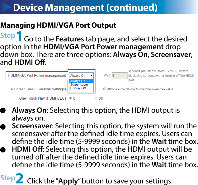
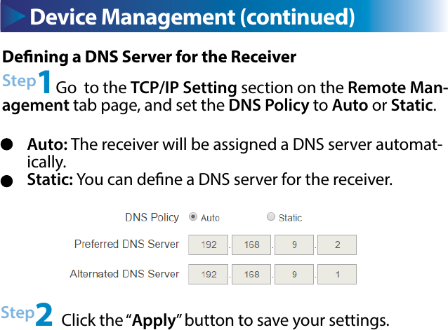
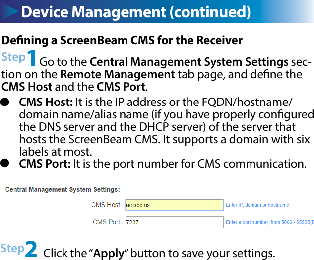
![Device Management (continued) Device Management (continued)Setting up Wireless Connection PropertiesStep1Go to the Wireless Connection Property Settings section in the Remote Management tab page, and select a desired Security Type and provide correct information for relevant items.Step2 Click the Connect button, and then the adapter will connect to the wireless router (AP).Note: Available security types are Open, Shared, WPA-PSK[T-KIP], WPA2-PSK[AES], WPA-PSK[TKIP]+WPA2-PSK[AES], PEAP/MSCHAPV2, and EAP-TLS.](https://usermanual.wiki/Actiontec-Electronics/SBWD950A/User-Guide-2758084-Page-19.png)