Actiontec Electronics SBWD950A ScreenBeam Pro Enterprise Edition User Manual
Actiontec Electronics Inc ScreenBeam Pro Enterprise Edition
User Manual
Wireless Display Receiver
Installation Guide
This Installation Guide will walk you through the easy steps
to set up your ScreenBeam Pro Wireless Display Receiver -
Enterprise Edition. During this process, we’ll show you how to
A Install the Receiver
B1 Connect Using Windows 8.1 or Higher
B2 Connect Using Intel WiDi App (Gen 5)
B3 Connect Using WiFi Miracast-enabled Device
C Switch Display Modes
D Device Management
Model# SBWD950A
Part No:
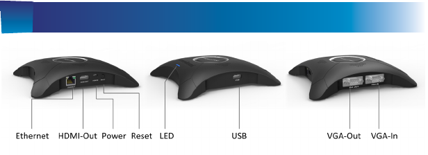
Meeting ScreenBeam Pro
Ethernet: connects to ScreenBeam Central Management
System via Ethernet for receiver management
HDMI Out: connects to HDTV/projector with an HDMI port
for video and audio output
Power: for power supply
Reset: resets system to defaults
LED Indicator: indicates power supply status
USB: for conguring CMS connection data, rmware update,
and USB control
VGA Out: connects to HDTV/projector with a VGA port for
video output
VGA In: VGA input for VGA bypass

Welcome!
Step2 Plug one end of the HDMI/VGA cable into the HDMI/
VGA Out port on the Receiver, and the other end into an
available HDMI/VGA port on the HDTV/Projector.
Step3 Plug the connector of the power cord into the Power
port of the Receiver, and the AC adapter into a power outlet.
A Install the Receiver
Thank you for your purchase of a ScreenBeam Pro Wireless
Display Receiver - Enterprise Edition (hereinafter referred to
as the Receiver). The Receiver connects to your Intel WiDi or
Miracast-capable device wirelessly, and displays the device’s
screen on your HDTV.
Step1 Get the Receiver, power adapter, and HDMI cable or
VGA cable from the Receiver’s box.
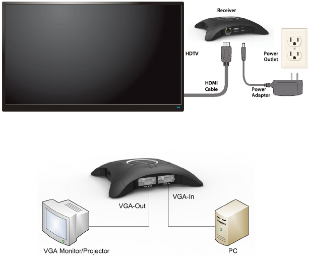
Step4 Turn on your TV and switch the input source until
you see the Ready To Connect screen.
Step5 (Optional) VGA bypass connection is shown below:
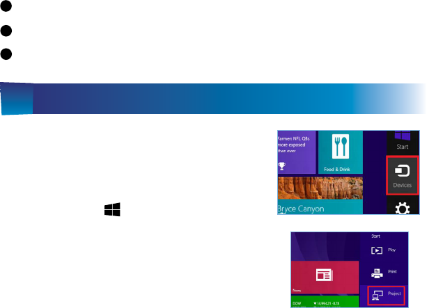
B1 Connect Using Windows 8.1 or Higher
Step1 From the Windows desktop,
navigate to the Charms menu and
select Devices. You can also use the
shortcut keys, + K.
Step2 From the Charms menu,
click the Project icon.
The Receiver is now connected to your HDTV. Proceed to one
of the next three sections of this Guide (depending on the
device you are using to connect to the Receiver) to nish the
connection procedure.
For Windows 8.1 devices, please proceed to section B1;
For Windows 7/8 devices, please proceed to section B2;
For Android devices, please proceed to section B3.
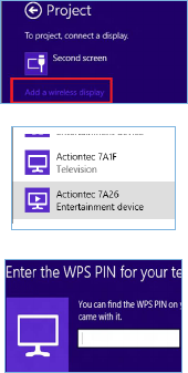
Step4 Select the ScreenBeam
Receiver from the list.
Step5 Enter the PIN displayed on
the television screen, then connect
and display.
Note: If you are running Windows 8.1 and the screens above
do not appear, go to http://www.actiontec.com/widi81 for
the latest software updates.
Step3 From the Project screen,
select Add a wireless display.
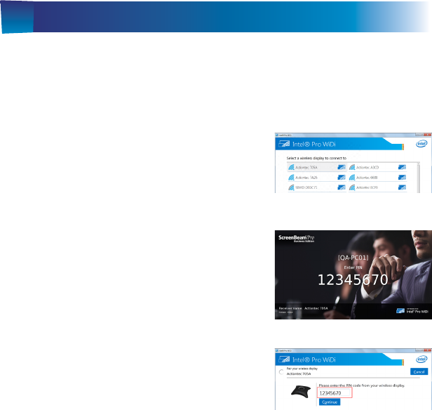
Step2 The device scans for
available receivers. Select your
receiver on the list to connect to the
receiver.
Step3 A PIN and the host name
of the connecting device are dis-
played. Enter the PIN in the PIN
entry box on the WiDi device, and
click Continue.
Step1Find the Intel Wireless Display application on the
device and launch it. To nd the application, go to Windows
Search on your device and search for “Intel WiDi” in your apps.
B2 Connect Using Intel WiDi App (Gen 5)
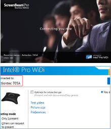
Step4 The HDTV displays
messages to show the status of the
connection process.
Step5 Your device will connect to
the receiver, and the device’s screen
will be displayed on the HDTV.
Note: Connection using Intel WiDi (4.x.x.x) is available when
the receiver’s AGO feature is disabled. Connection procedure
is similar.

Step2 The Wireless Display Application scans for available
receivers. Select your receiver from the list.
Step3 Enter the PIN displayed on the TV screen if required,
and then connect.
Step1 On a Miracast-enabled Android device, locate and
open the Wireless Display Application.
B3 Connect Using Miracast-enabled Device
You can connect to the Receiver from a Miracast-enabled
Android device, such as a smartphone, tablet, or game console
(nd the wireless display feature in Settings). Also, the device
should be running the latest software for best performance.
Note: The name of the Wireless Display Application depends
on the device type and model. Refer to the device’s carrier or
manufacturer user manual for more details.
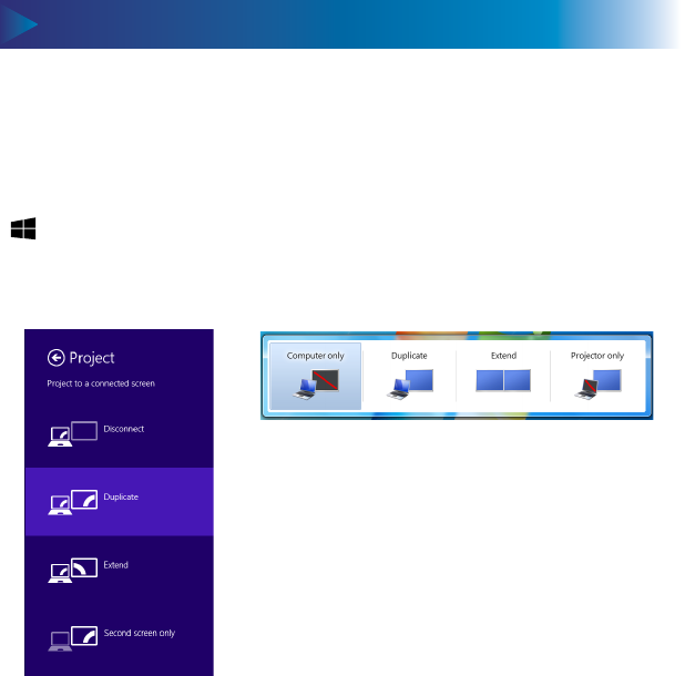
The Receiver supports three display modes when connected
with a compatible wireless display application (Intel WiDi or
Windows 8.1 Project, for example).
In Windows, press the Windows logo + P keys simultaneously
( + P) to launch the display options and select the desired
display mode from the options.
Windows 8.1 Windows 7
Switch Display Modes
The receiver’s local management console provides the ability
to manage the receiver’s settings.
Device Management
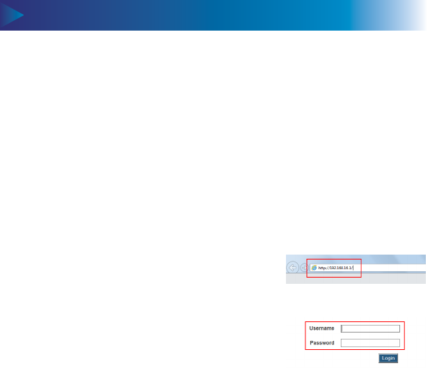
Log into the IT Management Console
When AGO is enabled (it is enabled by defualt), follow the
procedure below to log into the IT Management Console:
Step1 Connect your device to the receiver.
Step2 Access the URL address
(http://192.168.16.1) with a web brows-
er on your device.
Step3 The web server login interface
appears. Type the username and pass-
word in the Username and Password
boxes and click the Login button.
Note: You must connect your device to the receiver. Other-
wise, you cannot access the URL in Step 2.
Device Management (continued)
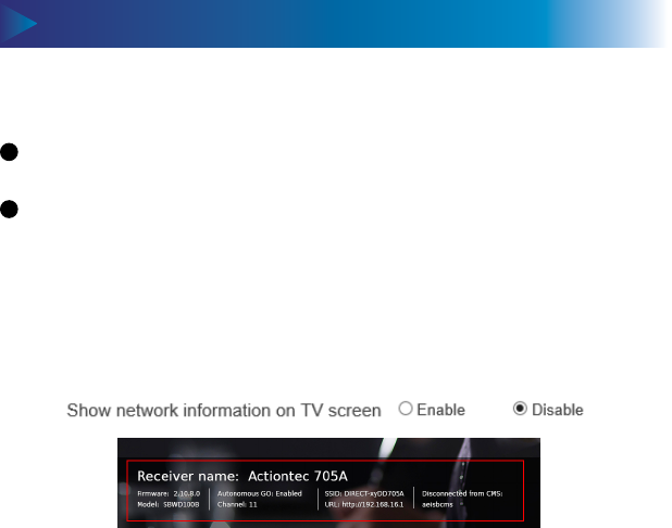
Note: By default, this feature is disabled. In this case, the net-
work information is not displayed.
Setting up Network Information Display on TV Screen
Step1 Go to the Network Settings tab page, and set the
Show network information on TV screen feature to Enable
or Disable.
Log into the IT Management Console (continued)
Note:
By default, the Username is “Administrator” and Password
is “WiDi”.
The username and password are case sensitive.
Step2 Click the “Apply” button to save your settings.
Device Management (continued) Device Management (continued)
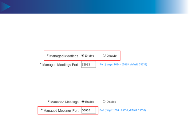
Setting up Managed Meetings
Step1Go to the Features tab page, and set the Managed
Meetings feature to Enable or Disable.
Step3 Click the “Apply” button to save your settings.
Step2 For better communication, you can dene a port
(Managed Meetings Port) for the Managed Meetings.
The Managed Meetings function allows meeting participants
to share the wireless display interactively, or allows the meet-
ing mediator to manage the display requests from the meet-
ing participants.
The Managed Meeting is available when AGO is enabled. And
it works with Intel Pro WiDi only.
Device Management (continued)
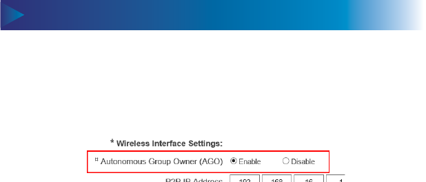
Setting up Autonomous Group Owner (AGO)
Step1 Go to the Network Settings tab page, and set the
Autonomous Group Owner (AGO) feature to Enable or
Disable.
Enable: The receiver will become the group owner of the
session. The communication channel can be dened by the
receiver. And the Managed Meetings feature is available.
Disable: The communication channel will be consistent with
the source device, or be determined through negotiation
between the receiver and the connecting device. And the
Managed Meetings feature is not available.
Step2 Click the “Apply” button to save your settings.
Step2 Click the “Apply” button to save your settings.
Device Management (continued)
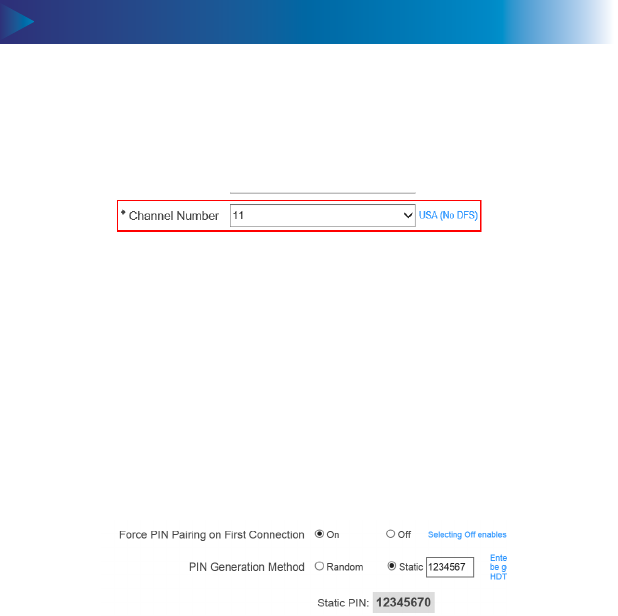
Setting up Communication Channel
Device Management (continued)
Step1 Go to the Network Settings tab page, and select a
desired communication channel from the Channel Number
box.
You should select a channel based on your network environ-
ment. Generally, cleaner channels (where less devices work)
will provide better performance. You can use Wi-Fi Analyzer to
help you identify a clean channel.
Setting up PIN Pairing Method
Step1Go to the Features tab page, and set the Force PIN
Pairing on First Connection feature to On or O.

Device Management (continued)
Select “O” to disable the PIN enforcement function. PIN
entry or PBC is required when connecting your device to
the receiver for the rst time.
Select “On” to enable the PIN enforcement function. In this
case, you must enter a PIN code on the device connecting
to the receiver for the rst time. When this function is en-
abled, the system provides two PIN generation methods:
Random and Static.
Random: A PIN code is generated randomly by the sys-
tem and displayed on the connected HDTV/projector.
Static: Users can enter seven (7) digits in the Static box,
then click the “Apply” button, and the system generates
an eight (8) digit PIN and display it on the Static PIN
eld. This PIN is not displayed on the connected HDTV/
projector.
Step2 Click the “Apply” button to save your settings.
Setting up PIN Pairing Method (continued)
Device Management (continued) Device Management (continued)
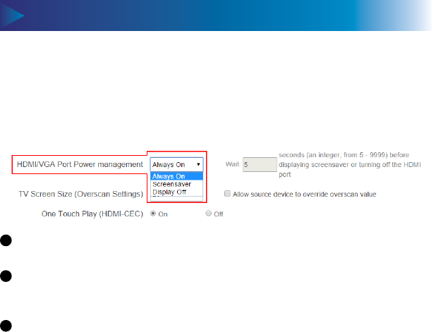
Always On: Selecting this option, the HDMI output is
always on.
Screensaver: Selecting this option, the system will run the
screensaver after the dened idle time expires. Users can
dene the idle time (5-9999 seconds) in the Wait time box.
HDMI O: Selecting this option, the HDMI output will be
turned o after the dened idle time expires. Users can
dene the idle time (5-9999 seconds) in the Wait time box.
Managing HDMI/VGA Port Output
Step1Go to the Features tab page, and select the desired
option in the HDMI/VGA Port Power management drop-
down box. There are three options: Always On, Screensaver,
and HDMI O.
Step2 Click the “Apply” button to save your settings.
Device Management (continued)
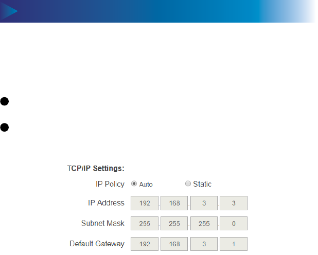
Setting up the Receiver’s TCP/IP Settings
Step1Go to the TCP/IP Setting section in the Remote Man-
agement tab page, and set the IP Policy to Auto or Static.
Step2 Click the “Apply” button to save your settings.
Auto: The receiver will be assigned an IP address by the
DHCP server.
Static: You can dene the IP address, subnet mask, and
default gateway for the receiver. If you select Static, you
need to dene a DNS server, too.
Device Management (continued) Device Management (continued)
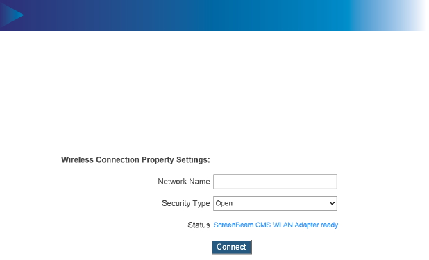
Setting up Wireless Connection Properties
Step1Go to the Wireless Connection Property Settings
section in the Remote Management tab page, and select a
desired Security Type and provide correct information for
relevant items.
Step2 Click the Connect button, and then the adapter will
connect to the wireless router (AP).
Note: Available security types are Open, Shared, WPA-PSK[T-
KIP], WPA2-PSK[AES], WPA-PSK[TKIP]+WPA2-PSK[AES], PEAP/
MSCHAPV2, and EAP-TLS.
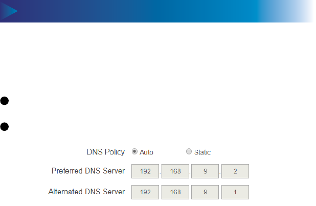
Device Management (continued)
Dening a DNS Server for the Receiver
Step1Go to the TCP/IP Setting section on the Remote Man-
agement tab page, and set the DNS Policy to Auto or Static.
Step2 Click the “Apply” button to save your settings.
Auto: The receiver will be assigned a DNS server automat-
ically.
Static: You can dene a DNS server for the receiver.
Device Management (continued) Device Management (continued)
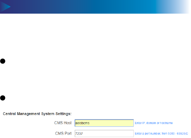
Dening a ScreenBeam CMS for the Receiver
Step1Go to the Central Management System Settings sec-
tion on the Remote Management tab page, and dene the
CMS Host and the CMS Port.
Step2 Click the “Apply” button to save your settings.
CMS Host: It is the IP address or the FQDN/hostname/
domain name/alias name (if you have properly congured
the DNS server and the DHCP server) of the server that
hosts the ScreenBeam CMS. It supports a domain with six
labels at most.
CMS Port: It is the port number for CMS communication.
FCC Information and Copyright
This equipment has been tested and found to comply with the limits for a Class B digital device,
pursuant to part 15 of the FCC Rules.
These limits are designed to provide reasonable protection against harmful interference in a residential
installation. This equipment generates,
uses and can radiate radio frequency energy and, if not installed and used in accordance with the
instructions, may cause harmful interference
to radio communications. However, there is no guarantee that interference will not occur in a particular
installation. If this equipment does
cause harmful interference to radio or television reception, which can be determined by turning the
equipment off and on, the user is
encouraged to try to correct the interference by one or more of the following measures:
—Reorient or relocate the receiving antenna.
—Increase the separation between the equipment and receiver.
—Connect the equipment into an outlet on a circuit different from that to which the receiver is
connected.
—Consult the dealer or an experienced radio/TV technician for help.
This device complies with part 15 of the FCC Rules. Operation is subject to the
following two conditions:
(1)This device may not cause harmful interference, and
(2) this device must accept any interference received, including interference that may
cause undesired operation.
changes or modifications not expressly approved by the party responsible for compliance could
void the user's authority to operate the equipment.
This equipment complies with FCC radiation exposure limits set forth for an uncontrolled
environment .This equipment should be installed and operated with minimum distance 20cm
between the radiator& your body. This transmitter must not be co-located or operating in
conjunction with any other antenna or transmitter.

IC warning
This device complies with Industry Canada licence-exempt RSS standard(s).
Operation is subject to the following two conditions: (1) This device may not cause
interference, and (2) This device must accept any interference, including interference
that may cause undesired operation of the device.
Le présent appareil est conforme aux CNR d'Industrie Canada applicables aux
appareils radio exempts de licence. L'exploitation est autorisée aux deux conditions
suivantes:
(1) l'appareil ne doit pas produire de brouillage, et
(2) l'utilisateur de l'appareil doit accepter tout brouillage radioélectrique subi, même si
le brouillage est susceptible d'en compromettre le fonctionnement
changes or modifications not expressly approved by the party responsible for compliance could
void the user's authority to operate the equipment.
This equipment complies with FCC radiation exposure limits set forth for an uncontrolled
environment .This equipment should be installed and operated with minimum distance 20cm
between the radiator& your body. This transmitter must not be co-located or operating in
conjunction with any other antenna or transmitter