Actwell Technology ACT-203TX Wireless Control Security/Alarm Transmitter Camera User Manual Part 1
Actwell Technology Inc. Wireless Control Security/Alarm Transmitter Camera Users Manual Part 1
Contents
- 1. Users Manual Part 1
- 2. Users Manual Part 2
Users Manual Part 1

~,
Fe CEO681(i) I
...
Edition
First edition, September 2004
Copyright information
',\
This publication, including all photographs, illustrations and software, is
protected under international copyright laws, with all rights reserved. Neither this
manual, nor any of the material contained herein, may be reproduced without
written consent of the author.
.~.\
.~ @ September, 2004
'-< .
Trademarks
All product names used in this manual are the properties of their respective
owners and are acknowledged.
'>""::
..
-
Safety and battery use
.Read and follow any warnings in this manual.
.Read the regulatory compliance notice on page 22.
When not in use, remove any batteries and store them in a cool dry place.
.
.Do not use the camera in temperatures below -10 or exceeding 55 degrees
Celsius
.Don't dispose of used batteries with household waste. Return the batteries to
your dealer or to a special disposal service.
Any servicing must only be done by qualified personnel.
.
.Do not set up or use the receiver or camera in a wet or damp environment.
Save these instructions for future reference.
.
About this manual
This manual is designed to assist users with setting up and operating #ACT-203TX
/#ACT-205TX 2.4GHz wireless remote security alarm camera system.
Information in this document has been carefully checked for accuracy; however,
no guarantee is given as to the correctness of the contents. The information
contained in this document is subject to change without notice.
11

Table of contents
I-GETTING STARTED 1
CHECKINGTHEPACKINGLIST 1
IDENTIFYINGPARTS 3
Camera 3
Receiver 4
2-SETTIN G UP :""""""""""""""""" 5
PRE-SETUPTESTING 5
MAKINGCONNECTIONS 6
Receiver setup 6
Connecting the AC adapter to the camera 7
Connecting the battery to the camera 7
MOUNTINGOPTIONS 8
Ceiling installation 8
Wall installation 9
Hidden installation 12
ADJUSTING THE CAMERA ANGLE 14
3-0PERATION 15
OPERATING RESTRICTIONS ,15
MATCHINGCHANNELS 16
STANDARD ALWAYS-ONOPERATION " 16
REED SWITCH OPERATION """""""""""""""""""""""""""""'" 17
Reed switch installation 17
Set to NO (Normal Open) 17
Set to NC (Normal Closed) 17
R/C CABLEOPERATION ,18
SWITCHINGAUDIOOUTPUT 18
iii

APPENDIX ..19
CLEANING ,19
TROUBLESHOOTING ,19
TECHNICAL SPECIFICATIONS 21
Camera 21
Receiver 21
FEDERAL COMMUNICATIONS COMMISSION (FCC) STATEMENT 22
WARRANTY , ' 23
IV
1-Getting started
Congratulations on your purchase of the remote camera. Use this camera to monitor
locations wirelessly, as a stand-alone solution or integrated into an existing alarm
system.
Checking the packing list
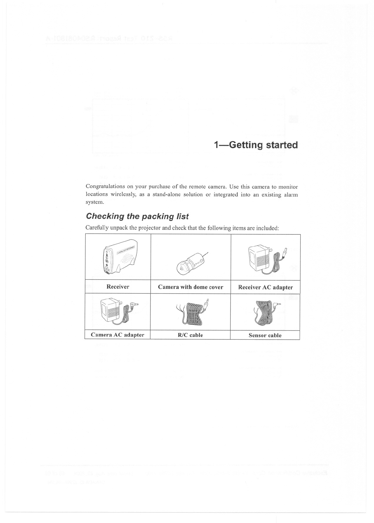
Carefully unpack the projector and check that the following items are included:
$i
Receiver Camera with dome cover Receiver AC adapter
Camera AC adapter RlC cable Sensor cable
--
I-GETTING STARTED
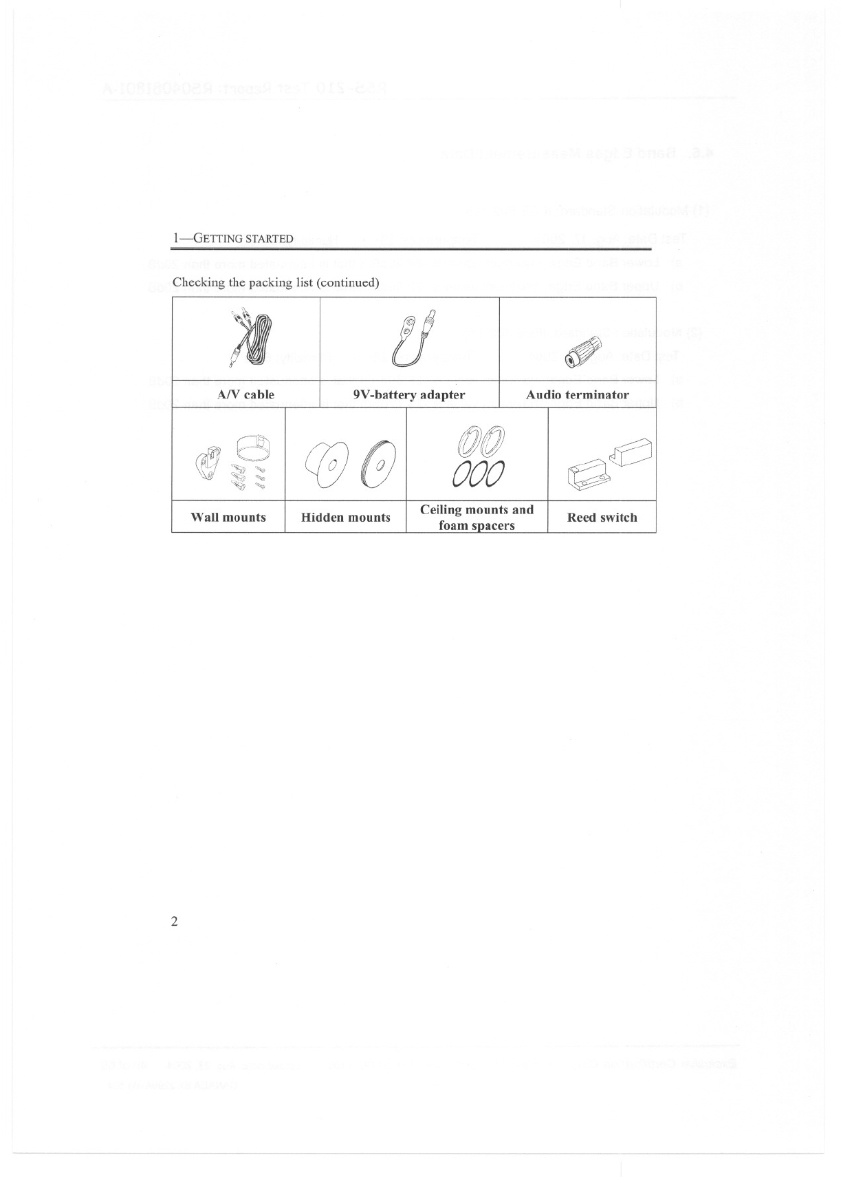
Checking the packing list (continued)
A/V cable
Wall mounts
2
@
tJ
..<t ,;";,,
ff)
9V-battery adapter
Hidden mounts
!f
.
~n)/f})
~/Iil#
000
Ceiling mounts and
foam spacers
(11
.,4
.
"
.
~
7"
.~
Audio terminator
~I~
~
Reed switch
IDENTIFYING PARTS
Identifying parts
Camera
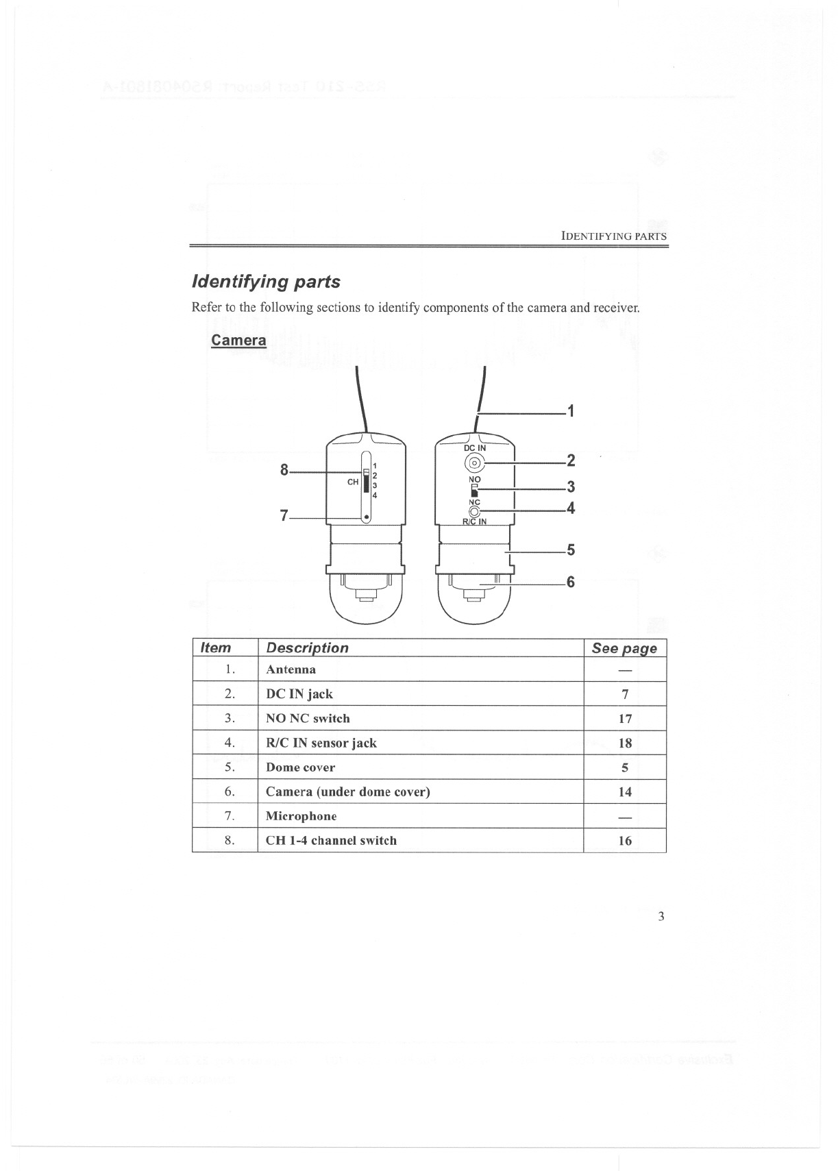
Refer to the following sections to identify components of the camera and receiver.
81
CHili;4
7.
J1
2
3
4
5
6
3
Item Description See page
1. Antenna -
2. DC IN jack 7
3. NO NC switch 17
4. R/C IN sensor jack 18
5. Dome cover 5
6. Camera (under dome cover) 14
7. Microphone -
8. CH 1-4 channel switch 16
I-GETTING STARTED
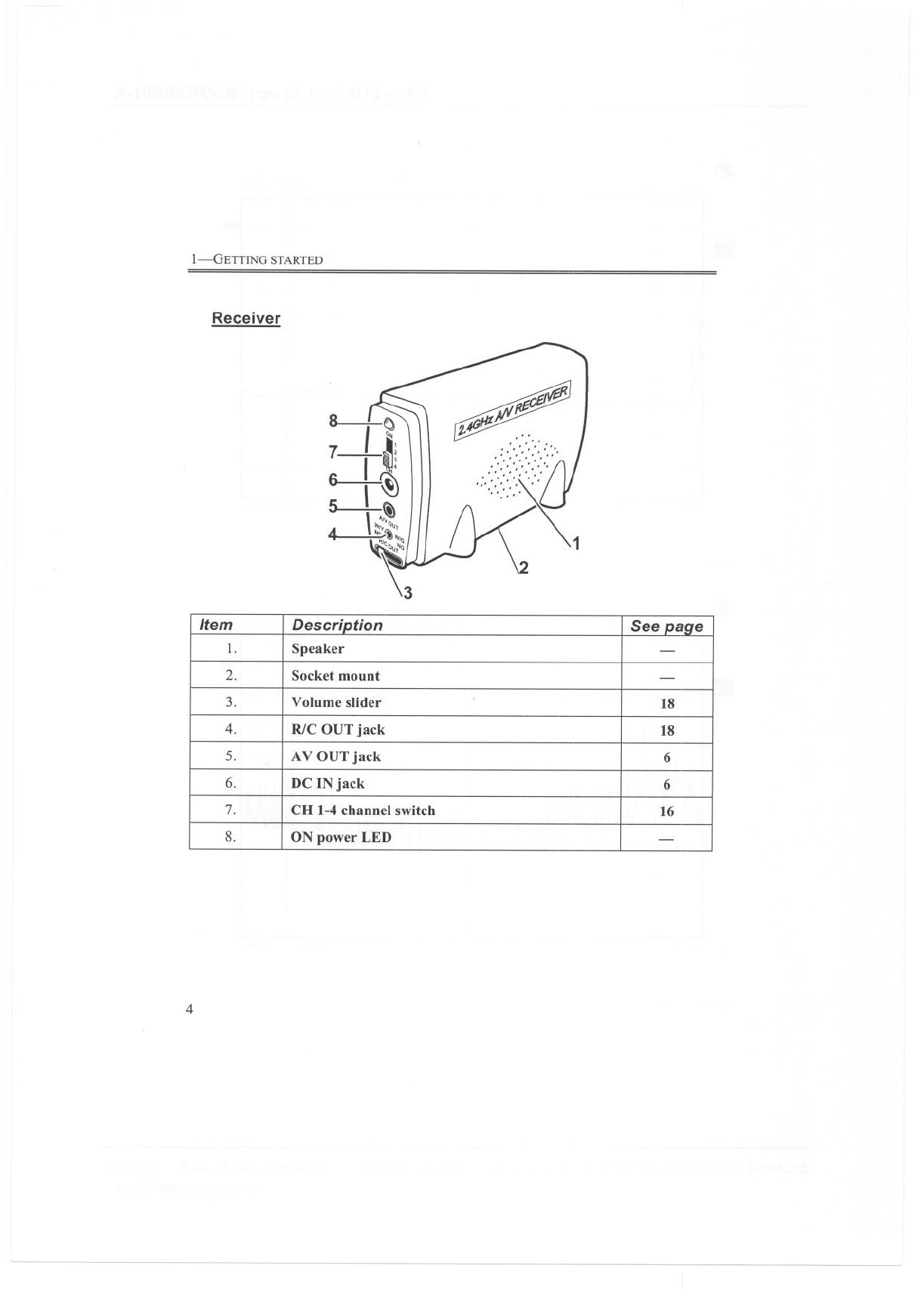
Receiver
~Mcif@!J
t4GJI1-f'I~."
':':/:::' ~
'::::':
IJ
':/:'
..::.,
/"
1
4
Item Description See paqe
1. Speaker -
2. Socket mount -
3. Volume slider 18
4. R/C OUT jack 18
5. AV OUT jack 6
-
6. DC IN jack 6
7. CH 1-4 channel switch 16
8. ON power LED -
2-Setting up
This section explains the mounting options and setup of the remote camera. However,
before installing the camera check that all the parts are working as described below.
Pre-setup testing
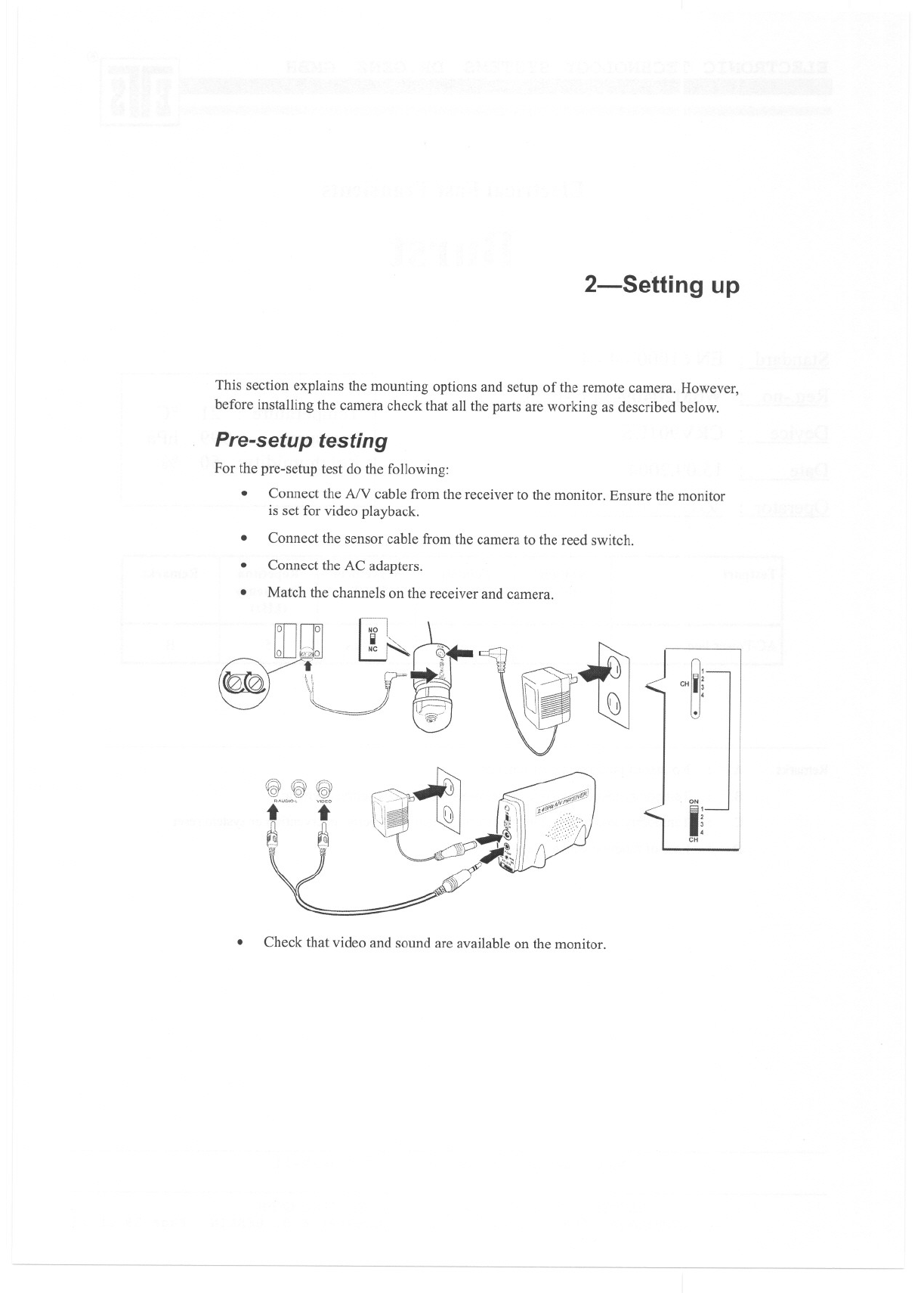
For the pre-setup test do the following:
.Connect the AN cable from the receiver to the monitor. Ensure the monitor
is set for video playback.
Connect the sensor cable from the camera to the reed switch.
.
.Connect the AC adapters.
Match the channels on the receiver and camera.
.
'~ ~
:
.
CH 3
4
.
r?\\'251 "'j]
f& \(g \(GY
."",°' i
[\ J1
~~J
1;1 f"
I~
CH
.Check that video and sound are available on the monitor.
2-SETTING UP
.Test the sensor operation by moving the reed switch apart and changing the
NO NC setting on the camera.
If some functions do not work, check the corresponding section in this
manual before installing the camera.
.
Making connections
The receiver is designed to connect to different devices such as a TV, VCR, or digital
video recorder (DVR).
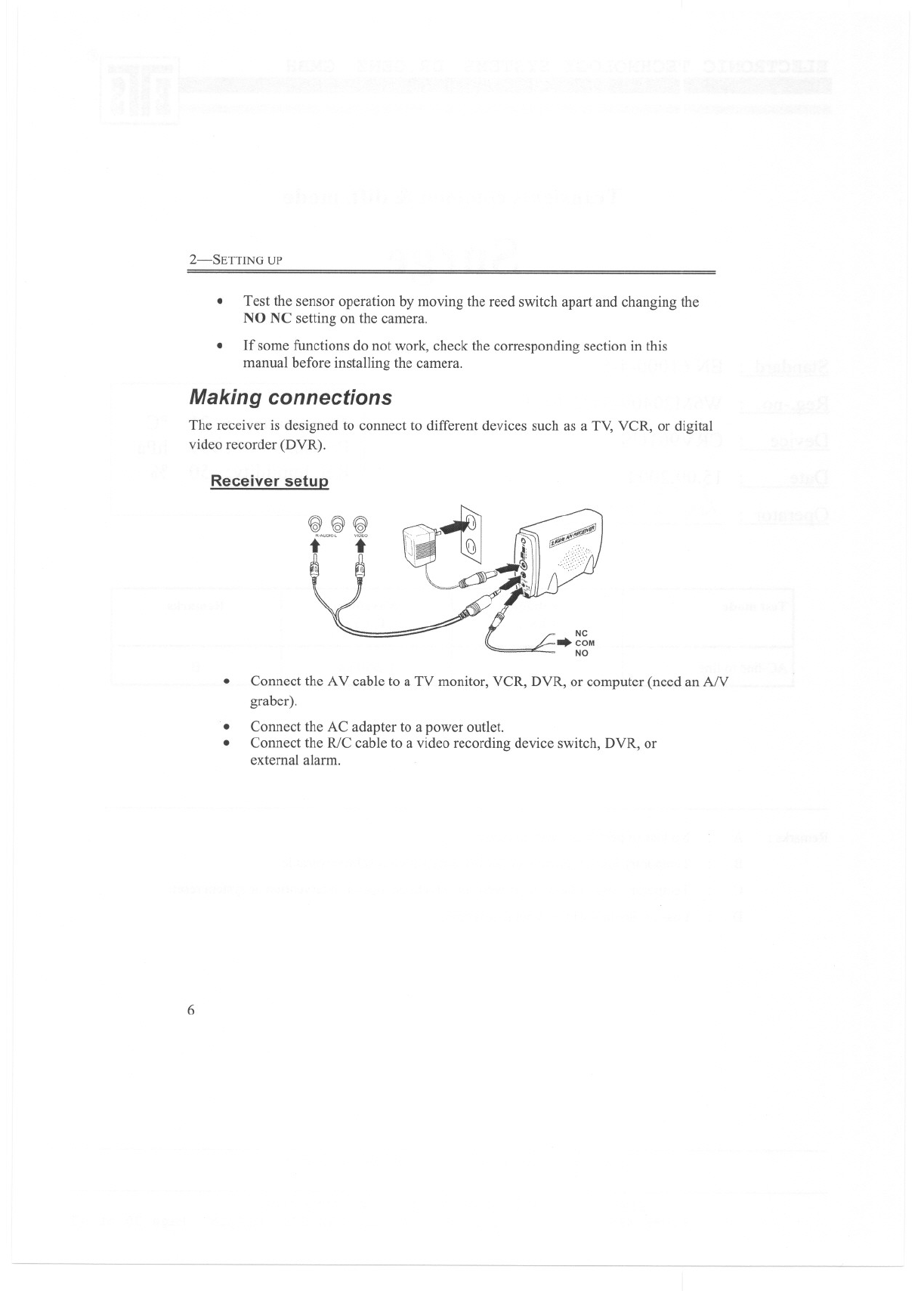
Receiver setuQ
~~~
twO'" i
.Connect the AV cable to a TV monitor, VCR, DVR, or computer (need an AN
graber).
Connect the AC adapter to a power outlet.
Connect the R/C cable to a video recording device switch, DVR, or
external alarm.
.
.
6
MAKING CONNECTIONS
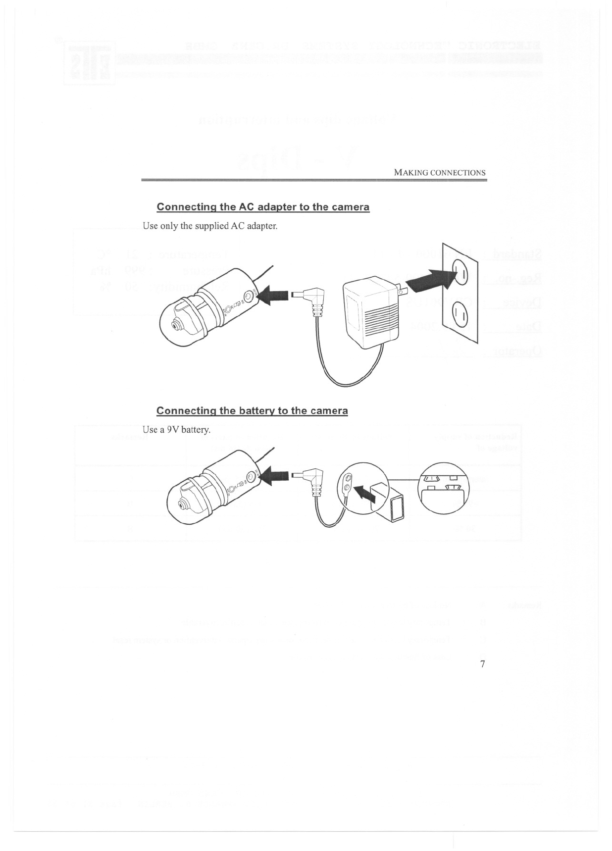
Connectina the AC adapter to the camera
Use only the supplied AC adapter.
Connectina the battery to the camera
Use a 9V battery.
7
2-SETTING UP
Mounting options
Using the supplied accessories, the camera can be mounted on a ceiling or wall. It can
also be mounted in a hidden location such as in a container or behind a partition.
Important: The dome cover holds the camera housing together. When you
remove the dome cover, take care that the camera housing does
not separate.
Ceiling installation
Before choosing a location for the ceiling installation, consider the following:
.You may need to install the camera from above, in which case two adjacent
tiles need to be removed for the installation.
.You must hold the camera in position from above the ceiling tile while
screwing the dome cover on.
You may need to adjust the camera angle before replacing the adjacent tile.
.
.You need a power source for the camera.
Refer to the following for the ceiling installation.
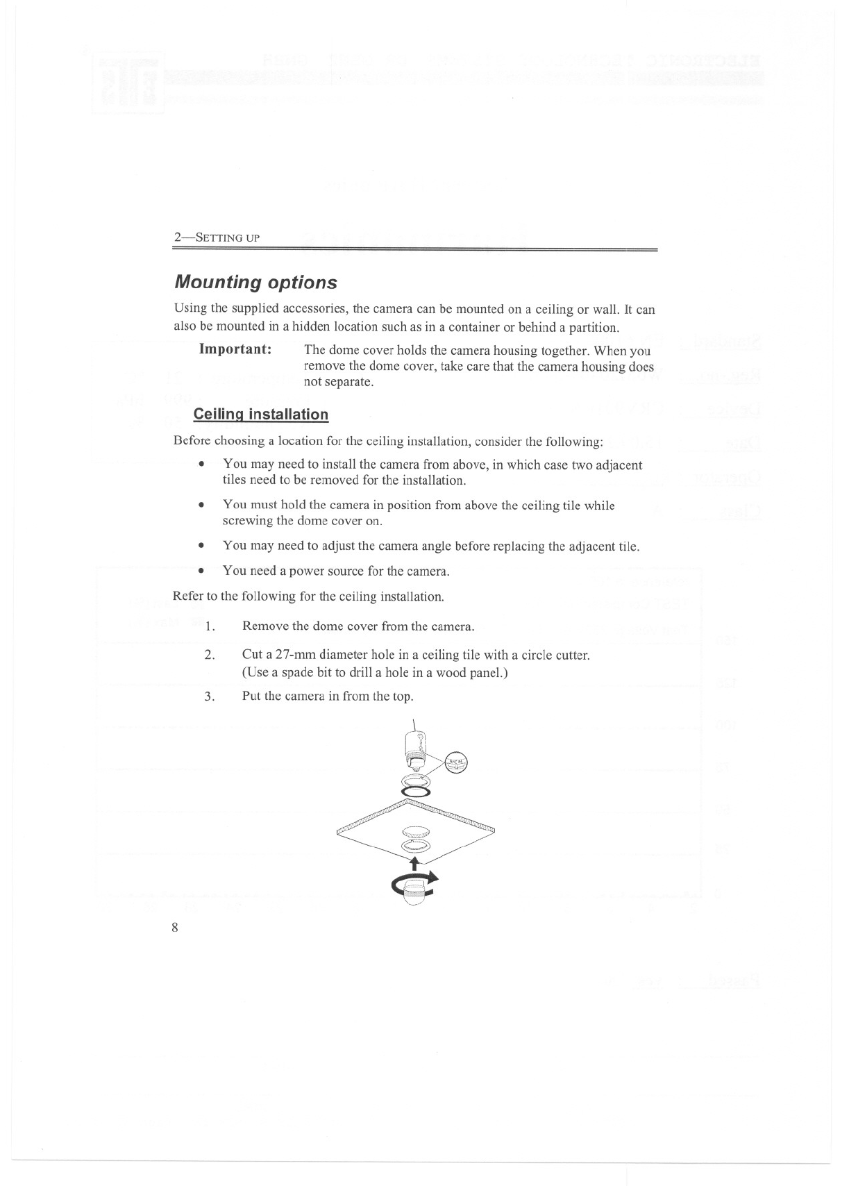
1. Remove the dome cover from the camera.
2. Cut a 27-mm diameter hole in a ceiling tile with a circle cutter.
(Use a spade bit to drill a hole in a wood panel.)
Put the camera in from the top.
3.
rt
l'91
;~1i
~";Q
8~
<e:
8
MOUNTING OPTIONS
4. Use foam spacers to ensure the dome cover screws on securely.A
thinner ceiling tile may require more than one foam ring; a thicker
ceiling tile may require none at all.
Adjust the camera angle. (See "Adjusting the camera angle" on
page 14.)
5.
6. Screw the dome cover onto the camera.
Wall installation
Before choosing a location for the wall installation, consider the following:
.You need a power source for the camera. Check that the cable length on the
supplied AC adapter is long enough to reach your power source before
drilling holes.
.Does the location you choose to install the camera allow easy access to the
camera? The camera dome must be removed and the camera taken out of the
wall bracket to connect to DC IN and R/C IN.
The wall bracket is designed so that cables cannot be unplugged from the
camera once installed. However, if you need to access the DC IN and R/C
IN jacks often, consider fixing a block of wood behind the bracket so there is
more space between the jacks and the wall.
.
1. Remove the dome cover from the camera.
2. Put the wall mount ring on the camera.
The wall mount ring and camera are keyed to connect only one way.
9
2-SETTING UP
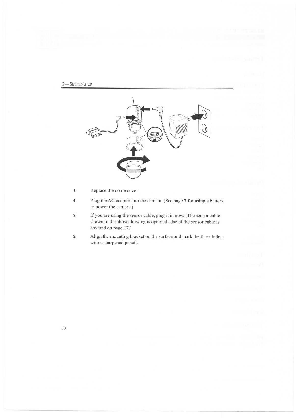
3. Replace the dome cover.
5.
Plug the AC adapter into the camera. (See page 7 for using a battery
to power the camera.)
If you are using the sensor cable, plug it in now. (The sensor cable
shown in the above drawing is optional. Use of the sensor cable is
covered on page 17.)
4.
6. Align the mounting bracket on the surface and mark the three holes
with a sharpened pencil.
10