Acuity Lighting DTL01 Bluetooth enabled remote User Manual
Acuity Brands Lighting, Inc. Bluetooth enabled remote
User Manual

DTL – A Division of Acuity Brands Lighting Inc.
DTL01/DTL02 User’s Manual
THIS DOCUMENT IS DTL PROPRIETARY Page 1/11
DTL01 and DTL02User’s Manual

DTL – A Division of Acuity Brands Lighting Inc.
DTL01/DTL02 User’s Manual
THIS DOCUMENT IS DTL PROPRIETARY Page 2/11
Table of Contents
Background ................................................................................................................................................... 3
Overview of Radio Module Hardware .......................................................................................................... 4
Theory of Operation...................................................................................................................................... 5
Pin-out Chart for the DTL01 ....................................................................... Error! Bookmark not defined.
Operation of the DTL01 Radio Modem ......................................................................................................... 5
Operation of the DTL02 Radio Modem ......................................................................................................... 6
Command Set ................................................................................................................................................ 6
RF Exposure Limit Warning ........................................................................................................................... 8
FCC Certification Requirements .................................................................................................................... 8
Warning (Part 15.21) ..................................................................................................................................... 8
Compliance Statement (Industry Canada) .................................................................................................... 9
Example Applications .................................................................................................................................. 10
Installation .................................................................................................................................................. 10
Host Manufacturer Statements .................................................................................................................. 10
Host Labeling ............................................................................................................................................... 11

DTL – A Division of Acuity Brands Lighting Inc.
DTL01/DTL02 User’s Manual
THIS DOCUMENT IS DTL PROPRIETARY Page 3/11
Background
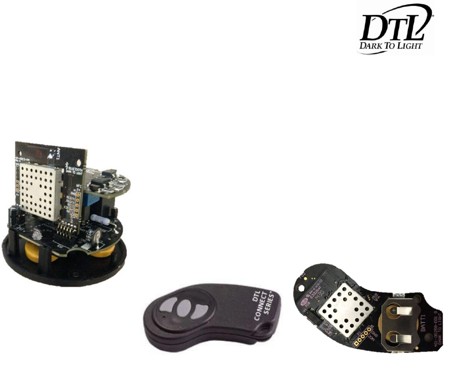
The DTL01 radio module is intended for installation in Bluetooth streetlight controls applications and to
communicate to keyfobDTL02. The module is supplied regulated 3.3Vdc by a DTL custom host board
with +/-1% regulated supply in all applications. The keyfob is supplied by 3V coin cell CR2032.
The module assembly DTL01is also known as ROAM part numbers; 401-00213-001
The keyfob assembly DTL02is also known as DTL part number; 401-00258-001
FIGURE REMOVED TO KEEP CONFIDENTIALITY
KeyFobDTL02
PCB#: 401-00258-001
FIGURE REMOVED TO KEEP CONFIDENTIALITY
Radio Module DTL01
PCB#: 401-00213-001
DTL – A Division of Acuity Brands Lighting Inc.
DTL01/DTL02 User’s Manual
THIS DOCUMENT IS DTL PROPRIETARY Page 4/11
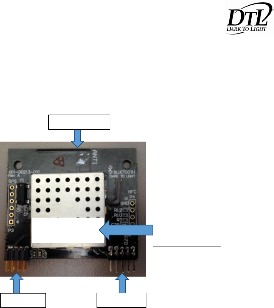
Overview of Radio Module Hardware
The DTL01 and DTL02 are Bluetooth modules emitting GFSK 2.4GHz on the ISM band. The features are
outlined below. FCC ID label will be applied as shown. Only the following antenna gain and type have
been approved for use with these products: 2 dBi gain, PIFA antenna.
FCC ID: 2ADCB-DTL01
IC: 6715C-DTL01
2dBi PIFA Antenna
Shield (FCC/IC label
placed here)
P1 (pins 1-8)
P2 (pins 1-10)
DTL – A Division of Acuity Brands Lighting Inc.
DTL01/DTL02 User’s Manual
THIS DOCUMENT IS DTL PROPRIETARY Page 5/11
Theory of Operation
THIS SECTION REMOVED TO KEEP CONFIDENTIALITY
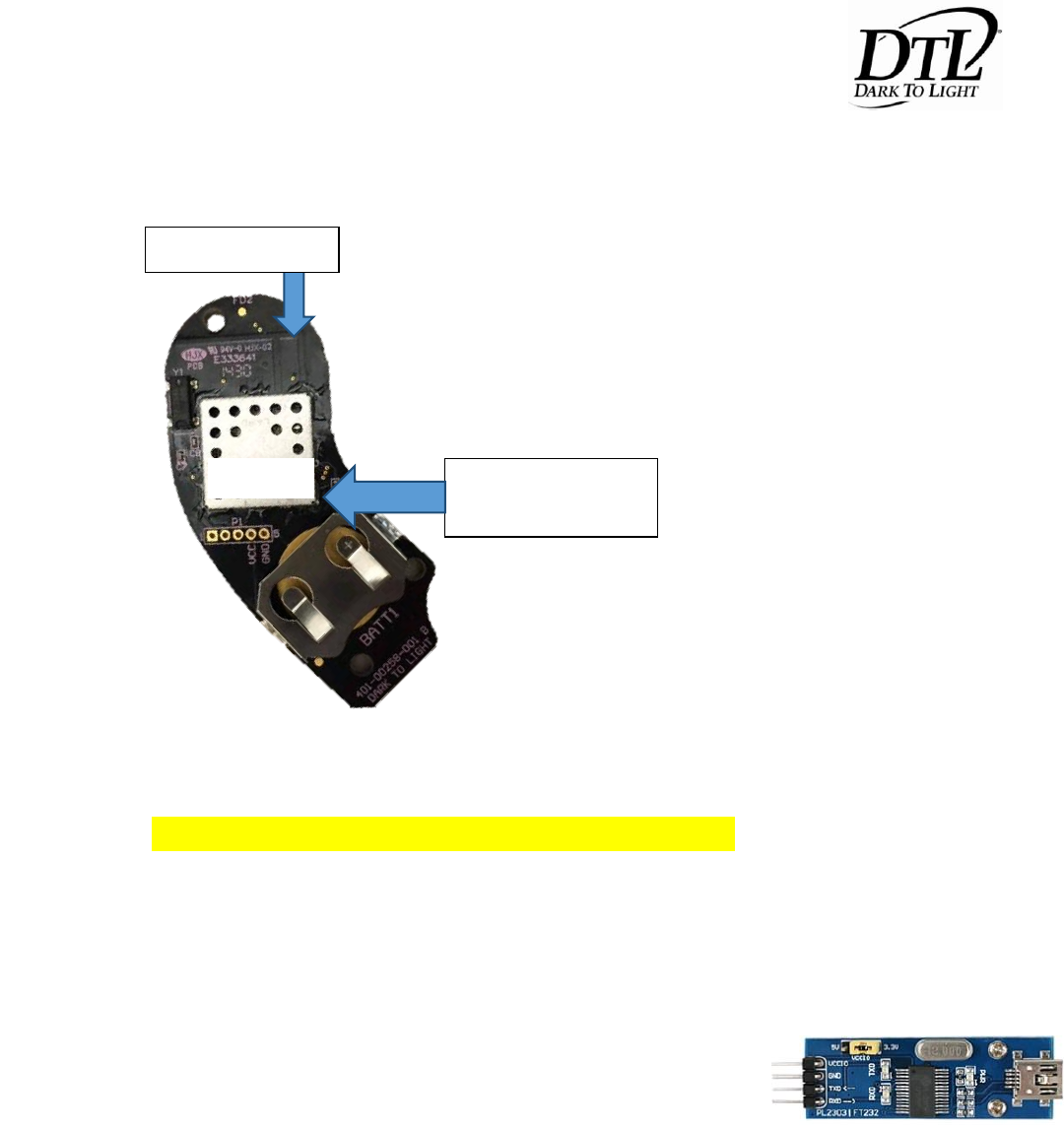
Operation of the DTL01 Radio Modem
Communication with the DTL01 radio modem happens through UART 1. The baud rate is set to 115000,
8N1. Communications through P7 pin 8 (Tx) and pin 10 (Rx). Power
through P1 pin 2 (GND) and pin 8 (Vcc). All 4 lines go through USB to
UART converter (PL-2303HX) from Mini.
NOTE: In order for the CC2541 to enter production test mode to handle HCI commands, you must
connect P7 pin 5 (CTS) to GND as shown below.
FCC ID: 2ADCB-DTL02
IC: 6715C-DTL02
2dBi PIFA Antenna
Shield (FCC/IC label
placed here)
DTL – A Division of Acuity Brands Lighting Inc.
DTL01/DTL02 User’s Manual
THIS DOCUMENT IS DTL PROPRIETARY Page 6/11
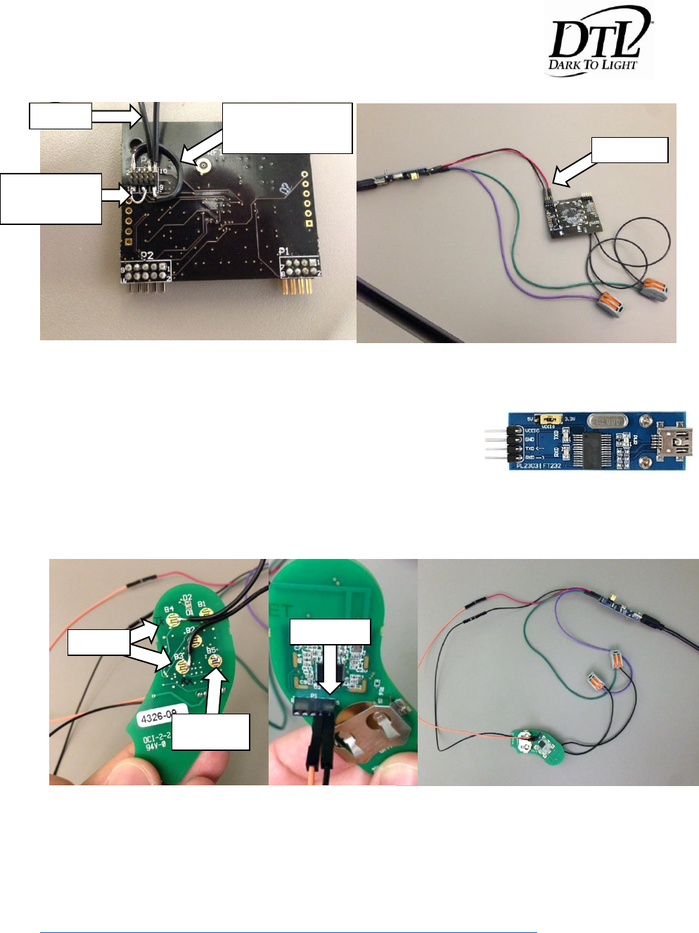
Operation of the DTL02 Radio Modem
Communication with the DTL02 radio modem happens through UART 1. The baud rate is set to 115000,
8N1. Communications through B4 (Tx) and B3 (Rx). Power is
supplied through P1 pin 4 (Vcc) and pin 5 (Gnd). Again all 4 lines go
through USB to UART converter (PL-2303HX) from Mini.
NOTE: In order for the CC2541 to enter production test mode to handle HCI commands, you must
connect B5 (CTS) to GND as shown below.
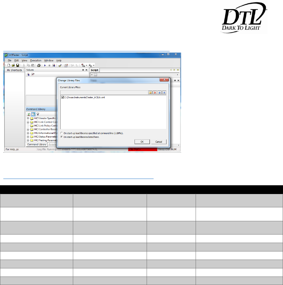
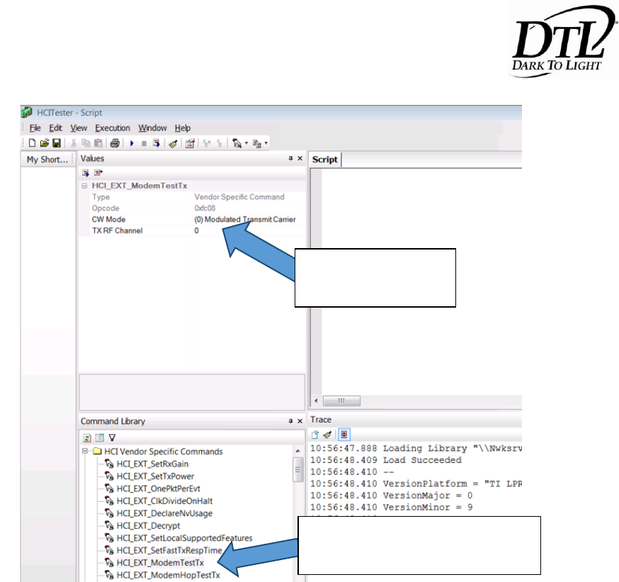
Command Set
Open an instance of “HCI Tester” and verify that the serial port are the correct settings as shown above.
You can download the HCI tester at:
http://e2e.ti.com/support/wireless_connectivity/m/videos__files/623388.aspx
Then install the XML files needed for the HCI commands on BLE.
Jumper required to
enter production
test mode
TX and RX
Jumper required for JTAG
programming and debug –
unrelated to FCC testing
VCC and GND
TX and RX
Solder bridge
B5 to GND
VCC and GND
DTL – A Division of Acuity Brands Lighting Inc.
DTL01/DTL02 User’s Manual
THIS DOCUMENT IS DTL PROPRIETARY Page 7/11
http://processors.wiki.ti.com/index.php/LPRF_BLE_HCITester
Once the program can connect with the radio UART, the FCC tests that will need to be run are listed at:
http://processors.wiki.ti.com/index.php/FCC_ETSI_Test
Command
CW Mode
RF Channel
Description
HCI_EXT_ModemTestTx
Unmodulated
0
TX Continuous Wave (CW), 2402
MHz, 0 dBm
HCI_EXT_ModemTestTx
Unmodulated
19
TX Continuous Wave (CW), 2440
MHz, 0 dBm
HCI_EXT_ModemTestTx
Unmodulated
39
TX Continuous Wave (CW), 2480
MHz, 0 dBm
HCI_EXT_ModemTestTx
Modulated
0
TX Modulated, 2402 MHz 0 dBm
HCI_EXT_ModemTestTx
Modulated
19
TX Modulated, 2440 MHz 0 dBm
HCI_EXT_ModemTestTx
Modulated
39
TX Modulated, 2480 MHz 0 dBm
HCI_EXT_ModemTestRx
N/A
0
RX On, 2402 MHz Standard gain
HCI_EXT_ModemTestRx
N/A
19
RX On, 2440 MHz Standard gain
HCI_EXT_ModemTestRx
N/A
39
RX On, 2480 MHz Standard gain
Note that between each test the user may need to execute “HCI_EXT_EndModemTest”.
DTL – A Division of Acuity Brands Lighting Inc.
DTL01/DTL02 User’s Manual
THIS DOCUMENT IS DTL PROPRIETARY Page 8/11
RF Exposure Limit Warning
TBD
FCC Certification Requirements
This device complies with Part 15 of the FCC rules. Operation is subject to the following two conditions:
1. This device may not cause harmful interference, and
2. This device must accept any interference received, including interference that may cause undesired
operation.
Warning (Part 15.21)
Changes or modifications not expressly approved by the party responsible for compliance could void the
user’s authority to operate the equipment.
Where to change CW
Mode or Channel
Click once to view/change options
or double click to execute.

DTL – A Division of Acuity Brands Lighting Inc.
DTL01/DTL02 User’s Manual
THIS DOCUMENT IS DTL PROPRIETARY Page 9/11
Compliance Statement (Industry Canada)
IC – CanadaThis device complies with Industry Canada license-exempt RSS standard(s). Operation is
subject to the following two conditions:
(1) this device may not cause interference, and (2) this device must accept any interference, including
interference that may causeundesired operation of the device.
Le présentappareilestconforme aux CNR d’Industrie Canada applicablesauxappareils radio exempts de
licence.L’exploitationestautorisée aux deux conditions suivantes :
(1) l’appareilnedoit pas produire de brouillage, et (2)l’utilisateur de l’appareildoit accepter tout
brouillage radio électriquesubi, mêmesi le brouillageest susceptible d’encompromettre le
fonctionnement.
DTL – A Division of Acuity Brands Lighting Inc.
DTL01/DTL02 User’s Manual
THIS DOCUMENT IS DTL PROPRIETARY Page 10/11
Example Applications
Picture of typical application of the DTL01 Module:
The DCC127 series photocontrol will use this DTL01bluetooth board in
order to communicate to the keyfobDTL02.
The DCR remote key fob uses the DTL02bluetooth radio to communicate to the DCC127 series
photocontrol.
Installation
The DTL01 module is limited to OEM installation only. OEM integrators may not provide instruction for
end user to remove/install module.
Host Manufacturer Statements
To ensure compliance with all non-transmitter functions the host manufacturer (DTL/Acuity Brands
Lighting, Inc.) is responsible for ensuring compliance with the module(s) installed and fully operational.
For example, if a host was previously authorized as an unintentional radiator under the Declaration of
Conformity procedure without a transmitter certified module and a module is added, the host
manufacturer is responsible for ensuring that the after the module is installed and operational the host
continues to be compliant with the Part 15B unintentional radiator requirements. Since this may depend
on the details of how the module is integrated with the host, the grantee (the party responsible for the
module grant) shall provide guidance to the host manufacturer for compliance with the Part 15B
requirements.
DTL – A Division of Acuity Brands Lighting Inc.
DTL01/DTL02 User’s Manual
THIS DOCUMENT IS DTL PROPRIETARY Page 11/11
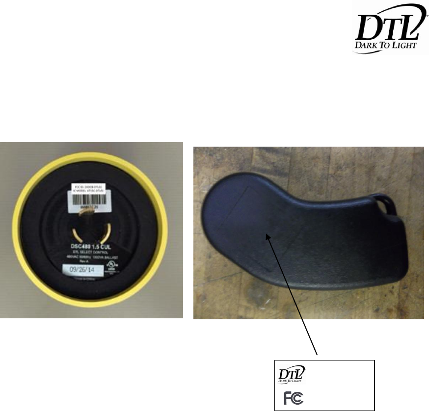
Host Labeling
The following are pictures and locations of the device labels.
Underside of control
Backside of key fob
CONNECT SERIES
Model: DTL02
FCC ID: 2ADCB-DTL02
IC: 6715C-DTL02