Adcon Telemetry A840 Telemetry Gateway User Manual Base Station A840 440
Adcon Telemetry Inc Telemetry Gateway Base Station A840 440
UserManual.wiki
>
Adcon Telemetry
>
A840 User Manual
Users manual
Navigation menu
Upload a User Manual
Namespaces
Wiki Guide
HTML
PDF
Info
Views
User Manual
Discussion / Help
Navigation


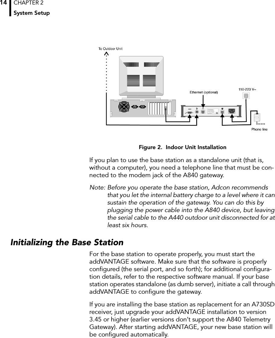
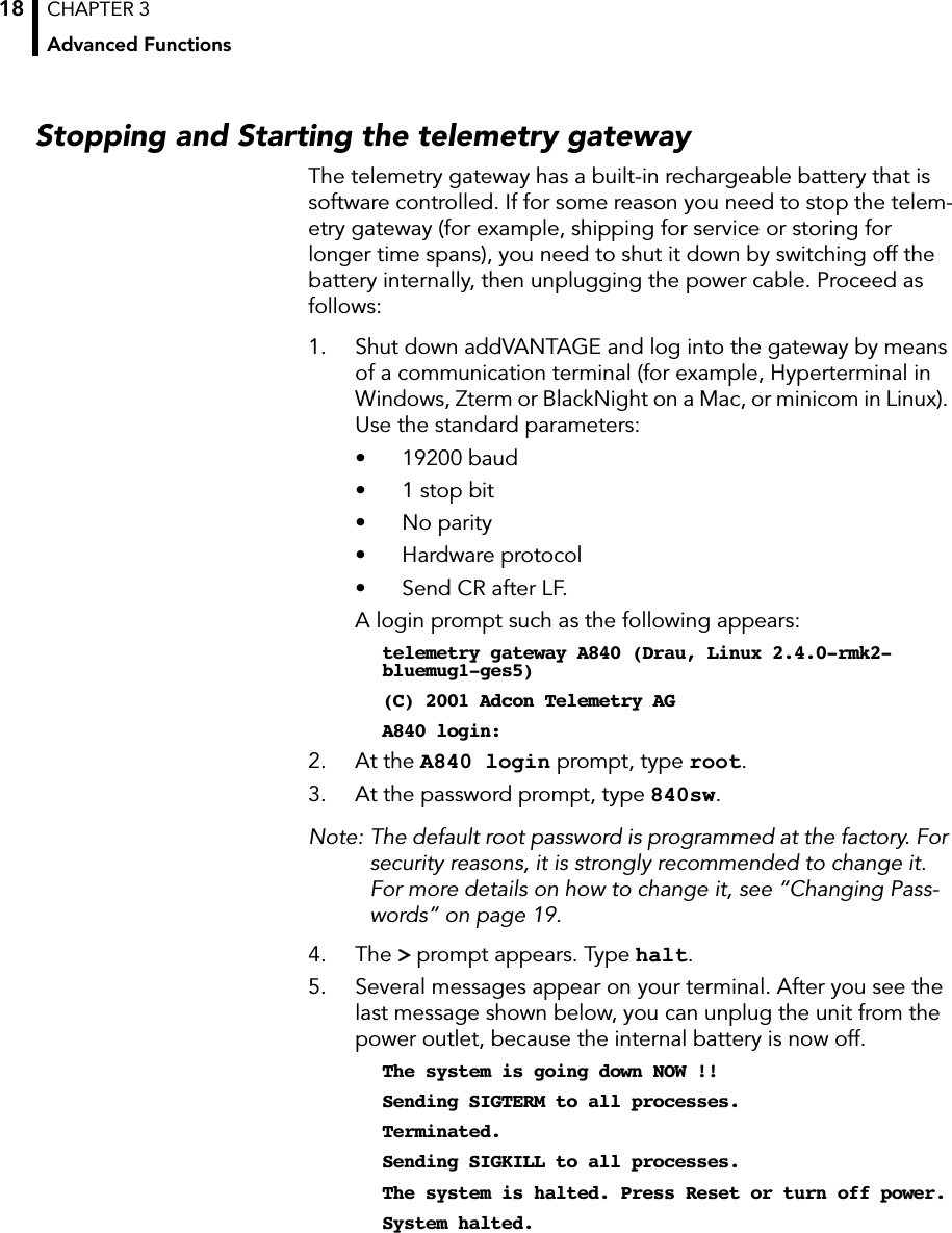
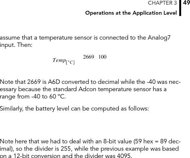
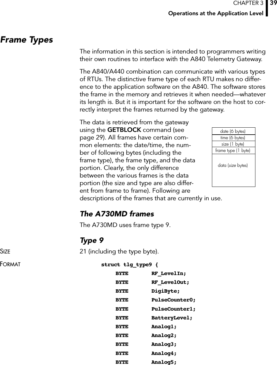
![CHAPTER 3Administrative Tasks at the System Level19To start the unit, plug the mains cable into the power outlet. After the boot procedure finishes (which takes about 20 seconds), the unit is fully operational.Changing PasswordsFor security reasons you might want to change the password of your gateway. The unit comes from the factory with only two users: root and adv. The root user is intended only for administrative tasks, while adv is used by the addVANTAGE software. The pass-word for root is 840sw and for adv it is addvantage. You can change either password, but if you do so, be sure to keep the new passwords in a secure location.Complete the following steps to change the root password:1. Log into the gateway as root, as described in the first step of “Stopping and Starting the telemetry gateway” on page 18.2. At the login prompt, type passwd.3. The system prompts you to enter a new password:Changing password for root.Enter the new password (minimum of 5, maximum of 8 characters).Please use a combination of upper and lower case let-ters and numbers.Enter new password:4. After you enter the new password, the system prompts you to reenter it to be sure that you didn’t mistype it. Reenter the password:Re-enter new password:Password changed.To change the password for the user adv, the steps are the same, except that you start with:passwd advIf you do change the password for the user adv, you must also change it in addVANTAGE. To do this, edit the agroexp.ini file. Find the section [Communication], which has the following entries:User=advPassword=addvantageDo not change the user name, but type whatever new password you assigned to the adv user. The two password strings in the](https://usermanual.wiki/Adcon-Telemetry/A840/User-Guide-221017-Page-19.png)
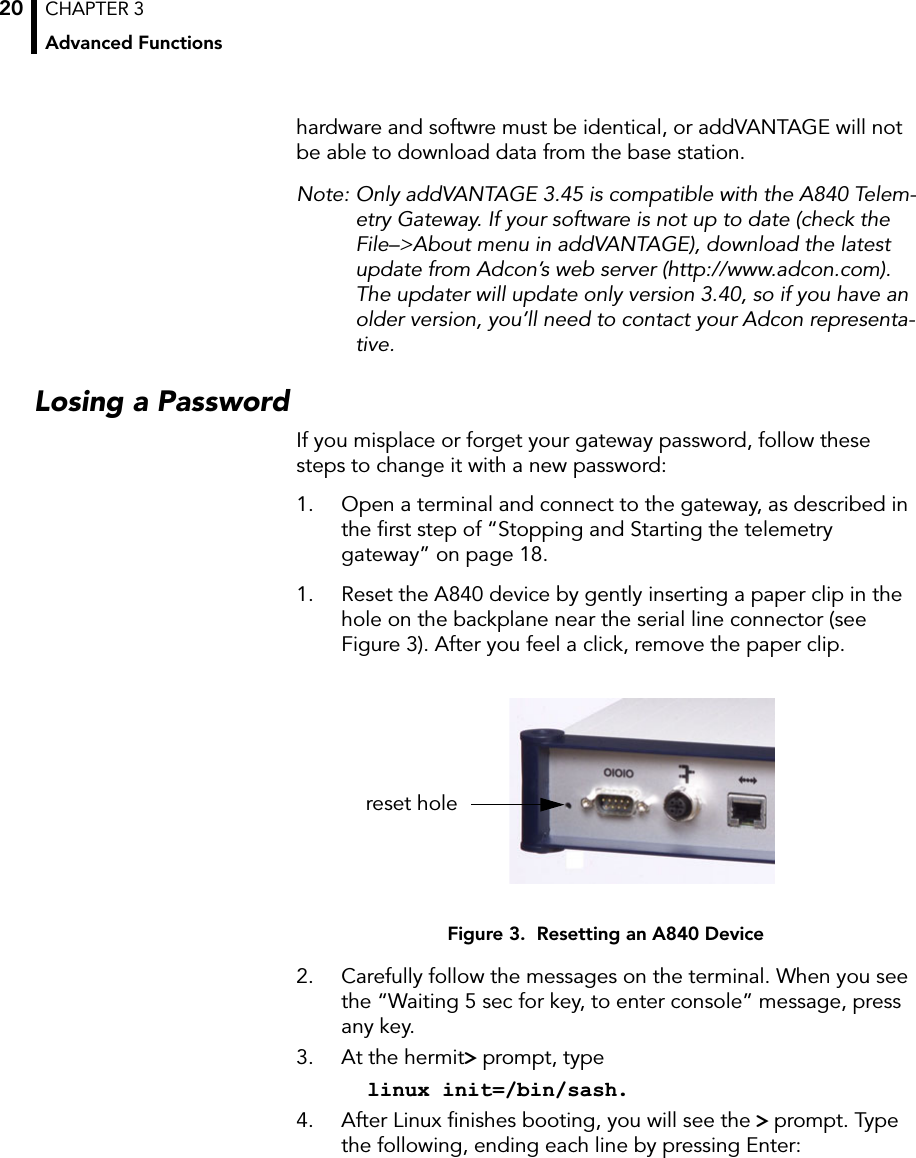
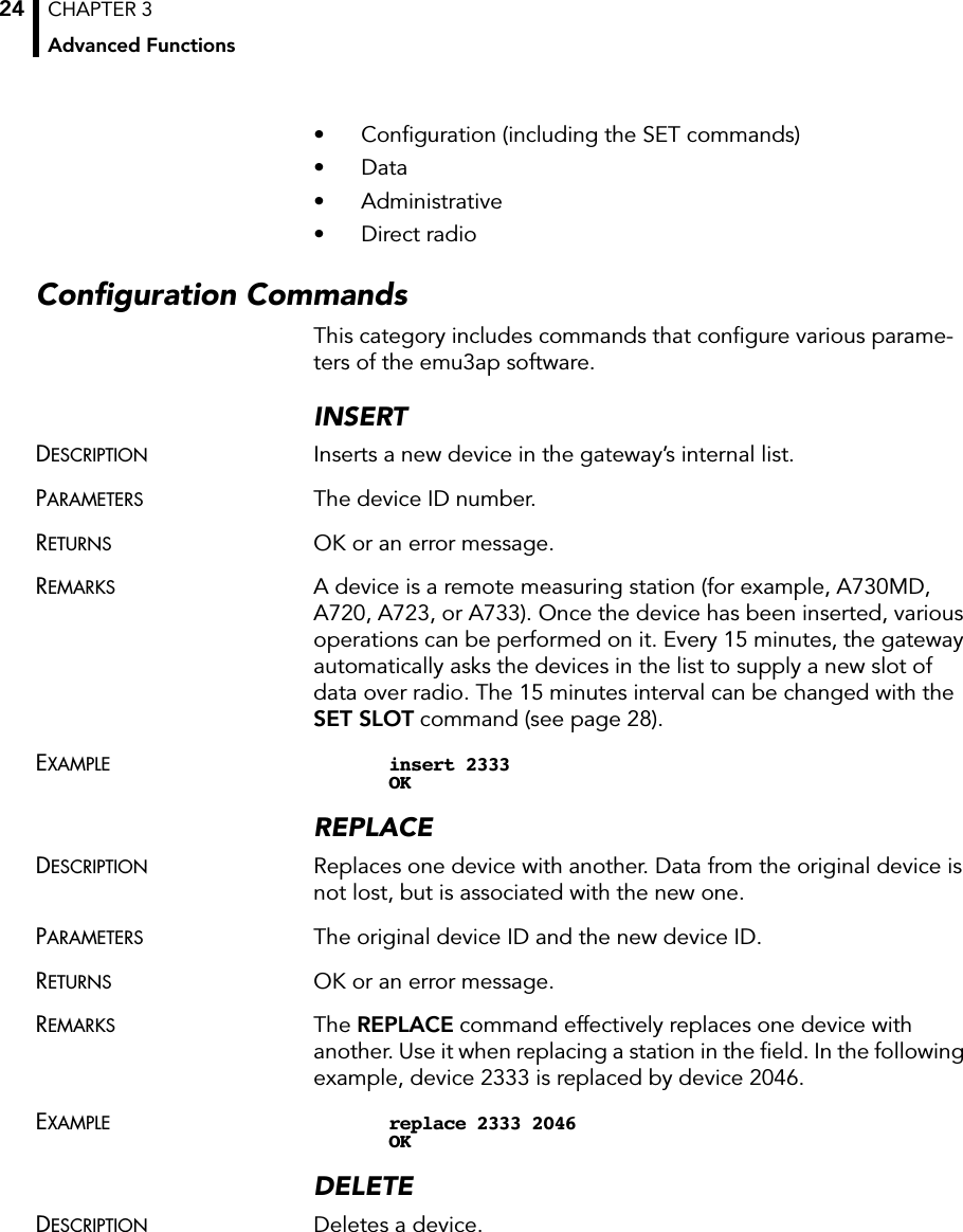
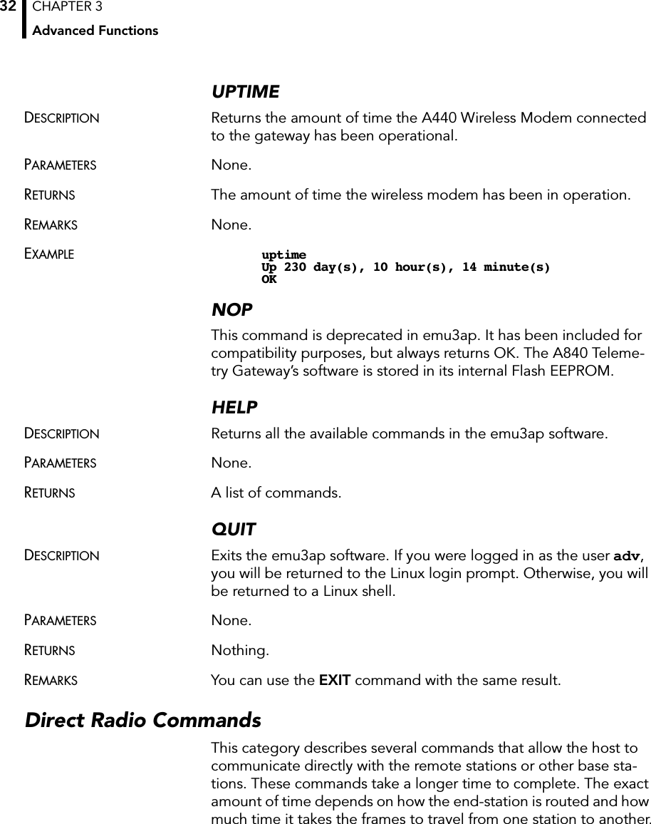
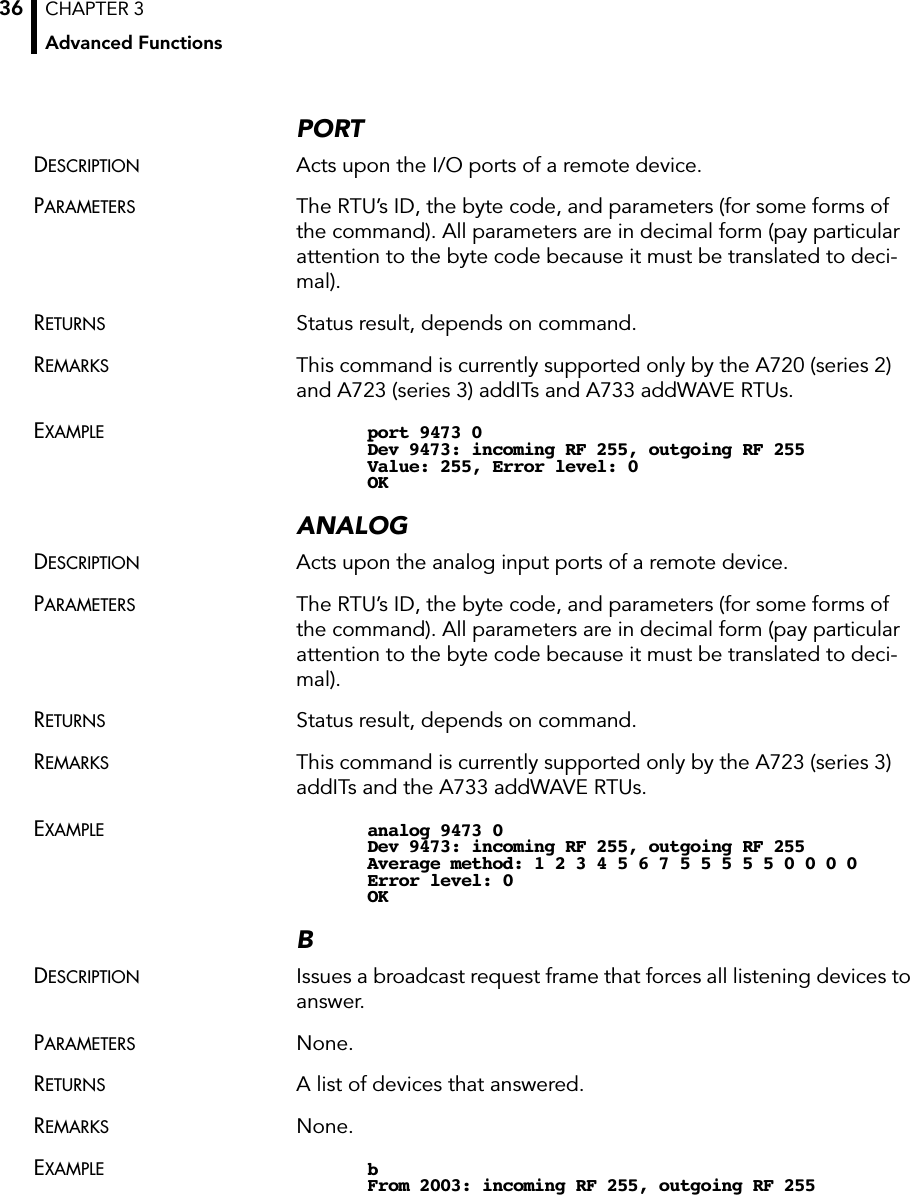
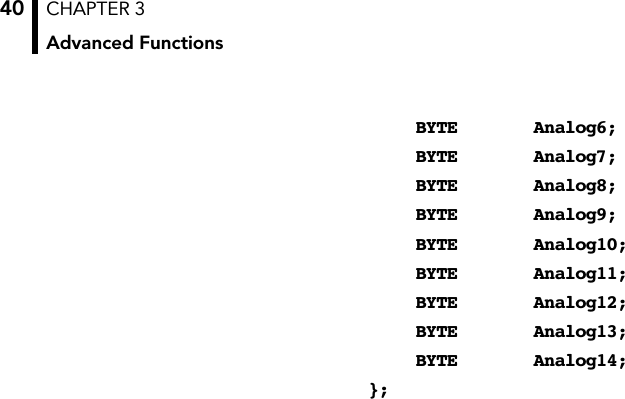
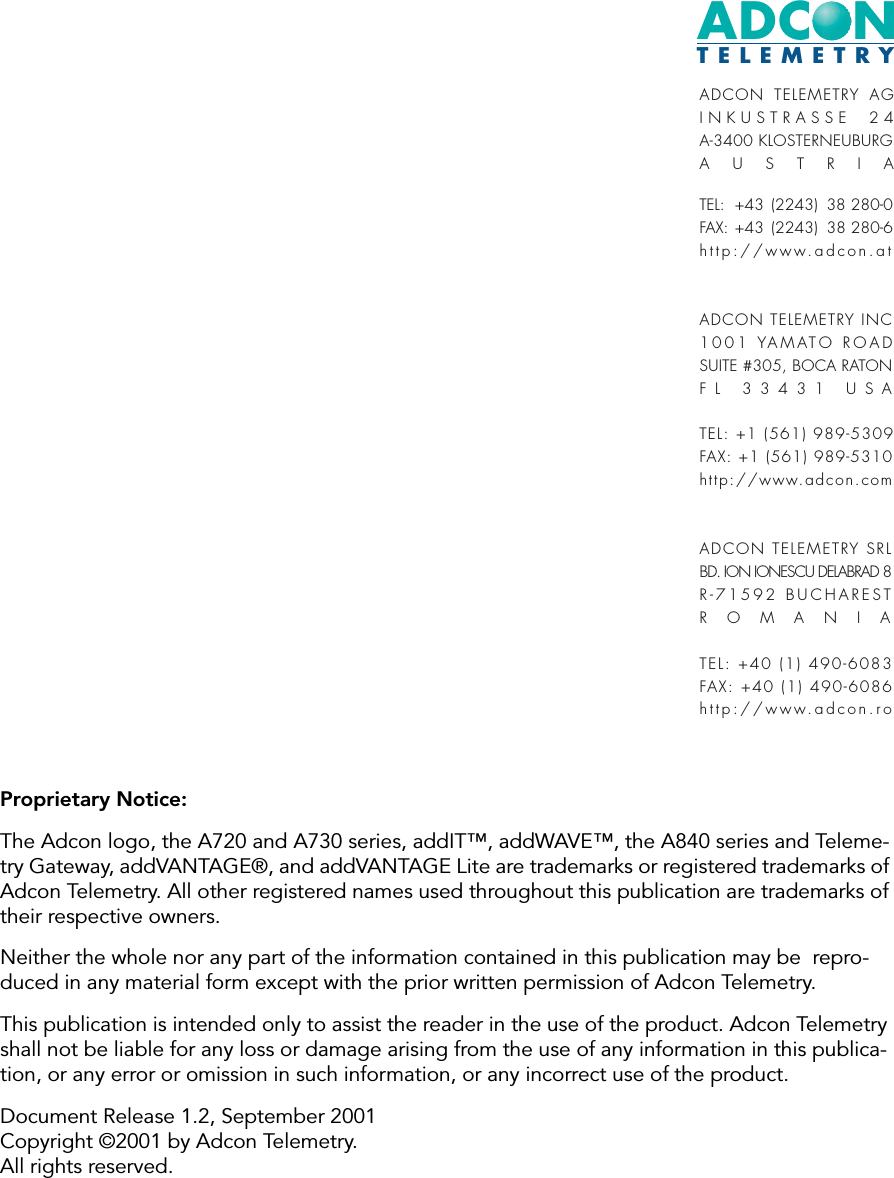
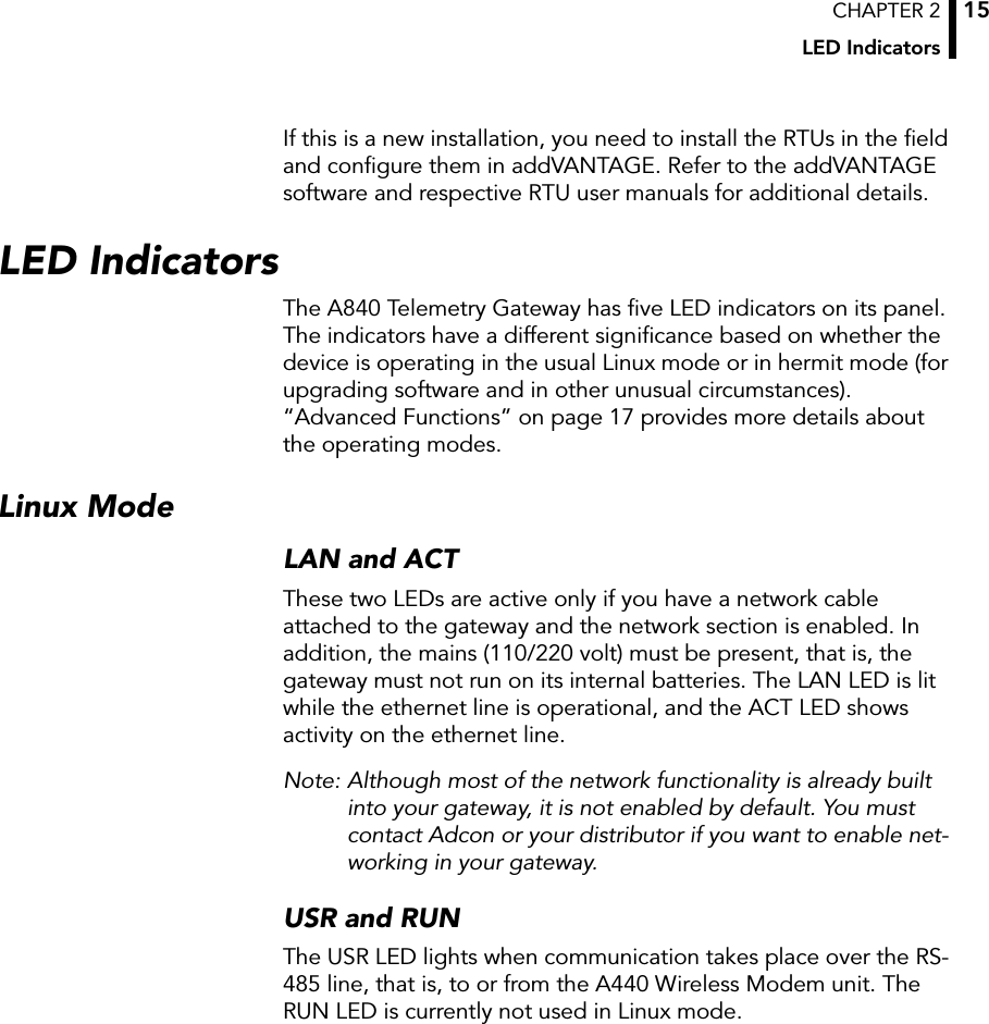
![CHAPTER 3Advanced Functions42The RF level is nonlinear and results from a table (which you can get from Adcon as an ASCII file). The value of the battery can be computed as follows:The digibyte is essentially the reflection of several inputs or internal status bits on the A730MD; its structure is described below:For more details, refer to the user manual for the A730MD device (addVANTAGE A730).The A720 (addIT) FramesThe addIT uses a reduced frame type (38). No adapter use for extending the inputs is possible.Type 38SIZE 14 (including the type byte).FORMAT struct tlg_type38 {BYTE RF_LevelIn;BYTE RF_LevelOut;BYTE DigiByte;BYTE PulseCounter0;BYTE PulseCounter1;BYTE BatteryLevel;BYTE Analog1;BYTE Analog2;BYTE Analog3;BYTE Analog4;BYTE Analog5;BYTE Analog6;BYTE Reserved;};Batt V[]BatteryLevel 20•255----------------------------------------------=B7 B6 B5 B4 B3 B2 B1 B0S.C. AUX:4 N.U. RAI:3 RAI:4 AUX:2 AUX:3 AUX:5S.C. = Solar Cell status N.U. = Not used RAI = Rain AUX = Aux](https://usermanual.wiki/Adcon-Telemetry/A840/User-Guide-221017-Page-42.png)
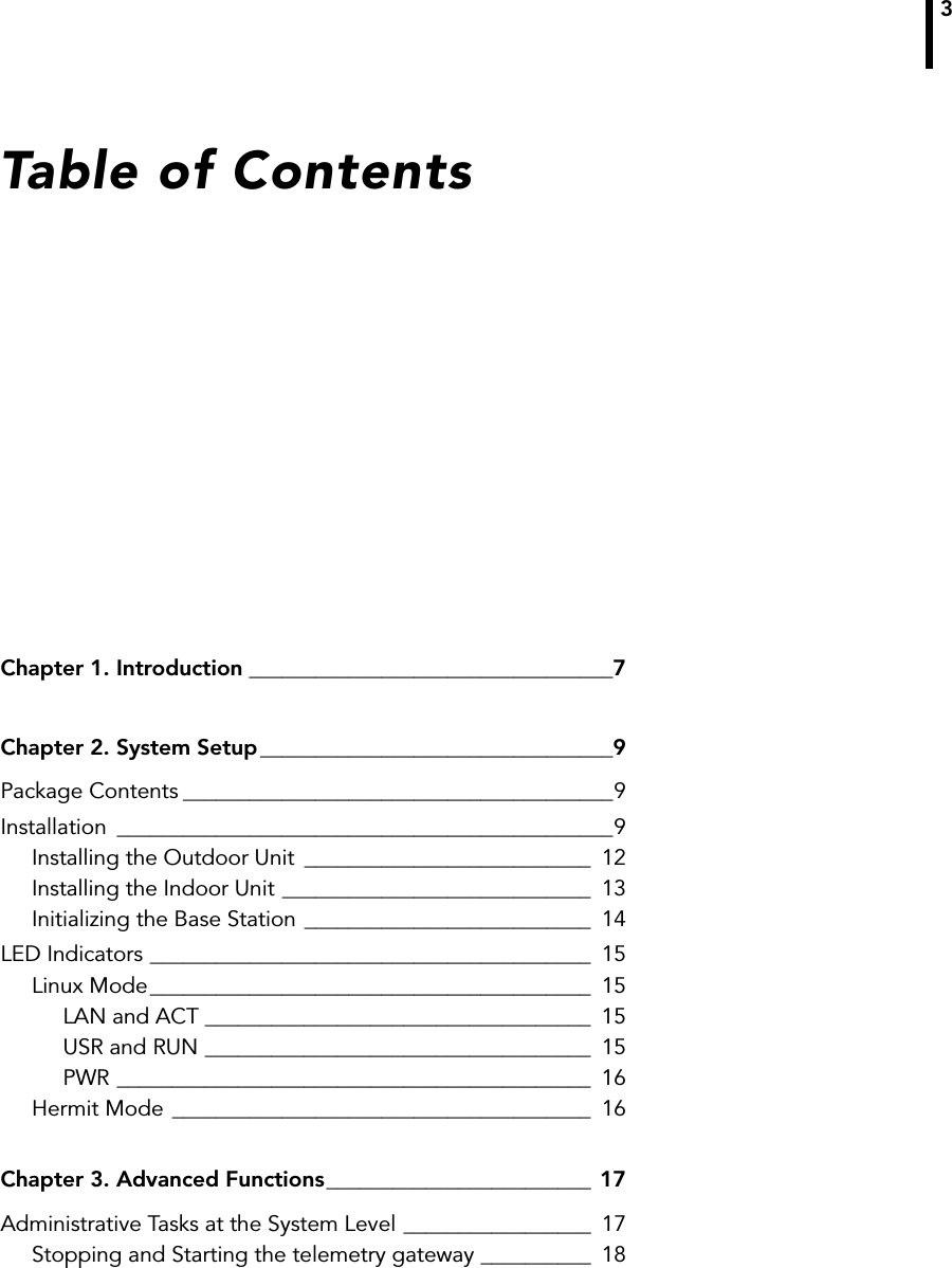
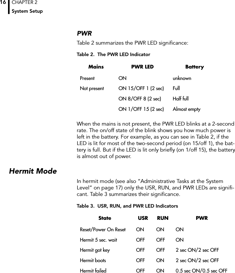
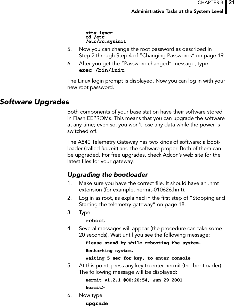
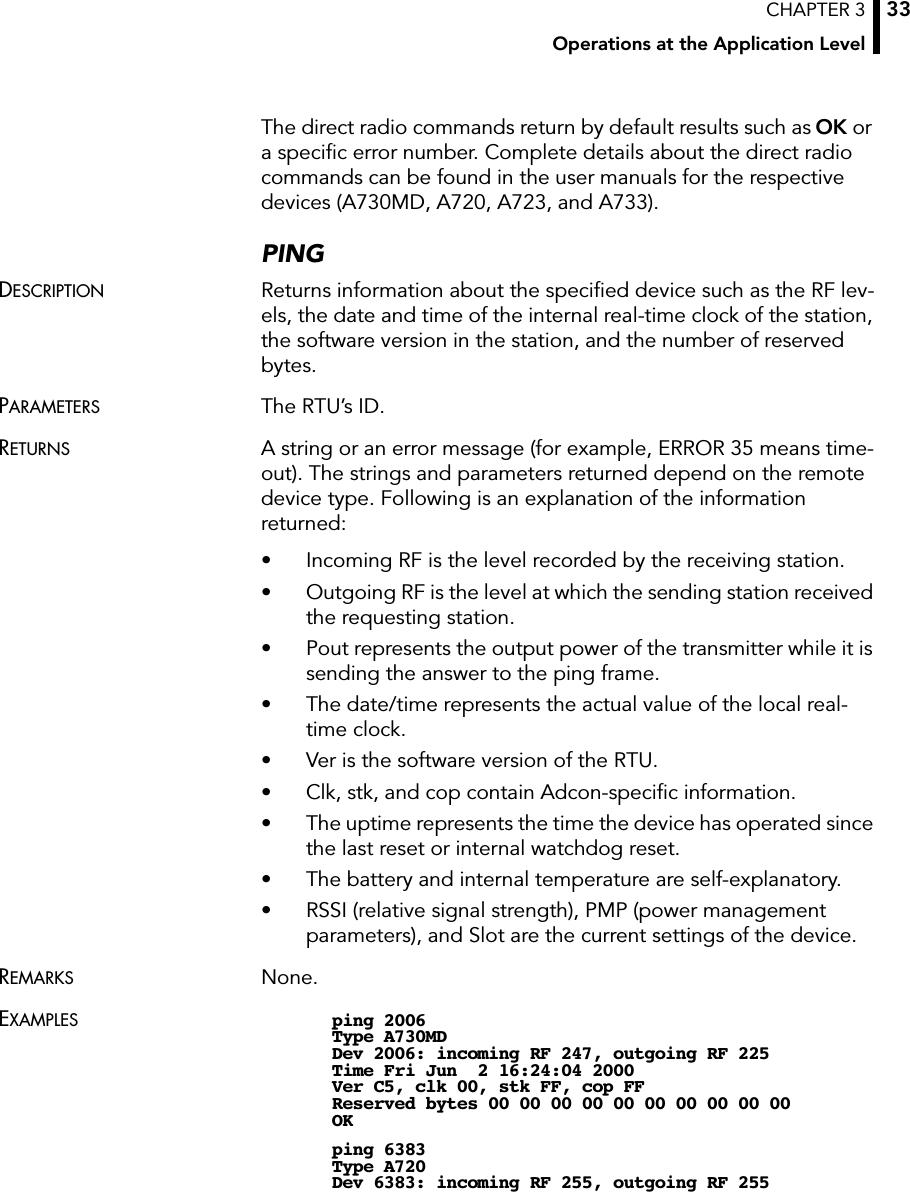
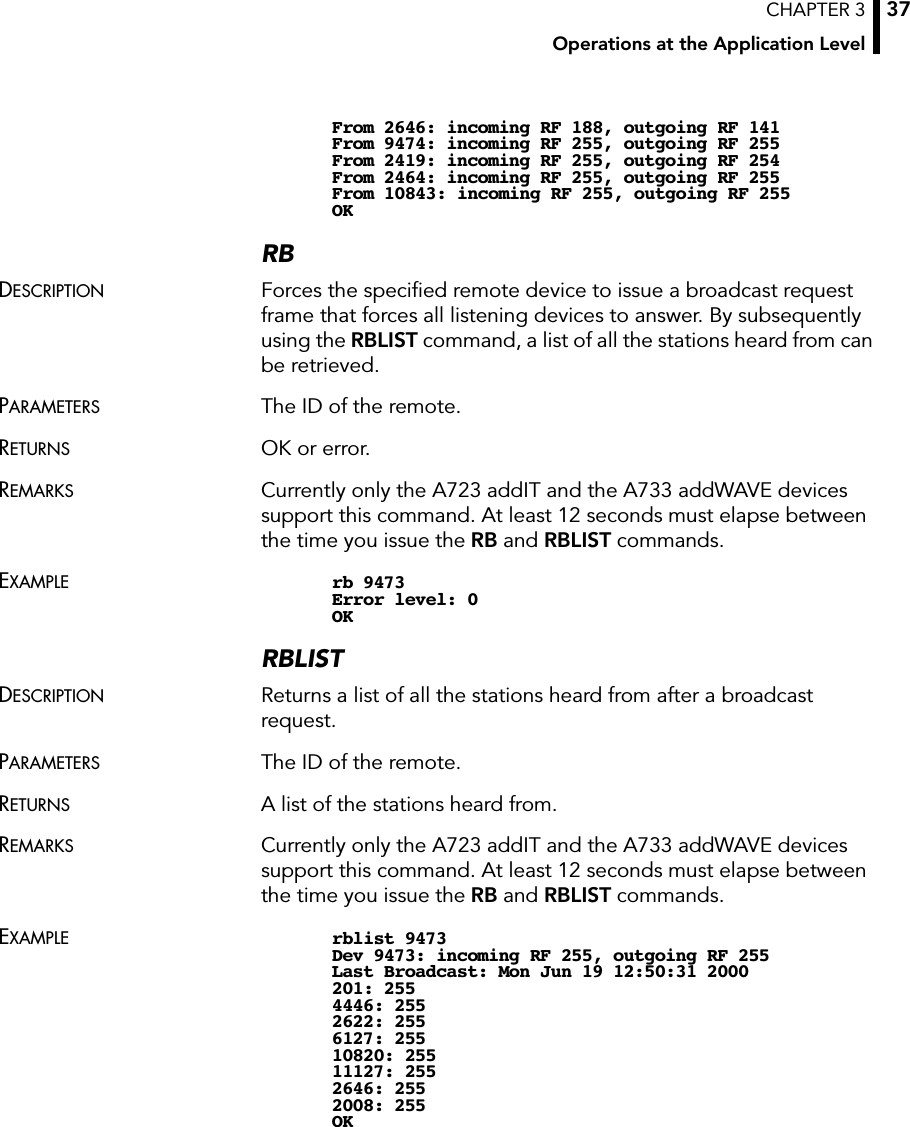
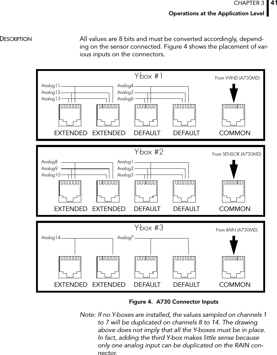
![CHAPTER 3Operations at the Application Level43DESCRIPTION All values are 8 bits and must be converted accordingly, depend-ing on the sensor connected. Figure 5 shows the placement of var-ious inputs on the connectors.Figure 5. A720 Connector InputsThe RF level is nonlinear and results from a table (which you can get from Adcon as an ASCII file). The value of the battery can be computed as follows:The digibyte is essentially the reflection of several inputs or inter-nal status bits on the A720; its structure is described below:For more details, refer to the user manual for the A720 device.The A723 (addIT series 3) FramesThe addIT series 3 implements currently two frame types, depend-ing on the compatibility mode flag: 38 (described on page 42) and 39. For more details about the compatibility flag, refer to the A720 series user manual.There is, however, a fundamental difference between frame 39 and the previously described data frames. The A723 samples the ana-log values with 10-bit resolution and stores them as 12-bit values. Analog1Analog2Analog3GroundPowerDIG0PulseCounter01234567Analog4Analog5Analog6GroundPowerDIG1PulseCounter11234567I/O A I/O BA720Batt V[]BatteryLevel 20•255----------------------------------------------=B7 B6 B5 B4 B3 B2 B1 B0S.C. res res res res res DIG1 DIG0S.C. = Solar Cell status res = reserved](https://usermanual.wiki/Adcon-Telemetry/A840/User-Guide-221017-Page-43.png)
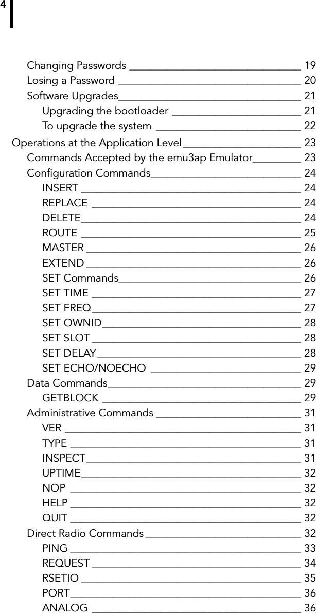
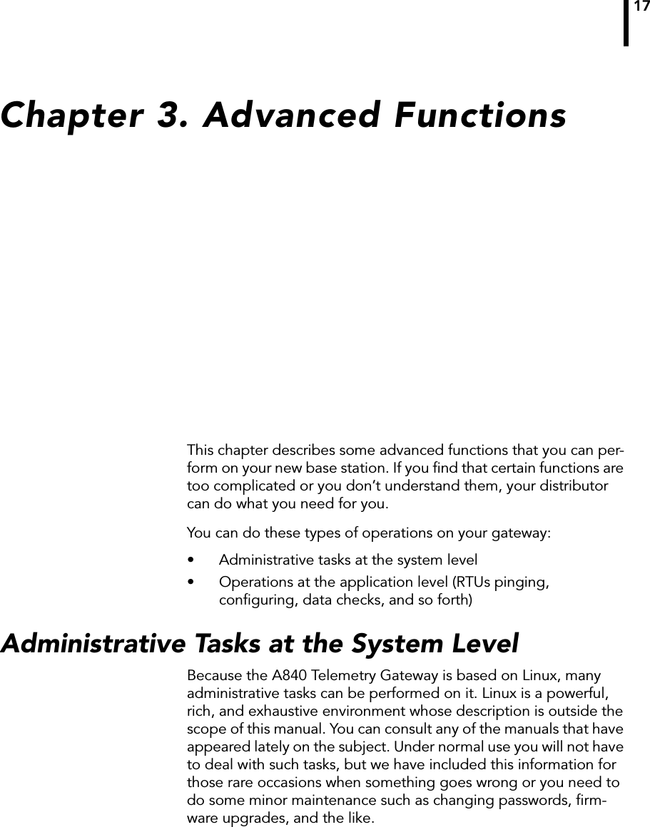
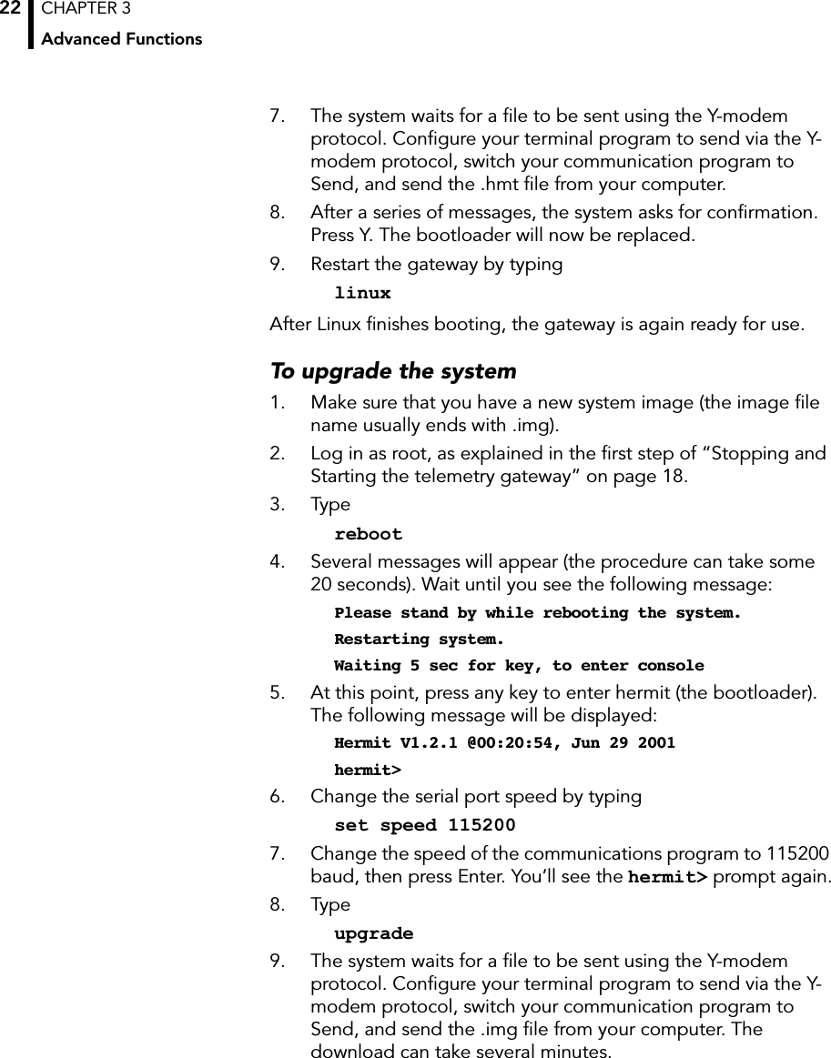
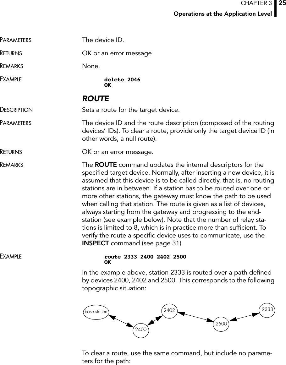
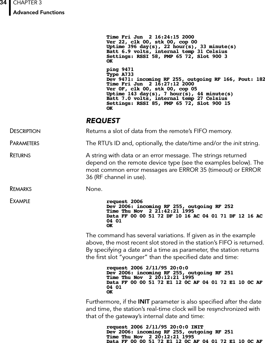
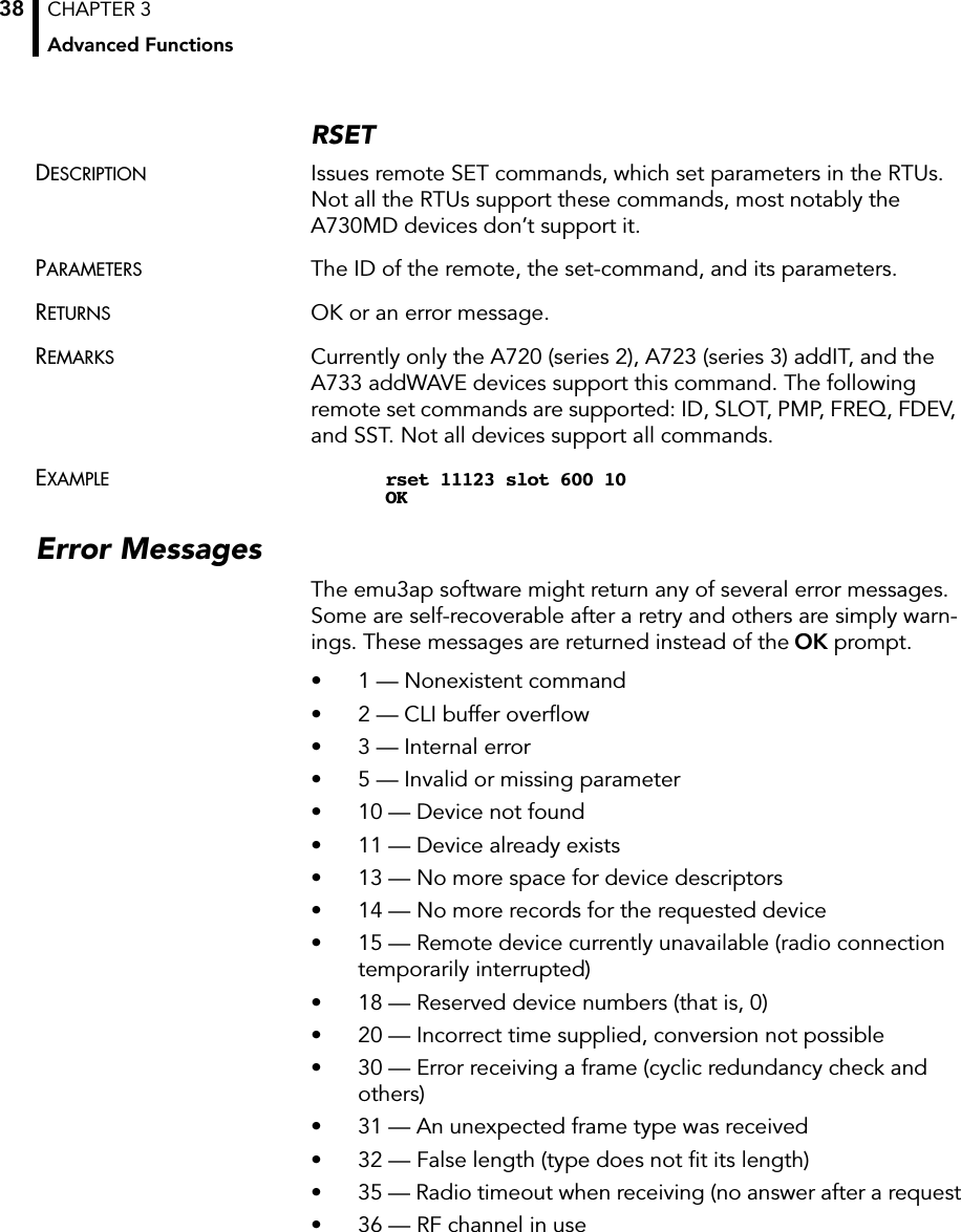
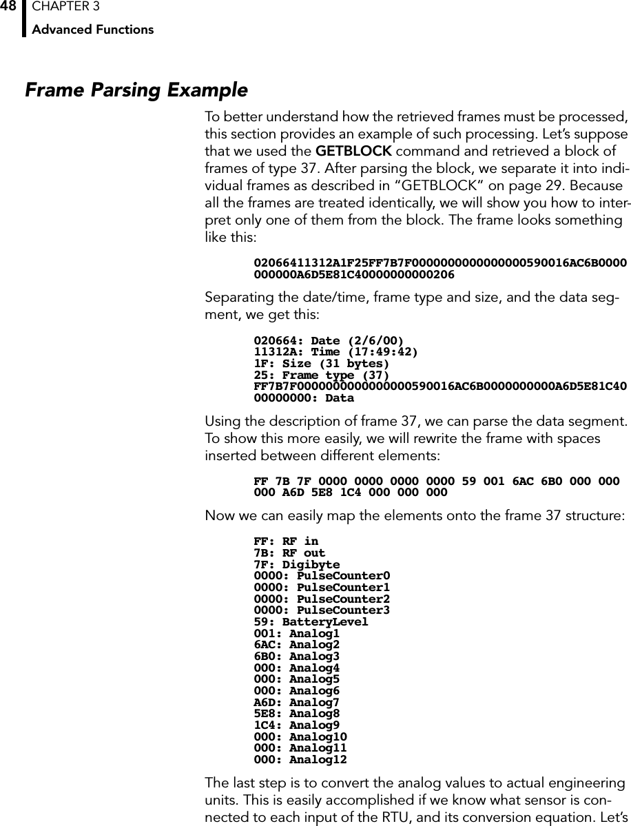
![CHAPTER 3Advanced Functions44Also, the A723 contains two 16-bit pulse counters, that is, it has more data to send. Due to the limited space available and to mini-mize the radio traffic, the frames are slightly compressed, in that six 12-bit values are packed in 9 bytes.Type 39SIZE 22 (including the type byte).FORMAT struct tlg_type37 {BYTE RF_LevelIn;BYTE RF_LevelOut;BYTE DigiByte;WORD PulseCounter0;WORD PulseCounter1;BYTE BatteryLevel;BYTE Analog[9];};DESCRIPTION The analog values are 12 bits and must be converted accordingly, depending on the sensor connected, while the pulse counters are 16-bit values. Only the RF and battery levels are 8-bit values. Analog[9] is an array of 9 unsigned bytes that is the result of packing the six 12-bit values. These are the values returned by the internal A/D converter from the respective I/O connectors.Note: The integers (16-bit values) are sent using the big endian convention, that is, first the most significant byte and then the least significant byte.The packing mechanism is shown in Figure 6.Figure 6. Type 39 Frame CompressionSix 16-bit values8-bit packed valuesAnalog1 Analog2 Analog3 Analog412 bits 12 bits 12 bits 12 bitsByte 0 Byte 1 Byte 2 Byte 3 Byte 6Byte 5Byte 4 Byte 7 Byte 8etc....0000](https://usermanual.wiki/Adcon-Telemetry/A840/User-Guide-221017-Page-44.png)
![CHAPTER 3Operations at the Application Level45Note: Only Analog1 to Analog6 are packed; the 16-bit Pulse Counters are not.Figure 7 shows the placement of various inputs on the connectors.Figure 7. A723 Connector InputsThe RF level is nonlinear and results from a table (which you can get from Adcon as an ASCII file). The value of the battery can be computed as follows:The digibyte is essentially the reflection of several inputs or inter-nal status bits on the A723; its structure is described below:For more details, refer to the user manual for the A723 device.The A733 (addWAVE) FramesThe addWAVE currently implements only one frame type (37). The A733 samples the analog values with 10-bit resolution and stores them as 12-bit values. Also, the A733 contains built-in logic to sample 12 different analog inputs, as well as four 16-bit pulse counters—all in all, substantially more data. Due to the limited space available and in order to minimize the radio traffic, the frames are slightly compressed, in that twelve 12-bit values are packed in nine 16-bit words.Analog4Analog5Analog6GroundPowerDIG1PulseCounter11234567Analog1Analog2Analog3GroundPowerDIG0PulseCounter01234567I/O A I/O BA723Batt V[]BatteryLevel 20•255----------------------------------------------=S.C. res res res DIG1 DIG0b0b7S.C. = Solar Cell status res = reservedres res](https://usermanual.wiki/Adcon-Telemetry/A840/User-Guide-221017-Page-45.png)
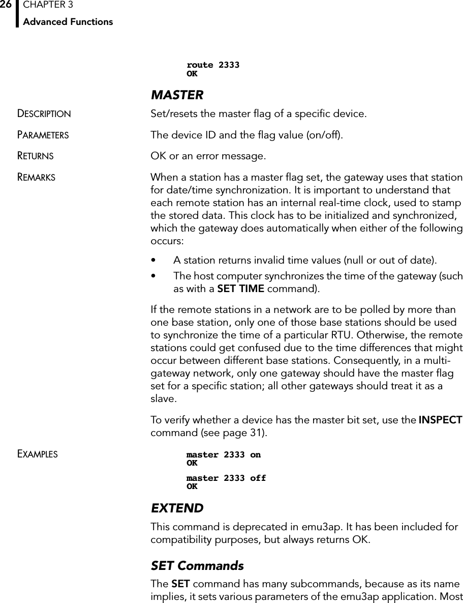
![CHAPTER 3Advanced Functions46Type 37SIZE 31 (including the type byte).FORMAT struct tlg_type37 {BYTE RF_LevelIn;BYTE RF_LevelOut;BYTE DigiByte;WORD PulseCounter0;WORD PulseCounter1;WORD PulseCounter2;WORD PulseCounter3;BYTE BatteryLevel;BYTE Analog[18];};DESCRIPTION The analog values are 12 bits and must be converted accordingly, depending on the sensor connected, while the pulse counters are 16-bit values. Only the RF and battery levels are 8-bit values. Analog[18] is an array of 18 unsigned bytes that is the result of packing the twelve 12-bit values. These are the values returned by the internal A/D converter from the respective I/O connectors.Note: The integers (16-bit values) are sent using the big endian convention, that is, first the most significant byte and then the least significant byte.The packing mechanism is shown in Figure 8.Figure 8. Type 37 Frame CompressionNote: Only Analog1 to Analog12 are packed; the 16-bit Pulse Counters are not.Twelve 16-bit values8-bit packed valuesAnalog1 Analog2 Analog3 Analog412 bits 12 bits 12 bits 12 bitsByte 0 Byte 1 Byte 2 Byte 3 Byte 6Byte 5Byte 4 Byte 16 Byte 17etc....0000](https://usermanual.wiki/Adcon-Telemetry/A840/User-Guide-221017-Page-46.png)
![CHAPTER 3Operations at the Application Level47Figure 9 show the placement of various inputs on the connectors.Figure 9. A733 Connector InputsThe RF level is nonlinear and results from a table (which you can get from Adcon as an ASCII file). The value of the battery can be computed as follows:The digibyte is essentially the reflection of several inputs or inter-nal status bits on the A733; its structure is described below:For more details, refer to the user manual for the A733 device.Analog4Analog5Analog6GroundPowerDIG1PulseCounter11234567Analog1Analog2Analog3GroundPowerDIG0PulseCounter01234567I/O A I/O BA733Analog7Analog8Analog9GroundPowerDIG2PulseCounter21234567I/O CAnalog10Analog11Analog12GroundPowerDIG3PulseCounter31234567I/O DBatt V[]BatteryLevel 20•255----------------------------------------------=S.C. res res res DIG3 DIG2 DIG1 DIG0b0b7S.C. = Solar Cell status res = reserved](https://usermanual.wiki/Adcon-Telemetry/A840/User-Guide-221017-Page-47.png)
![CHAPTER 3Operations at the Application Level49assume that a temperature sensor is connected to the Analog7 input. Then:Note that 2669 is A6D converted to decimal while the -40 was nec-essary because the standard Adcon temperature sensor has a range from -40 to 60 ºC.Similarly, the battery level can be computed as follows:Note here that we had to deal with an 8-bit value (59 hex = 89 dec-imal), so the divider is 255, while the previous example was based on a 12-bit conversion and the divider was 4095.Temp °C[]2669 100u4095------------------------- 4 0– 25.17==Batt V[]89 20u255---------------- 6 . 9 8==](https://usermanual.wiki/Adcon-Telemetry/A840/User-Guide-221017-Page-49.png)