Adcon Telemetry A840 Telemetry Gateway User Manual Base Station A840 440
Adcon Telemetry Inc Telemetry Gateway Base Station A840 440
Users manual

ADCON
TELEMETRY
Base Station
Telemetry Gateway A840 and
Wireless Modem A440
User Guide
SMART WIRELESS SOLUTIONS

ADCON
TELEMETRY
ADCON TELEMETRY AG
INKUSTRASSE 24
A-3400 KLOSTERNEUBURG
AUSTRIA
TEL: +43 (2243) 38 280-0
FAX: +43 (2243) 38 280-6
http://www.adcon.at
ADCON TELEMETRY INC
1001 YAMATO ROAD
SUITE #305, BOCA RATON
FL 33431 USA
TEL: +1 (561) 989-5309
FAX: +1 (561) 989-5310
http://www.adcon.com
ADCON TELEMETRY SRL
BD. ION IONESCU DELABRAD 8
R-71592 BUCHAREST
ROMANIA
TEL: +40 (1) 490-6083
FAX: +40 (1) 490-6086
http://www.adcon.ro
Proprietary Notice:
The Adcon logo, the A720 and A730 series, addIT™, addWAVE™, the A840 series and Teleme-
try Gateway, addVANTAGE®, and addVANTAGE Lite are trademarks or registered trademarks of
Adcon Telemetry. All other registered names used throughout this publication are trademarks of
their respective owners.
Neither the whole nor any part of the information contained in this publication may be repro-
duced in any material form except with the prior written permission of Adcon Telemetry.
This publication is intended only to assist the reader in the use of the product. Adcon Telemetry
shall not be liable for any loss or damage arising from the use of any information in this publica-
tion, or any error or omission in such information, or any incorrect use of the product.
Document Release 1.2, September 2001
Copyright ©2001 by Adcon Telemetry.
All rights reserved.

3
Table of Contents
Chapter 1. Introduction _________________________________7
Chapter 2. System Setup ________________________________9
Package Contents _______________________________________9
Installation _____________________________________________9
Installing the Outdoor Unit __________________________ 12
Installing the Indoor Unit ____________________________ 13
Initializing the Base Station __________________________ 14
LED Indicators ________________________________________ 15
Linux Mode________________________________________ 15
LAN and ACT ___________________________________ 15
USR and RUN ___________________________________ 15
PWR ___________________________________________ 16
Hermit Mode ______________________________________ 16
Chapter 3. Advanced Functions________________________ 17
Administrative Tasks at the System Level _________________ 17
Stopping and Starting the telemetry gateway __________ 18

4
Changing Passwords ________________________________ 19
Losing a Password __________________________________ 20
Software Upgrades__________________________________ 21
Upgrading the bootloader ________________________ 21
To upgrade the system ___________________________ 22
Operations at the Application Level______________________ 23
Commands Accepted by the emu3ap Emulator_________ 23
Configuration Commands____________________________ 24
INSERT _________________________________________ 24
REPLACE _______________________________________ 24
DELETE_________________________________________ 24
ROUTE _________________________________________ 25
MASTER ________________________________________ 26
EXTEND ________________________________________ 26
SET Commands__________________________________ 26
SET TIME _______________________________________ 27
SET FREQ_______________________________________ 27
SET OWNID_____________________________________ 28
SET SLOT _______________________________________ 28
SET DELAY______________________________________ 28
SET ECHO/NOECHO ____________________________ 29
Data Commands____________________________________ 29
GETBLOCK _____________________________________ 29
Administrative Commands ___________________________ 31
VER ____________________________________________ 31
TYPE ___________________________________________ 31
INSPECT________________________________________ 31
UPTIME_________________________________________ 32
NOP ___________________________________________ 32
HELP ___________________________________________ 32
QUIT ___________________________________________ 32
Direct Radio Commands _____________________________ 32
PING ___________________________________________ 33
REQUEST _______________________________________ 34
RSETIO _________________________________________ 35
PORT___________________________________________ 36
ANALOG _______________________________________ 36

5
B ______________________________________________ 36
RB _____________________________________________ 37
RBLIST _________________________________________ 37
RSET ___________________________________________ 38
Error Messages_____________________________________ 38
Frame Types _______________________________________ 39
The A730MD frames _____________________________ 39
Type 9__________________________________________ 39
The A720 (addIT) Frames _________________________ 42
Type 38 ________________________________________ 42
The A723 (addIT series 3) Frames__________________ 43
Type 39 ________________________________________ 44
The A733 (addWAVE) Frames _____________________ 45
Type 37 ________________________________________ 46
Frame Parsing Example _____________________________ 48

6

7
Chapter 1. Introduction
This manual describes the use of the A840 Telemetry Gateway and
A440 Wireless Modem combination. Due to their general nature,
either unit can also be used independently, but such uses are
beyond the scope of this manual. The manual teaches you how to
use the telemetry gateway and the wireless modem as a base sta-
tion for an Adcon wireless network.
To build a network, you need one or more A730MD, A733, A720,
or A723 remote telemetry units (RTUs), an A840/A440 base sta-
tion, and the addVANTAGE software. For additional information
concerning the RTUs and the addVANTAGE software, consult the
respective user manuals.
The A840 Telemetry Gateway is a low-power, battery-backed
device that acts as an interface between an Adcon wireless net-
work and one or more hosts running addVANTAGE or similar data
acquisition software. The gateway is based on a powerful 32-bit
processor running the Linux operating system. It has 16-MB Flash
EPROM acting as a hard disk and 16 MB RAM. The software can
be upgraded in the field.
Several interfaces are available: ethernet, V34 modem, RS-232
serial, and RS-485 multidrop serial. A built-in rechargeable battery

CHAPTER 1
Introduction
8
provides the telemetry gateway with at least 24 hours of operation
without mains power.
The A440 Wireless Modem is a low-power, narrow-band data trans-
ceiver operating in the 70-cm band. It implements Adcon’s low-
speed radio protocol and is therefore compatible with all Adcon
RTUs. In addition the A440 modem supports a high-speed wireless
protocol that will be used by future Adcon devices.
The A440 has an 8-bit Flash-based microcontroller that can also be
upgraded in the field.
NOTE FOR USA: THIS DEVICE COMPLIES WITH PART 15 OF THE
FCC RULES. OPERATION IS SUBJECT TO THE CONDITION THAT
THIS DEVICE DOES NOT CAUSE HARMFUL INTERFERENCE.

9
Chapter 2. System Setup
Package Contents
Before proceeding to the installation of your base station, first ver-
ify that you received all of the following components:
• The A840 Telemetry Gateway
• The A440 Wireless Modem
• The 30 m (100 ft) connection cable between the A840 and the
A440 devices
• A power cord
• A twisted-pair ethernet cable (not used at this time, but
included in the package)
• A serial null modem cable
• A whip antenna
If any of the above items is missing, contact your dealer.
Installation
The base station has two main components: an indoor unit (the
A840) and an outdoor unit (the A440).

CHAPTER 2
System Setup
10
Before proceeding with the installation, take a moment to plan
your network. First, it is essential to realize the importance of
selecting a good location for the base station. You must consider
several factors, some of them quite contradictory, when you select
this location:
• From a radio perspective, the height of the receiving antenna
is essential: the higher the antenna, the greater the range of
communication.
• The base station should be situated in the same building
where the personnel managing the base station work, or at
least spend some of their time.
• Places like cellars, near heat sources, or damp locations are
not suitable.
• Geographically, it is better to have the base station in the
center of the area where the RTUs will be installed.
• If you plan to use the base station as a server to allow other
people to log in and get data, you have to make certain that a
telephone line is available exclusively for this use.
• A telephone connection next to the PC is also very important
for when you need technical support.
The communication distance you can achieve is directly propor-
tional to the height of the receiving antenna. The propagation
mode of the waves the Adcon system uses is basically the line of
sight. Due to the curvature of the earth, on flat terrain, the maxi-
mum distance reached depends on the height of the receiver and
of the measuring stations’ antennas. You can’t do much on the
remote station side, but you have more options with the base sta-

CHAPTER 2
Installation
11
tion. Some typical examples of the achieved distances, under vari-
ous conditions, are shown in Table 1.
The addIT RTU, however, uses low-power technology and was not
designed to communicate over large distances. The typical “line-
of sight” distance an addIT can communicate is 800 m (approxi-
mately half a mile). This is valid if the partner device is mounted on
a 3 m mast (9 ft) and the addIT is mounted on a 30 cm mast (1 ft).
The above figures are estimates based on a great deal of experi-
ence with installing this kind of equipment and assume a typical
height of 3 m (9 ft) for the antennas of the remote measuring sta-
tions. Similarly, ideal physical conditions are assumed for the ter-
rain including a flat, open, nonurban environment.
What conclusions can be drawn from Table 1? Primarily, you can
see the importance of having the base station antenna as high as
possible. To gain antenna height, you have several options:
• Build a mast directly on the ground; however, a 30 m (100 ft)
mast may not be a practical option.
• Set up a mast on a tall building (of course, it has to be the
building where you want to have the base station).
• Install the base station in a building that is situated on a hill.
Note that the cable for the outdoor unit delivered with the system
is 30 m long (about 100 ft). This means you must locate your
indoor unit no more than 30 m from the outdoor unit. Lengthening
the cable is not recommended, because the signal strength loss is
significant.
Table 1. Communication Between Base Station and
A730MD/A733
Receiving antenna
height
Typical distances
achieved
6 m (18 ft) 5 km (3 miles)
10 m (31 ft) 8 km (5 miles)
20 m (62 ft) 16 km (10 miles)
30 m (92 ft) 24 km (15 miles)

CHAPTER 2
System Setup
12
To use the telemetry gateway and wireless modem, you need to do
the following:
• Install the outdoor unit.
• Install the indoor unit.
• Initialize the base station.
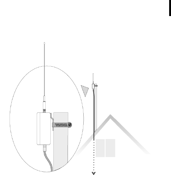
Installing the Outdoor Unit
Install the outdoor unit on the rooftop of the house where the base
station will be located or on top of a nearby mast.
After unpacking the components of the base station, identify the
device marked “Wireless Modem A440.” This unit has two connec-
tors: one for a whip antenna (also supplied in the package) and a
second that accommodates the 30 m (100 ft) connection cable to
the indoor unit.
Note: This operation should be performed by a certified electri-
cian. Make sure that the mast on which the A440 Wireless
Modem will be installed is properly grounded.
Complete the following steps to install the outdoor unit:
1. Fasten the wireless modem to the aluminum mast (provided
by Adcon) using the supplied ring clamp.
2. Fasten the antenna to the wireless modem.
3. Plug the proper end of the communication cable into the
lower connector of the wireless modem.
4. Secure the mast in its place on the roof.
5. Run the cable to the indoor unit.
Figure 1 illustrates these steps.
CHAPTER 2
Installation
13
Figure 1. Outdoor Unit Installation
Note: The cable supplied to connect the outdoor unit to the A840
Telemetry Gateway is 30 m long and cannot be extended.
Extending the cable will make your wireless modem inoper-
able due to the voltage loss on the additional cable length.
You can, however, install an outdoor antenna and use a
coaxial cable (max. 30 m) between the A440 unit and the
antenna, giving you a total of 60 m distance between the
indoor unit and the outdoor antenna.
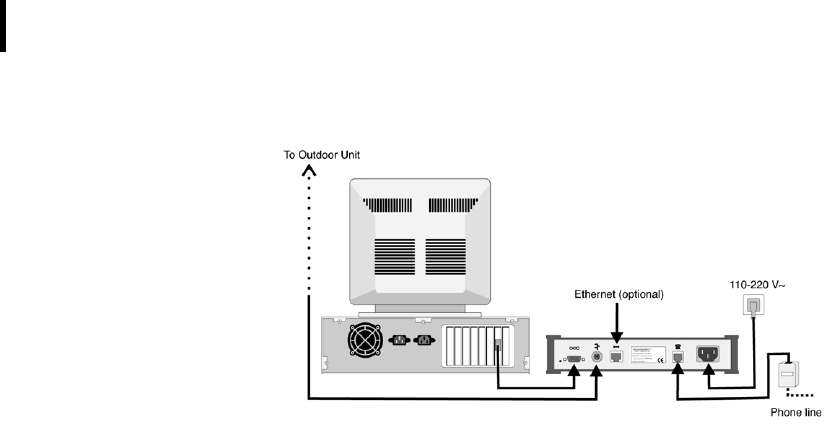
Installing the Indoor Unit
First identify the device marked “Telemetry Gateway A840,” which
is the indoor unit. Then connect the cables to the gateway as
shown in Figure 2.
CHAPTER 2
System Setup
14
Figure 2. Indoor Unit Installation
If you plan to use the base station as a standalone unit (that is,
without a computer), you need a telephone line that must be con-
nected to the modem jack of the A840 gateway.
Note: Before you operate the base station, Adcon recommends
that you let the internal battery charge to a level where it can
sustain the operation of the gateway. You can do this by
plugging the power cable into the A840 device, but leaving
the serial cable to the A440 outdoor unit disconnected for at
least six hours.
Initializing the Base Station
For the base station to operate properly, you must start the
addVANTAGE software. Make sure that the software is properly
configured (the serial port, and so forth); for additional configura-
tion details, refer to the respective software manual. If your base
station operates standalone (as dumb server), initiate a call through
addVANTAGE to configure the gateway.
If you are installing the base station as replacement for an A730SD
receiver, just upgrade your addVANTAGE installation to version
3.45 or higher (earlier versions don’t support the A840 Telemetry
Gateway). After starting addVANTAGE, your new base station will
be configured automatically.

CHAPTER 2
LED Indicators
15
If this is a new installation, you need to install the RTUs in the field
and configure them in addVANTAGE. Refer to the addVANTAGE
software and respective RTU user manuals for additional details.
LED Indicators
The A840 Telemetry Gateway has five LED indicators on its panel.
The indicators have a different significance based on whether the
device is operating in the usual Linux mode or in hermit mode (for
upgrading software and in other unusual circumstances).
“Advanced Functions” on page 17 provides more details about
the operating modes.
Linux Mode
LAN and ACT
These two LEDs are active only if you have a network cable
attached to the gateway and the network section is enabled. In
addition, the mains (110/220 volt) must be present, that is, the
gateway must not run on its internal batteries. The LAN LED is lit
while the ethernet line is operational, and the ACT LED shows
activity on the ethernet line.
Note: Although most of the network functionality is already built
into your gateway, it is not enabled by default. You must
contact Adcon or your distributor if you want to enable net-
working in your gateway.
USR and RUN
The USR LED lights when communication takes place over the RS-
485 line, that is, to or from the A440 Wireless Modem unit. The
RUN LED is currently not used in Linux mode.

CHAPTER 2
System Setup
16
PWR
Table 2 summarizes the PWR LED significance:
When the mains is not present, the PWR LED blinks at a 2-second
rate. The on/off state of the blink shows you how much power is
left in the battery. For example, as you can see in Table 2, if the
LED is lit for most of the two-second period (on 15/off 1), the bat-
tery is full. But if the LED is lit only briefly (on 1/off 15), the battery
is almost out of power.
Hermit Mode
In hermit mode (see also “Administrative Tasks at the System
Level” on page 17) only the USR, RUN, and PWR LEDs are signifi-
cant. Table 3 summarizes their significance.
Table 2. The PWR LED Indicator
Mains PWR LED Battery
Present ON unknown
Not present ON 15/OFF 1 (2 sec) Full
ON 8/OFF 8 (2 sec) Half full
ON 1/OFF 15 (2 sec) Almost empty
Table 3. USR, RUN, and PWR LED Indicators
State USR RUN PWR
Reset/Power On Reset ON ON ON
Hermit 5 sec. wait OFF OFF ON
Hermit got key OFF OFF 2 sec ON/2 sec OFF
Hermit boots OFF ON 2 sec ON/2 sec OFF
Hermit failed OFF ON 0.5 sec ON/0.5 sec OFF

17
Chapter 3. Advanced Functions
This chapter describes some advanced functions that you can per-
form on your new base station. If you find that certain functions are
too complicated or you don’t understand them, your distributor
can do what you need for you.
You can do these types of operations on your gateway:
• Administrative tasks at the system level
• Operations at the application level (RTUs pinging,
configuring, data checks, and so forth)
Administrative Tasks at the System Level
Because the A840 Telemetry Gateway is based on Linux, many
administrative tasks can be performed on it. Linux is a powerful,
rich, and exhaustive environment whose description is outside the
scope of this manual. You can consult any of the manuals that have
appeared lately on the subject. Under normal use you will not have
to deal with such tasks, but we have included this information for
those rare occasions when something goes wrong or you need to
do some minor maintenance such as changing passwords, firm-
ware upgrades, and the like.

CHAPTER 3
Advanced Functions
18
Stopping and Starting the telemetry gateway
The telemetry gateway has a built-in rechargeable battery that is
software controlled. If for some reason you need to stop the telem-
etry gateway (for example, shipping for service or storing for
longer time spans), you need to shut it down by switching off the
battery internally, then unplugging the power cable. Proceed as
follows:
1. Shut down addVANTAGE and log into the gateway by means
of a communication terminal (for example, Hyperterminal in
Windows, Zterm or BlackNight on a Mac, or minicom in Linux).
Use the standard parameters:
• 19200 baud
• 1 stop bit
• No parity
• Hardware protocol
• Send CR after LF.
A login prompt such as the following appears:
telemetry gateway A840 (Drau, Linux 2.4.0-rmk2-
bluemug1-ges5)
(C) 2001 Adcon Telemetry AG
A840 login:
2. At the A840 login prompt, type root.
3. At the password prompt, type 840sw.
Note: The default root password is programmed at the factory. For
security reasons, it is strongly recommended to change it.
For more details on how to change it, see “Changing Pass-
words” on page 19.
4. The > prompt appears. Type halt.
5. Several messages appear on your terminal. After you see the
last message shown below, you can unplug the unit from the
power outlet, because the internal battery is now off.
The system is going down NOW !!
Sending SIGTERM to all processes.
Terminated.
Sending SIGKILL to all processes.
The system is halted. Press Reset or turn off power.
System halted.

CHAPTER 3
Administrative Tasks at the System Level
19
To start the unit, plug the mains cable into the power outlet. After
the boot procedure finishes (which takes about 20 seconds), the
unit is fully operational.
Changing Passwords
For security reasons you might want to change the password of
your gateway. The unit comes from the factory with only two users:
root and adv. The root user is intended only for administrative
tasks, while adv is used by the addVANTAGE software. The pass-
word for root is 840sw and for adv it is addvantage. You can
change either password, but if you do so, be sure to keep the new
passwords in a secure location.
Complete the following steps to change the root password:
1. Log into the gateway as root, as described in the first step of
“Stopping and Starting the telemetry gateway” on page 18.
2. At the login prompt, type passwd.
3. The system prompts you to enter a new password:
Changing password for root.
Enter the new password (minimum of 5, maximum of 8
characters).
Please use a combination of upper and lower case let-
ters and numbers.
Enter new password:
4. After you enter the new password, the system prompts you to
reenter it to be sure that you didn’t mistype it. Reenter the
password:
Re-enter new password:
Password changed.
To change the password for the user adv, the steps are the same,
except that you start with:
passwd adv
If you do change the password for the user adv, you must also
change it in addVANTAGE. To do this, edit the agroexp.ini file.
Find the section [Communication], which has the following entries:
User=adv
Password=addvantage
Do not change the user name, but type whatever new password
you assigned to the adv user. The two password strings in the

CHAPTER 3
Advanced Functions
20
hardware and softwre must be identical, or addVANTAGE will not
be able to download data from the base station.
Note: Only addVANTAGE 3.45 is compatible with the A840 Telem-
etry Gateway. If your software is not up to date (check the
File–>About menu in addVANTAGE), download the latest
update from Adcon’s web server (http://www.adcon.com).
The updater will update only version 3.40, so if you have an
older version, you’ll need to contact your Adcon representa-
tive.
Losing a Password
If you misplace or forget your gateway password, follow these
steps to change it with a new password:
1. Open a terminal and connect to the gateway, as described in
the first step of “Stopping and Starting the telemetry
gateway” on page 18.
1. Reset the A840 device by gently inserting a paper clip in the
hole on the backplane near the serial line connector (see
Figure 3). After you feel a click, remove the paper clip.
Figure 3. Resetting an A840 Device
2. Carefully follow the messages on the terminal. When you see
the “Waiting 5 sec for key, to enter console” message, press
any key.
3. At the hermit> prompt, type
linux init=/bin/sash.
4. After Linux finishes booting, you will see the > prompt. Type
the following, ending each line by pressing Enter:
reset hole

CHAPTER 3
Administrative Tasks at the System Level
21
stty igncr
cd /etc
/etc/rc.sysinit
5. Now you can change the root password as described in
Step 2 through Step 4 of “Changing Passwords” on page 19.
6. After you get the “Password changed” message, type
exec /bin/init.
The Linux login prompt is displayed. Now you can log in with your
new root password.
Software Upgrades
Both components of your base station have their software stored
in Flash EEPROMs. This means that you can upgrade the software
at any time; even so, you won’t lose any data while the power is
switched off.
The A840 Telemetry Gateway has two kinds of software: a boot-
loader (called hermit) and the software proper. Both of them can
be upgraded. For free upgrades, check Adcon’s web site for the
latest files for your gateway.
Upgrading the bootloader
1. Make sure you have the correct file. It should have an .hmt
extension (for example, hermit-010626.hmt).
2. Log in as root, as explained in the first step of “Stopping and
Starting the telemetry gateway” on page 18.
3. Type
reboot
4. Several messages will appear (the procedure can take some
20 seconds). Wait until you see the following message:
Please stand by while rebooting the system.
Restarting system.
Waiting 5 sec for key, to enter console
5. At this point, press any key to enter hermit (the bootloader).
The following message will be displayed:
Hermit V1.2.1 @00:20:54, Jun 29 2001
hermit>
6. Now type
upgrade

CHAPTER 3
Advanced Functions
22
7. The system waits for a file to be sent using the Y-modem
protocol. Configure your terminal program to send via the Y-
modem protocol, switch your communication program to
Send, and send the .hmt file from your computer.
8. After a series of messages, the system asks for confirmation.
Press Y. The bootloader will now be replaced.
9. Restart the gateway by typing
linux
After Linux finishes booting, the gateway is again ready for use.
To upgrade the system
1. Make sure that you have a new system image (the image file
name usually ends with .img).
2. Log in as root, as explained in the first step of “Stopping and
Starting the telemetry gateway” on page 18.
3. Type
reboot
4. Several messages will appear (the procedure can take some
20 seconds). Wait until you see the following message:
Please stand by while rebooting the system.
Restarting system.
Waiting 5 sec for key, to enter console
5. At this point, press any key to enter hermit (the bootloader).
The following message will be displayed:
Hermit V1.2.1 @00:20:54, Jun 29 2001
hermit>
6. Change the serial port speed by typing
set speed 115200
7. Change the speed of the communications program to 115200
baud, then press Enter. You’ll see the hermit> prompt again.
8. Type
upgrade
9. The system waits for a file to be sent using the Y-modem
protocol. Configure your terminal program to send via the Y-
modem protocol, switch your communication program to
Send, and send the .img file from your computer. The
download can take several minutes.

CHAPTER 3
Operations at the Application Level
23
10. After a series of messages, the system asks for confirmation.
Press Y. The system software will now be replaced. The
procedure can take several minutes.
Note: Do not switch the system off during this time!
11. When the procedure is finished and you see the hermit>
prompt again, restart the gateway by typing
linux
12. While the system is booting, return your terminal’s speed to
19200.
After Linux finishes booting, the gateway is again ready for use.
Operations at the Application Level
The gateway currently has only one factory-installed application,
the emu3ap application (an emulator of the A730SD receiver).
Using this application puts you in an environment almost identical
to the A730SD receiver.
You can access the emu3ap application in either of these ways:
• Log in as user adv and you are automatically dropped to an
emu3ap shell.
• Log in as root and, at the Linux prompt, type
emu3ap
In either case, you need to press Enter until you get a message
stating that you are in the emu3ap command line interpreter (CLI).
Note: You can reach the gateway over the serial port or over the
built-in modem. If the network is enabled (this operation is
not described in this manual), you can also reach it over eth-
ernet. You can have several emu3ap processes running at
the same time.
Although the emu3ap software and the A730SD are very similar,
there are some slight differences in that some commands were
eliminated and other features were added.
Commands Accepted by the emu3ap Emulator
As with the A730SD, the emu3ap software supports four different
classes of commands:

CHAPTER 3
Advanced Functions
24
• Configuration (including the SET commands)
• Data
• Administrative
• Direct radio
Configuration Commands
This category includes commands that configure various parame-
ters of the emu3ap software.
INSERT
DESCRIPTION Inserts a new device in the gateway’s internal list.
PARAMETERS The device ID number.
RETURNS OK or an error message.
REMARKS A device is a remote measuring station (for example, A730MD,
A720, A723, or A733). Once the device has been inserted, various
operations can be performed on it. Every 15 minutes, the gateway
automatically asks the devices in the list to supply a new slot of
data over radio. The 15 minutes interval can be changed with the
SET SLOT command (see page 28).
EXAMPLE insert 2333
OK
REPLACE
DESCRIPTION Replaces one device with another. Data from the original device is
not lost, but is associated with the new one.
PARAMETERS The original device ID and the new device ID.
RETURNS OK or an error message.
REMARKS The REPLACE command effectively replaces one device with
another. Use it when replacing a station in the field. In the following
example, device 2333 is replaced by device 2046.
EXAMPLE replace 2333 2046
OK
DELETE
DESCRIPTION Deletes a device.

CHAPTER 3
Operations at the Application Level
25
PARAMETERS The device ID.
RETURNS OK or an error message.
REMARKS None.
EXAMPLE delete 2046
OK
ROUTE
DESCRIPTION Sets a route for the target device.
PARAMETERS The device ID and the route description (composed of the routing
devices’ IDs). To clear a route, provide only the target device ID (in
other words, a null route).
RETURNS OK or an error message.
REMARKS The ROUTE command updates the internal descriptors for the
specified target device. Normally, after inserting a new device, it is
assumed that this device is to be called directly, that is, no routing
stations are in between. If a station has to be routed over one or
more other stations, the gateway must know the path to be used
when calling that station. The route is given as a list of devices,
always starting from the gateway and progressing to the end-
station (see example below). Note that the number of relay sta-
tions is limited to 8, which is in practice more than sufficient. To
verify the route a specific device uses to communicate, use the
INSPECT command (see page 31).
EXAMPLE route 2333 2400 2402 2500
OK
In the example above, station 2333 is routed over a path defined
by devices 2400, 2402 and 2500. This corresponds to the following
topographic situation:
To clear a route, use the same command, but include no parame-
ters for the path:
base station
2400
2402
2500
2333

CHAPTER 3
Advanced Functions
26
route 2333
OK
MASTER
DESCRIPTION Set/resets the master flag of a specific device.
PARAMETERS The device ID and the flag value (on/off).
RETURNS OK or an error message.
REMARKS When a station has a master flag set, the gateway uses that station
for date/time synchronization. It is important to understand that
each remote station has an internal real-time clock, used to stamp
the stored data. This clock has to be initialized and synchronized,
which the gateway does automatically when either of the following
occurs:
• A station returns invalid time values (null or out of date).
• The host computer synchronizes the time of the gateway (such
as with a SET TIME command).
If the remote stations in a network are to be polled by more than
one base station, only one of those base stations should be used
to synchronize the time of a particular RTU. Otherwise, the remote
stations could get confused due to the time differences that might
occur between different base stations. Consequently, in a multi-
gateway network, only one gateway should have the master flag
set for a specific station; all other gateways should treat it as a
slave.
To verify whether a device has the master bit set, use the INSPECT
command (see page 31).
EXAMPLES master 2333 on
OK
master 2333 off
OK
EXTEND
This command is deprecated in emu3ap. It has been included for
compatibility purposes, but always returns OK.
SET Commands
The SET command has many subcommands, because as its name
implies, it sets various parameters of the emu3ap application. Most

CHAPTER 3
Operations at the Application Level
27
of the SET commands have a get form, in which only the subcom-
mand is typed and the emu3ap application returns the requested
information.
SET TIME
DESCRIPTION Sets the internal real-time clock of the emu3ap.
PARAMETERS The time in the following format: dd/mm/yyyy hh:mm:ss (24-hour
clock format).
RETURNS OK or an error message.
REMARKS The year may be sent either in two- or four-letter format (for exam-
ple, 1999 or 99), but the four-letter format is preferred. In addition,
the emu3ap also accepts the year 2000 and years thereafter as
hundreds, for example, 100 for 2000, 101 for 2001, and so forth.
The date/time parameters may be sent with or without leading
zeros. The get variant TIME (with no parameters) returns the cur-
rent date and time of the device.
EXAMPLE set time 4/6/2001 20:1:0
OK
time
Local time is: Sun Jun 4 20:01:07 2001
OK
SET FREQ
DESCRIPTION Sets the operating frequency and step of the gateway (this param-
eter is further transmitted to the A440 Wireless Modem).
PARAMETERS The frequency and step, both in Hz.
RETURNS OK or an error message.
REMARKS The get variant FREQ (with no parameters) returns the actual oper-
ating frequency.
EXAMPLE set freq 433925000 25000
OK
freq
Frequency: 433925000, step: 25000
OK
In the example above, the gateway plus wireless modem combina-
tion operates on 433.925 MHz with channel spacing of 25 kHz.

CHAPTER 3
Advanced Functions
28
SET OWNID
This command is deprecated in emu3ap. It has been included for
compatibility purposes, but always returns OK.
The radio network ID is programmed at the factory and resides in
the A440 Wireless Modem (as for all RTUs, the network ID is the
serial number printed on the RTU’s label).
SET SLOT
DESCRIPTION Sets the request rate in seconds (the default is 900, or 15 minutes).
Note that the poll time is different from device to device, that is,
not all devices will be polled at the same time, but instead based
on their insertion time.
PARAMETERS The request rate in seconds (minimum 10, maximum 10800 sec-
onds, that is, 3 hours).
RETURNS OK or an error message.
REMARKS If this parameter is not programmed explicitly, it defaults to 900.
The get variant SLOT (with no parameters) returns the current
requesting rate.
EXAMPLE set slot 900
OK
slot
Slot time is 900 seconds
OK
SET DELAY
DESCRIPTION Sets the delay before returning ERROR 15 in case of a temporary
radio communication breakdown (see also “GETBLOCK” on
page 29).
PARAMETERS The delay value (minimum 1800, maximum 10800 seconds; in
other words, between 30 minutes and 3 hours).
RETURNS OK or an error message.
REMARKS If this parameter is not programmed explicitly, it defaults to 3600
seconds (one hour). The get variant DELAY (with no parameters)
returns the current delay value.
EXAMPLE set delay 7200
OK

CHAPTER 3
Operations at the Application Level
29
delay
Interruption delay is 7200 seconds
OK
SET ECHO/NOECHO
This command is deprecated in emu3ap. It has been included for
compatibility purposes, but always returns OK. The behavior of the
emu3ap software is that ECHO is always on. You can also PING
and REQUEST data even for devices that are not shown in the
devices list.
Data Commands
This category included commands that return data from the
remote stations. The data collected from the stations is stored in
the on-board FIFO memory; it can be retrieved based on the sta-
tion ID and the time stamp. This means that if specific data was
retrieved, it can be retrieved again later as long as an appropriate
command is given. The data is stored in frames for each station
and each time slot (that is, every 15 minutes). The data can be
retrieved in any order, each device having its own internal pointers
managed by the system. As new data comes in, the old data is
overwritten; a “garbage collector” takes care of that. The com-
mand that allows this data retrieval is presented below.
GETBLOCK
DESCRIPTION Returns a block of data found at the current position of the pointer,
for the specified device. If a date/time parameter is supplied, GET-
BLOCK searches and positions the internal pointer on that date/
time before returning the data block.
PARAMETERS The device ID and, optionally, the date/time parameter.
RETURNS A string of data depending on the device type, or an error mes-
sage. Some important error messages are 14 (no more data) and
15 (radio communication temporary breakdown). The latter means
that data might come later if the communication is reestablished.
REMARKS The number of concatenated frames in a block depends on the
frame length (the maximum is 1024 bytes in a block). The bytes are
sent without spaces, but with leading zeros if necessary.
EXAMPLE getblock 2006 25/5/2000 15:15:0
1905640F11361509DFC9F8000057AB7F0F1A006702AB7F0F0100
6F021905640F20361509D7C4F8000056A9830F19005B02A9830F
010060021905640F2F361509C9B2F8000056AA800F1A006B02AA

CHAPTER 3
Advanced Functions
30
8110010075021905641002361509DECAF8000056AA800F18004F
02AA800F010055021905641011361509D8C1F8000056AA7D0F16
004D02AA7E0F010055021905641020361509D2BBF8000056A87F
0F13004002A8800F01004602190564102F361509DBB2F8000056
A97E0F19005102A97F0F010059021905641102361509CAB9F800
0056A97C0F1E004501A97C0F01004E021905641111361509C6B1
F8000055A6840F1A001F01A6840F010020011905641120361509
D7C3F8000055A4870F11001101A4870F01001101190564112F36
1509D1C1F8000055A4870F13001601A4870F0000170119056412
02361509DAC3F8000055A5860F12001A01A5860F01001C011905
641211361509DBC8F8000055A6830F13002C01A6840F01003201
1905641220361509D7C5F8000055A5841014001E01A5840F0100
2001190564122F361509DBC0F8000055A4840F14001701A4850F
010016011905641302361509DFCFF8000055A3860F13001501A3
8610000015010F
OK
To help you understand how the block must be interpreted, the
first two frames and the last frame in the block are displayed below
(notice the extra carriage returns inserted to help you see the indi-
vidual frames):
1905640F11361509DFC9F8000057AB7F0F1A006702AB7F0F0100
6F02
1905640F20361509D7C4F8000056A9830F19005B02A9830F0100
6002
...
1905641302361509DFCFF8000055A3860F13001501A386100000
1501
0F
The last byte on the last line is the checksum of the whole block
(modulo 255). It is the sum of all the bytes, ignoring the overflows.
Note: The dates for years greater than 1999 are returned in a
three-digit format, that is, 100 for 2000, 101 for 2001, and so
on.
The data portion of the frame is frame-type dependent, which in
turn depends on the RTU that generated it (see “Frame Types” on
page 39 for a description of all frame types currently in use). How-
ever, separating individual frames from a GETBLOCK string is easy
if you consider the following:
• Each frame has a header and a data portion.
• Whatever the data portion is, the header has a constant
structure and known length (date/time and number of bytes in
the data segment).
Thus, to identify the beginning of the next frame you need only
parse the date/time and the frame size and then jump to the next
frame based on the size of the data portion (adding the frame size
to the current position points in effect to the beginning of the next
frame).

CHAPTER 3
Operations at the Application Level
31
Administrative Commands
This category describes the commands that return certain status
information.
VER
DESCRIPTION Returns the current version of the emu3ap software.
PARAMETERS None.
RETURNS OK or an error message.
REMARKS None.
EXAMPLE ver
Adcon Telemetry emu3ap, version 3.02
OK
TYPE
DESCRIPTION Returns the hardware platform of the emu3ap.
PARAMETERS None.
RETURNS OK or an error message.
REMARKS None.
EXAMPLE type
A7840
OK
INSPECT
DESCRIPTION Returns a list of devices and associated information such as the ID
of the device, and the date and time of the last stored slot. You can
also use this command with a parameter. For example, INSPECT
device ID causes the emu3ap software to return specific informa-
tion concerning the requested device.
PARAMETERS None or a device ID (two variants).
RETURNS The list of devices or detailed information regarding a specific
device (second variant).
REMARKS None.

CHAPTER 3
Advanced Functions
32
UPTIME
DESCRIPTION Returns the amount of time the A440 Wireless Modem connected
to the gateway has been operational.
PARAMETERS None.
RETURNS The amount of time the wireless modem has been in operation.
REMARKS None.
EXAMPLE uptime
Up 230 day(s), 10 hour(s), 14 minute(s)
OK
NOP
This command is deprecated in emu3ap. It has been included for
compatibility purposes, but always returns OK. The A840 Teleme-
try Gateway’s software is stored in its internal Flash EEPROM.
HELP
DESCRIPTION Returns all the available commands in the emu3ap software.
PARAMETERS None.
RETURNS A list of commands.
QUIT
DESCRIPTION Exits the emu3ap software. If you were logged in as the user adv,
you will be returned to the Linux login prompt. Otherwise, you will
be returned to a Linux shell.
PARAMETERS None.
RETURNS Nothing.
REMARKS You can use the EXIT command with the same result.
Direct Radio Commands
This category describes several commands that allow the host to
communicate directly with the remote stations or other base sta-
tions. These commands take a longer time to complete. The exact
amount of time depends on how the end-station is routed and how
much time it takes the frames to travel from one station to another.

CHAPTER 3
Operations at the Application Level
33
The direct radio commands return by default results such as OK or
a specific error number. Complete details about the direct radio
commands can be found in the user manuals for the respective
devices (A730MD, A720, A723, and A733).
PING
DESCRIPTION Returns information about the specified device such as the RF lev-
els, the date and time of the internal real-time clock of the station,
the software version in the station, and the number of reserved
bytes.
PARAMETERS The RTU’s ID.
RETURNS A string or an error message (for example, ERROR 35 means time-
out). The strings and parameters returned depend on the remote
device type. Following is an explanation of the information
returned:
• Incoming RF is the level recorded by the receiving station.
• Outgoing RF is the level at which the sending station received
the requesting station.
• Pout represents the output power of the transmitter while it is
sending the answer to the ping frame.
• The date/time represents the actual value of the local real-
time clock.
• Ver is the software version of the RTU.
• Clk, stk, and cop contain Adcon-specific information.
• The uptime represents the time the device has operated since
the last reset or internal watchdog reset.
• The battery and internal temperature are self-explanatory.
• RSSI (relative signal strength), PMP (power management
parameters), and Slot are the current settings of the device.
REMARKS None.
EXAMPLES ping 2006
Type A730MD
Dev 2006: incoming RF 247, outgoing RF 225
Time Fri Jun 2 16:24:04 2000
Ver C5, clk 00, stk FF, cop FF
Reserved bytes 00 00 00 00 00 00 00 00 00 00
OK
ping 6383
Type A720
Dev 6383: incoming RF 255, outgoing RF 255

CHAPTER 3
Advanced Functions
34
Time Fri Jun 2 16:24:15 2000
Ver 22, clk 00, stk 00, cop 00
Uptime 396 day(s), 22 hour(s), 33 minute(s)
Batt 6.9 volts, internal temp 31 Celsius
Settings: RSSI 58, PMP 65 72, Slot 900 3
OK
ping 9471
Type A733
Dev 9471: incoming RF 255, outgoing RF 166, Pout: 182
Time Fri Jun 2 16:27:12 2000
Ver 0F, clk 00, stk 00, cop 05
Uptime 143 day(s), 7 hour(s), 44 minute(s)
Batt 7.0 volts, internal temp 27 Celsius
Settings: RSSI 85, PMP 65 72, Slot 900 15
OK
REQUEST
DESCRIPTION Returns a slot of data from the remote’s FIFO memory.
PARAMETERS The RTU’s ID and, optionally, the date/time and/or the init string.
RETURNS A string with data or an error message. The strings returned
depend on the remote device type (see the examples below). The
most common error messages are ERROR 35 (timeout) or ERROR
36 (RF channel in use).
REMARKS None.
EXAMPLE request 2006
Dev 2006: incoming RF 255, outgoing RF 252
Time Thu Nov 2 21:42:21 1995
Data FF 00 00 51 72 DF 10 16 AC 04 01 71 DF 12 16 AC
04 01
OK
The command has several variations. If given as in the example
above, the most recent slot stored in the station’s FIFO is returned.
By specifying a date and a time as parameter, the station returns
the first slot “younger” than the specified date and time:
request 2006 2/11/95 20:0:0
Dev 2006: incoming RF 255, outgoing RF 251
Time Thu Nov 2 20:12:21 1995
Data FF 00 00 51 72 E1 12 0C AF 04 01 72 E1 10 0C AF
04 01
OK
Furthermore, if the INIT parameter is also specified after the date
and time, the station’s real-time clock will be resynchronized with
that of the gateway’s internal date and time:
request 2006 2/11/95 20:0:0 INIT
Dev 2006: incoming RF 255, outgoing RF 251
Time Thu Nov 2 20:12:21 1995
Data FF 00 00 51 72 E1 12 0C AF 04 01 72 E1 10 0C AF

CHAPTER 3
Operations at the Application Level
35
04 01
OK
Note: This is a forced time initialization of an RTU. In practice it is
not needed, because the gateway does it automatically
when it is itself initialized by means of the time command
(see “SET TIME” on page 27).
An A720 device responds as follows:
request 6383
Dev 6383: incoming RF 255, outgoing RF 255
Time Fri Jun 2 17:01:35 2000
Data 4E 00 00 58 A5 60 01 00 00 86 00
OK
An A733 device responds as follows:
request 9471
Dev 9471: incoming RF 255, outgoing RF 122
Time Fri Jun 2 17:04:42 2000
Data 7F 00 00 00 00 00 00 00 00 59 00 16 AF 6B 20 01
00 00 00 A8 55 AF 13 A0 00 00 00 00
OK
Note: The internal FIFO of the A730MD RTUs is limited to 11 slots,
which means about 2-3/4 hours of stored data. The A720
series 2 can store up to 240 slots (about 2.5 days), while the
A733 RTUs can store up to 1024 slots (a little over 10 days).
Older data will be overwritten.
RSETIO
DESCRIPTION Acts upon the I/O ports of a remote device. It can switch a port to
input or output mode and can also switch a port configured as out-
put to a logical one or zero state.
PARAMETERS The RTU’s ID, the value of the data direction register (DDR), and
the value of the port itself (DATA). All values are in hex. The DDR
and DATA bits must be OR-ed according to the required state of
the ports.
RETURNS The actual state of the port (in hex).
REMARKS This command is deprecated; it is supported only by the A730MD
devices and early A720 devices (series 1). New devices use the
more advanced PORT command.
EXAMPLE rsetio 2003 0 0
DDR 02, REG 5F
OK

CHAPTER 3
Advanced Functions
36
PORT
DESCRIPTION Acts upon the I/O ports of a remote device.
PARAMETERS The RTU’s ID, the byte code, and parameters (for some forms of
the command). All parameters are in decimal form (pay particular
attention to the byte code because it must be translated to deci-
mal).
RETURNS Status result, depends on command.
REMARKS This command is currently supported only by the A720 (series 2)
and A723 (series 3) addITs and A733 addWAVE RTUs.
EXAMPLE port 9473 0
Dev 9473: incoming RF 255, outgoing RF 255
Value: 255, Error level: 0
OK
ANALOG
DESCRIPTION Acts upon the analog input ports of a remote device.
PARAMETERS The RTU’s ID, the byte code, and parameters (for some forms of
the command). All parameters are in decimal form (pay particular
attention to the byte code because it must be translated to deci-
mal).
RETURNS Status result, depends on command.
REMARKS This command is currently supported only by the A723 (series 3)
addITs and the A733 addWAVE RTUs.
EXAMPLE analog 9473 0
Dev 9473: incoming RF 255, outgoing RF 255
Average method: 1 2 3 4 5 6 7 5 5 5 5 5 0 0 0 0
Error level: 0
OK
B
DESCRIPTION Issues a broadcast request frame that forces all listening devices to
answer.
PARAMETERS None.
RETURNS A list of devices that answered.
REMARKS None.
EXAMPLE b
From 2003: incoming RF 255, outgoing RF 255

CHAPTER 3
Operations at the Application Level
37
From 2646: incoming RF 188, outgoing RF 141
From 9474: incoming RF 255, outgoing RF 255
From 2419: incoming RF 255, outgoing RF 254
From 2464: incoming RF 255, outgoing RF 255
From 10843: incoming RF 255, outgoing RF 255
OK
RB
DESCRIPTION Forces the specified remote device to issue a broadcast request
frame that forces all listening devices to answer. By subsequently
using the RBLIST command, a list of all the stations heard from can
be retrieved.
PARAMETERS The ID of the remote.
RETURNS OK or error.
REMARKS Currently only the A723 addIT and the A733 addWAVE devices
support this command. At least 12 seconds must elapse between
the time you issue the RB and RBLIST commands.
EXAMPLE rb 9473
Error level: 0
OK
RBLIST
DESCRIPTION Returns a list of all the stations heard from after a broadcast
request.
PARAMETERS The ID of the remote.
RETURNS A list of the stations heard from.
REMARKS Currently only the A723 addIT and the A733 addWAVE devices
support this command. At least 12 seconds must elapse between
the time you issue the RB and RBLIST commands.
EXAMPLE rblist 9473
Dev 9473: incoming RF 255, outgoing RF 255
Last Broadcast: Mon Jun 19 12:50:31 2000
201: 255
4446: 255
2622: 255
6127: 255
10820: 255
11127: 255
2646: 255
2008: 255
OK

CHAPTER 3
Advanced Functions
38
RSET
DESCRIPTION Issues remote SET commands, which set parameters in the RTUs.
Not all the RTUs support these commands, most notably the
A730MD devices don’t support it.
PARAMETERS The ID of the remote, the set-command, and its parameters.
RETURNS OK or an error message.
REMARKS Currently only the A720 (series 2), A723 (series 3) addIT, and the
A733 addWAVE devices support this command. The following
remote set commands are supported: ID, SLOT, PMP, FREQ, FDEV,
and SST. Not all devices support all commands.
EXAMPLE rset 11123 slot 600 10
OK
Error Messages
The emu3ap software might return any of several error messages.
Some are self-recoverable after a retry and others are simply warn-
ings. These messages are returned instead of the OK prompt.
• 1 — Nonexistent command
• 2 — CLI buffer overflow
• 3 — Internal error
• 5 — Invalid or missing parameter
• 10 — Device not found
• 11 — Device already exists
• 13 — No more space for device descriptors
• 14 — No more records for the requested device
• 15 — Remote device currently unavailable (radio connection
temporarily interrupted)
• 18 — Reserved device numbers (that is, 0)
• 20 — Incorrect time supplied, conversion not possible
• 30 — Error receiving a frame (cyclic redundancy check and
others)
• 31 — An unexpected frame type was received
• 32 — False length (type does not fit its length)
• 35 — Radio timeout when receiving (no answer after a request
• 36 — RF channel in use

CHAPTER 3
Operations at the Application Level
39
Frame Types
The information in this section is intended to programmers writing
their own routines to interface with the A840 Telemetry Gateway.
The A840/A440 combination can communicate with various types
of RTUs. The distinctive frame type of each RTU makes no differ-
ence to the application software on the A840. The software stores
the frame in the memory and retrieves it when needed—whatever
its length is. But it is important for the software on the host to cor-
rectly interpret the frames returned by the gateway.
The data is retrieved from the gateway
using the GETBLOCK command (see
page 29). All frames have certain com-
mon elements: the date/time, the num-
ber of following bytes (including the
frame type), the frame type, and the data
portion. Clearly, the only difference
between the various frames is the data
portion (the size and type are also differ-
ent from frame to frame). Following are
descriptions of the frames that are currently in use.
The A730MD frames
The A730MD uses frame type 9.
Type 9
SIZE 21 (including the type byte).
FORMAT struct tlg_type9 {
BYTE RF_LevelIn;
BYTE RF_LevelOut;
BYTE DigiByte;
BYTE PulseCounter0;
BYTE PulseCounter1;
BYTE BatteryLevel;
BYTE Analog1;
BYTE Analog2;
BYTE Analog3;
BYTE Analog4;
BYTE Analog5;
date (6 bytes)
time (6 bytes)
size (1 byte)
frame type (1 byte)
data (size bytes)

CHAPTER 3
Advanced Functions
40
BYTE Analog6;
BYTE Analog7;
BYTE Analog8;
BYTE Analog9;
BYTE Analog10;
BYTE Analog11;
BYTE Analog12;
BYTE Analog13;
BYTE Analog14;
};
CHAPTER 3
Operations at the Application Level
41
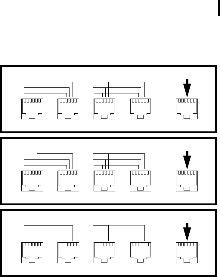
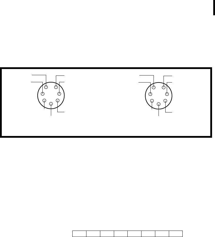
DESCRIPTION All values are 8 bits and must be converted accordingly, depend-
ing on the sensor connected. Figure 4 shows the placement of var-
ious inputs on the connectors.
Figure 4. A730 Connector Inputs
Note: If no Y-boxes are installed, the values sampled on channels 1
to 7 will be duplicated on channels 8 to 14. The drawing
above does not imply that all the Y-boxes must be in place.
In fact, adding the third Y-box makes little sense because
only one analog input can be duplicated on the RAIN con-
nector.
EXTENDED EXTENDED DEFAULT DEFAULT COMMON
Analog11
Analog12
Analog13
Analog4
Analog5
Analog6
From WIND (A730MD)
Y-box #1
EXTENDED EXTENDED DEFAULT DEFAULT COMMON
Analog8
Analog9
Analog10
Analog1
Analog2
Analog3
From SENSOR (A730MD)
Y-box #2
EXTENDED EXTENDED DEFAULT DEFAULT COMMON
Analog14 Analog7
From RAIN (A730MD)
Y-box #3

CHAPTER 3
Advanced Functions
42
The RF level is nonlinear and results from a table (which you can
get from Adcon as an ASCII file). The value of the battery can be
computed as follows:
The digibyte is essentially the reflection of several inputs or internal
status bits on the A730MD; its structure is described below:
For more details, refer to the user manual for the A730MD device
(addVANTAGE A730).
The A720 (addIT) Frames
The addIT uses a reduced frame type (38). No adapter use for
extending the inputs is possible.
Type 38
SIZE 14 (including the type byte).
FORMAT struct tlg_type38 {
BYTE RF_LevelIn;
BYTE RF_LevelOut;
BYTE DigiByte;
BYTE PulseCounter0;
BYTE PulseCounter1;
BYTE BatteryLevel;
BYTE Analog1;
BYTE Analog2;
BYTE Analog3;
BYTE Analog4;
BYTE Analog5;
BYTE Analog6;
BYTE Reserved;
};
Batt V[]
BatteryLevel 20•
255
----------------------------------------------=
B7 B6 B5 B4 B3 B2 B1 B0
S.C. AUX:4 N.U. RAI:3 RAI:4 AUX:2 AUX:3 AUX:5
S.C. = Solar Cell status N.U. = Not used RAI = Rain AUX = Aux
CHAPTER 3
Operations at the Application Level
43
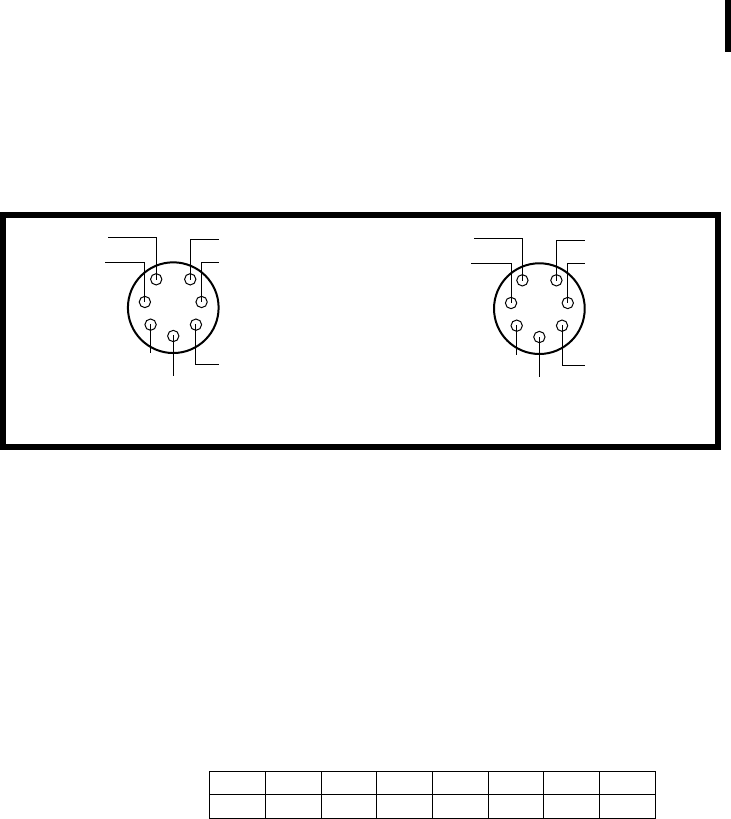
DESCRIPTION All values are 8 bits and must be converted accordingly, depend-
ing on the sensor connected. Figure 5 shows the placement of var-
ious inputs on the connectors.
Figure 5. A720 Connector Inputs
The RF level is nonlinear and results from a table (which you can
get from Adcon as an ASCII file). The value of the battery can be
computed as follows:
The digibyte is essentially the reflection of several inputs or inter-
nal status bits on the A720; its structure is described below:
For more details, refer to the user manual for the A720 device.
The A723 (addIT series 3) Frames
The addIT series 3 implements currently two frame types, depend-
ing on the compatibility mode flag: 38 (described on page 42) and
39. For more details about the compatibility flag, refer to the A720
series user manual.
There is, however, a fundamental difference between frame 39 and
the previously described data frames. The A723 samples the ana-
log values with 10-bit resolution and stores them as 12-bit values.
Analog1
Analog2
Analog3
Ground
Power
DIG0
PulseCounter0
1
2
3
4
5
67
Analog4
Analog5
Analog6
Ground
Power
DIG1
PulseCounter1
1
2
3
4
5
67
I/O A I/O B
A720
Batt V[]
BatteryLevel 20•
255
----------------------------------------------=
B7 B6 B5 B4 B3 B2 B1 B0
S.C. res res res res res DIG1 DIG0
S.C. = Solar Cell status res = reserved

CHAPTER 3
Advanced Functions
44
Also, the A723 contains two 16-bit pulse counters, that is, it has
more data to send. Due to the limited space available and to mini-
mize the radio traffic, the frames are slightly compressed, in that six
12-bit values are packed in 9 bytes.
Type 39
SIZE 22 (including the type byte).
FORMAT struct tlg_type37 {
BYTE RF_LevelIn;
BYTE RF_LevelOut;
BYTE DigiByte;
WORD PulseCounter0;
WORD PulseCounter1;
BYTE BatteryLevel;
BYTE Analog[9];
};
DESCRIPTION The analog values are 12 bits and must be converted accordingly,
depending on the sensor connected, while the pulse counters are
16-bit values. Only the RF and battery levels are 8-bit values.
Analog[9] is an array of 9 unsigned bytes that is the result of
packing the six 12-bit values. These are the values returned by the
internal A/D converter from the respective I/O connectors.
Note: The integers (16-bit values) are sent using the big endian
convention, that is, first the most significant byte and then
the least significant byte.
The packing mechanism is shown in Figure 6.
Figure 6. Type 39 Frame Compression
Six 16-bit values
8-bit packed values
Analog1 Analog2 Analog3 Analog4
12 bits 12 bits 12 bits 12 bits
Byte 0 Byte 1 Byte 2 Byte 3 Byte 6Byte 5Byte 4 Byte 7 Byte 8
etc....
000
0
CHAPTER 3
Operations at the Application Level
45
Note: Only Analog1 to Analog6 are packed; the 16-bit Pulse
Counters are not.
Figure 7 shows the placement of various inputs on the connectors.
Figure 7. A723 Connector Inputs
The RF level is nonlinear and results from a table (which you can
get from Adcon as an ASCII file). The value of the battery can be
computed as follows:
The digibyte is essentially the reflection of several inputs or inter-
nal status bits on the A723; its structure is described below:
For more details, refer to the user manual for the A723 device.
The A733 (addWAVE) Frames
The addWAVE currently implements only one frame type (37). The
A733 samples the analog values with 10-bit resolution and stores
them as 12-bit values. Also, the A733 contains built-in logic to
sample 12 different analog inputs, as well as four 16-bit pulse
counters—all in all, substantially more data. Due to the limited
space available and in order to minimize the radio traffic, the
frames are slightly compressed, in that twelve 12-bit values are
packed in nine 16-bit words.
Analog4
Analog5
Analog6
Ground
Power
DIG1
PulseCounter1
1
2
3
4
5
67
Analog1
Analog2
Analog3
Ground
Power
DIG0
PulseCounter0
1
2
3
4
5
67
I/O A I/O B
A723
Batt V[]
BatteryLevel 20•
255
----------------------------------------------=
S.C. res res res DIG1 DIG0
b0
b7
S.C. = Solar Cell status res = reserved
res res

CHAPTER 3
Advanced Functions
46
Type 37
SIZE 31 (including the type byte).
FORMAT struct tlg_type37 {
BYTE RF_LevelIn;
BYTE RF_LevelOut;
BYTE DigiByte;
WORD PulseCounter0;
WORD PulseCounter1;
WORD PulseCounter2;
WORD PulseCounter3;
BYTE BatteryLevel;
BYTE Analog[18];
};
DESCRIPTION The analog values are 12 bits and must be converted accordingly,
depending on the sensor connected, while the pulse counters are
16-bit values. Only the RF and battery levels are 8-bit values.
Analog[18] is an array of 18 unsigned bytes that is the result of
packing the twelve 12-bit values. These are the values returned by
the internal A/D converter from the respective I/O connectors.
Note: The integers (16-bit values) are sent using the big endian
convention, that is, first the most significant byte and then
the least significant byte.
The packing mechanism is shown in Figure 8.
Figure 8. Type 37 Frame Compression
Note: Only Analog1 to Analog12 are packed; the 16-bit Pulse
Counters are not.
Twelve 16-bit values
8-bit packed values
Analog1 Analog2 Analog3 Analog4
12 bits 12 bits 12 bits 12 bits
Byte 0 Byte 1 Byte 2 Byte 3 Byte 6Byte 5Byte 4 Byte 16 Byte 17
etc....
000
0
CHAPTER 3
Operations at the Application Level
47
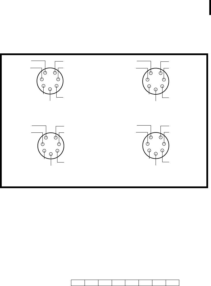
Figure 9 show the placement of various inputs on the connectors.
Figure 9. A733 Connector Inputs
The RF level is nonlinear and results from a table (which you can
get from Adcon as an ASCII file). The value of the battery can be
computed as follows:
The digibyte is essentially the reflection of several inputs or inter-
nal status bits on the A733; its structure is described below:
For more details, refer to the user manual for the A733 device.
Analog4
Analog5
Analog6
Ground
Power
DIG1
PulseCounter1
1
2
3
4
5
67
Analog1
Analog2
Analog3
Ground
Power
DIG0
PulseCounter0
1
2
3
4
5
67
I/O A I/O B
A733
Analog7
Analog8
Analog9
Ground
Power
DIG2
PulseCounter2
1
2
3
4
5
67
I/O C
Analog10
Analog11
Analog12
Ground
Power
DIG3
PulseCounter3
1
2
3
4
5
67
I/O D
Batt V[]
BatteryLevel 20•
255
----------------------------------------------=
S.C. res res res DIG3 DIG2 DIG1 DIG0
b0
b7
S.C. = Solar Cell status res = reserved

CHAPTER 3
Advanced Functions
48
Frame Parsing Example
To better understand how the retrieved frames must be processed,
this section provides an example of such processing. Let’s suppose
that we used the GETBLOCK command and retrieved a block of
frames of type 37. After parsing the block, we separate it into indi-
vidual frames as described in “GETBLOCK” on page 29. Because
all the frames are treated identically, we will show you how to inter-
pret only one of them from the block. The frame looks something
like this:
02066411312A1F25FF7B7F0000000000000000590016AC6B0000
000000A6D5E81C40000000000206
Separating the date/time, frame type and size, and the data seg-
ment, we get this:
020664: Date (2/6/00)
11312A: Time (17:49:42)
1F: Size (31 bytes)
25: Frame type (37)
FF7B7F0000000000000000590016AC6B0000000000A6D5E81C40
00000000: Data
Using the description of frame 37, we can parse the data segment.
To show this more easily, we will rewrite the frame with spaces
inserted between different elements:
FF 7B 7F 0000 0000 0000 0000 59 001 6AC 6B0 000 000
000 A6D 5E8 1C4 000 000 000
Now we can easily map the elements onto the frame 37 structure:
FF: RF in
7B: RF out
7F: Digibyte
0000: PulseCounter0
0000: PulseCounter1
0000: PulseCounter2
0000: PulseCounter3
59: BatteryLevel
001: Analog1
6AC: Analog2
6B0: Analog3
000: Analog4
000: Analog5
000: Analog6
A6D: Analog7
5E8: Analog8
1C4: Analog9
000: Analog10
000: Analog11
000: Analog12
The last step is to convert the analog values to actual engineering
units. This is easily accomplished if we know what sensor is con-
nected to each input of the RTU, and its conversion equation. Let’s

CHAPTER 3
Operations at the Application Level
49
assume that a temperature sensor is connected to the Analog7
input. Then:
Note that 2669 is A6D converted to decimal while the -40 was nec-
essary because the standard Adcon temperature sensor has a
range from -40 to 60 ºC.
Similarly, the battery level can be computed as follows:
Note here that we had to deal with an 8-bit value (59 hex = 89 dec-
imal), so the divider is 255, while the previous example was based
on a 12-bit conversion and the divider was 4095.
Temp °C[]
2669 100u
4095
------------------------- 4 0– 25.17==
Batt V[]
89 20u
255
---------------- 6 . 9 8==

CHAPTER 3
Advanced Functions
50