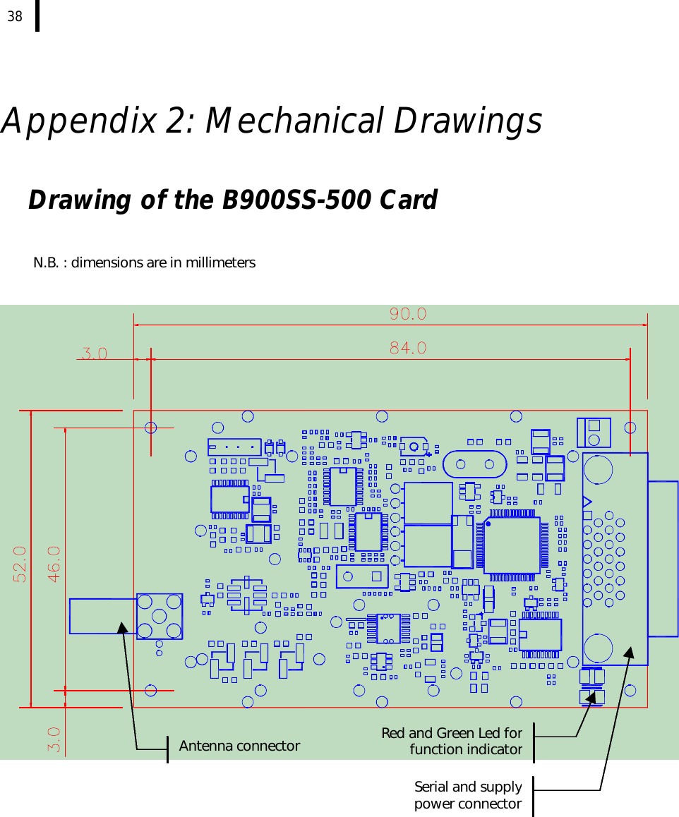
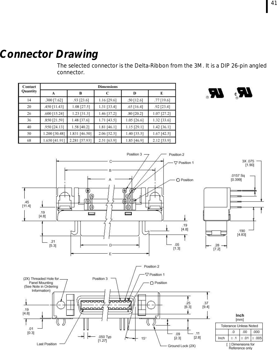
Adcon Telemetry B900SS-500 FM Radio Transceiver Module User Manual English
Adcon Telemetry Inc FM Radio Transceiver Module English
UserManual.wiki
>
Adcon Telemetry
>
B900SS 500 User Manual
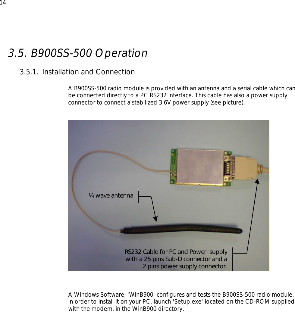
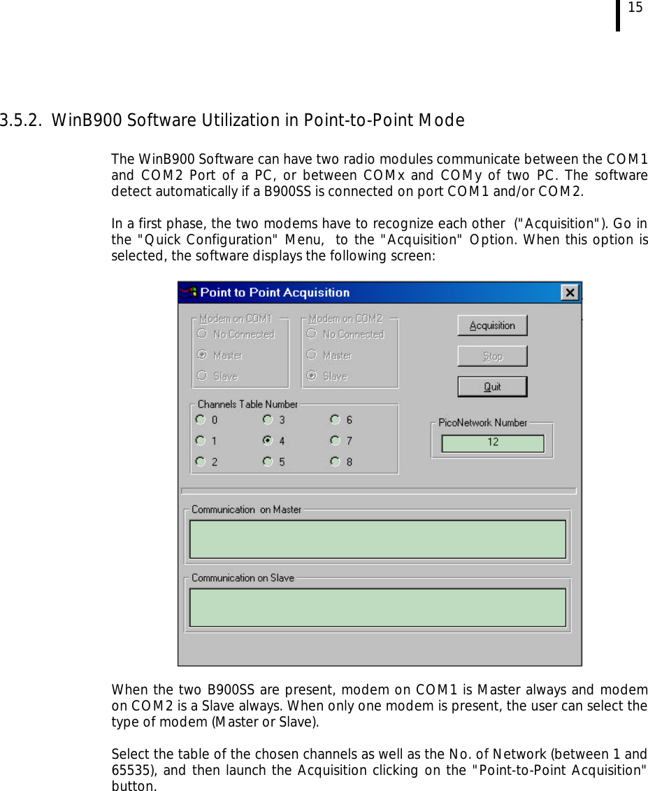
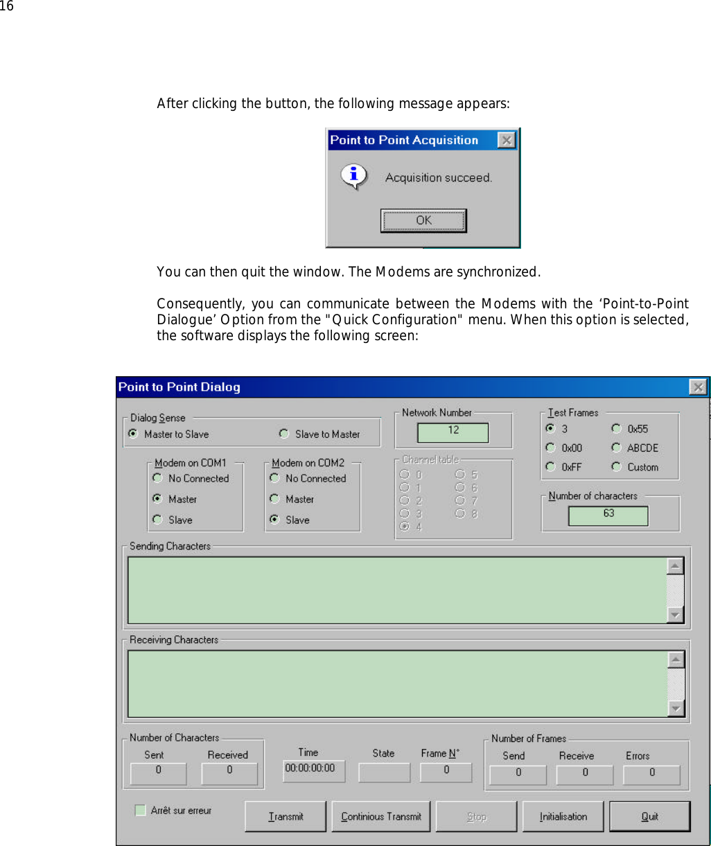
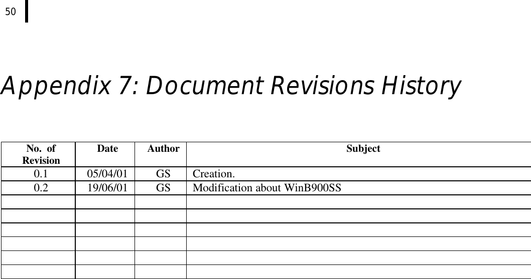
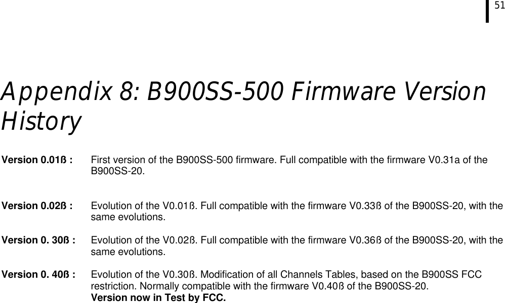
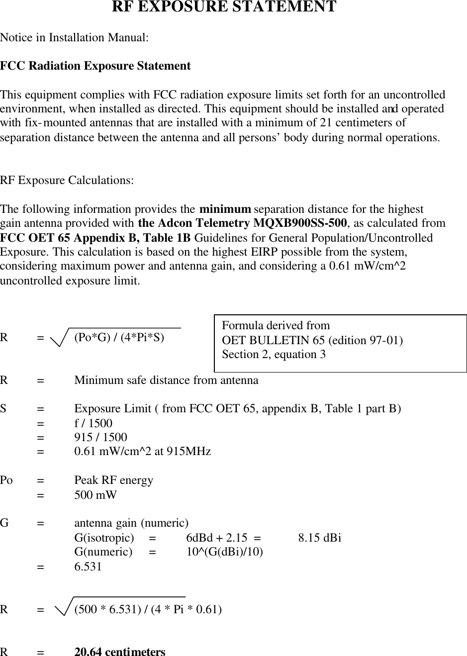
Users Manual
Navigation menu
Upload a User Manual
Namespaces
Wiki Guide
HTML
PDF
Info
Views
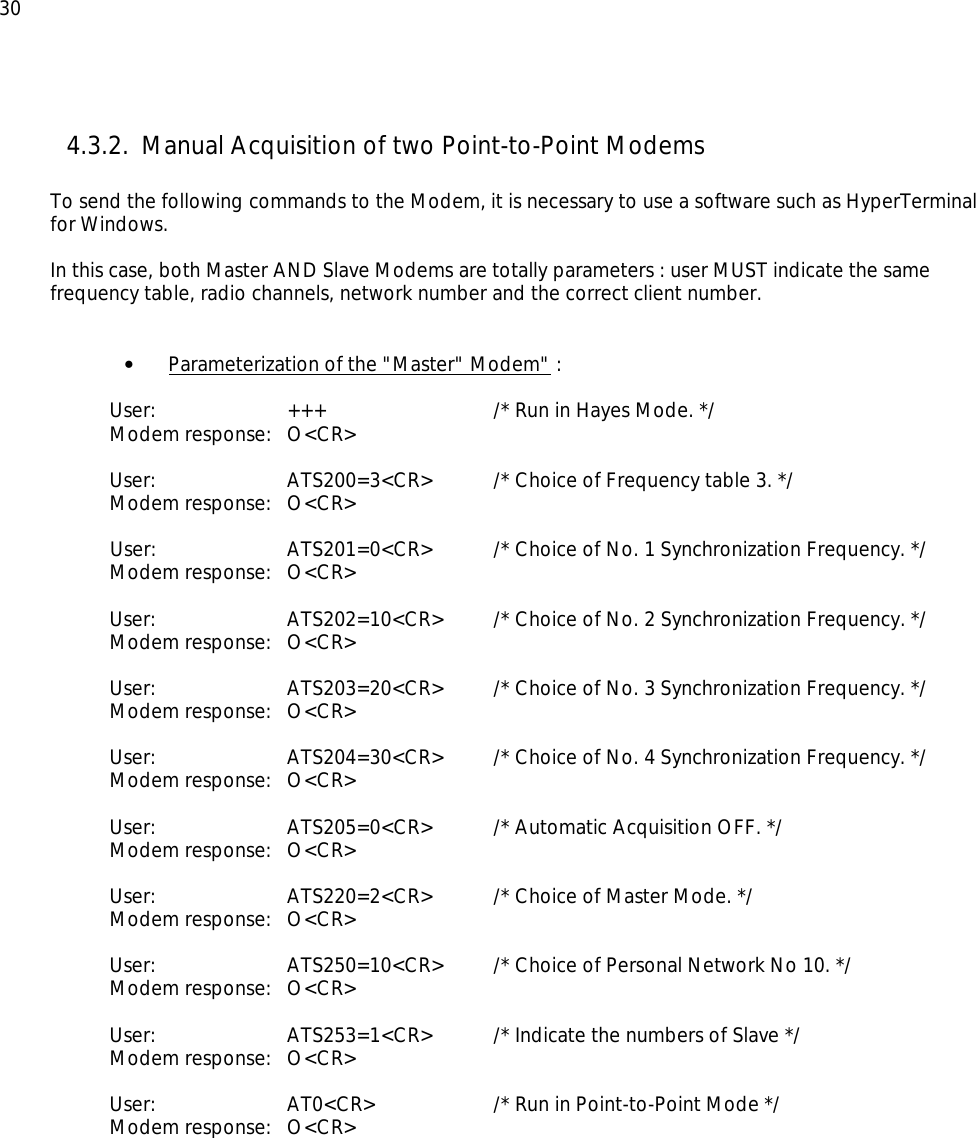
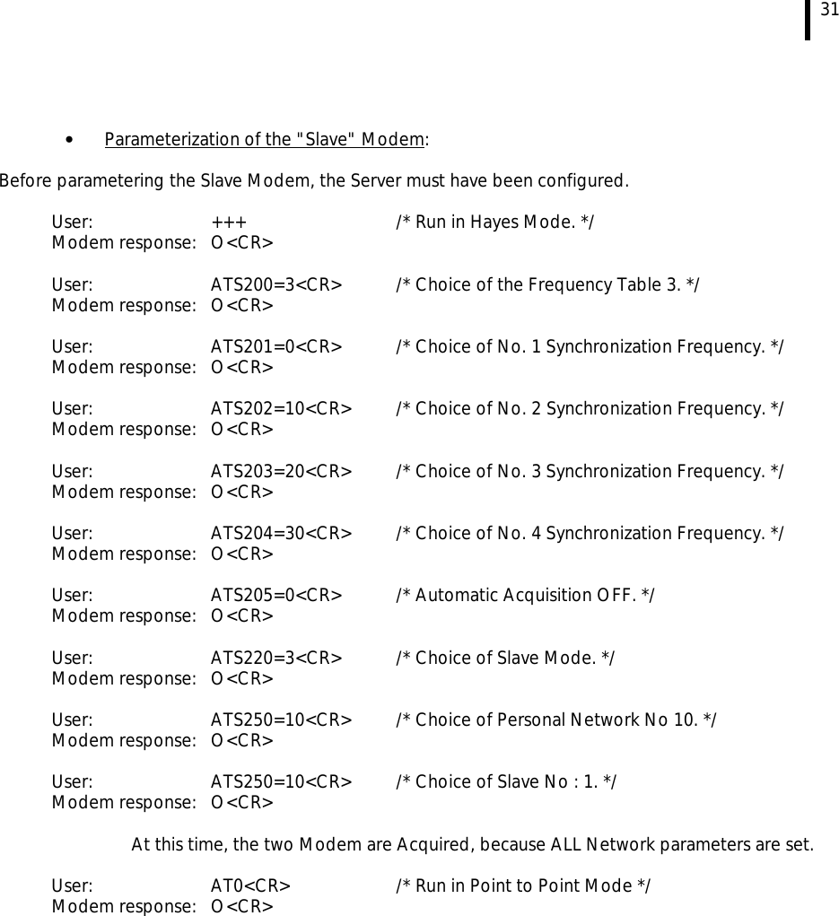
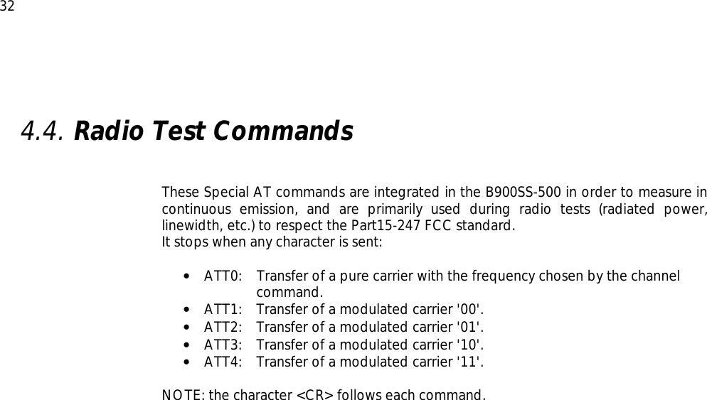
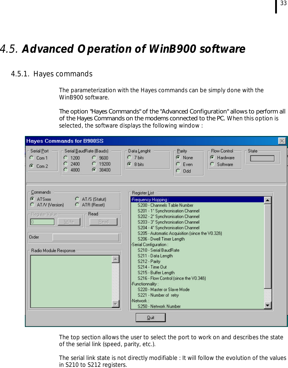
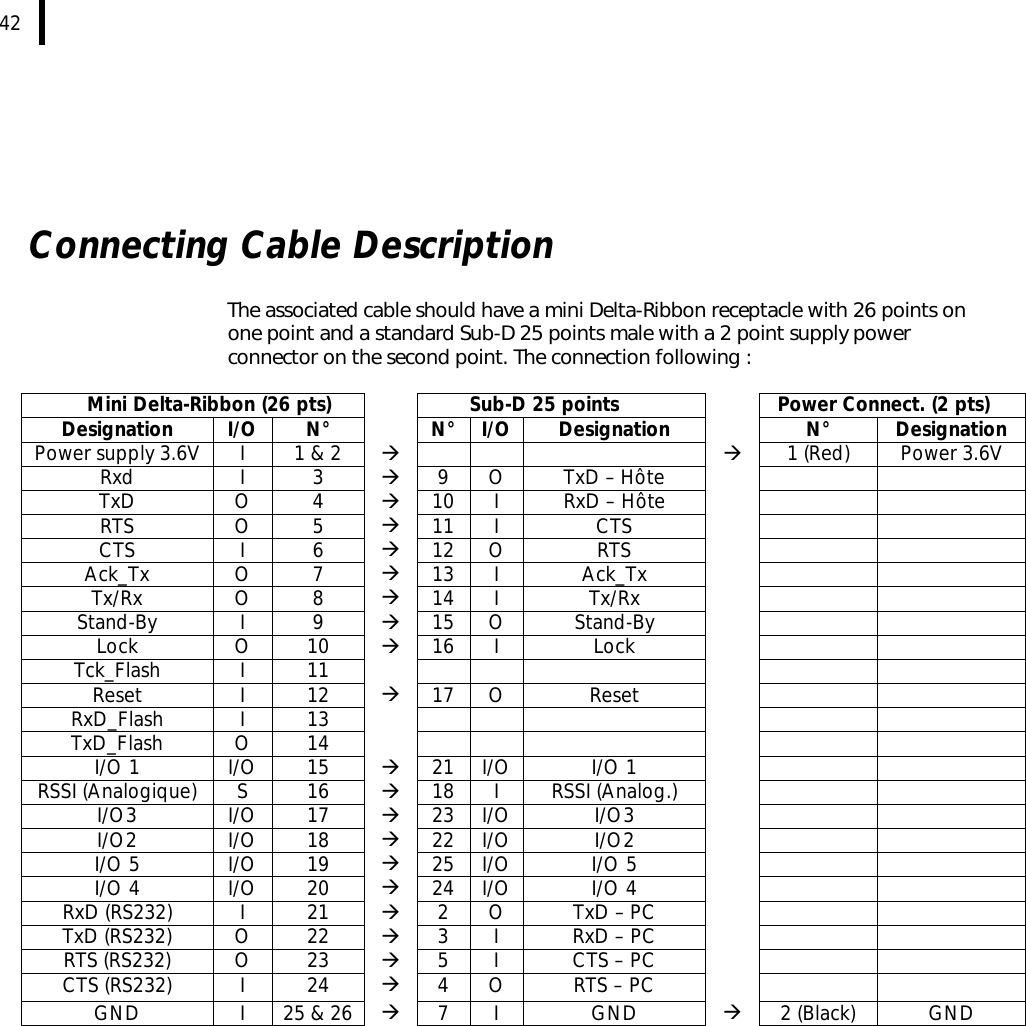
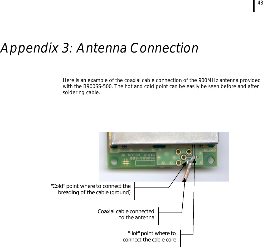
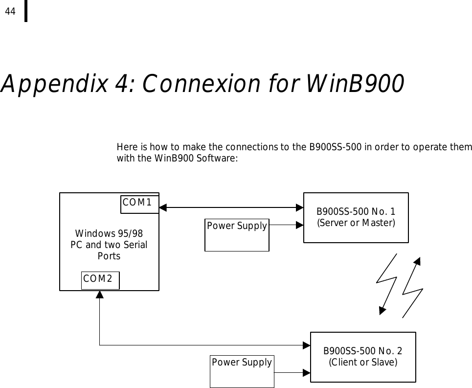
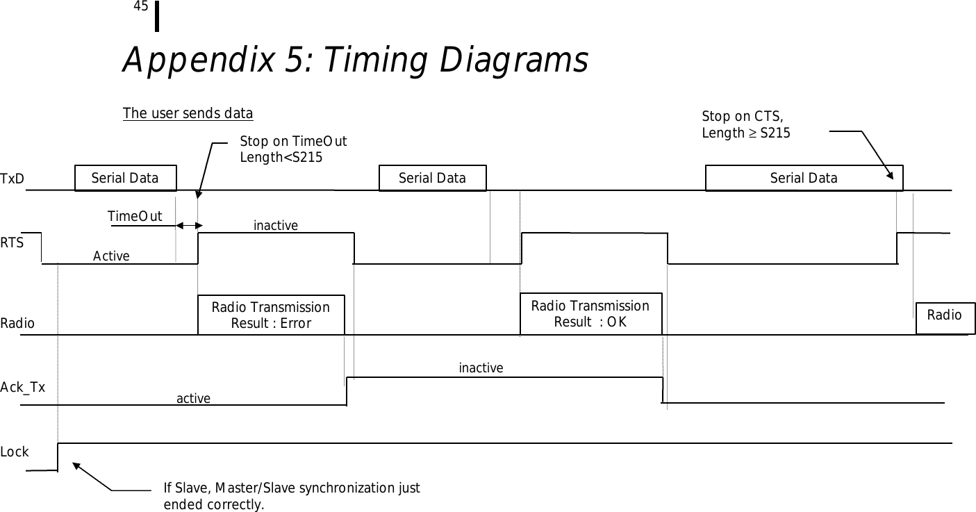
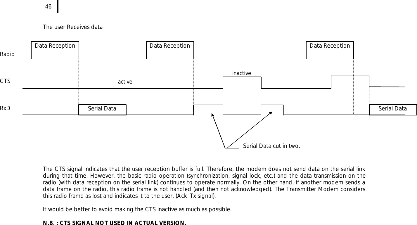
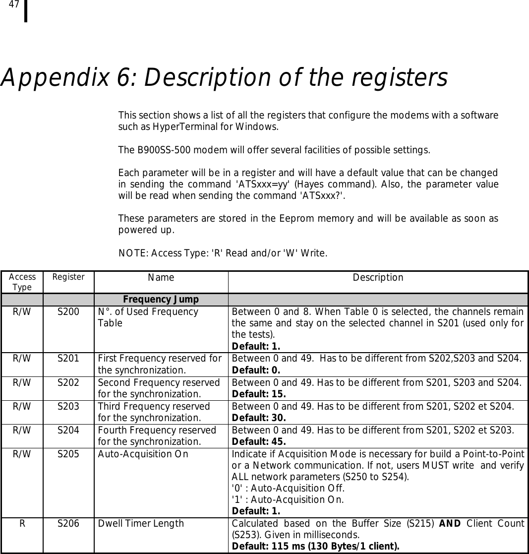
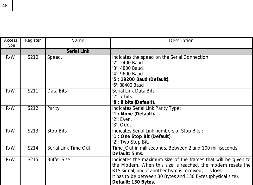
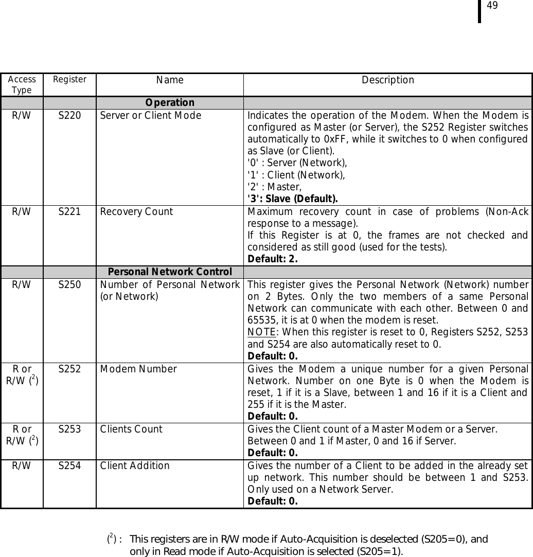
User Manual
Discussion / Help
Navigation