Adcon Telemetry B900SS-500 FM Radio Transceiver Module User Manual English
Adcon Telemetry Inc FM Radio Transceiver Module English
Users Manual
Technical Manual
EDITION: 0.2
UPDATED: 18/06/2001
B900SS-500
Radio Modem Card
Spread Spectrum
(FCC Part15.247)

2
ADCON. AG
Les Cardoulines - Bâtiment B4
1360 route des Dolines
06560 Valbonne
Sophia Antipolis - France
Tel 33 (0)4 97 21 33 10
Fax 33 (0)4 97 21 33 11
Internet Site
http://www.adcon.at
E-mail
info@adcon.com
The information within this document may be modified without notice. No part of this manual
can be duplicated or transferred, electronically or mechanically in any way, without ADCON
AG.'s strict and written consent.

3
INDEX
Chapter 1. Objective....................................................................................................................5
Chapter 2. Module introduction..................................................................................................6
2.1. Description................................................................................................................................. 6
2.2. Specifications............................................................................................................................. 7
2.2.1. General.................................................................................................................................................. 7
2.2.2. Specifications of the B900SS-500 .......................................................................................................... 7
2.2.3. Schematic.............................................................................................................................................. 8
2.3. Available Configuration............................................................................................................ 9
2.3.1. Software Configuration.......................................................................................................................... 9
2.3.2. Hardware Configuration......................................................................................................................... 9
2.3.3. Antennas ............................................................................................................................................. 10
2.3.3.1. General............................................................................................................................................ 10
Chapter 3. Basic Operation.......................................................................................................11
3.1. General .................................................................................................................................... 11
3.2. "Hayes" Mode......................................................................................................................... 11
3.3. "Point-to-Point" Mode............................................................................................................ 12
3.4. "Network" Mode..................................................................................................................... 13
3.5. B900SS-500 Operation ............................................................................................................ 14
3.5.1. Installation and Connection.................................................................................................................. 14
3.5.2. WinB900 Software Utilization in Point-to-Point Mode......................................................................... 15
3.5.3. Use of the WinB900 Software in Network Mode.................................................................................. 19
3.5.4. Use of the "Terminal" or "HyperTerminal" Software............................................................................ 22

4
Chapter 4. Advanced Operation................................................................................................23
4.1. General..................................................................................................................................... 23
4.2. "Hayes" Protocol Commands................................................................................................. 24
4.2.1. General................................................................................................................................................24
4.2.2. Description of the standard commands .................................................................................................25
4.2.3. Registers Description ........................................................................................................................... 27
4.3. Operation Example.................................................................................................................. 28
4.3.1. Automatic Acquisition of two Point-to-Point Modems.......................................................................... 28
4.3.2. Manual Acquisition of two Point-to-Point Modems ..............................................................................30
4.4. Radio Test Commands ............................................................................................................ 32
4.5. Advanced Operation of WinB900 software ............................................................................ 33
4.5.1. Hayes commands.................................................................................................................................33
4.5.2. Test Commands ................................................................................................................................... 35
Appendix 1: Schematic Diagram..................................................................................................37
Appendix 2: Mechanical Drawings..............................................................................................38
Drawing of the B900SS-500 Card......................................................................................................... 38
Interface Signals ................................................................................................................................... 39
Connector Drawing............................................................................................................................... 41
Connecting Cable Description.............................................................................................................. 42
Appendix 3: Antenna Connection ................................................................................................43
Appendix 4: Connexion for WinB900 ..........................................................................................44
Appendix 5: Timing Diagrams .....................................................................................................45
Appendix 6: Description of the registers ......................................................................................47
Appendix 7: Document Revisions History....................................................................................50
Appendix 8: B900SS-500 Firmware Version History...................................................................51

5
Chapter 1. Objective
The objective of this document is to present the features and the application of the
B900SS-500 radio module.
The operation of this module is divided into two chapters:
• The ‘Basic Operation’ chapter describes the Module operating modes and allows
the user to learn the WinB900 Software in walking through it.
• The ‘Advanced Operation’ is especially for users that want to program the
module directly. It presents all the available commands.

6
Chapter 2. Module introduction
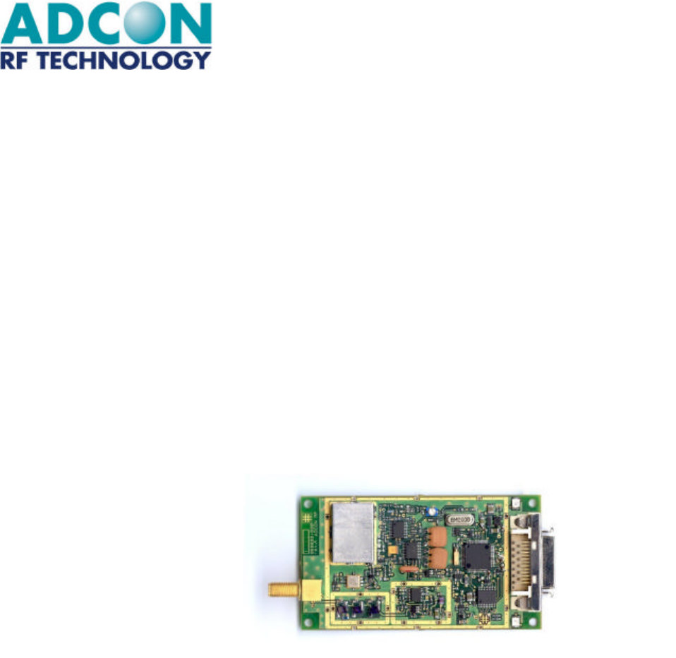
2.1. Description
The B900SS-500 is an FM radio transceiver with frequency hopping using an F.S.K
modulation. The receiver is of a super beat oscillator type with heterodyning. It
operates on the 902-928 MHz band and, therefore, is within U.S. FCC part 15.247
standard.
Using the frequency synthesis, it has a maximum of 50 channels spaced by 200 kHz
and can communicate with equipment via a serial interface with RS-232 standard and
TTL levels.
The serial link is completely programmable from 2400 up to 38400 Baud. The radio
rate is established at 40 KBits/s.
The B900SS-500 uses the most recent technology of flash memory microcontroller,
which allows the user to update or to load new features through the serial link.
Many parameters are programmable through the serial link and the default
configuration is memorized in a Flash Bank with the 'ATO' order.
At each activation, the radio modem component is programmed with its configuration
parameters (Channel, Speed, Protocol, etc.).
The default data are: RS-232 connection at 19.200 Baud, 8 bits, 1 stop bit, no parity,
Frequency Table 1, Client modem.
All these parameters are accessible and modifiable with HAYES (or AT) commands.

7
2.2. Specifications
2.2.1. General
The B900SS-500 is a radio card component that receives and transmits data according
to a frequency table selected by the user.
2.2.2. Specifications of the B900SS-500
Radio Part :
• Electronic :
Frequency: 902 to 928 MHz (FCC part 15-247).
Number of channels: 50, channel 0 to 49.
Channel selection: Frequency hopping, according to a random
table of 50 channels. 8 tables are stored in
Flash memory.
Radio rate: 40 KBits/s.
Modulation/Demodulation: FSK (Frequency Shift Keying).
Bit encoding: Quad Frequencies encoding.
RF sensitivity: -97 dBm (± 2 dB) at 50 Ohms.
RF power: +27 dBm (500 mW) (± 2 dB) over 50 Ohms.
Error rate: <10-4 bytes to -95 dBm.
Saturation: Two modules communicate at 0 dBm.
Operation Temp.: Standard operation : 14°F to +131°F.
Storage Temp.: -40°F to +176°F.
Relative humidity: From 20% to 90% RH (without condensation).
• Performance range :
Length of communication : 500 to 1,000 Feet in difficult environment
(Ex. : buildings, reinforced concrete),
3,400 to 4,500 Feet in open environment
(Ex : Ground level),
11,000 Feet in view and in height
(Ex: between buildings).
Obstacles Impact : Walls, trees, obstacles can strongly reduce the
range.

8
Digital Part :
• Electronic :
Processor: FLASH Microcontroller
Programming: Upload and download with a PC through the RS232
serial link and a specific cable.
Program Memory : 16 Kbytes of FLASH
Data Memory: 512 bytes of RAM for stack and data
Flash Data Memory : 256 bytes for all parameters (Registers).
Serial Link: 2400 to 38400 Baud, NRZ format, 5 volts TTL ou
RS232 level with TxD, RxD, CTS and RTS.
• Power Supply :
Supply voltage: 3,6V monitored (± 5%).
MAX RATING : 4V.
Consumption: Receive Transmit Sleep
<50mA <900mA <15µA
• Hayes Commands :
The user can program all the parameters. A Windows programming
software is supplied "on-line" with documentation support. (See AT
commands).
Examples of Hayes commands:
Serial: Serial link rate, parity, bit count, stop bit count, Serial Time-
out, …
Radio: Channels table selection, retry count, …
Mode: Point to Point, Network (future), Stand-by, etc.
Dimensions :
Weight: <50 g (without antenna).
Dimensions: 107 x 52 x14 mm (without antenna).
Connectors: 1x Delta-Ribbon 26 pins receptacle from 3M.
2.2.3. Schematic
See Appendix 1 for the principle schematics and the physical description of the card.

9
2.3. Available Configuration
2.3.1. Software Configuration
The B900SS-500 has 3 operating modes managed by the WinB900 Software (See
Chapter 3) :
• "Hayes",
• Point-to-Point,
• Network.
2.3.2. Hardware Configuration
All the B900SS product radio modules are delivered with the necessary software for
operation. For more information, refer to Appendix 4.
With each radio module, the following is available :
• Series of programming ASCII messages to integrate the radio modems with a
serial link (Terminal & .
• A Windows configuration and test software programming the radio modules
and testing the links (quality, distance, shadow area, etc.).
• A set of reference material available in CD-ROM.
10
2.3.3. Antennas
2.3.3.1. General
The radio module beams signals and communicates with its antenna, which is
absolutely essential.
If it has a defective antenna, if this antenna fails to balance or is installed in a noisy
environment, it can lead to a bad result.
For more information, refer to Appendix 3.
Purpose :
Ä ½ length wave model Omni +3dBi antenna with a short coaxial cable.
Ä Directive +6dBi antenna with a short coaxial cable.

11
Chapter 3. Basic Operation
3.1. General
The B900SS-500 can operate with three data communication modes:
• "Hayes": inspired from the standard Hayes for voice modems, it is used to
program the modem's parameters.
• "Point-to-Point": Two B900SS-500 replace a cable (the Half-duplex operation
copies the function of an RS-485 cable). This mode automatically handles the data
security (encapsulation, iterations, etc.)
• "Network": Several B900SS-500 can work together, in accordance with a
Client/Server structure. A Server will then be able to handle up to 16 clients
simultaneously.
3.2. "Hayes" Mode
The Hayes commands used by the radio module are in conformity with the Hayes
protocol standard used for the voice modems. This protocol is based on the following
principle: A data frame always starts with the two ASCII characters "AT" for
"ATtention". The commands follow and are coded on one or several characters
eventually with additional data.
Since the B900SS-500 does not operate exactly like a voice modem, it includes
additional "AT" codes.
These commands are principally used to read and write the data in the configuration
registers stored in Flash.
12
3.3. "Point-to-Point" Mode
In this mode, two B900SS-500 Modems can communicate together without getting
any interference with other Modems.
For this purpose, their work is synchronized and constantly jumping frequency,
avoiding interference with another transmitter: if one or more channels are busy, the
data will be transmitted through another channel.
On the other hand, a "Personal Network" owns each set of modem. The data used for
a "Personal Network" cannot be intercepted by another "Personal Network". Each
"Personal Network" owns a Master, which handles the communication
(synchronization, priority, etc.) and a Slave that obeys its Master.
The first synchronization is named "Acquisition", and lets a Slave get acquainted with
its Master (No. of Personal Network, Frequency Table used, etc.). Eventually, at each
powered reset, the Slave will synchronize, then later be able to communicate with its
Master. A "Lock" signal shows if a Slave has been synchronized with its Master or not.
Eventually, this synchronization is maintained all along the Master/Slave Dialogue.
A hardware flow control (RTS/CTS) is present on the Modems serial link in order to let
the user know that the buffer (130 characters) starts to saturate. The alarm level is by
default 130 characters and can be programmed through the S215 Register.
Finally, an Ack_Tx signal, synchronized on the RTS signal, allows the transmitter user
to know if the receiver user has received a data frame or not.
For more specific information and to get the Time Series Charts, see the following
chapter ("Advanced Part") and the Appendix 5.

13
3.4. "Network" Mode
In this mode, several B900SS-500 Modems are able to communicate with each other.
Therefore, they constitute a Network handled by a Server Modem that can hold up to
16 Client Modems.
The acquisition procedures, the modems synchronization and the RTS/CTS and
Ack_Tx signals handling are the same as for the "Point-to-Point" Mode.
On the other hand, when a frame is sent, it is necessary that a character indicating the
receiver modem number precedes the data frame. Also, in receiving the frame, a
character preceding this frame indicates the transmitter modem.
14
3.5. B900SS-500 Operation
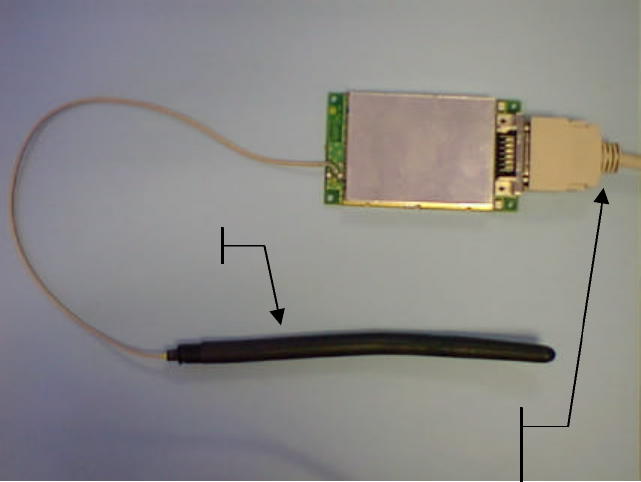
3.5.1. Installation and Connection
A B900SS-500 radio module is provided with an antenna and a serial cable which can
be connected directly to a PC RS232 interface. This cable has also a power supply
connector to connect a stabilized 3,6V power supply (see picture).
A Windows Software, 'WinB900' configures and tests the B900SS-500 radio module.
In order to install it on your PC, launch 'Setup.exe' located on the CD-ROM supplied
with the modem, in the WinB900 directory.
¼ wave antenna
RS232 Cable for PC and Power supply
with a 25 pins Sub-
D connector and a
2 pins power supply connector.
15
3.5.2. WinB900 Software Utilization in Point-to-Point Mode
The WinB900 Software can have two radio modules communicate between the COM1
and COM2 Port of a PC, or between COMx and COMy of two PC. The software
detect automatically if a B900SS is connected on port COM1 and/or COM2.
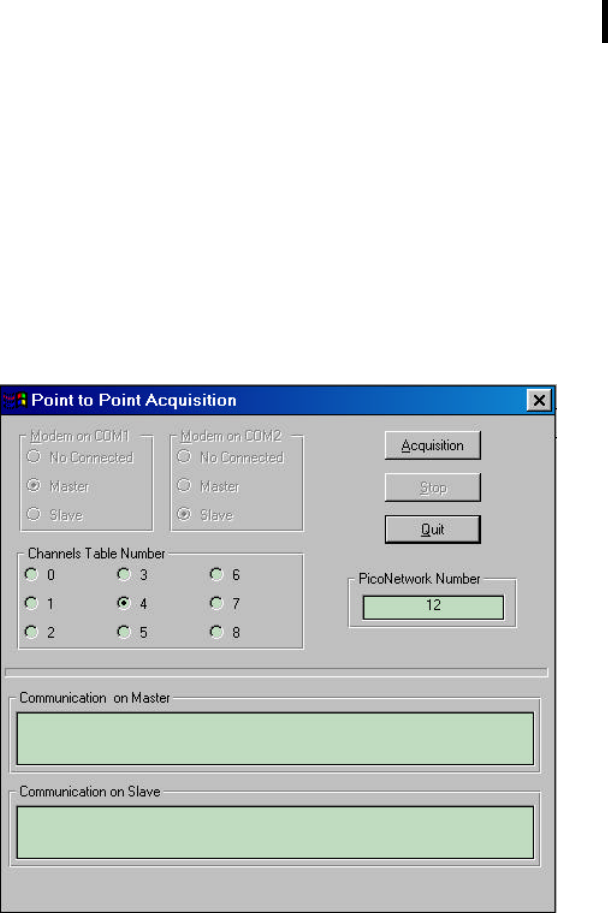
In a first phase, the two modems have to recognize each other ("Acquisition"). Go in
the "Quick Configuration" Menu, to the "Acquisition" Option. When this option is
selected, the software displays the following screen:
When the two B900SS are present, modem on COM1 is Master always and modem
on COM2 is a Slave always. When only one modem is present, the user can select the
type of modem (Master or Slave).
Select the table of the chosen channels as well as the No. of Network (between 1 and
65535), and then launch the Acquisition clicking on the "Point-to-Point Acquisition"
button.
16
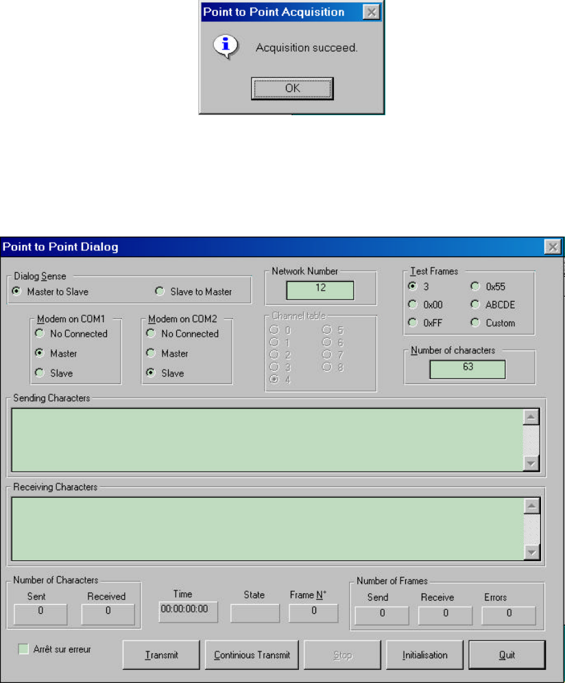
After clicking the button, the following message appears:
You can then quit the window. The Modems are synchronized.
Consequently, you can communicate between the Modems with the ‘Point-to-Point
Dialogue’ Option from the "Quick Configuration" menu. When this option is selected,
the software displays the following screen:

17
The different fields and buttons are described below:
• "Sending Characters" Field
This side of the window sends the data entry.
• "Receiving Characters" Field
This side of the window shows the received data.
• "Test Frames" Selection
This selection allows to select the type of character sent. For example, 0x00
sends a character frame only made of a 0x00 binary character.
If the "Free" frame type is selected, the user can type the frame in the "Sent
Character" field. This frame will then be sent.
• "Dialog Sense" Selection
This selection allows to select the sense of transmission : since Master to Slave or
since Slave to Master.
• "Modem on COMx" Field
This field allows to select if modem is present on port COMx and if, the type of
this Modem : Master or Slave.
• "Characters Count" Field
This field allows to select the character count to be sent if the selected test frame
type is any other than "free".
• Button: "Transmit"
This button sends the frame entered previously to the Characters section to be
sent.
• Button: "Continuous Transmit"
This button sends continuously the frame entered previously to the Data section
to be sent.
• Button: "Initialization"
This button reinitializes all the counter fields (Elapse Time, Character Count,
Frame Count, etc.)
• Button: "Stop"
This button stops a continuous upload.
• Button: "Quit"
This button leaves this window and returns to the main menu.
• "Character Count Sent/Received" Fields
These fields show the sizes of the sent and received frames.
18
• "Elapsed time" Field
This field shows how long it takes the modem to upload the same frame during a
continuous upload.
• "Sent/Received/Corrupted Count" Fields
These fields show the amount of frames correctly uploaded, downloaded or
corrupted (or not received) since the start of a continuous upload.
• "Stop on Error" Selection
This selection stops automatically the continuous upload if a frame is corrupted.
19
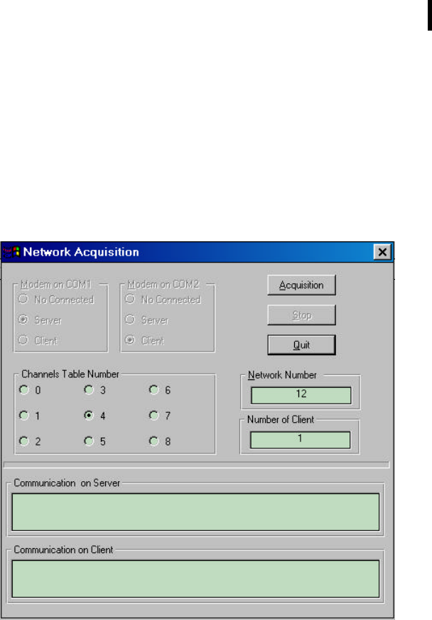
3.5.3. Use of the WinB900 Software in Network Mode
The operating principle is similar to the Point-to-Point Mode.
In a first phase, the two modems have to recognize each other ("Acquisition"). Go in
the "Quick Configuration" Menu, to the "Network Acquisition" option . When this
option is selected, the software displays the following screen:
When the two B900SS are present, modem on COM1 is Server always and modem on
COM2 is a Client always. When only one modem is present, the user can select the
type of modem (Server or Client).
It should be noticed that if the Modem already holds a Network Number and Clients,
these two pieces of information will display in the "Network No." and "Clients
Count". If the Network No. is modified, the Server will then lose all the Clients already
acquired.
20
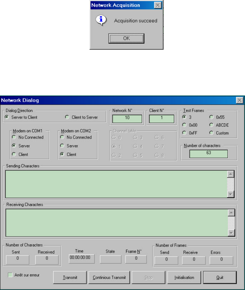
Acquisition can be launched by clicking on the "Acquisition" button. After this, the
following message is displayed :
You can then quit the window. The Modems are synchronized.
You can then communicate between the Modems with the ‘Network Dialogue’ Option
from the "Quick Configuration" Menu. When you pick this option, the software
displays the following :

21
The different fields and buttons are similar to the ones described in the previous
paragraph at the "Point-to-Point Dialogue" window. Only two new fields appear:
• "Network Number"
This field indicates the Network No. in the Server and Client.
• "Client Number"
This field indicates the Modem No. in the Client (if present).
22
3.5.4. Use of the "Terminal" or "HyperTerminal" Software
The B900SS-500 radio modules can also be handled from a Windows "HyperTerminal" or "Terminal" type
communication software.
The software has to be configured, in order to communicate at 19200 Baud, 8 bits, no parity, 1 stop bit through
a Serial link. To start with a correct configuration for HyperTerminal and Terminal, the following directories are
provided :
• "B900-CM1.ht" for "HyperTerminal" on COM1.
• "B900-CM2.ht" for "HyperTerminal" on COM2.
• "B900-CM1.trm" for "Terminal" on COM1.
• "B900-CM2.trm" for "Terminal" on COM2.
In this case, if your modems have already been configured and already been "Acquired", you can send data
frames with these software immediately. Otherwise, refer to Chapter 4 (Advanced Operation) to know how to
use the Registers.

23
Chapter 4. Advanced Operation
4.1. General
The section "Basic Operation" shown us how to operate the B900SS-500 Radio
Module.
This section's objective is to know the module more completely; particularly the Hayes
commands necessary to handle the modem.

24
4.2. "Hayes" Protocol Commands
4.2.1. General
These commands configure the Modem assigning different values in the registers
(S200 and next). They also enable the user to know the state of the registers and the
version of the modem software. These frames can only be sent if the CTS signal is
active except when in Acquisition Mode.
These commands support the 'Hayes' protocol used by the voice Modems. When a
command is sent, it always has to be preceded by the 'AT' characters (ATtention).
When a command has been sent, it always has to be followed by the <CR> character
(carriage return, Hexadecimal 0x13 code).
NOTE: The time slot between two characters of the command has to be inferior to
Time-Out (S214). As a result, the commands have to be sent by block:
A T Command Additive command ... <CR>
The sole exception is the passing command from the Operation Mode in progress to
the Hayes Mode: In this case, the escape code ('+++') has to be followed and
preceded by a silence period that lasts at least the same as time out. In this case only,
the command will neither be preceded by AT, nor followed by <CR>
These commands are described in detail in the next chapter.

25
4.2.2. Description of the standard commands
Here is a description of possible commands :
'+++': Running in Hayes Mode.
This command allows the user to return to Hayes Mode when the
Modem is in "Point-to-Point" ou "Network" Mode. It cannot be
preceded by AT, only by an idle time (blank) that can be set through the
S214 register for the duration.
NOTE : When the Modem runs in "AT" Mode, it is no longer in radio
receiver.
'ATO': Running in "Point-to-Point" or "Network" Mode.
This command allows the user to run the Modem in the Mode according
the S220 Register. To retrieve the "Hayes" Mode, send out the
sequence ‘+++’.
ATTENTION : all registers which are modified by an AT command are
stored on Flash ONLY AFTER this command.
NOTE : this command also automatically leaves the Acquisition Mode.
'ATSn?': Display of the S Number n Register content.
The content of the B900SS-500 operating parameters are found in
named 'S' registers, and are numbered as described in Chapter VII- 3.
Some parameters are standard for all the Hayes Modems; others are
specific to B900SS-500.
(See Table in Appendix 6).
If the requested register is correct, the modem responds: ''Sxxx=yyy"
with xxx: register number and yyy: register content.
If the requested register is incorrect, the modem responds with the error
character 'E' (0x45).
These parameters are saved in EEPROM Memory and automatically
reloaded during a reset or when powered up.
26
'ATSn=m': Assignment to the m Value at the S Register n Number.
Loading of a parameter in a register. This parameter is automatically saved
in Flash Memory AFTER the ATO command.
The n and m values are given in ASCII coded decimals. If the assigned
register is correct, the modem responds with the OK character 'O' (0x4F).
If the assigned register is incorrect or if the value goes over the limits of
this register, the modem responds with the error character 'E' (0x45).
'AT/S': Content Uncoded Display of all Significant Records.
All the Modem significant registers (radio configuration, serial
configuration, operating mode...) are sent on the serial link uncoded,
ready to be displayed using a software such as "Terminal" for Windows.
The response is a list of all the used registers with their value, each
register being separated from the other with the "Carriage Return"
character (CR): "S200=xx<CR>S201=yy<CR>…."
'AT/V': Uncoded Display of the Modem Software Version.
The information on the version number, conception date and the program
CRC are sent to the uncoded serial link, ready to be displayed using a
software such as "Terminal" for Windows.
The response is as follows: "Version B900SS-500 : x.xx<CR>"
'ATMx': Running/Stop the Acquisition Mode.
This command allows to toggle from Normal Mode to Acquisition Mode
and vice-versa, according to the x value. The Modem is in Normal Mode
by default.
Then there is: x = '0' à Normal Mode ('ATO' also operate),
x = '1' à Acquisition Mode.
If the command is given correctly, the modem responds with the OK
character 'O' (0x4F), otherwise with the error character 'E' (0x45).
'ATP': Running in Standby Mode.
This command allows the user to running to Standby Mode. The Modem is
in Normal Mode by default.
If the command is correctly given, the modem responds with the OK
character 'O' (0x4F), otherwise with the Error character 'E' (0x45).
The Modem exit to Standby-Mode for go to Normal Mode with another
character.
N.B : during the Stand-By mode, the Client/Slave modem is de-
synchronized and the wake-up can during between 1 and 5 second (time
for re-acquire the synchronization).

27
'ATR': Parameters Reset.
This command allows the user to reprogram ALL the stored EEPROM
registers and give them their value by default.
If the command is correctly given, the modem responds with the OK
character, 'O' (0x4F), otherwise with the Error character 'E' (0x45).
4.2.3. Registers Description
This section is available in Appendix 6.

28
4.3. Operation Example
4.3.1. Automatic Acquisition of two Point-to-Point Modems
To send the following commands to the Modem, it is necessary to use a software such as HyperTerminal
for Windows.
In this case, only Master Modems are totally parameters and after the Acquisition command, the Master
recognize the Slave, indicate this new table, channels, network and client number.
• Parameterization of the "Master" Modem" :
User: +++ /* Run in Hayes Mode. */
Modem response: O<CR>
User: ATS200=3<CR> /* Choice of Frequency table 3. */
Modem response: O<CR>
User: ATS201=0<CR> /* Choice of No. 1 Synchronization Frequency. */
Modem response: O<CR>
User: ATS202=10<CR> /* Choice of No. 2 Synchronization Frequency. */
Modem response: O<CR>
User: ATS203=20<CR> /* Choice of No. 3 Synchronization Frequency. */
Modem response: O<CR>
User: ATS204=30<CR> /* Choice of No. 4 Synchronization Frequency. */
Modem response: O<CR>
User: ATS205=1<CR> /* Automatic Acquisition ON. */
Modem response: O<CR>
User: ATS220=2<CR> /* Choice of Master Mode. */
Modem response: O<CR>
User: ATS250=10<CR> /* Choice of Personal Network No 10. */
Modem response: O<CR>
User: ATM1<CR> /* Run in Acquisition Mode */
Modem response: O<CR>

29
The user now must configure the Slave Modem. Once this configuration has been done and
the "ATM1" command activated, they acquire themselves and the Master Modem returns:
S252=1<CR> /* Indicates Acquisition done, and N° of Slave */
User: AT0<CR> /* Quit Acquisition and run in Point-to-Point Mode */
Modem response: O<CR>
• Parameterization of the "Slave" Modem:
Before parametering the Slave Modem, the Server must have been configured and must be in Acquisition
Mode.
User: +++ /* Run in Hayes Mode. */
Modem response: O<CR>
User: ATS200=3<CR> /* Choice of the Frequency Table 3. */
Modem response: O<CR>
User: ATS201=0<CR> /* Choice of No. 1 Synchronization Frequency. */
Modem response: O<CR>
User: ATS202=10<CR> /* Choice of No. 2 Synchronization Frequency. */
Modem response: O<CR>
User: ATS203=20<CR> /* Choice of No. 3 Synchronization Frequency. */
Modem response: O<CR>
User: ATS204=30<CR> /* Choice of No. 4 Synchronization Frequency. */
Modem response: O<CR>
User: ATS205=1<CR> /* Automatic Acquisition ON. */
Modem response: O<CR>
User: ATS220=3<CR> /* Choice of Slave Mode. */
Modem response: O<CR>
User: ATS250=0<CR> /* Indicates Virgin Slave (No Client Network N°0). */
Modem response: O<CR>
User: ATM1<CR> /* Run in Acquisition Mode */
Modem response: O<CR>
At this time, the two Modems have to acquire themselves, and the Slave Modem respond
S250=10<CR>S252=1<CR> /* Indicates Acquisition done with Network N°10 and Slave N°
User: AT0<CR> /* Quit Acquisition and run in Point to Point Mode */
Modem response: O<CR>

30
4.3.2. Manual Acquisition of two Point-to-Point Modems
To send the following commands to the Modem, it is necessary to use a software such as HyperTerminal
for Windows.
In this case, both Master AND Slave Modems are totally parameters : user MUST indicate the same
frequency table, radio channels, network number and the correct client number.
• Parameterization of the "Master" Modem" :
User: +++ /* Run in Hayes Mode. */
Modem response: O<CR>
User: ATS200=3<CR> /* Choice of Frequency table 3. */
Modem response: O<CR>
User: ATS201=0<CR> /* Choice of No. 1 Synchronization Frequency. */
Modem response: O<CR>
User: ATS202=10<CR> /* Choice of No. 2 Synchronization Frequency. */
Modem response: O<CR>
User: ATS203=20<CR> /* Choice of No. 3 Synchronization Frequency. */
Modem response: O<CR>
User: ATS204=30<CR> /* Choice of No. 4 Synchronization Frequency. */
Modem response: O<CR>
User: ATS205=0<CR> /* Automatic Acquisition OFF. */
Modem response: O<CR>
User: ATS220=2<CR> /* Choice of Master Mode. */
Modem response: O<CR>
User: ATS250=10<CR> /* Choice of Personal Network No 10. */
Modem response: O<CR>
User: ATS253=1<CR> /* Indicate the numbers of Slave */
Modem response: O<CR>
User: AT0<CR> /* Run in Point-to-Point Mode */
Modem response: O<CR>

31
• Parameterization of the "Slave" Modem:
Before parametering the Slave Modem, the Server must have been configured.
User: +++ /* Run in Hayes Mode. */
Modem response: O<CR>
User: ATS200=3<CR> /* Choice of the Frequency Table 3. */
Modem response: O<CR>
User: ATS201=0<CR> /* Choice of No. 1 Synchronization Frequency. */
Modem response: O<CR>
User: ATS202=10<CR> /* Choice of No. 2 Synchronization Frequency. */
Modem response: O<CR>
User: ATS203=20<CR> /* Choice of No. 3 Synchronization Frequency. */
Modem response: O<CR>
User: ATS204=30<CR> /* Choice of No. 4 Synchronization Frequency. */
Modem response: O<CR>
User: ATS205=0<CR> /* Automatic Acquisition OFF. */
Modem response: O<CR>
User: ATS220=3<CR> /* Choice of Slave Mode. */
Modem response: O<CR>
User: ATS250=10<CR> /* Choice of Personal Network No 10. */
Modem response: O<CR>
User: ATS250=10<CR> /* Choice of Slave No : 1. */
Modem response: O<CR>
At this time, the two Modem are Acquired, because ALL Network parameters are set.
User: AT0<CR> /* Run in Point to Point Mode */
Modem response: O<CR>
32
4.4. Radio Test Commands
These Special AT commands are integrated in the B900SS-500 in order to measure in
continuous emission, and are primarily used during radio tests (radiated power,
linewidth, etc.) to respect the Part15-247 FCC standard.
It stops when any character is sent:
• ATT0: Transfer of a pure carrier with the frequency chosen by the channel
command.
• ATT1: Transfer of a modulated carrier '00'.
• ATT2: Transfer of a modulated carrier '01'.
• ATT3: Transfer of a modulated carrier '10'.
• ATT4: Transfer of a modulated carrier '11'.
NOTE: the character <CR> follows each command.
33
4.5. Advanced Operation of WinB900 software
4.5.1. Hayes commands
The parameterization with the Hayes commands can be simply done with the
WinB900 software.
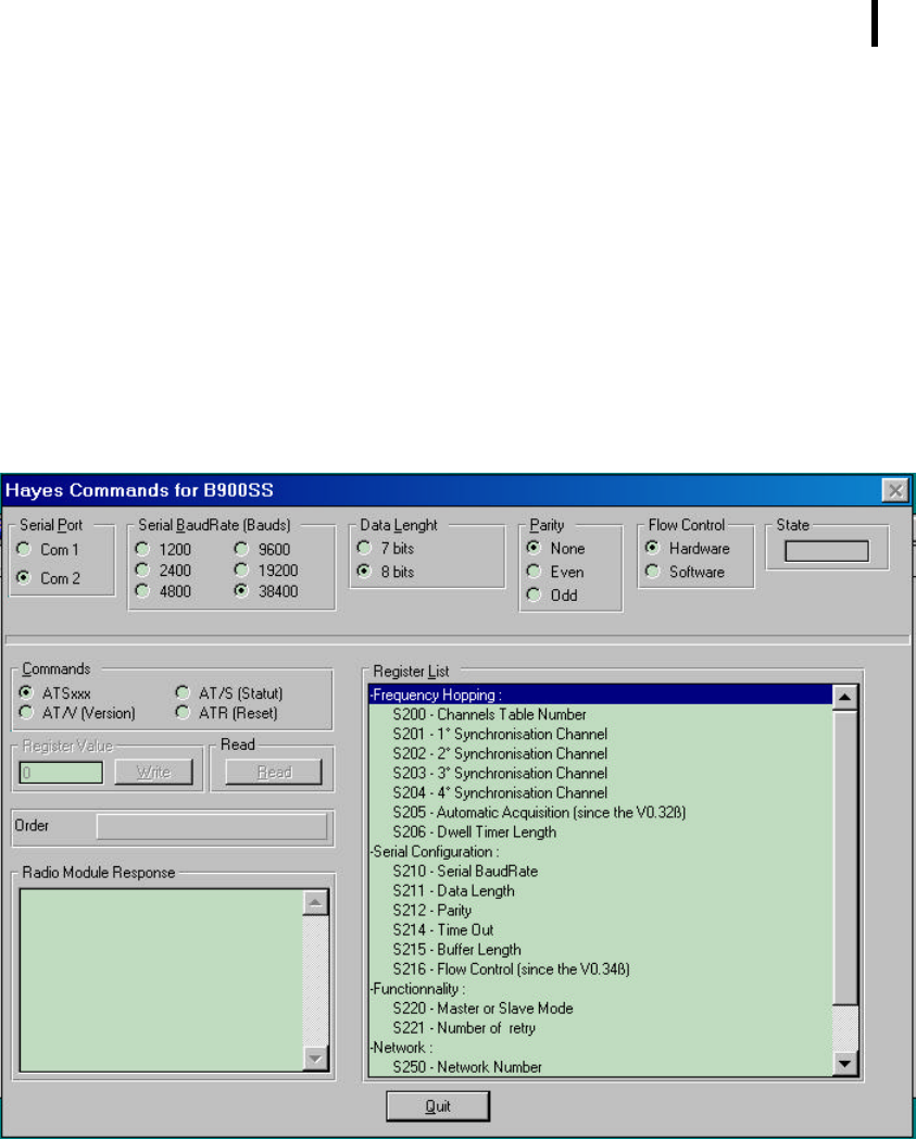
The option "Hayes Commands" of the "Advanced Configuration" allows to perform all
of the Hayes Commands on the modems connected to the PC. When this option is
selected, the software displays the following window :
The top section allows the user to select the port to work on and describes the state
of the serial link (speed, parity, etc.).
The serial link state is not directly modifiable : It will follow the evolution of the values
in S210 to S212 registers.

34
The bottom end sends Hayes commands. All the Registers are present with the
content explanation for each of them.
There are four types of possible manipulation:
Ä Read/Write on the Registers: Select the "ATSxxx" option in the "Available
Commands", then select the required register clicking on it in the "Registers
List".
• If you want to read a register, click now on the "Read" button. The "Syntax"
window will display the sent command while the "Radio Module Response"
window will display the B900SS response.
• If you want to write in a register, indicate the value that you want to give to
this register in the "Register Value" window, then click on the "Write"
Button. The "Syntax" window will display the sent command while the
"Radio Module Response" window will display the B900SS response.
Ä Read the Firmware Version: Select the "AT/V" option in the "Available
Commands", then click on the "Read" button. The "Syntax" window will display
the sent command while the "Radio Module Response" will display the B900SS
response.
Ä Read the Status Information: Select the "AT/S" option in the "Available
Commands", then click on the "Read" button. The "Syntax" window will display
the sent command while the "Radio Module Response" window will display the
B900SS response.
Ä Registers Reset to the default value: Select the "ATR" option in the "Available
Commands", then click on the "Read" button. The "Syntax" window will display
the sent command while the "Radio Module Response" will display the B900SS
response.
35
4.5.2. Test Commands
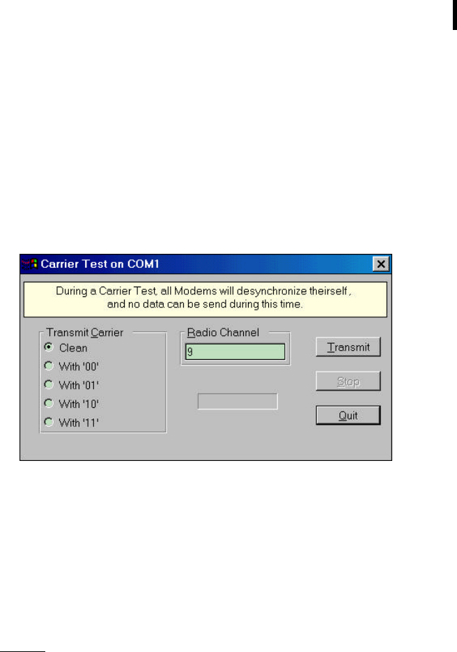
Carrier Transmission Tests can also be simply realized with the WinB900 Software.
The "Carrier Test" option of the "Advanced Configuration" Menu allows to test
Carrier Transmission from a radio module.
When this option is selected, the software display the following window:
• "Carrier Transmission" Selection
Through this window, it is possible to transmit several types of carrier to check
the power and the signal modulation. Here are the following Carrier's choice:
• Pure
• Modulated at ‘00’
• Modulated at ‘01’
• Modulated at ‘10’
• Modulated at ‘11’
Remark:
If a transmission is in progress and you want to change the carrier type, it is
imperative to stop the transmission before selecting another carrier,
otherwise your change will not take effect
• "Radio Channel" Field
This Field available for input specifies the radio channel where the selected
carrier will be transmitted from.
36
• "Transmission" Button
This button allows to initiate the selected carrier transmission based on the
chosen channel. When this button is selected, a red rectangle appears indicating
that the modem is transmitting.
• "Stop" Button
This button stops transmitting the selected carrier.
• "Quit" Button
This button returns to the Main Window.
37
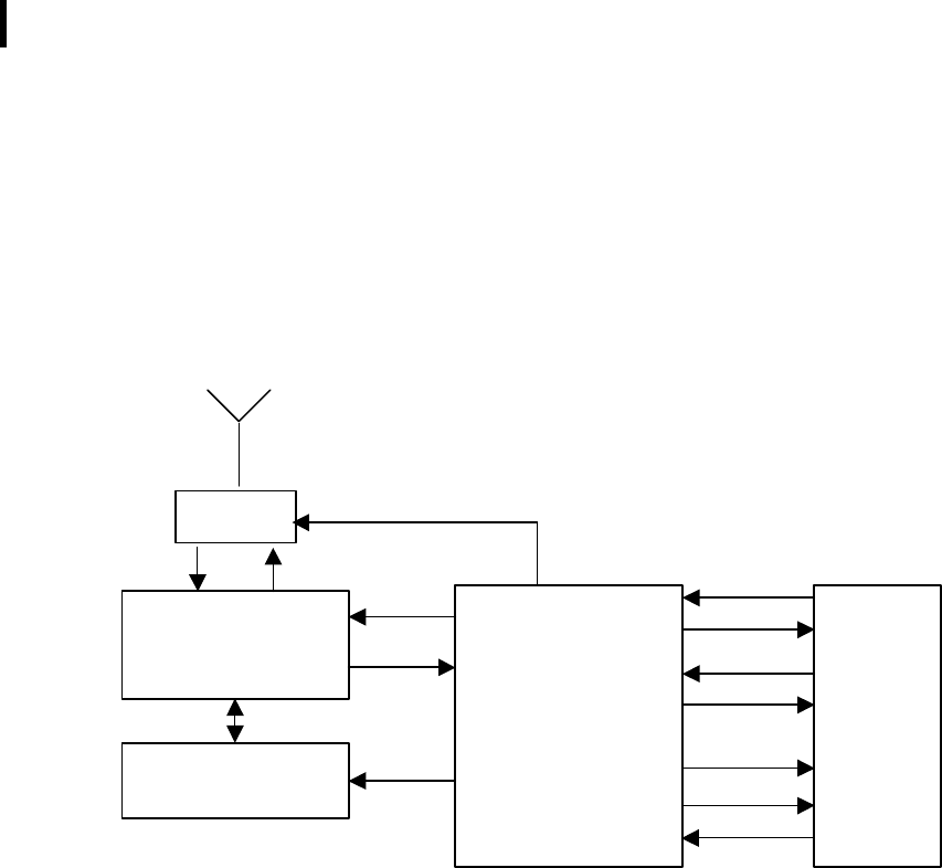
Appendix 1: Schematic Diagram
902 MHz
Transmitter/ Receiver
RF Switch
PLL
MicroController
+
Flash Memory
Interface
RxD
TxD
CTS
RTS
Ack_Tx
Lock
Stand-By
38
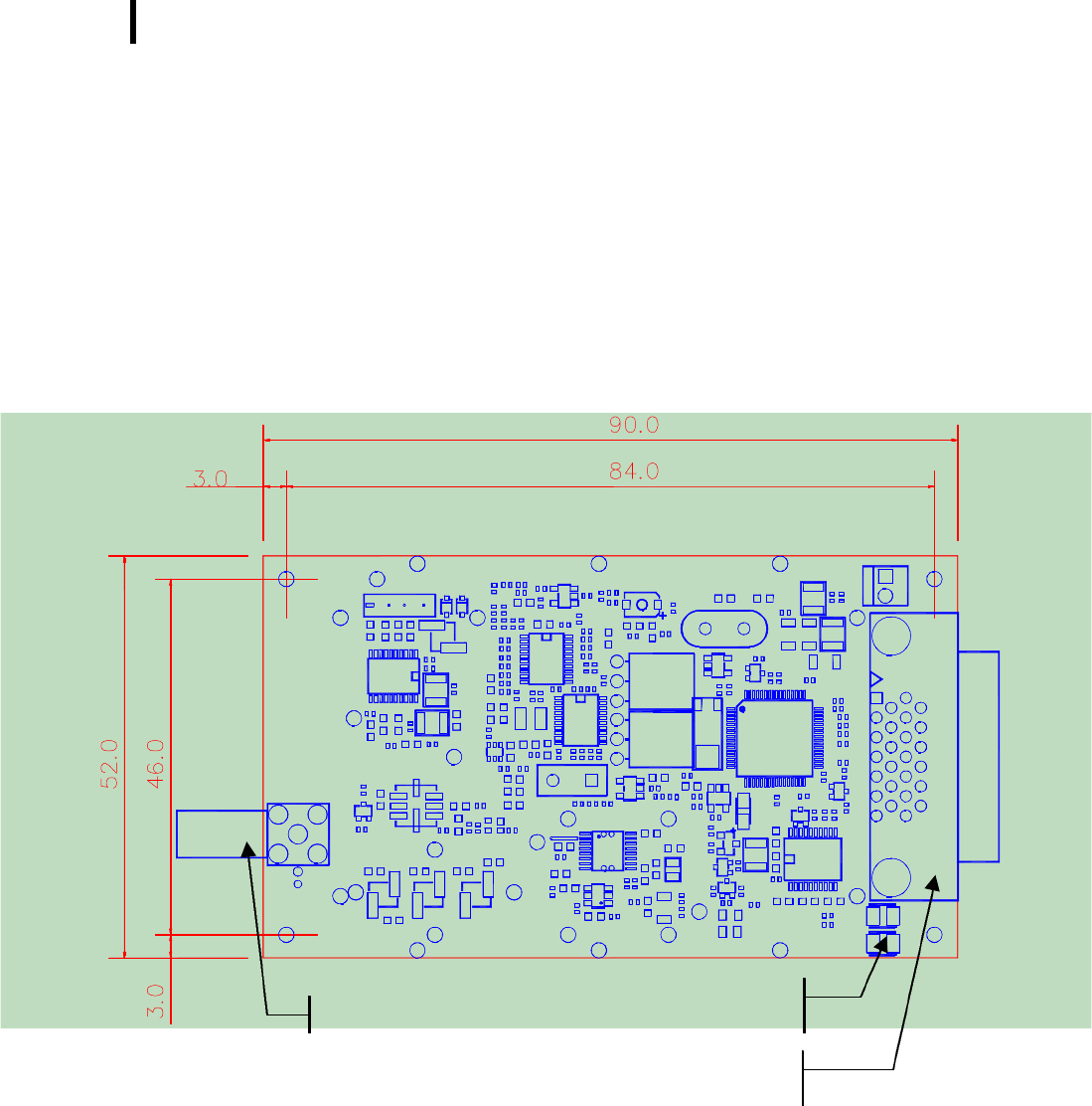
Appendix 2: Mechanical Drawings
Drawing of the B900SS-500 Card
N.B. : dimensions are in millimeters
Serial and supply
power connector
Antenna connector
Red and Green Led for
function indicat
or

39
Interface Signals
The Modem will communicate with the host through an interface with the following
signals:
Bus Pin Interface
Function Signal
direction µC Level of
Signal (1) µC Function
1 & 2 VDD - 3,6V 3,6 volts power for digital & radio ("low noisy").
3 RxD I TTL RxD UART : Serial Data Reception
4 TxD O TTL TxD UART : Serial Data Emission
5 RTS I TTL RT S: Request To Send.
6 CTS O TTL CTS : Clear To Send (INACTIVE).
7 Ack_Tx O TTL Radio Transmission Ok.
8 Tx/Rx O TTL Serial Reception or Transmission.
9 Stand-By I TTL Stand-By with Synchronization On/Off.
10 Lock O TTL Network Synchronization Ok.
11 Tck_Flash I TTL Clock using when flashing firmware.
12 RESET I TTL External Reset. Also used during the programming of
the Flash Program.
13 RxD_Flash I TTL Data Reception using when flashing firmware.
14 TxD_Flash I TTL Data Emission using when flashing firmware.
15 I/O1 I/O TTL/Analog Analog Input or Logic Input/Output.
16 RSSI S Analog Analog level of the received radio signal
17 I/O3 I/O TTL/Analog Analog Input or Logic Input/Output.
18 I/O2 I/O TTL/Analog Analog Input or Logic Input/Output.
19 I/O5 I/O TTL/Analog Analog Input or Logic Input/Output.
20 I/O4 I/O TTL/Analog Analog Input or Logic Input/Output.
21 RxD – RS232 I RS-232 RxD UART : Serial Data Reception
22 TxD – RS232 O RS-232 TxD UART : Serial Data Emission
23 RTS – RS232 I RS-232 RTS : Request To Send.
24 CTS – RS232 O RS-232 CTS : Clear To Send (INACTIVE).
25 & 26
GND - 0V Ground
(1): TTL level is a signal between 0 and 3,6V.
NOTE: The connector used is the Delta-Ribbon 26-pin receptable manufactured and
distributed by 3M.

40
Signals Description
LOCK: Only used on the Client/Slave : Indicates that the synchronization with
the Server/Master is valid. Latter indicates if the Server/Master is at radio
range. Active on high.
RESET: Reset hardware of the modem card. Maximum Duration: 200 ms. Active
on low.
ACK_TX: Indicates that the buffer transmission has been executed correctly. This
signal is valid at the end of the transmission of a radio message (Active
RTS Signal) and is kept until RTS returns to inactive. Active (buffer
transmitted) on low.
xx_Flash : Signals for the Flash programming of the Modem from the host. There
are three signals: RxD, TxD and Clock.
When the host wants to read and/or modify the Flash, the modem must
absolutely be in reset by activating the RESET Signal.
CTS : Clear To Send: signal into the Modem. Indicates if the Modem can send
serial data to the User (Active on low) or not (Inactive on high).
N.B. : NOT USED IN EXISTING VERSION.
RTS : Request To Send: signal going out of the Modem. Indicates that the user
can transmit serial data (Active on low) or not (Inactive on high). This
signal switches when the serial reception buffer's filling rate reaches a
programmable threshold (S215) or when the user finished to transmit
serial data (out on Time-Out).
TxD, RxD: Serial link signals in NRZ format. TxD is for the data going out of the
Modem while RxD is for the data coming into the Modem. Le logic '1' is
represented by high.
Tx/Rx : Indicates that the serial link is on reception or emission mode. This signal
can be used with an half-duplex interface (typical a RS-485). Signal
Active (serial on reception mode) on low.
Stand-By : Stand-By with Synchronization : signal into the Modem. Indicates if the
Modem is in Low-Power Mode (1) or in Normal Mode (0).
With this signal, the synchronization always active and the Modem can
wake-up in Dwell-Timer (S206) milliseconds maximum.
I/Ox : Analog Input (12 bits) or Logic Input/Output. Not used in Standard
firmware, these E/S can be used in a specific firmware or in the future
Standard Firmware. Actually used as Logic Input.
41
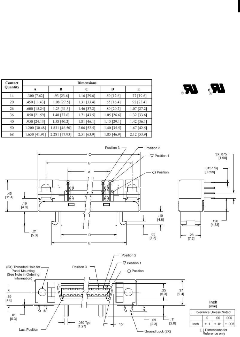
Connector Drawing
The selected connector is the Delta-Ribbon from the 3M. It is a DIP 26-pin angled
connector.

42
Connecting Cable Description
The associated cable should have a mini Delta-Ribbon receptacle with 26 points on
one point and a standard Sub-D 25 points male with a 2 point supply power
connector on the second point. The connection following :
Mini Delta-Ribbon (26 pts) Sub-D 25 points
Power Connect. (2 pts)
Designation I/O N° N° I/O
Designation N° Designation
Power supply 3.6V I 1 & 2 à à 1 (Red) Power 3.6V
Rxd I 3 à 9 O TxD – Hôte
TxD O 4 à 10 I RxD – Hôte
RTS O 5 à 11 I CTS
CTS I 6 à 12 O RTS
Ack_Tx O 7 à 13 I Ack_Tx
Tx/Rx O 8 à 14 I Tx/Rx
Stand-By I 9 à 15 O Stand-By
Lock O 10 à 16 I Lock
Tck_Flash I 11
Reset I 12 à 17 O Reset
RxD_Flash I 13
TxD_Flash O 14
I/O 1 I/O 15 à 21 I/O I/O 1
RSSI (Analogique) S 16 à 18 I RSSI (Analog.)
I/O3 I/O 17 à 23 I/O I/O3
I/O2 I/O 18 à 22 I/O I/O2
I/O 5 I/O 19 à 25 I/O I/O 5
I/O 4 I/O 20 à 24 I/O I/O 4
RxD (RS232) I 21 à 2 O TxD – PC
TxD (RS232) O 22 à 3 I RxD – PC
RTS (RS232) O 23 à 5 I CTS – PC
CTS (RS232) I 24 à 4 O RTS – PC
GND I 25 & 26 à 7 I GND à 2 (Black) GND
43
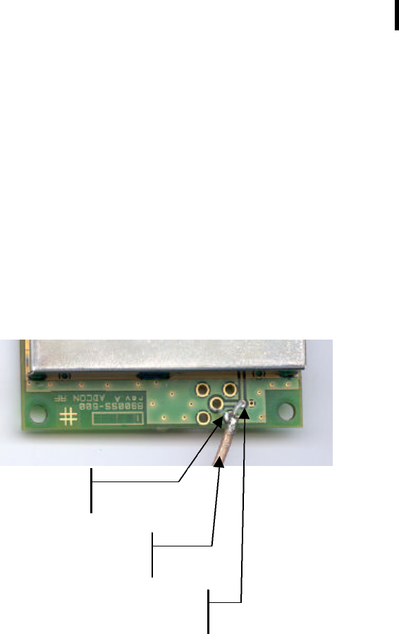
Appendix 3: Antenna Connection
Here is an example of the coaxial cable connection of the 900MHz antenna provided
with the B900SS-500. The hot and cold point can be easily be seen before and after
soldering cable.
"Cold" point where to connect the
breading of the cable (ground)
"Hot" point where to
connect the cable core
Coaxial cable connected
to the anten
na
44
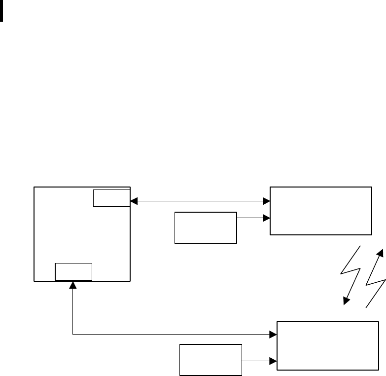
Appendix 4: Connexion for WinB900
Here is how to make the connections to the B900SS-500 in order to operate them
with the WinB900 Software:
B900SS-500 No. 1
(Server or Master)
Windows 95/98
PC and two Serial
Ports
B900SS-500 No. 2
(Client or Slave)
COM1
COM2
Power Supply
Power Supply
45
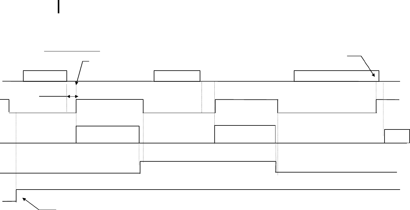
Appendix 5: Timing Diagrams
The user sends data
TxD
RTS
Radio
Ack_Tx
Lock
Serial Data
Radio Transmission
Result : Error
TimeOut
Serial Data
Radio Transmission
Result : OK
Serial Data
Radio
...
Stop on CTS,
Length
≥
S215
Stop on TimeOut
Length<S215
If Slave, Master/Slave synchronization just
ended correctly.
Active
active
inactive
inactive
46
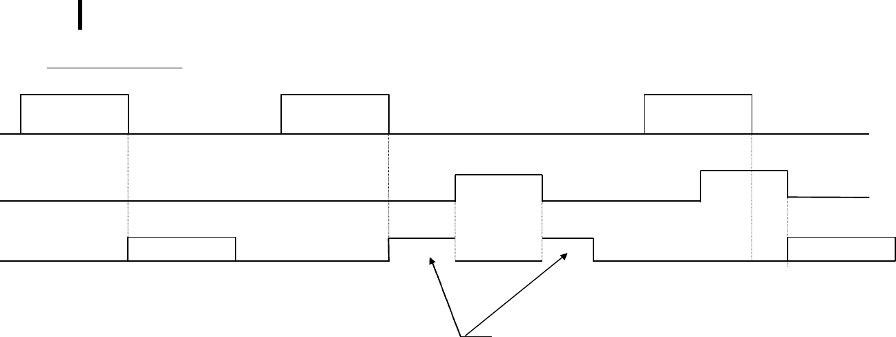
The user Receives data
Radio
CTS
RxD
The CTS signal indicates that the user reception buffer is full. Therefore, the modem does not send data on the serial link
during that time. However, the basic radio operation (synchronization, signal lock, etc.) and the data transmission on the
radio (with data reception on the serial link) continues to operate normally. On the other hand, if another modem sends a
data frame on the radio, this radio frame is not handled (and then not acknowledged). The Transmitter Modem considers
this radio frame as lost and indicates it to the user. (Ack_Tx signal).
It would be better to avoid making the CTS inactive as much as possible.
N.B. : CTS SIGNAL NOT USED IN ACTUAL VERSION.
Data Reception
Serial Data
Data Reception
Serial Data cut in two.
Data Reception
Serial Data
inactive
active

47
Appendix 6: Description of the registers
This section shows a list of all the registers that configure the modems with a software
such as HyperTerminal for Windows.
The B900SS-500 modem will offer several facilities of possible settings.
Each parameter will be in a register and will have a default value that can be changed
in sending the command 'ATSxxx=yy' (Hayes command). Also, the parameter value
will be read when sending the command 'ATSxxx?'.
These parameters are stored in the Eeprom memory and will be available as soon as
powered up.
NOTE: Access Type: 'R' Read and/or 'W' Write.
Access
Type Register Name Description
Frequency Jump
R/W S200 N°. of Used Frequency
Table Between 0 and 8. When Table 0 is selected, the channels remain
the same and stay on the selected channel in S201 (used only for
the tests).
Default: 1.
R/W S201 First Frequency reserved for
the synchronization. Between 0 and 49. Has to be different from S202,S203 and S204.
Default: 0.
R/W S202 Second Frequency reserved
for the synchronization. Between 0 and 49. Has to be different from S201, S203 and S204.
Default: 15.
R/W S203 Third Frequency reserved
for the synchronization. Between 0 and 49. Has to be different from S201, S202 et S204.
Default: 30.
R/W S204 Fourth Frequency reserved
for the synchronization. Between 0 and 49. Has to be different from S201, S202 et S203.
Default: 45.
R/W S205 Auto-Acquisition On Indicate if Acquisition Mode is necessary for build a Point-to-Point
or a Network communication. If not, users MUST write and verify
ALL network parameters (S250 to S254).
'0' : Auto-Acquisition Off.
'1' : Auto-Acquisition On.
Default: 1.
R S206 Dwell Timer Length Calculated based on the Buffer Size (S215) AND Client Count
(S253). Given in milliseconds.
Default: 115 ms (130 Bytes/1 client).

48
Access
Type Register Name Description
Serial Link
R/W S210 Speed.
Indicates the speed on the Serial Connection
'2': 2400 Baud.
'3': 4800 Baud.
'4': 9600 Baud.
'5': 19200 Baud (Default).
'6': 38400 Baud
R/W S211 Data Bits Serial Link Data Bits.
'7': 7 bits.
'8': 8 bits (Default).
R/W S212 Parity Indicates Serial Link Parity Type:
'1': None (Default).
'2': Even.
'3': Odd.
R/W S213 Stop Bits Indicates Serial Link numbers of Stop Bits :
'1': One Stop Bit (Default).
'2': Two Stop Bit.
R/W S214 Serial Link Time Out Time_Out in milliseconds. Between 2 and 100 milliseconds.
Default: 5 ms.
R/W S215 Buffer Size Indicates the maximum size of the frames that will be given to
the Modem. When this size is reached, the modem resets the
RTS signal, and if another byte is received, it is loss.
It has to be between 30 Bytes and 130 Bytes (physical size).
Default: 130 Bytes.

49
Access
Type Register Name Description
Operation
R/W S220 Server or Client Mode Indicates the operation of the Modem. When the Modem is
configured as Master (or Server), the S252 Register switches
automatically to 0xFF, while it switches to 0 when configured
as Slave (or Client).
'0' : Server (Network),
'1' : Client (Network),
'2' : Master,
'3': Slave (Default).
R/W S221 Recovery Count Maximum recovery count in case of problems (Non-Ack
response to a message).
If this Register is at 0, the frames are not checked and
considered as still good (used for the tests).
Default: 2.
Personal Network Control
R/W S250
Number of Personal Network
(or Network)
This register gives the Personal Network (Network) number
on 2 Bytes. Only the two members of a same Personal
Network can communicate with each other. Between 0 and
65535, it is at 0 when the modem is reset.
NOTE: When this register is reset to 0, Registers S252, S253
and S254 are also automatically reset to 0.
Default: 0.
R or
R/W (2)
S252 Modem Number Gives the Modem a unique number for a given Personal
Network.
Number on one Byte is 0 when the Modem is
reset, 1 if it is a Slave, between 1 and 16 if it is a Client and
255 if it is the Master.
Default: 0.
R or
R/W (2)
S253 Clients Count Gives the Client count of a Master Modem or a Server.
Between 0 and 1 if Master, 0 and 16 if Server.
Default: 0.
R/W S254 Client Addition Gives the number of a Client to be added in the already set
up network. This number should be between 1 and S253.
Only used on a Network Server.
Default: 0.
(2) : This registers are in R/W mode if Auto-Acquisition is deselected (S205=0), and
only in Read mode if Auto-Acquisition is selected (S205=1).

50
Appendix 7: Document Revisions History
No. of
Revision Date Author Subject
0.1 05/04/01 GS Creation.
0.2 19/06/01 GS Modification about WinB900SS

51
Appendix 8: B900SS-500 Firmware Version
History
Version 0.01ß : First version of the B900SS-500 firmware. Full compatible with the firmware V0.31a of the
B900SS-20.
Version 0.02ß : Evolution of the V0.01ß. Full compatible with the firmware V0.33ß of the B900SS-20, with the
same evolutions.
Version 0. 30ß : Evolution of the V0.02ß. Full compatible with the firmware V0.36ß of the B900SS-20, with the
same evolutions.
Version 0. 40ß : Evolution of the V0.30ß. Modification of all Channels Tables, based on the B900SS FCC
restriction. Normally compatible with the firmware V0.40ß of the B900SS-20.
Version now in Test by FCC.

RF EXPOSURE STATEMENT
Notice in Installation Manual:
FCC Radiation Exposure Statement
This equipment complies with FCC radiation exposure limits set forth for an uncontrolled
environment, when installed as directed. This equipment should be installed and operated
with fix-mounted antennas that are installed with a minimum of 21 centimeters of
separation distance between the antenna and all persons’ body during normal operations.
RF Exposure Calculations:
The following information provides the minimum separation distance for the highest
gain antenna provided with the Adcon Telemetry MQXB900SS-500, as calculated from
FCC OET 65 Appendix B, Table 1B Guidelines for General Population/Uncontrolled
Exposure. This calculation is based on the highest EIRP possible from the system,
considering maximum power and antenna gain, and considering a 0.61 mW/cm^2
uncontrolled exposure limit.
R = (Po*G) / (4*Pi*S)
R = Minimum safe distance from antenna
S = Exposure Limit ( from FCC OET 65, appendix B, Table 1 part B)
= f / 1500
= 915 / 1500
= 0.61 mW/cm^2 at 915MHz
Po = Peak RF energy
= 500 mW
G = antenna gain (numeric)
G(isotropic) = 6dBd + 2.15 = 8.15 dBi
G(numeric) = 10^(G(dBi)/10)
= 6.531
R = (500 * 6.531) / (4 * Pi * 0.61)
R = 20.64 centimeters
Formula derived from
OET BULLETIN 65 (edition 97-01)
Section 2, equation 3