Adcon Telemetry D900SS-20-A User Manual Objective
Adcon Telemetry Inc Objective
UserManual.wiki
>
Adcon Telemetry
>
D900SS 20 A User Manual
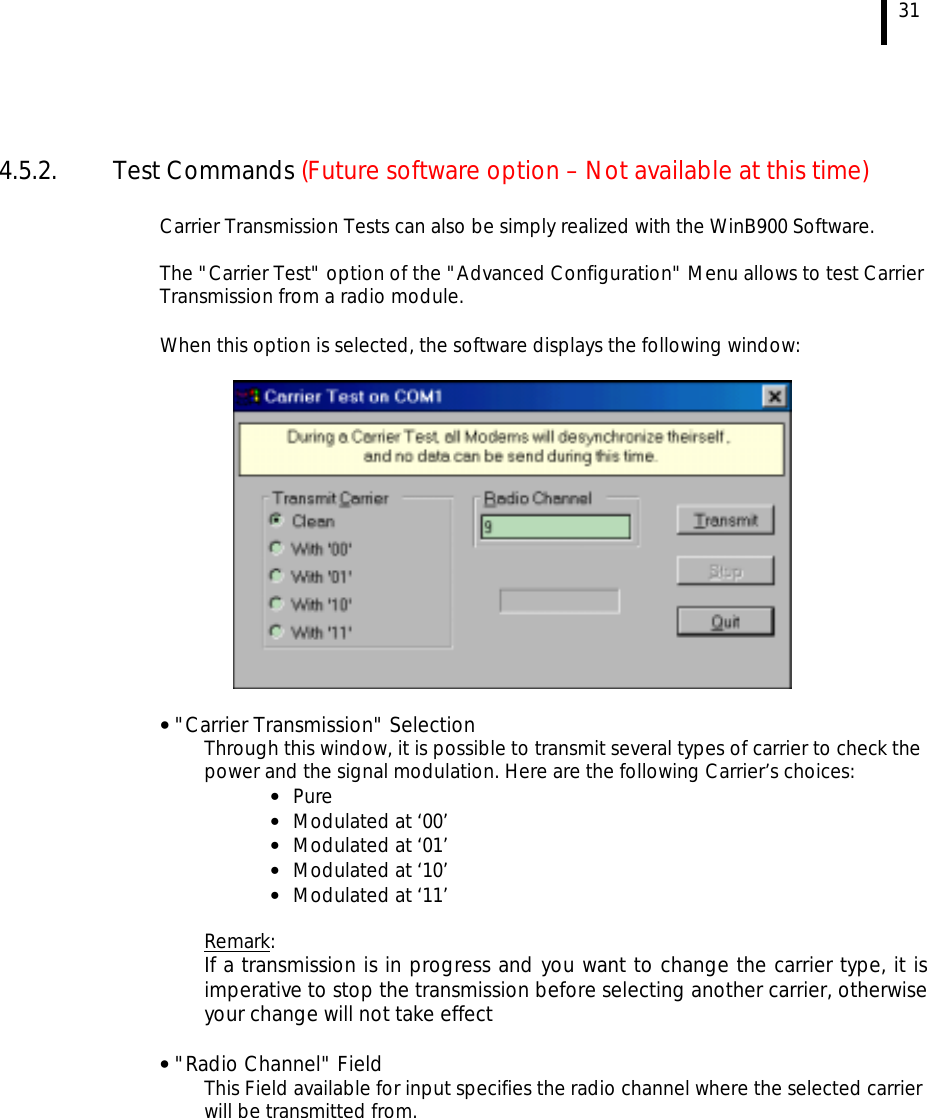
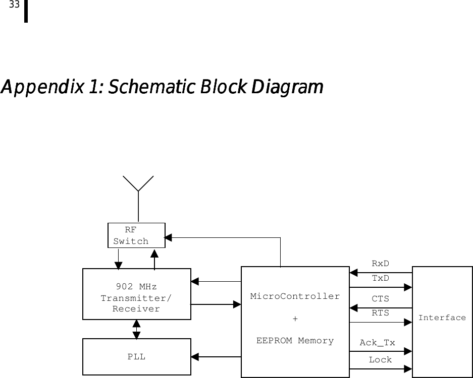
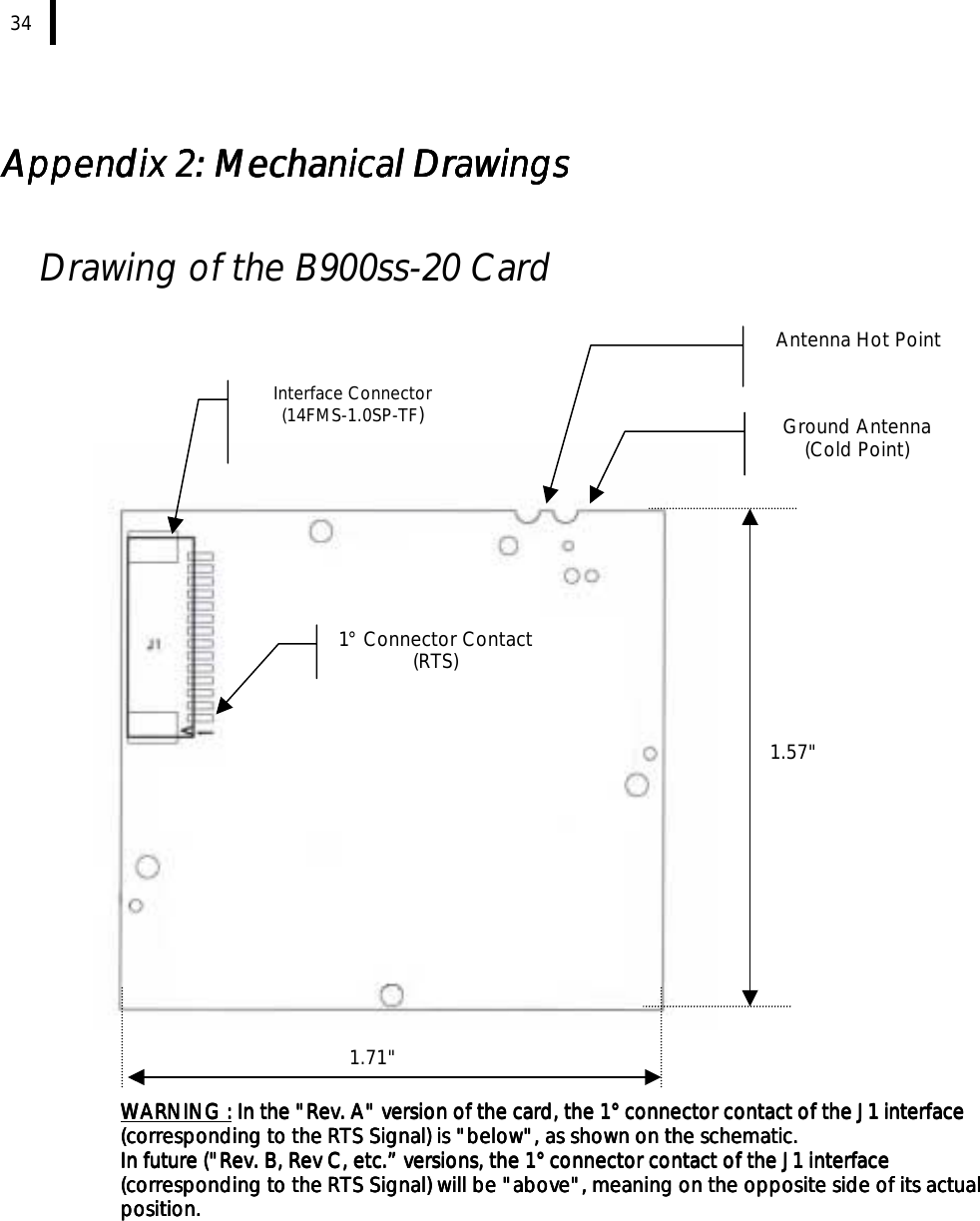
Users Manual
Navigation menu
Upload a User Manual
Namespaces
Wiki Guide
HTML
PDF
Info
Views
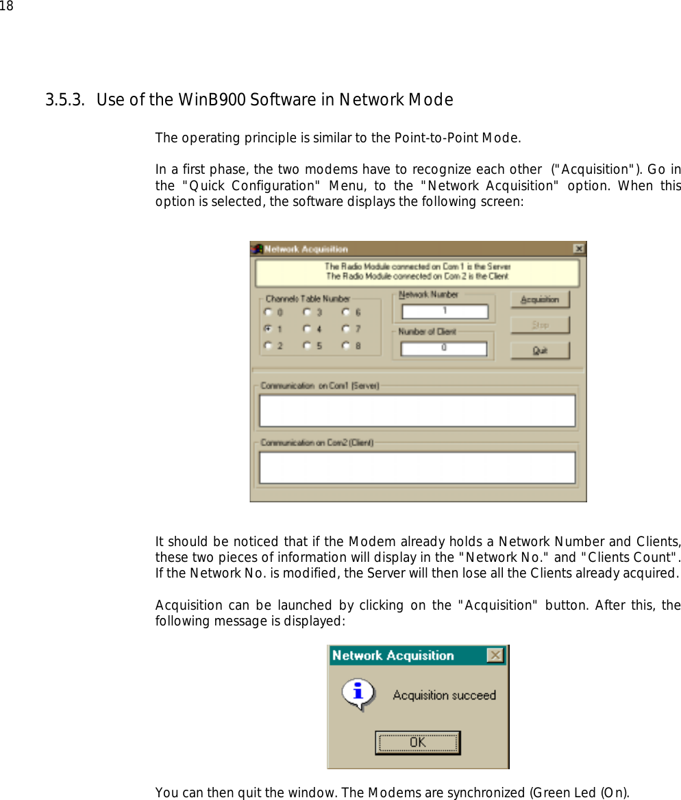
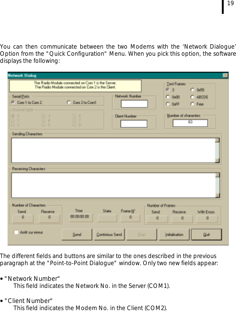
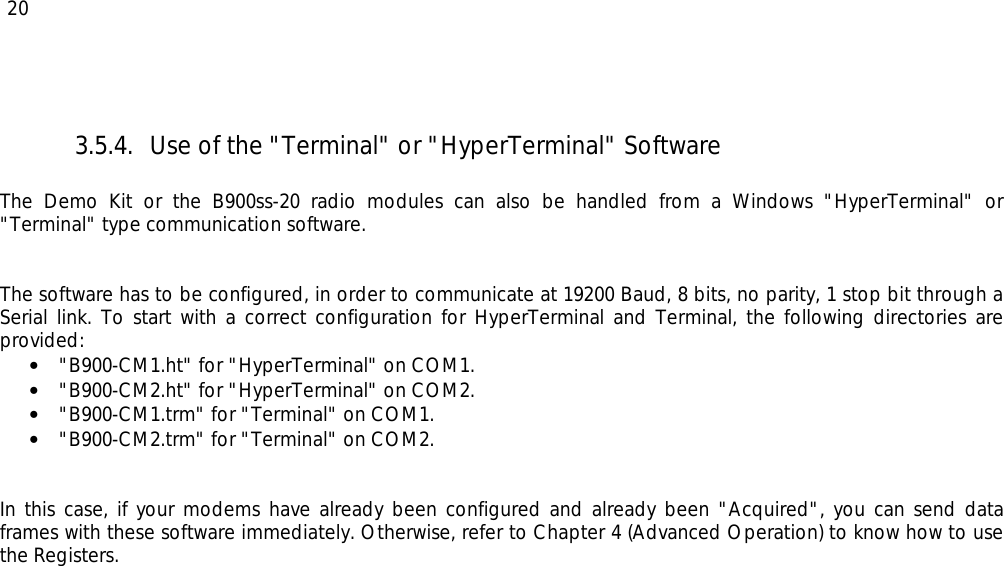
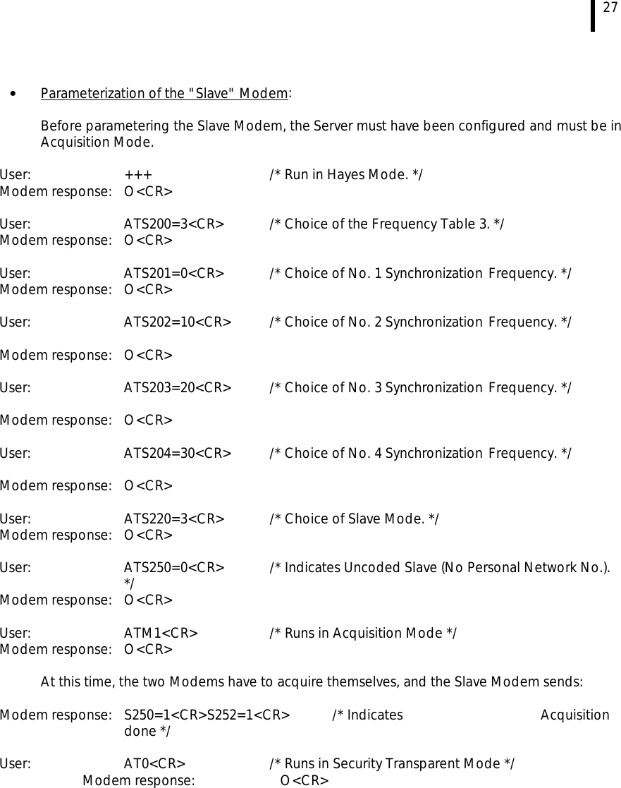
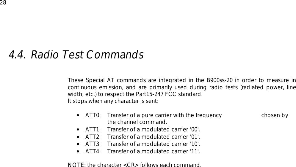
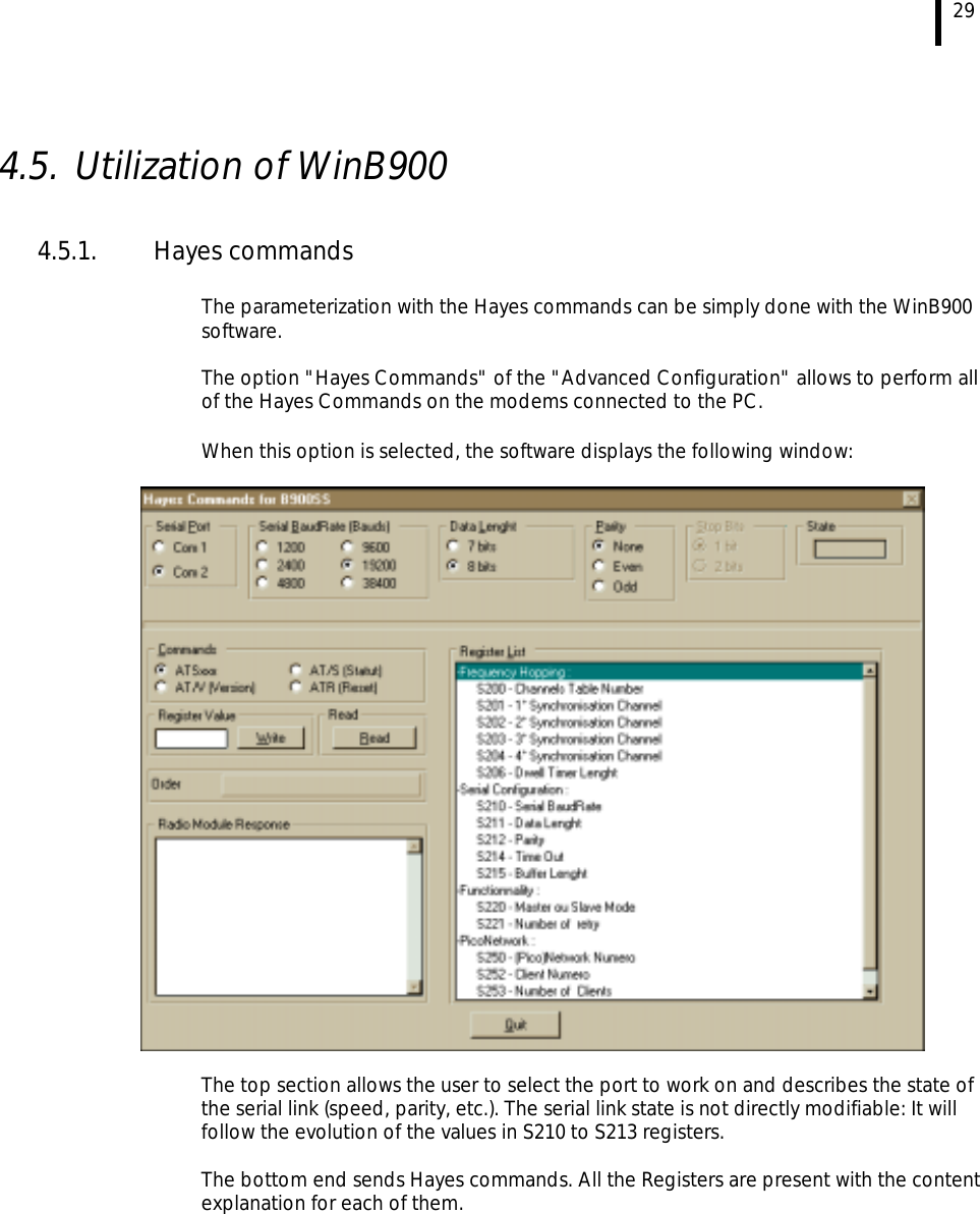
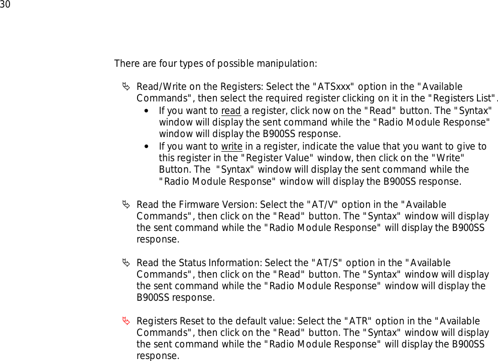
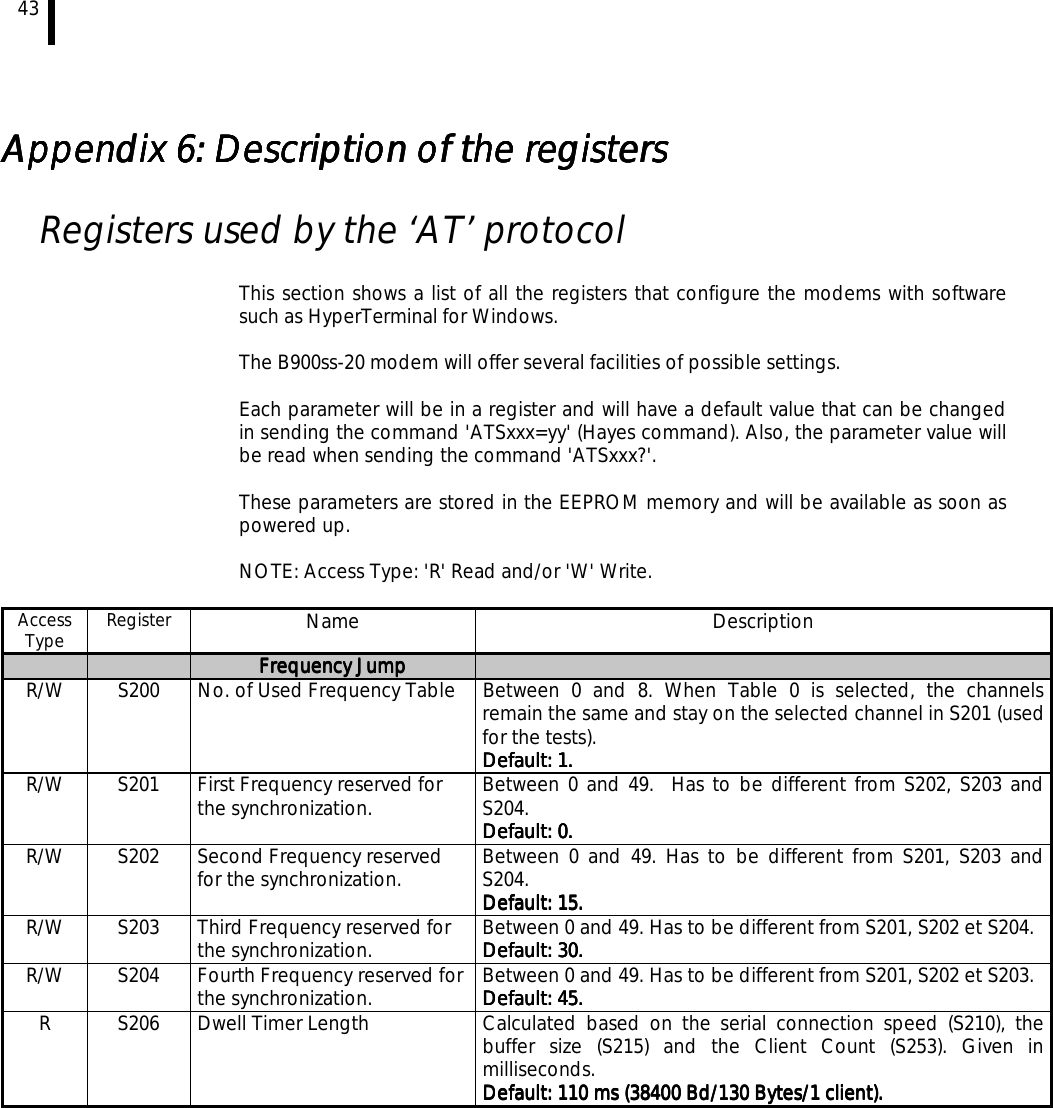
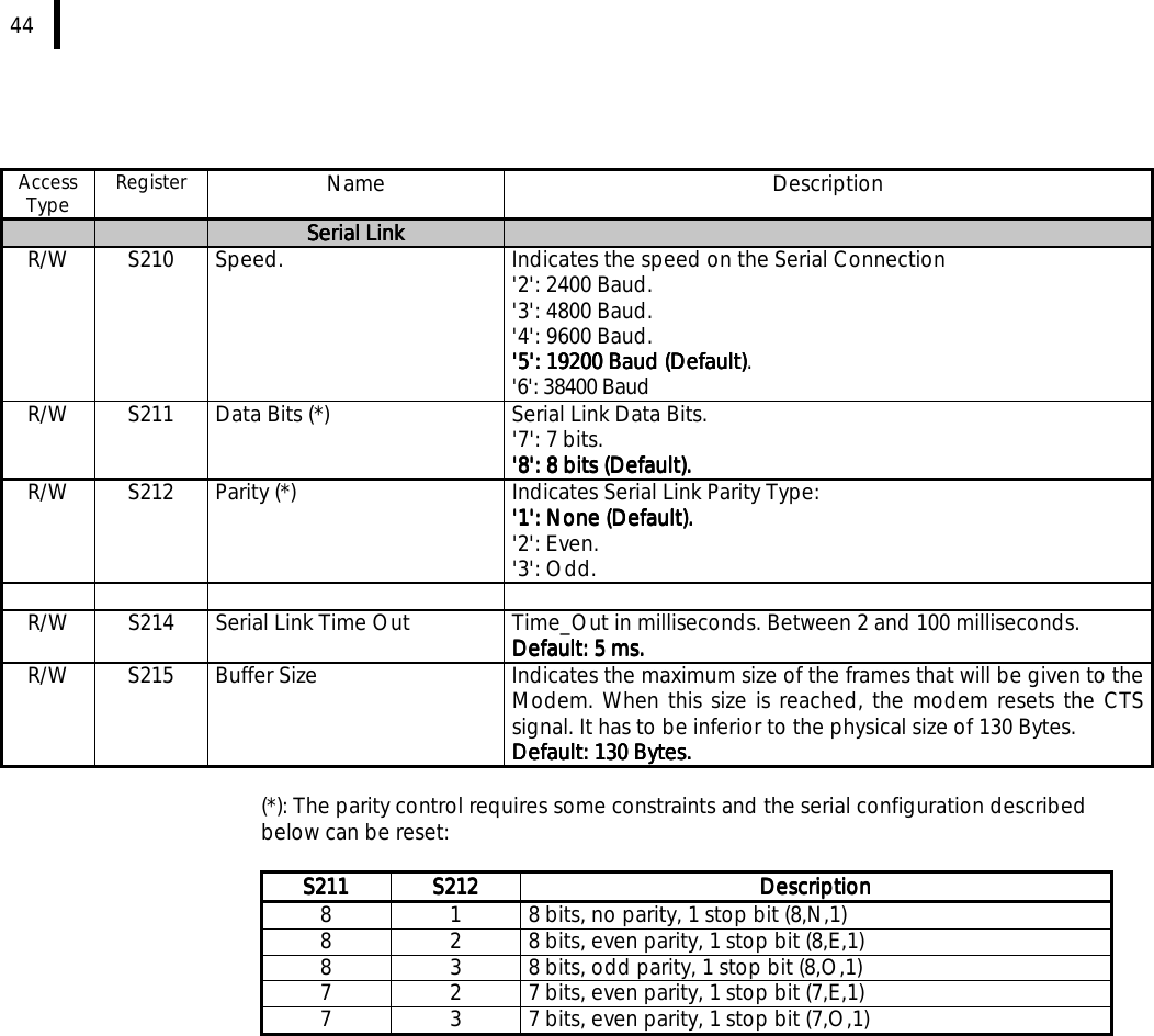
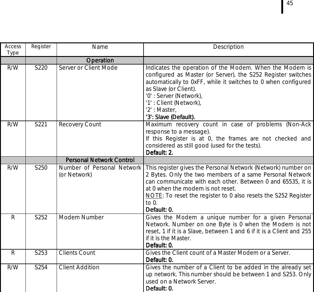
User Manual
Discussion / Help
Navigation