Adcon Telemetry D900SS-20-A User Manual Objective
Adcon Telemetry Inc Objective
Users Manual

Technical Manual
Technical ManualTechnical Manual
Technical Manual
EDITION: 0.
EDITION: 0.EDITION: 0.
EDITION: 0.7
77
7
UPDATED: August 7, 2001
B900ss-20
Radio Modem Card
Spread Spectrum
(FCC Approved
Part 15.247)

2
ADCON AG
Adcon Telemetry, Inc.
1001 Yamato Road
Suite 305
Boca Raton, Florida 33431
Tel: 561-989-5309
Fax: 561-989-5310
Internet Site
http://www.adcon.com
E-mail
info@adcon.com
The information within this document may be modified without notice. No part of this manual can
be duplicated or transferred, electronically or mechanically in any way, without ADCON AG.'s
strict and written consent.

3
INDEX
Chapter 1.
Objective................................
................................................................
................................................................
................................................................
................................................................
................................................................
..............................................
............................
.............. 5
55
5
Chapter 2.
Module introduction ................................
................................................................
................................................................
................................................................
...........................................................
......................................................
........................... 6
66
6
2.1.
Description................................
................................................................
................................................................
................................................................
................................................................
................................................................
................................................................
................................................................
................................ 6
66
6
2.2.
Specifications................................
................................................................
................................................................
................................................................
................................................................
................................................................
............................................................
........................................................
............................ 7
77
7
2.2.1. General.............................................................................................................................................7
2.2.2. Specifications of the B900ss-20 ......................................................................................................7
2.2.3. Schematic.........................................................................................................................................9
2.3.
Available Configuration ................................
................................................................
................................................................
................................................................
................................................................
................................................................
.........................................
..................
......... 10
1010
10
2.3.1. Software Configuration .................................................................................................................10
2.3.2. Hardware Configuration................................................................................................................10
Chapter 3.
Basic Operation................................
................................................................
................................................................
................................................................
................................................................
................................................................
.................................
...11
1111
11
3.1.
General................................
................................................................
................................................................
................................................................
................................................................
................................................................
................................................................
................................................................
....................................
........
.... 11
1111
11
3.2.
"Hayes" Mode................................
................................................................
................................................................
................................................................
................................................................
................................................................
........................................................
................................................
........................ 11
1111
11
3.3.
"Point-to-Point" Mode................................
................................................................
................................................................
................................................................
................................................................
................................................................
...........................................
......................
........... 12
1212
12
3.4.
"Network" Mode................................
................................................................
................................................................
................................................................
................................................................
................................................................
....................................................
........................................
.................... 13
1313
13
3.5.
DemoKit Utilization ................................
................................................................
................................................................
................................................................
................................................................
................................................................
................................................
................................
................ 14
1414
14
3.5.1. Installation and Connection..........................................................................................................14
3.5.2. WinB900 Software Utilization in Point-to-Point Mode ................................................................15
3.5.3. Use of the WinB900 Software in Network Mode.........................................................................18
3.5.4. Use of the "Terminal" or "HyperTerminal" Software .................................................................20
Chapter 4.
Advanced Operation................................
................................................................
................................................................
................................................................
.........................................................
..................................................
......................... 21
2121
21
4.1.
General................................
................................................................
................................................................
................................................................
................................................................
................................................................
................................................................
................................................................
....................................
........
.... 21
2121
21
4.2.
"Hayes" Protocol Commands................................
................................................................
................................................................
................................................................
...............................................................
..............................................................
............................... 22
2222
22
4.2.1. General...........................................................................................................................................22
4.2.2. Description of the standard commands.......................................................................................23
4.2.3. Registers Description ....................................................................................................................24
4.3.
Utilization Example................................
................................................................
................................................................
................................................................
................................................................
................................................................
.................................................
..................................
................. 25
2525
25
4.3.1. Acquisition of two Point-to-Point Modems..................................................................................25
4.4.
Radio Test Commands................................
................................................................
................................................................
................................................................
................................................................
................................................................
...........................................
......................
........... 28
2828
28

4
4.5.
Utilization of WinB900................................
................................................................
................................................................
................................................................
................................................................
................................................................
............................................
........................
............ 29
2929
29
4.5.1. Hayes commands...........................................................................................................................29
4.5.2. Test Commands.............................................................................................................................31
Appendix 1: Schematic Block Diagram
Appendix 1: Schematic Block DiagramAppendix 1: Schematic Block Diagram
Appendix 1: Schematic Block Diagram ................................
................................................................
................................................................
................................................................
....................................................
........................................
....................33
3333
33
Appendix 2: Mechanical Drawings
Appendix 2: Mechanical DrawingsAppendix 2: Mechanical Drawings
Appendix 2: Mechanical Drawings................................
................................................................
................................................................
................................................................
............................................................
........................................................
............................34
3434
34
Drawing of the B900ss-20 Card ................................
................................................................
................................................................
................................................................
................................................................
................................................................
..........................................
....................
.......... 34
3434
34
Interface Signals................................
................................................................
................................................................
................................................................
................................................................
................................................................
................................................................
................................................................
...................................
......
... 35
3535
35
Connector Drawing ................................
................................................................
................................................................
................................................................
................................................................
................................................................
.............................................................
..........................................................
............................. 37
3737
37
Connecting Cable Drawing................................
................................................................
................................................................
................................................................
................................................................
................................................................
.................................................
..................................
................. 37
3737
37
Appendix 3: Antenna Connection
Appendix 3: Antenna ConnectionAppendix 3: Antenna Connection
Appendix 3: Antenna Connection ................................
................................................................
................................................................
................................................................
............................................................
........................................................
............................38
3838
38
Appendix 4: D900SS
Appendix 4: D900SSAppendix 4: D900SS
Appendix 4: D900SS-
--
-20 DemoKit
20 DemoKit20 DemoKit
20 DemoKit ................................
................................................................
................................................................
................................................................
................................................................
................................................................
.................................
...39
3939
39
Composition................................
................................................................
................................................................
................................................................
................................................................
................................................................
................................................................
................................................................
.........................................
..................
......... 39
3939
39
Connections................................
................................................................
................................................................
................................................................
................................................................
................................................................
................................................................
................................................................
.........................................
..................
......... 40
4040
40
Appendix 5: Timing Diagrams
Appendix 5: Timing DiagramsAppendix 5: Timing Diagrams
Appendix 5: Timing Diagrams................................
................................................................
................................................................
................................................................
................................................................
................................................................
...................................
......
...41
4141
41
Appendix 6: Description of the registers
Appendix 6: Description of the registersAppendix 6: Description of the registers
Appendix 6: Description of the registers ................................
................................................................
................................................................
................................................................
.................................................
..................................
.................43
4343
43
Registers used by the ‘AT’ protocol................................
................................................................
................................................................
................................................................
................................................................
................................................................
...................................
......
... 43
4343
43
Appendix 7: Revisions History
Appendix 7: Revisions HistoryAppendix 7: Revisions History
Appendix 7: Revisions History................................
................................................................
................................................................
................................................................
................................................................
................................................................
...................................
......
...46
4646
46

5
Chapter 1. Objective
The objective of this document is to present the features and the application of the
B900ss-20 radio module.
The operation of this module is divided into two chapters:
• The ‘Basic Operation’ chapter describes the Module operating modes and allows
the user to learn the WinB900 Software in walking through it.
• The ‘Advanced Operation’ is especially for users that want to program the module
directly. It presents all the available commands.
FCC Compliance and Warning
FCC Compliance and WarningFCC Compliance and Warning
FCC Compliance and Warning
Thank you for choosing Adcon Telemetry's B900ss
Thank you for choosing Adcon Telemetry's B900ssThank you for choosing Adcon Telemetry's B900ss
Thank you for choosing Adcon Telemetry's B900ss-
--
-20 Smart Spread Spectrum RF
20 Smart Spread Spectrum RF 20 Smart Spread Spectrum RF
20 Smart Spread Spectrum RF
Module, which has been tested and found to comply with the limits for a Class B digita
Module, which has been tested and found to comply with the limits for a Class B digitaModule, which has been tested and found to comply with the limits for a Class B digita
Module, which has been tested and found to comply with the limits for a Class B digital
l l
l
device, pursuant to Part 15 of the FCC Rules.
device, pursuant to Part 15 of the FCC Rules.device, pursuant to Part 15 of the FCC Rules.
device, pursuant to Part 15 of the FCC Rules.
In accordance with FCC rules and regulations, Part 15, this is to advise you that if the
In accordance with FCC rules and regulations, Part 15, this is to advise you that if the In accordance with FCC rules and regulations, Part 15, this is to advise you that if the
In accordance with FCC rules and regulations, Part 15, this is to advise you that if the
FCC ID number of the Smart Spread Spectrum is not visible when installed inside your
FCC ID number of the Smart Spread Spectrum is not visible when installed inside your FCC ID number of the Smart Spread Spectrum is not visible when installed inside your
FCC ID number of the Smart Spread Spectrum is not visible when installed inside your
device, then the outside of your
device, then the outside of your device, then the outside of your
device, then the outside of your device into which the module is installed must also
device into which the module is installed must also device into which the module is installed must also
device into which the module is installed must also
display a label referring to the enclosed module. This exterior label can use wording
display a label referring to the enclosed module. This exterior label can use wording display a label referring to the enclosed module. This exterior label can use wording
display a label referring to the enclosed module. This exterior label can use wording
such as the following: "Contains FCC ID: MQXB900ss
such as the following: "Contains FCC ID: MQXB900sssuch as the following: "Contains FCC ID: MQXB900ss
such as the following: "Contains FCC ID: MQXB900ss-
--
-20." Any similar wording that
20." Any similar wording that 20." Any similar wording that
20." Any similar wording that
expresses the same meaning may be use
expresses the same meaning may be useexpresses the same meaning may be use
expresses the same meaning may be used.
d. d.
d.
In addition the following statement should also be included on an exterior label (or in
In addition the following statement should also be included on an exterior label (or in In addition the following statement should also be included on an exterior label (or in
In addition the following statement should also be included on an exterior label (or in
your documentation, if the unit is too small to accommodate the label) "
your documentation, if the unit is too small to accommodate the label) "your documentation, if the unit is too small to accommodate the label) "
your documentation, if the unit is too small to accommodate the label) "This device
This device This device
This device
complies with Part 15 of the FCC Rules. Operation is subject to the following t
complies with Part 15 of the FCC Rules. Operation is subject to the following tcomplies with Part 15 of the FCC Rules. Operation is subject to the following t
complies with Part 15 of the FCC Rules. Operation is subject to the following two
wo wo
wo
conditions: (1) this device may not cause harmful interference, and (2) this device must
conditions: (1) this device may not cause harmful interference, and (2) this device must conditions: (1) this device may not cause harmful interference, and (2) this device must
conditions: (1) this device may not cause harmful interference, and (2) this device must
accept any interference that may cause undesired operation.
accept any interference that may cause undesired operation.accept any interference that may cause undesired operation.
accept any interference that may cause undesired operation. "
" "
"
Adcon’s Smart Spread Spectrum Modules
Adcon’s Smart Spread Spectrum ModulesAdcon’s Smart Spread Spectrum Modules
Adcon’s Smart Spread Spectrum Modules
are designed as component devices, which
are designed as component devices, which are designed as component devices, which
are designed as component devices, which
require external compo
require external comporequire external compo
require external components to function. The B900ss
nents to function. The B900ssnents to function. The B900ss
nents to function. The B900ss-
--
-20 modules are intended to allow
20 modules are intended to allow 20 modules are intended to allow
20 modules are intended to allow
for full Part 15 compliance and are approved by the FCC. The purchaser understands
for full Part 15 compliance and are approved by the FCC. The purchaser understands for full Part 15 compliance and are approved by the FCC. The purchaser understands
for full Part 15 compliance and are approved by the FCC. The purchaser understands
that further approvals may be required prior to the sale or operation of the device, and
that further approvals may be required prior to the sale or operation of the device, and that further approvals may be required prior to the sale or operation of the device, and
that further approvals may be required prior to the sale or operation of the device, and
agrees to utilize the
agrees to utilize theagrees to utilize the
agrees to utilize the component in keeping with all laws governing its operation in the
component in keeping with all laws governing its operation in the component in keeping with all laws governing its operation in the
component in keeping with all laws governing its operation in the
country of operation."
country of operation."country of operation."
country of operation."
In order to comply with the FCC rules and regulations, the B900ss
In order to comply with the FCC rules and regulations, the B900ssIn order to comply with the FCC rules and regulations, the B900ss
In order to comply with the FCC rules and regulations, the B900ss-
--
-20 RF Module may
20 RF Module may 20 RF Module may
20 RF Module may
only be used with approved antennas that have been tested with this radio. At this
only be used with approved antennas that have been tested with this radio. At thisonly be used with approved antennas that have been tested with this radio. At this
only be used with approved antennas that have been tested with this radio. At this
writing the only approved antenna is the quarter
writing the only approved antenna is the quarterwriting the only approved antenna is the quarter
writing the only approved antenna is the quarter-
--
-wave rubber duck antenna by MAT. If
wave rubber duck antenna by MAT. If wave rubber duck antenna by MAT. If
wave rubber duck antenna by MAT. If
the OEM integrates the MQXB900ss
the OEM integrates the MQXB900ssthe OEM integrates the MQXB900ss
the OEM integrates the MQXB900ss-
--
-20 into their final product, where the product
20 into their final product, where the product 20 into their final product, where the product
20 into their final product, where the product
utilizes a non
utilizes a nonutilizes a non
utilizes a non-
--
-approved antenna, the OEM is responsible for obtaining a separate
approved antenna, the OEM is responsible for obtaining a separate approved antenna, the OEM is responsible for obtaining a separate
approved antenna, the OEM is responsible for obtaining a separate
authoriza
authorizaauthoriza
authorization on the final product.
tion on the final product.tion on the final product.
tion on the final product.

6
This wireless transmitter contains a low power transmitter.
This wireless transmitter contains a low power transmitter.This wireless transmitter contains a low power transmitter.
This wireless transmitter contains a low power transmitter. When in transmit it sen
When in transmit it sen When in transmit it sen
When in transmit it sends
ds ds
ds
out radio frequ
out radio frequout radio frequ
out radio frequency (RF) energy.
ency (RF) energy. ency (RF) energy.
ency (RF) energy. In August 1996 the Federal Communications
In August 1996 the Federal Communications In August 1996 the Federal Communications
In August 1996 the Federal Communications
Commi
CommiCommi
Commission
ssionssion
ssion (FCC) adopted RF
(FCC) adopted RF (FCC) adopted RF
(FCC) adopted RF exposure safety guidelines.
exposure safety guidelines. exposure safety guidelines.
exposure safety guidelines. To maintain compliance
To maintain compliance To maintain compliance
To maintain compliance
with the
with the with the
with the FCC
FCCFCC
FCC’
’’’s
ss
s RF safety exposure guideli
RF safety exposure guideli RF safety exposure guideli
RF safety exposure guideline
nene
nes
ss
s it is recommended that you remain 2
it is recommended that you remain 2 it is recommended that you remain 2
it is recommended that you remain 2
inches (5 centimeters)
inches (5 centimeters) inches (5 centimeters)
inches (5 centimeters) away from the antenna
away from the antenna away from the antenna
away from the antenna while the unit is transmitting.
while the unit is transmitting. while the unit is transmitting.
while the unit is transmitting. The
The The
The
D900ss
D900ssD900ss
D900ss-
--
-20
2020
20
Demo Kit
Demo Kit Demo Kit
Demo Kit comes supplied with a permanently
comes supplied with a permanently comes supplied with a permanently
comes supplied with a permanently attached antenna.
attached antenna. attached antenna.
attached antenna.
Modifications or attachments
Modifications or attachments Modifications or attachments
Modifications or attachments could damage the transmitter, alter the RF exposure
could damage the transmitter, alter the RF exposurecould damage the transmitter, alter the RF exposure
could damage the transmitter, alter the RF exposure, and
, and , and
, and
may violate FCC
may violate FCC may violate FCC
may violate FCC regulations.
regulations.regulations.
regulations.
Chapter 2. Module introduction
2.1. Description
The B900ss-20 is an FM radio transceiver with frequency hopping using an F.S.K
modulation. The receiver is of a super beat oscillator type with heterodyning. It
operates on the 902-928 MHz band and, therefore, is within U.S. FCC part 15.247
standard.
Using the frequency synthesis, it has a maximum of 50 channels spaced by 150 kHz and
can communicate with equipment via a serial interface with RS-232 standard and TTL
levels.
The serial link is completely programmable from 2400 up to 38400 Baud. The radio rate
is established at 40 KBits/s.
The B900ss-20 uses the most recent technology of flash memory micro controller, which
allows the user to update or to load new features through the serial link.
Many parameters are programmable through the serial link and the default
configuration is memorized in an EEPROM (ROM).
At each activation, the radio modem component is programmed with its configuration
parameters (Channel, Speed, Protocol, etc.).
The default data are: RS-232 connection at 19,200 Baud, 8 bits, 1 stop bit, no parity,
Frequency Table 1, slave modem.
All these parameters are accessible and modifiable with HAYES or AT commands.

7
2.2. Specifications
2.2.1. General
The B900ss-20 is a radio card component that receives and transmits data according to
a frequency table selected by the user.
2.2.2. Specifications of the B900ss-20
Dimensions
Weight: <2 ozs. (< 50 grams)
Dimensions: 1.57" x 1.69" x .29" (without antenna).
Connectors: 1 14FMS-1.0SP-TF 14 pin connector from JST.
Electronics
• Radio part
Frequency: 902 to 928 MHz (FCC part 15-247).
Number of channels: 50, channel 0 to 49.
Channel selection: Frequency hopping, according to a random
table of 50 channels. 8 tables are stored in
EEPROM memory.
Radio rate: 40KBits/s.
Modulation/Demodulation: FSK (Frequency Shift Keying).
Bit encoding: Quad Frequential encoding.
RF sensitivity: -90 dBm (± 2 dB) at 50 Ohms.
RF power: +13 dBm (20 mW) (± 2 dB) over 50 Ohms.
Error rate: 10-4 to -88 dBm.
Saturation: Two modules communicate at 0 dBm.
Operating Temp.: Standard Operation: +32°F to +122°F.
(0º to +50º Centigrade)
Storage Temp.: -40°F to +176°F (-40ºC to +80º C)
Relative humidity: from 20% to 90% RH (without condensation).

8
• Digital Part
Processor: FLASH Atmel Micro controller
Programming: Upload and download with a PC through the RS232
serial link and a specific interface (Demo Kit D900).
Program Mem.: 8 Ko of FLASH
Data Memory: 512 bytes of RAM for stack and data
EEPROM Memory: 512 bytes for the HAYES parameters (registers S).
Serial Link: 2400 to 38400 Baud, NRZ format, 5 volts TTL level.
• Power Supply
Supply voltage: 5V monitored (± 5%).
Consumption: Receive Transmit Sleep
<40mA <80mA <5mA
• HAYES Commands:
The user can program all the parameters. A Windows programming software
is supplied "on-line" with documentation support. (See AT commands).
Examples of Hayes commands:
Serial: Serial link rate, parity, bit count, stop bit count, Serial Time-
out, …
Radio: Channels table selection, retry count, …
Mode: Point to Point, Network, Stand-by, etc.
• Performance range
Length of com.: 164 to 328 Feet (50 to 100 meters) in difficult
environment (buildings, reinforced concrete)
984 to 1,312 Feet (300-400 meters) in open
environment (Ground level).
3,281 Feet (1 Km) in view and in height (example:
between buildings)
Obstacles Impact: Walls, trees, obstacles can strongly reduce the
range

9
2.2.3. Schematic
See Appendix 1 for the principle schematics and the physical description of the card.

10
2.3. Available Configuration
2.3.1. Software Configuration
The B900ss-20 has 3 operating modes managed by the WinB900 Software (See Chapter
3):
• "Hayes".
• Point-to-Point.
• Network (future)
2.3.2. Hardware Configuration
All the B900SS product radio modules are delivered with the necessary software for
operation. An evaluation Demo Kit (D900SS-20) is available at Adcon and allows the
user to evaluate the radio module's performance. For more information, refer to
Appendix 4.
With each radio module, the following is available:
• Series of programming ASCII messages to integrate the radio modems with a serial
link.
• A Windows configuration and test software programming the radio modules and
testing the links (quality, distance, shadow area, etc.).
• A set of reference material available in CD-ROM.

11
Chapter 3. Basic Operation
3.1. General
The B900ss-20 can operate with three data communication modes:
• "Hayes": inspired from the standard Hayes for voice modems, it is used to
program the modem's parameters.
• "Point-to-Point": Two B900ss-20 replace a cable (the Half-duplex operation copies
the function of an RS-485 cable). This mode automatically handles the data security
(encapsulation, iterations, etc.)
• "Network": Several B900ss-20 can work together, in accordance with a
Client/Server structure. A Server will then be able to handle up to 16 clients
simultaneously.
3.2. "Hayes" Mode
The Hayes commands used by the radio module are in conformity with the Hayes
protocol standard used for the voice modems. This protocol is based on the following
principle: A data frame always starts with the two ASCII characters "AT" for
"ATtention". The commands follow and are coded on one or several characters
eventually with additional data.
Since the B900ss-20 does not operate exactly like a voice modem, it includes additional
"AT" codes.
These commands are principally used to read and write the data in the configuration
registers stored in EEPROM.
12
3.3. "Point-to-Point" Mode
In this mode, two B900ss-20 Modems can communicate together without getting any
interference with other Modems.
For this purpose, their work is synchronized and constantly jumping frequency,
avoiding interference with another transmitter: if one or more channels are busy, the
data will be transmitted through another channel.
On the other hand, a "Personal Network" owns each set of modem. The data used for
a "Personal Network" cannot be intercepted by another "Personal Network". Each
"Personal Network" owns a Master, which handles the communication (synchronization,
priority, etc.) and a Slave that obeys its Master.
The first synchronization is named "Acquisition", and lets a Slave get acquainted with
its Master (No. of Personal Network, Frequency Table used, etc.). Eventually, at each
powered reset, the Slave will synchronize, then later be able to communicate with its
Master. A "Lock" signal shows if a Slave has been synchronized with its Master or not.
Eventually, this synchronization is maintained all along the Master/Slave Dialogue.
A hardware flow control (RTS/CTS) is present on the Modems serial link in order to let
the user know that the buffer (130 characters) starts to saturate. The alarm level is by
default 130 characters and can be programmed through the S215 Register.
Finally, an Ack_Tx signal, synchronized on the RTS signal, allows the transmitter user to
know if the receiver user has received a data frame or not.
For more specific information and to get the Time Series Charts, see the following
chapter ("Advanced Part") and the Appendix 5.

13
3.4. "Network" Mode
In this mode, several B900ss-20 Modems are able to communicate with each other.
Therefore, they constitute a Network handled by a Server Modem that can hold up to
16 Client Modems (6 in the actual V0.2 version).
The acquisition procedures, the modems synchronization and the RTS/CTS and Ack_Tx
signals handling are the same as for the "Point-to-Point" Mode.
On the other hand, when a frame is sent, it is necessary that a character indicating the
receiver modem number precedes the data frame. Also, in receiving the frame, a
character preceding this frame indicates the transmitter modem.
14
This device complies with Part 15 of the FCC Rules. Operation is subject to the
following two conditions: (1) this device may not cause harmful interference, and (2) this
device must accept any interference that may cause undesired operation.
3.5. Demo Kit Utilization
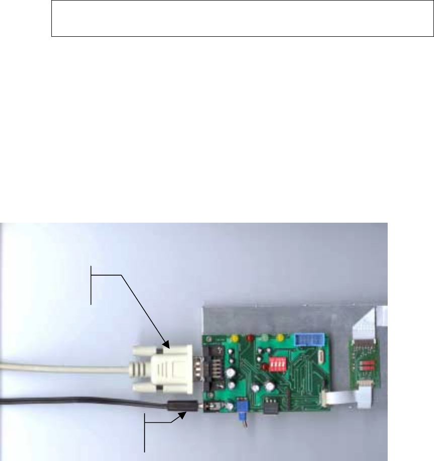
3.5.1. Installation and Connection
A D900SS-20 Demo Kit includes a plate that holds the B900ss-20 radio module, the
antenna and the RS232 interface card.
In order to use it, connect the plate to a PC's COM Port through the supplied serial
cable and connect the power supply (see picture).
On the interface card, ALL the switches have to be set to 'Off' and, of course, the
On/Off switch has to be on the 'On' position.
A Windows Software, 'WinB900' parameterizes and tests the B900ss-20 radio module.
In order to install it on your PC, launch 'Setup.exe' located on the CD-ROM supplied in
the Demo Kit, in the WinB900ss directory.
Serial
Connection to
a PC COM Port
Power Connector
(Battery or Power
Supply)
15
3.5.2. WinB900 Software Utilization in Point-to-Point Mode
The WinB900 Software can have two radio modules communicate between the COM1
and COM2 Port of a PC.
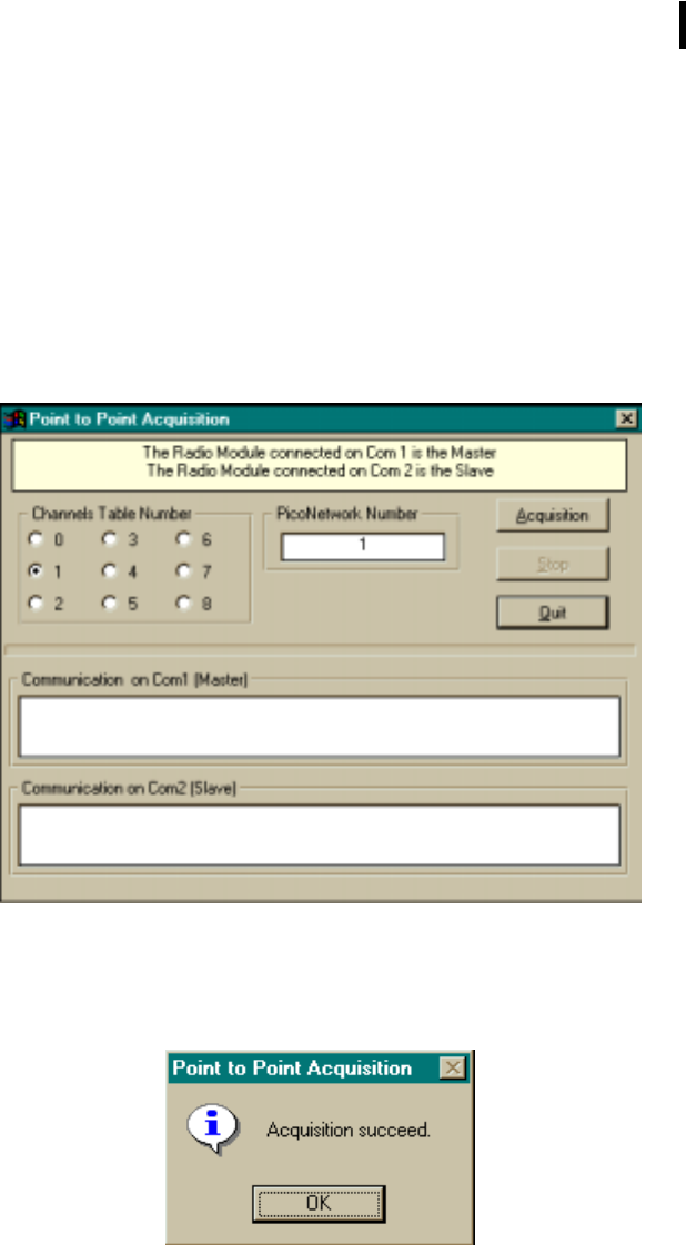
In a first phase, the two modems have to recognize each other ("Acquisition"). Go in
the "Quick Configuration" Menu, to the "Acquisition" Option. When this option is
selected, the software displays the following screen:
Select the table of the chosen channels as well as the No. of Personal network
(between 1 and 65535), and then launch the Acquisition clicking on the "Point-to-Point
Acquisition" button.
After clicking the button, the following message appears:
You can then quit the window. The Modems are synchronized (Green Led on).
16
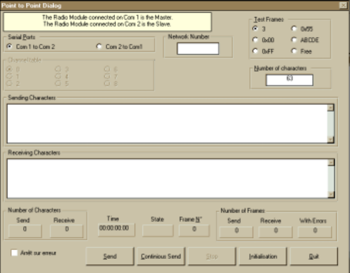
Consequently, you can communicate between the two Modems with the ‘Point-to-
Point Dialogue’ Option from the "Quick Configuration" menu. When this option is
selected, the software displays the following screen:
The different fields and buttons are described below:
• "Sent Characters" Field
This side of the window sends the data entry.
• "Received Characters" Field
This side of the window shows the received data.
• "Test Frames" Selection
This selection allows the selection for the type of character sent. For example,
0x00 sends a character frame only made of a 0x00 binary character.
If the "Free" frame type is selected, the frame can be typed by the user in the
"Sent Character" field. This frame will then be sent.

17
• "Characters Count" Field
This field allows the selection of the character count to be sent if the selected test
frame type is any other than "free".
• Button: "Send"
This button sends the frame entered previously to the Characters section to be
sent.
• Button: "Continuous"
This button sends continuously the frame entered previously to the Data section
to be sent.
• Button: "Initialization"
This button reinitializes all the counter fields (Elapse Time, Character Count,
Frame Count, etc.)
• Button: "Stop"
This button stops a continuous upload.
• Button: "Quit"
This button leaves this window and returns to the main menu.
• "Character Count Sent/Received" Fields
These fields show the sizes of the sent and received frames.
• "Elapsed time" Field
This field shows how long it takes the modem to upload the same frame during a
continuous upload.
• "Sent/Received/Corrupted Count" Fields
These fields show the amount of frames correctly uploaded, downloaded or
corrupted (or not received) since the start of a continuous upload.
• "Stop on Error" Selection
This selection stops automatically the continuous upload if a frame is corrupted.
18
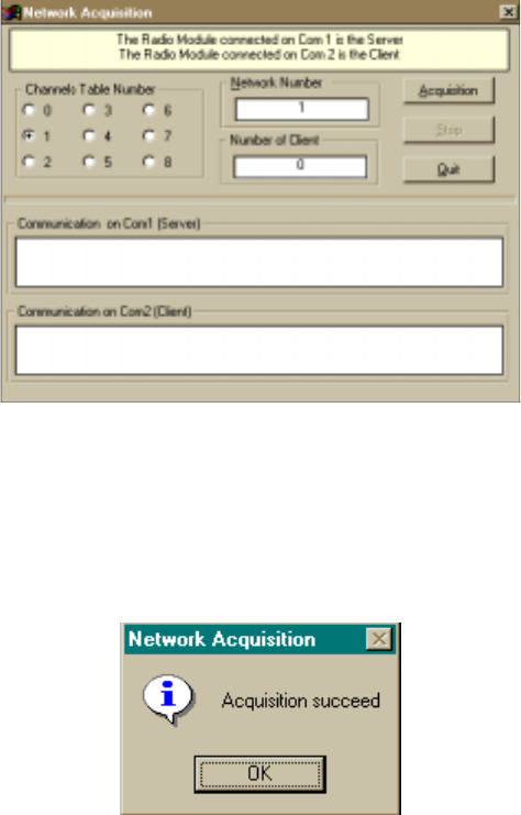
3.5.3. Use of the WinB900 Software in Network Mode
The operating principle is similar to the Point-to-Point Mode.
In a first phase, the two modems have to recognize each other ("Acquisition"). Go in
the "Quick Configuration" Menu, to the "Network Acquisition" option. When this
option is selected, the software displays the following screen:
It should be noticed that if the Modem already holds a Network Number and Clients,
these two pieces of information will display in the "Network No." and "Clients Count".
If the Network No. is modified, the Server will then lose all the Clients already acquired.
Acquisition can be launched by clicking on the "Acquisition" button. After this, the
following message is displayed:
You can then quit the window. The Modems are synchronized (Green Led (On).
19
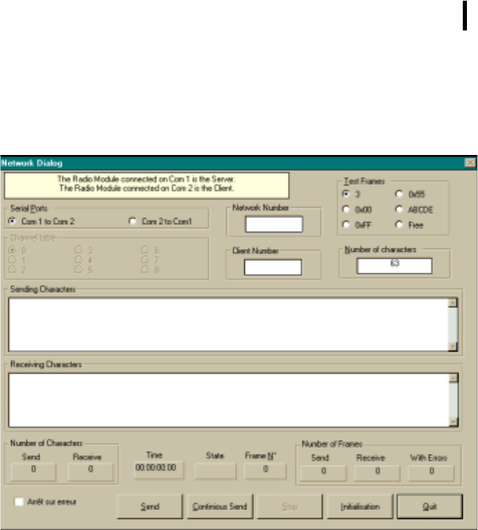
You can then communicate between the two Modems with the ‘Network Dialogue’
Option from the "Quick Configuration" Menu. When you pick this option, the software
displays the following:
The different fields and buttons are similar to the ones described in the previous
paragraph at the "Point-to-Point Dialogue" window. Only two new fields appear:
• "Network Number"
This field indicates the Network No. in the Server (COM1).
• "Client Number"
This field indicates the Modem No. in the Client (COM2).
20
3.5.4. Use of the "Terminal" or "HyperTerminal" Software
The Demo Kit or the B900ss-20 radio modules can also be handled from a Windows "HyperTerminal" or
"Terminal" type communication software.
The software has to be configured, in order to communicate at 19200 Baud, 8 bits, no parity, 1 stop bit through a
Serial link. To start with a correct configuration for HyperTerminal and Terminal, the following directories are
provided:
• "B900-CM1.ht" for "HyperTerminal" on COM1.
• "B900-CM2.ht" for "HyperTerminal" on COM2.
• "B900-CM1.trm" for "Terminal" on COM1.
• "B900-CM2.trm" for "Terminal" on COM2.
In this case, if your modems have already been configured and already been "Acquired", you can send data
frames with these software immediately. Otherwise, refer to Chapter 4 (Advanced Operation) to know how to use
the Registers.

21
Chapter 4. Advanced Operation
4.1. General
The section "Basic Operation" showed us how to operate the B900ss-20 Radio Module
and its D900SS-20 Demo Kit.
This section's objective is to know the module more completely; particularly the Hayes
commands necessary to handle the modem.

22
4.2. "Hayes" Protocol Commands
4.2.1. General
These commands configure the Modem assigning different values in the registers (S200
and next). They also enable the user to know the state of the registers and the version
of the modem software. These frames can only be sent if the CTS signal is active except
when in Acquisition Mode.
These commands support the 'Hayes' protocol used by the voice Modems. When a
When a When a
When a
command is sent, it
command is sent, it command is sent, it
command is sent, it always has to be preceded
always has to be precededalways has to be preceded
always has to be preceded by the 'AT' characters (ATtention).
by the 'AT' characters (ATtention). by the 'AT' characters (ATtention).
by the 'AT' characters (ATtention).
When a command has been sent, it
When a command has been sent, it When a command has been sent, it
When a command has been sent, it always has to be followed
always has to be followedalways has to be followed
always has to be followed by the <CR> character
by the <CR> character by the <CR> character
by the <CR> character
(carriage return, Hexadecimal 0x13 code).
(carriage return, Hexadecimal 0x13 code).(carriage return, Hexadecimal 0x13 code).
(carriage return, Hexadecimal 0x13 code).
NOTE:
NOTE:NOTE:
NOTE: The time slot between two characters of the command has to be inferior to
Time-Out (S214). As a result, the commands have to be sent by block:
A T Command Additive command ... <CR>
The sole exception
The sole exception The sole exception
The sole exception is the passing command from the Operation Mode in progress
is the passing command from the Operation Mode in progressis the passing command from the Operation Mode in progress
is the passing command from the Operation Mode in progress to
to to
to
the Hayes Mode: In this case,
the Hayes Mode: In this case,the Hayes Mode: In this case,
the Hayes Mode: In this case, the escape code ('+++')
the escape code ('+++') the escape code ('+++')
the escape code ('+++') has to be followed and
has to be followed and has to be followed and
has to be followed and
preceded by a silence period that lasts at least the same as time out. In this case only,
preceded by a silence period that lasts at least the same as time out. In this case only, preceded by a silence period that lasts at least the same as time out. In this case only,
preceded by a silence period that lasts at least the same as time out. In this case only,
the command will neither be preceded by AT, nor followed by <CR>
the command will neither be preceded by AT, nor followed by <CR>the command will neither be preceded by AT, nor followed by <CR>
the command will neither be preceded by AT, nor followed by <CR>
These commands are described in detail in the next chapter.

23
4.2.2. Description of the standard commands
Here is a description of possible commands:
'+++':
'+++': '+++':
'+++':
Running in Hayes Mode.
Running in Hayes Mode.Running in Hayes Mode.
Running in Hayes Mode.
This command allows the user to return to Hayes Mode when the Modem
is in "Point-to-Point" Mode. It cannot be preceded by AT, only by an idle
time (blank) that can be set through the S214 register for the duration.
NOTE: When the Modem runs in "AT" Mode, it is no longer in radio
receiver.
'ATO':
'ATO': 'ATO':
'ATO':
Running in "Point
Running in "PointRunning in "Point
Running in "Point-
--
-to
toto
to-
--
-Point" Mode.
Point" Mode.Point" Mode.
Point" Mode.
This command allows the user to run the Modem in "Point-to-Point"
Mode. To retrieve the "Hayes" Mode, send out the sequence ‘+++’.
'ATSn?':
'ATSn?': 'ATSn?':
'ATSn?':
Display of the S Number n Register content.
Display of the S Number n Register content.Display of the S Number n Register content.
Display of the S Number n Register content.
The content of the B900ss-20 operating parameters are found in named
'S' registers, and are numbered as described in Chapter VII- 3. Some
parameters are standard for all the Hayes Modems; others are specific to
B900ss-20.
(See Table in Appendix 6).
If the requested register is correct, the modem responds: ''Sxxx=yyy" with
xxx: register number and yyy: register content.
If the requested register is incorrect, the modem responds with the error
character 'E' (0x45).
These parameters are saved in EEPROM Memory and automatically
reloaded during a reset or when powered up.
'ATSn=m':
'ATSn=m': 'ATSn=m':
'ATSn=m':
Assi
AssiAssi
Assignment to the m Value at the S Register n Number.
gnment to the m Value at the S Register n Number.gnment to the m Value at the S Register n Number.
gnment to the m Value at the S Register n Number.
Loading of a parameter in a register. This parameter is automatically saved
in EEPROM Memory.
The n and m values are given in ASCII coded decimals. If the assigned
register is correct, the modem responds with the OK character 'O' (0x4F).
If the assigned register is incorrect or if the value goes over the limits of this
register, the modem responds with the error character 'E' (0x45).
'AT/S':
'AT/S': 'AT/S':
'AT/S':
Content Uncoded Display of all Significant Records.
Content Uncoded Display of all Significant Records.Content Uncoded Display of all Significant Records.
Content Uncoded Display of all Significant Records.
24
All the Modem significant registers (radio configuration, serial
configuration, operating mode...) are sent on the serial link uncoded, ready
to be displayed using a software such as "Terminal" for Windows.
The response is a list of all the used registers with their value, each register
being separated from the other with the "Carriage Return" character (CR):
"S200=xx<CR>S201=yy<CR>…."
'AT/V':
'AT/V': 'AT/V':
'AT/V':
Uncoded Display of the Modem Software Version.
Uncoded Display of the Modem Software Version.Uncoded Display of the Modem Software Version.
Uncoded Display of the Modem Software Version.
The information on the version number, conception date and the program
CRC are sent to the uncoded serial link, ready to be displayed using a
software such as "Terminal" for Windows.
The response is as follows: "Version: x.xx<CR> Date: MM/JJ/AAA<CR>
CheckSum: 0xhhhh<CR>"
'ATM1':
'ATM1': 'ATM1':
'ATM1':
Running in Acquisition Mode.
Running in Acquisition Mode.Running in Acquisition Mode.
Running in Acquisition Mode.
This command allows to toggle from Normal Mode to Acquisition Mode.
The Modem is in Normal Mode by default.
If the command is given correctly, the modem responds with the OK
character 'O' (0x4F), otherwise with the error character 'E' (0x45).
'ATPx':
'ATPx': 'ATPx':
'ATPx':
Running in Standby
Running in StandbyRunning in Standby
Running in Standby or Normal mode.
or Normal mode. or Normal mode.
or Normal mode.
This command allows the user to toggle from Normal Mode to Standby
Mode and vice versa, according to the 'x' value. The Modem is in Normal
Mode by default.
Then there is: x = '0' ! Normal,
x = '1' ! Standby.
If the command is correctly given, the modem responds with the OK
character 'O' (0x4F), otherwise with the Error character 'E' (0x45).
'ATR':
'ATR': 'ATR':
'ATR':
Parameters Reset.
Parameters Reset.Parameters Reset.
Parameters Reset.
This command allows the user to reprogram ALL the stored EEPROM
registers and give them their value by default.
If the command is correctly given, the modem responds with the OK
character, 'O' (0x4F), otherwise with the Error character 'E' (0x45).
4.2.3. Registers Description
This section is available in Appendix 6.

25
4.3. Utilization Example
4.3.1. Acquisition of two Point-to-Point Modems
To send the following commands to the Modem, it is necessary to use software such as HyperTerminal for
Windows.
• Parameterization of the "Master" Modem" :
User: +++ /* run in Hayes Mode. */
Modem response: O<CR>
User: ATS200=3<CR> /* Choice of Frequency table 3. */
Modem response: O<CR>
User: ATS201=0<CR> /* Choice of No. 1 Synchronization
Frequency. */
Modem response: O<CR>
User: ATS202=10<CR> /* Choice of No. 2 Synchronization Frequency. */
Modem response: O<CR>
User: ATS203=20<CR> /* Choice of No. 3 Synchronization Frequency. */
Modem response: O<CR>
User: ATS204=30<CR> /* Choice of No. 4 Synchronization Frequency. */
Modem response: O<CR>
User: ATS220=2<CR> /* Choice of Master Mode. */
Modem response: O<CR>
User: ATS250=1<CR> /* Choice of Personal Network No. */
Modem response: O<CR>
User: ATM1<CR> /* Run in Acquisition Mode */
Modem response: O<CR>
The user now must configure the Slave Modem (see next page). Once this configuration has been
done and the "ATM1" command activated, they acquire themselves and the Master Modem
returns: S252=1<CR> /* Indicates Acquisition done */
26
User: AT0<CR> /* Run in Point-to-Point Mode */
Modem response: O<CR>

27
• Parameterization of the "Slave" Modem:
Before parametering the Slave Modem, the Server must have been configured and must be in
Acquisition Mode.
User: +++ /* Run in Hayes Mode. */
Modem response: O<CR>
User: ATS200=3<CR> /* Choice of the Frequency Table 3. */
Modem response: O<CR>
User: ATS201=0<CR> /* Choice of No. 1 Synchronization Frequency. */
Modem response: O<CR>
User: ATS202=10<CR> /* Choice of No. 2 Synchronization Frequency. */
Modem response: O<CR>
User: ATS203=20<CR> /* Choice of No. 3 Synchronization Frequency. */
Modem response: O<CR>
User: ATS204=30<CR> /* Choice of No. 4 Synchronization Frequency. */
Modem response: O<CR>
User: ATS220=3<CR> /* Choice of Slave Mode. */
Modem response: O<CR>
User: ATS250=0<CR> /* Indicates Uncoded Slave (No Personal Network No.).
*/
Modem response: O<CR>
User: ATM1<CR> /* Runs in Acquisition Mode */
Modem response: O<CR>
At this time, the two Modems have to acquire themselves, and the Slave Modem sends:
Modem response: S250=1<CR>S252=1<CR> /* Indicates Acquisition
done */
User: AT0<CR> /* Runs in Security Transparent Mode */
Modem response: O<CR>
28
4.4. Radio Test Commands
These Special AT commands are integrated in the B900ss-20 in order to measure in
continuous emission, and are primarily used during radio tests (radiated power, line
width, etc.) to respect the Part15-247 FCC standard.
It stops when any character is sent:
• ATT0: Transfer of a pure carrier with the frequency chosen by
the channel command.
• ATT1: Transfer of a modulated carrier '00'.
• ATT2: Transfer of a modulated carrier '01'.
• ATT3: Transfer of a modulated carrier '10'.
• ATT4: Transfer of a modulated carrier '11'.
NOTE: the character <CR> follows each command.
29
4.5. Utilization of WinB900
4.5.1. Hayes commands
The parameterization with the Hayes commands can be simply done with the WinB900
software.
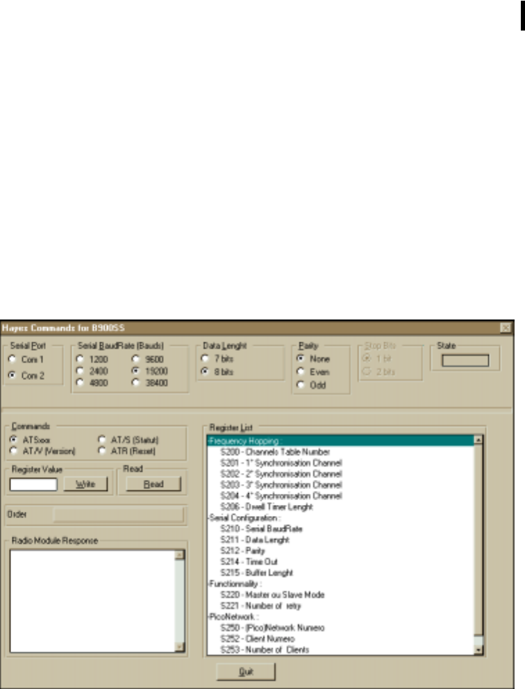
The option "Hayes Commands" of the "Advanced Configuration" allows to perform all
of the Hayes Commands on the modems connected to the PC.
When this option is selected, the software displays the following window:
The top section allows the user to select the port to work on and describes the state of
the serial link (speed, parity, etc.). The serial link state is not directly modifiable: It will
follow the evolution of the values in S210 to S213 registers.
The bottom end sends Hayes commands. All the Registers are present with the content
explanation for each of them.

30
There are four types of possible manipulation:
" Read/Write on the Registers: Select the "ATSxxx" option in the "Available
Commands", then select the required register clicking on it in the "Registers List".
• If you want to read a register, click now on the "Read" button. The "Syntax"
window will display the sent command while the "Radio Module Response"
window will display the B900SS response.
• If you want to write in a register, indicate the value that you want to give to
this register in the "Register Value" window, then click on the "Write"
Button. The "Syntax" window will display the sent command while the
"Radio Module Response" window will display the B900SS response.
" Read the Firmware Version: Select the "AT/V" option in the "Available
Commands", then click on the "Read" button. The "Syntax" window will display
the sent command while the "Radio Module Response" will display the B900SS
response.
" Read the Status Information: Select the "AT/S" option in the "Available
Commands", then click on the "Read" button. The "Syntax" window will display
the sent command while the "Radio Module Response" window will display the
B900SS response.
" Registers Reset to the default value: Select the "ATR" option in the "Available
Commands", then click on the "Read" button. The "Syntax" window will display
the sent command while the "Radio Module Response" will display the B900SS
response.
31
4.5.2. Test Commands (Future software option – Not available at this time)
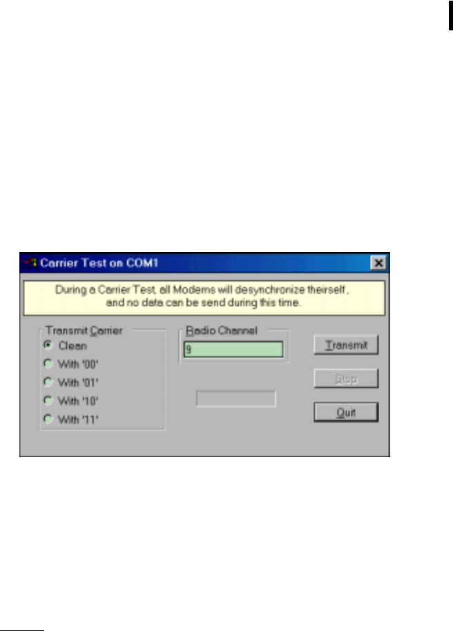
Carrier Transmission Tests can also be simply realized with the WinB900 Software.
The "Carrier Test" option of the "Advanced Configuration" Menu allows to test Carrier
Transmission from a radio module.
When this option is selected, the software displays the following window:
• "Carrier Transmission" Selection
Through this window, it is possible to transmit several types of carrier to check the
power and the signal modulation. Here are the following Carrier’s choices:
• Pure
• Modulated at ‘00’
• Modulated at ‘01’
• Modulated at ‘10’
• Modulated at ‘11’
Remark:
If a transmission is in progress and you want to change the carrier type, it is
imperative to stop the transmission before selecting another carrier, otherwise
your change will not take effect
• "Radio Channel" Field
This Field available for input specifies the radio channel where the selected carrier
will be transmitted from.
32
• "Transmission" Button
This button allows initiating the selected carrier transmission based on the chosen
channel. When this button is selected, a red rectangle appears indicating that the
modem is transmitting.
• "Stop" Button
This button stops transmitting the selected carrier.
• "Quit" Button
This button returns to the Main Window.
33
Appendix
AppendixAppendix
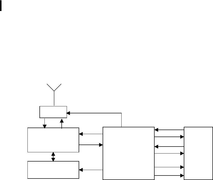
Appendix 1: Schematic Block Diagram
1: Schematic Block Diagram 1: Schematic Block Diagram
1: Schematic Block Diagram
902 MHz
Transmitter/
Receiver
RF
Switch
PLL
MicroController
+
EEPROM Memory
Interface
RxD
TxD
CTS
RTS
Ack_Tx
Lock
34
Appendix 2: Mechanical Drawings
Appendix 2: Mechanical DrawingsAppendix 2: Mechanical Drawings
Appendix 2: Mechanical Drawings
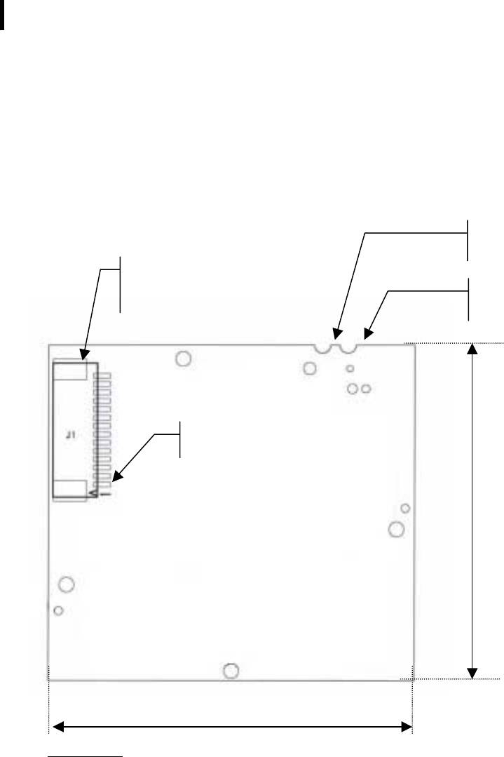
Drawing of the B900ss-20 Card
WARNING :
WARNING :WARNING :
WARNING : In the "Rev. A" version of the card, the 1° connector contact of the J1 interface
In the "Rev. A" version of the card, the 1° connector contact of the J1 interface In the "Rev. A" version of the card, the 1° connector contact of the J1 interface
In the "Rev. A" version of the card, the 1° connector contact of the J1 interface
(corresponding to the RTS Signal) is "below", as shown on the schematic.
(corresponding to the RTS Signal) is "below", as shown on the schematic. (corresponding to the RTS Signal) is "below", as shown on the schematic.
(corresponding to the RTS Signal) is "below", as shown on the schematic.
In future ("Rev. B, Rev C, etc.” versions, the 1° connector contact of the J1 interface
In future ("Rev. B, Rev C, etc.” versions, the 1° connector contact of the J1 interface In future ("Rev. B, Rev C, etc.” versions, the 1° connector contact of the J1 interface
In future ("Rev. B, Rev C, etc.” versions, the 1° connector contact of the J1 interface
(corresponding to the RTS Signal) will be "above", meaning on the opposite side of its actual
(corresponding to the RTS Signal) will be "above", meaning on the opposite side of its actual (corresponding to the RTS Signal) will be "above", meaning on the opposite side of its actual
(corresponding to the RTS Signal) will be "above", meaning on the opposite side of its actual
position.
position.position.
position.
1.71"
1.57"
Interface Connector
(14FMS-1.0SP-TF) Ground Antenna
(Cold Point)
Antenna Hot Point
1° Connector Contact
(RTS)

35
Interface Signals
The Modem will communicate with the host through an interface with the following
signals:
Bus
Pin Interface Function Signal
direction
µC*
µC Function
1 RTS
Or Data Out SPI (1) O RTS ! Request To Send
Data Out SPI ! Data out during the programming of the Flash
Program.
2 Ack_Tx
Or Clock In SPI (1) I/O Ack_Tx ! Transmission Ok
Clock In SPI ! Clock In during the programming of the Flash
Program.
3 N.U. - -
4 RXD I RxD UART - Serial Data Reception
5 CTS
Or Data In SPI (1) I CTS ! Clear To Send
Data In SPI ! Data In during the programming of the Flash
Program.
6 TXD O TxD UART - Serial Data Transmission
7 VDD - 5 volts power for digital ("noisy").
8 LOCK O Network Synchronization Ok.
9 RESET I External Reset. Also used during the programming of the Flash
Program.
10 GND - Ground
11 N.U. I -
12 N.U. I -
13 N.U. I -
14 N.U. I -
((1): SPI hardware only in slave. The user is connected to this bus only in Flash/EEPROM
Programming: In this case, the RESET signal has to be on.
*I = Input O = Output
NOTE: The connector used is the 14FMS-1.0SP-TF 14-pin manufactured and distributed by
JST.

36
Signals Description
N.U.: Not used. By default, these signals are linked to the micro-controller,
configured at input but are not actually used.
LOCK: Solely used on the Portable: Indicates that the synchronization with the
Base is valid. Latter indicates if the Server is at radio range. Active on
high.
RESET: Reset hardware of the modem card. Maximum Duration: 200 ms. Active
on low.
ACK_TX: Indicates that the buffer transmission has been executed correctly. This
signal is valid at the end of the transmission of a radio message (Active
RTS Signal) and is kept until RTS returns to inactive. Active (buffer
transmitted) on low.
xx SPI: Signals for the Flash or the EEPROM programming of the Modem from
the host. There are three signals: Data In, Data Out and Clock.
When the host wants to read and/or modify the EEPROM, the modem
must absolutely be in reset by activating the RESET Signal.
CTS: Clear To Send: signal into the Modem. Indicates if the Modem can send
serial data to the User (Active on low) or not (Inactive on high).
RTS: Request To Send: signal going out of the Modem. Indicates that the user
can transmit serial data (Active on low) or not (Inactive on high). This
signal switches when the serial reception buffer's filling rate reaches a
programmable threshold (S215) or when the user finished to transmit
serial data (out on Time-Out).
TxD, RxD: Serial link signals in NRZ/TTL format. TxD is for the data going out of the
Modem while RxD is for the data coming into the Modem. Le logic '1' is
represented by high.
37
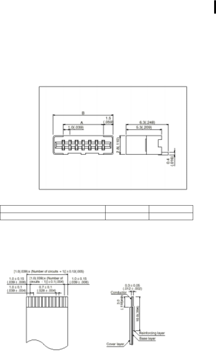
Connector Drawing
The selected connector is the 14FMS-1.0SP-TF from the JST Manufacturer. It is a CMS
and non-ZIF (Zero Insertion Force) 14-pin angled connector with a spacing of .039".
With: Connector
ConnectorConnector
Connector
A (inch)
A (inch)A (inch)
A (inch)
B (inch)
B (inch)B (inch)
B (inch)
14FMS-1.0SP-TF (14-pin) .511 .630
Connecting Cable Drawing
The associated cable should have the following dimensions:
38
Appendix 3: Ant
Appendix 3: AntAppendix 3: Ant
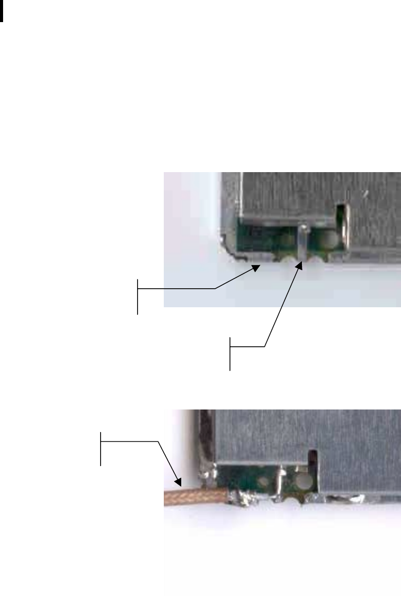
Appendix 3: Antenna Connection
enna Connectionenna Connection
enna Connection
Here is an example of the coaxial cable connection of the 900MHz antenna provided
with the Demo Kit. The hot and cold point can easily be seen before and after
soldering the cable.
Coaxial Cable
connected to the
antenna.
"Hot" point where to
connect the cable core.
"Cold" Point where to
connect the breading of the
cable
(g
round
)
.
39
Appendix 4: D900SS
Appendix 4: D900SSAppendix 4: D900SS
Appendix 4: D900SS-
--
-20 Demo Kit
20 Demo Kit20 Demo Kit
20 Demo Kit
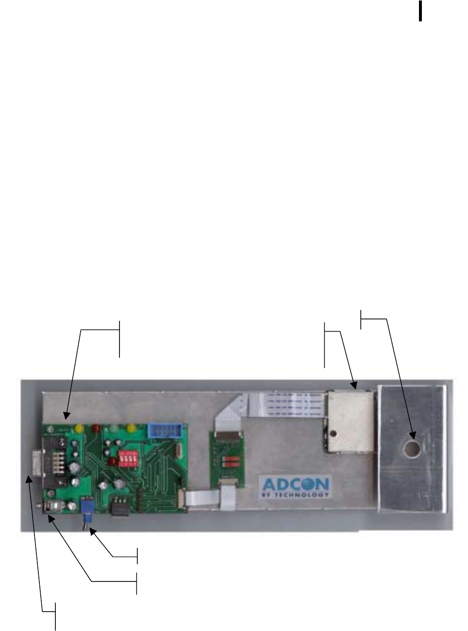
Composition
The D900SS-20 Demo Kit is used to test with ease the B900ss-20 radio module.
For this purpose, this kit connects a radio module to a serial interface in order to be
able to work with the radio module without having to develop a specific interface.
In addition, Windows configuration and test software is included with the kit and allows
working with the radio module immediately.
In a case, each D900SS-20 Demo Kit includes:
• Two metallic plates, with:
$ 2 900 MHz antenna,
$ 2 B900ss-20 radio module,
$ 2 interface cards connecting B900ss-20 and RS232,
• Two power supplies
• Two 9V batteries, allowing to manage without sector during field tests,
• A CD-ROM including this document in PDF Format and the "WinB900" Test and
Configuration Software for Windows.
B900SS-20
Radio Module
Radio Antenna
RS232
Version 1 Interface
Card
On/Off Switch
8-24V Power Supply Jack
9 pin RS232 Sub-D Connector
40
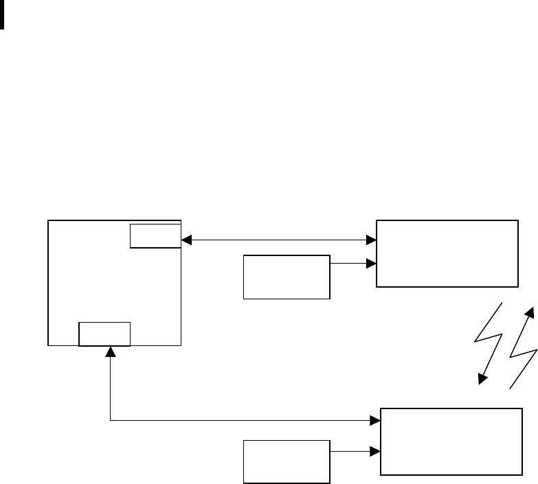
Connections
Here is how to make the connections to the Demo Kit in order to operate them with
the WinB900 Software:
No. 1 Radio Plate
(Master)
Windows 95/98
PC and two Serial
Ports
No. 2 Radio Plate
(Slave)
COM1
COM2
Power Supply
Power Supply
41
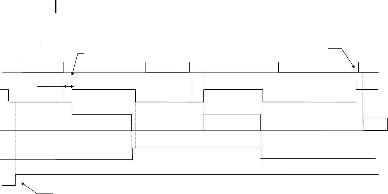
Appendix 5: Timing Diagrams
Appendix 5: Timing DiagramsAppendix 5: Timing Diagrams
Appendix 5: Timing Diagrams
The user sends data
TxD
RTS
Radio
Ack_Tx
Lock
Serial Data
Radio Transmission
Result: Error
TimeOut
Serial Data
Radio Transmission
Result: OK
Serial Data
Radio
Stop on CTS,
Len
g
th ≥ S215
Stop on TimeOut
Len
g
th<S215
If Slave, Master/Slave synchronization just ended correctly.
Active
active
inactive
inactive
42
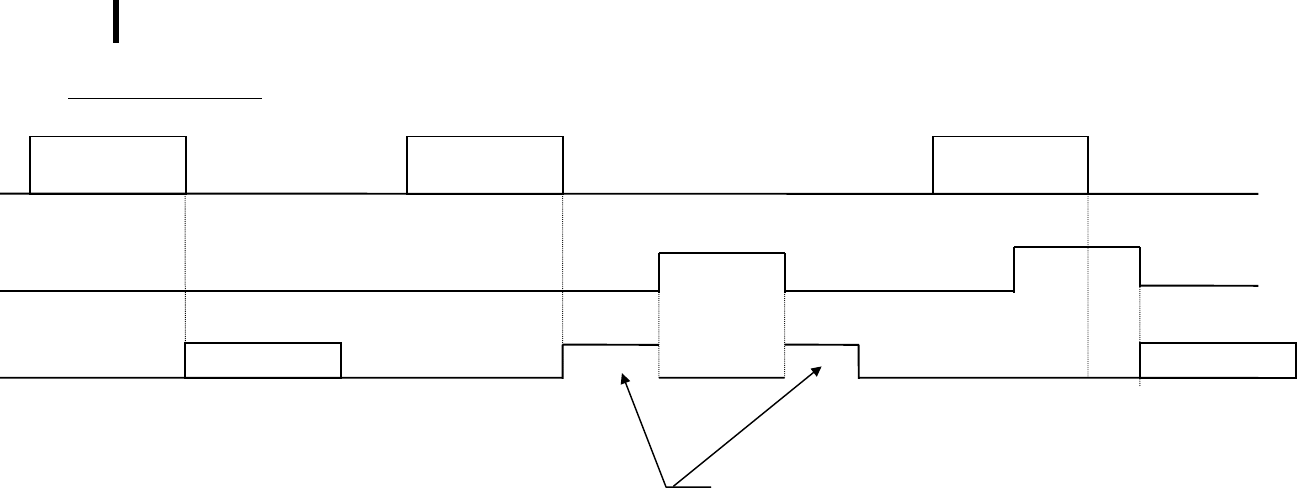
The user Receives data
Radio
CTS
RxD
The CTS signal indicates that the user reception buffer is full. Therefore, the modem does not send data on the serial link
during that time. However, the basic radio operation (synchronization, signal lock, etc.) and the data transmission on the radio
(with data reception on the serial link) continues to operate normally. On the other hand, if another modem sends a data
frame on the radio, this radio frame is not handled (and then not acknowledged). The Transmitter Modem considers this radio
frame as lost and indicates it to the user. (Ack_Tx signal).
It would be better to avoid making the CTS inactive as much as possible.
Data Reception
Serial Data
Data Reception
Serial Data cut in two.
Data Reception
Serial Data
inactive
active

43
Appendix 6: Description of the registers
Appendix 6: Description of the registersAppendix 6: Description of the registers
Appendix 6: Description of the registers
Registers used by the ‘AT’ protocol
This section shows a list of all the registers that configure the modems with software
such as HyperTerminal for Windows.
The B900ss-20 modem will offer several facilities of possible settings.
Each parameter will be in a register and will have a default value that can be changed
in sending the command 'ATSxxx=yy' (Hayes command). Also, the parameter value will
be read when sending the command 'ATSxxx?'.
These parameters are stored in the EEPROM memory and will be available as soon as
powered up.
NOTE: Access Type: 'R' Read and/or 'W' Write.
Access
Type Register Name Description
Frequency Jump
Frequency JumpFrequency Jump
Frequency Jump
R/W S200 No. of Used Frequency Table Between 0 and 8. When Table 0 is selected, the channels
remain the same and stay on the selected channel in S201 (used
for the tests).
Default: 1.
Default: 1.Default: 1.
Default: 1.
R/W S201 First Frequency reserved for
the synchronization. Between 0 and 49. Has to be different from S202, S203 and
S204.
Default: 0.
Default: 0.Default: 0.
Default: 0.
R/W S202 Second Frequency reserved
for the synchronization. Between 0 and 49. Has to be different from S201, S203 and
S204.
Default: 15.
Default: 15.Default: 15.
Default: 15.
R/W S203 Third Frequency reserved for
the synchronization. Between 0 and 49. Has to be different from S201, S202 et S204.
Default: 30.
Default: 30.Default: 30.
Default: 30.
R/W S204 Fourth Frequency reserved for
the synchronization. Between 0 and 49. Has to be different from S201, S202 et S203.
Default: 45.
Default: 45.Default: 45.
Default: 45.
R S206 Dwell Timer Length Calculated based on the serial connection speed (S210), the
buffer size (S215) and the Client Count (S253). Given in
milliseconds.
Default: 110 ms (38400 Bd/130 Bytes/1 client).
Default: 110 ms (38400 Bd/130 Bytes/1 client).Default: 110 ms (38400 Bd/130 Bytes/1 client).
Default: 110 ms (38400 Bd/130 Bytes/1 client).

44
Access
Type Register Name Description
Serial Link
Serial LinkSerial Link
Serial Link
R/W S210 Speed.
Indicates the speed on the Serial Connection
'2': 2400 Baud.
'3': 4800 Baud.
'4': 9600 Baud.
'5': 19200 Baud
'5': 19200 Baud'5': 19200 Baud
'5': 19200 Baud (Default)
(Default)(Default)
(Default).
'6': 38400 Baud
R/W S211 Data Bits (*) Serial Link Data Bits.
'7': 7 bits.
'8': 8 bits (Default).
'8': 8 bits (Default).'8': 8 bits (Default).
'8': 8 bits (Default).
R/W S212 Parity (*) Indicates Serial Link Parity Type:
'1': None (Default).
'1': None (Default).'1': None (Default).
'1': None (Default).
'2': Even.
'3': Odd.
R/W S214 Serial Link Time Out Time_Out in milliseconds. Between 2 and 100 milliseconds.
Default: 5 ms.
Default: 5 ms.Default: 5 ms.
Default: 5 ms.
R/W S215 Buffer Size Indicates the maximum size of the frames that will be given to the
Modem. When this size is reached, the modem resets the CTS
signal. It has to be inferior to the physical size of 130 Bytes.
Default: 130 Bytes.
Default: 130 Bytes.Default: 130 Bytes.
Default: 130 Bytes.
(*): The parity control requires some constraints and the serial configuration described
below can be reset:
S211
S211S211
S211
S212
S212S212
S212
Description
DescriptionDescription
Description
8 1 8 bits, no parity, 1 stop bit (8,N,1)
8 2 8 bits, even parity, 1 stop bit (8,E,1)
8 3 8 bits, odd parity, 1 stop bit (8,O,1)
7 2 7 bits, even parity, 1 stop bit (7,E,1)
7 3 7 bits, even parity, 1 stop bit (7,O,1)

45
Access
Type Register Name Description
Operation
OperationOperation
Operation
R/W S220 Server or Client Mode Indicates the operation of the Modem. When the Modem is
configured as Master (or Server), the S252 Register switches
automatically to 0xFF, while it switches to 0 when configured
as Slave (or Client).
'0' : Server (Network),
'1' : Client (Network),
'2' : Master,
'3': Slave (Default).
'3': Slave (Default).'3': Slave (Default).
'3': Slave (Default).
R/W S221 Recovery Count Maximum recovery count in case of problems (Non-Ack
response to a message).
If this Register is at 0, the frames are not checked and
considered as still good (used for the tests).
Default: 2.
Default: 2.Default: 2.
Default: 2.
P
PP
Personal Network Control
ersonal Network Controlersonal Network Control
ersonal Network Control
R/W S250
Number of Personal Network
(or Network)
This register gives the Personal Network (Network) number on
2 Bytes. Only the two members of a same Personal Network
can communicate with each other. Between 0 and 65535, it is
at 0 when the modem is not reset.
NOTE: To reset the register to 0 also resets the S252 Register
to 0.
Default: 0.
Default: 0.Default: 0.
Default: 0.
R S252 Modem Number Gives the Modem a unique number for a given Personal
Network. Number on one Byte is 0 when the Modem is not
reset, 1 if it is a Slave, between 1 and 6 if it is a Client and 255
if it is the Master.
Default: 0.
Default: 0.Default: 0.
Default: 0.
R S253 Clients Count Gives the Client count of a Master Modem or a Server.
Default: 0.
Default: 0.Default: 0.
Default: 0.
R/W S254 Client Addition Gives the number of a Client to be added in the already set
up network. This number should be between 1 and S253. Only
used on a Network Server.
Default: 0.
Default: 0.Default: 0.
Default: 0.

46
Appendix 7: Revisions History
Appendix 7: Revisions HistoryAppendix 7: Revisions History
Appendix 7: Revisions History
No. of
No. of No. of
No. of
Revision
RevisionRevision
Revision
Date
DateDate
Date
Author
AuthorAuthor
Author
Subject
SubjectSubject
Subject
0.0 01/08/00 GS Document Creation
0.1 08/08/00 GS Modifications after YN reading.
0.2 28/08/00 GS Addition of Network Specifications. Serial configuration MAJ.
0.3 10/10/00 SP English Text, Diagrams and Clarifications
0.4 1/26/01 SP Added FCC Disclaimers (Pages 6 & 16)
0.5 1/31/01 SP Changed Channel Spacing from 200 kHz to 150 kHz (Page 6)
0.6 4/20/01 SP Consolidated FCC Disclaimers to Page 5 and various other
miscellaneous corrections.
0.7 8/7/01 SP Added RF safety warning and removed antenna information per
FCC request