Ademco 20152824 E7 Thermostat User Manual
Honeywell International Inc E7 Thermostat
UserManual.wiki
>
Ademco
>
20152824 User Manual
>
User manual.pdf
Contents
1.
User manual.pdf
2.
User manual_e7 Install Instructions and Regulatory information_Rev 1.pdf.pdf
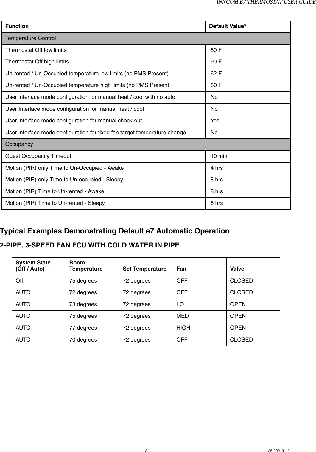
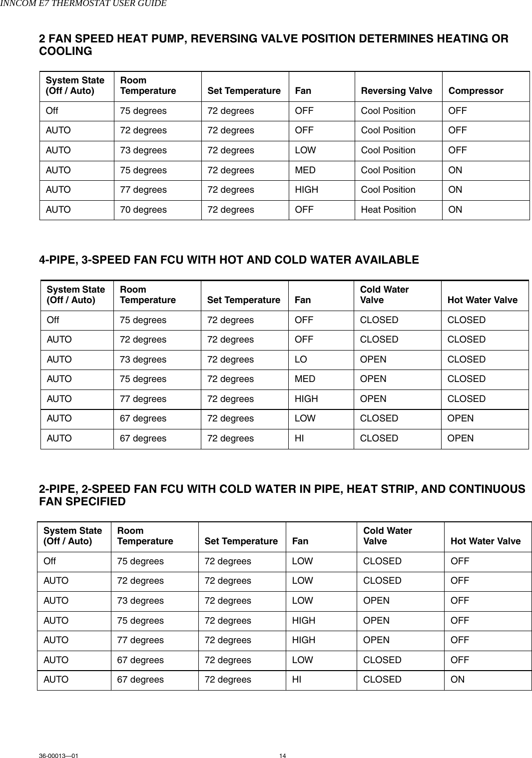
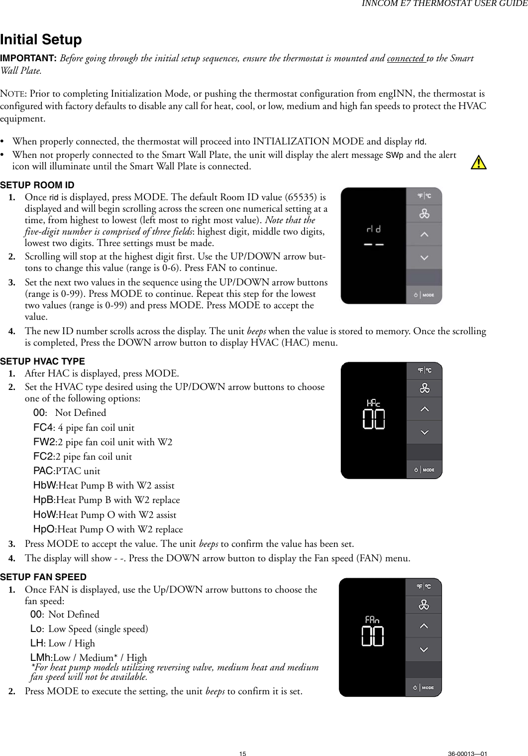
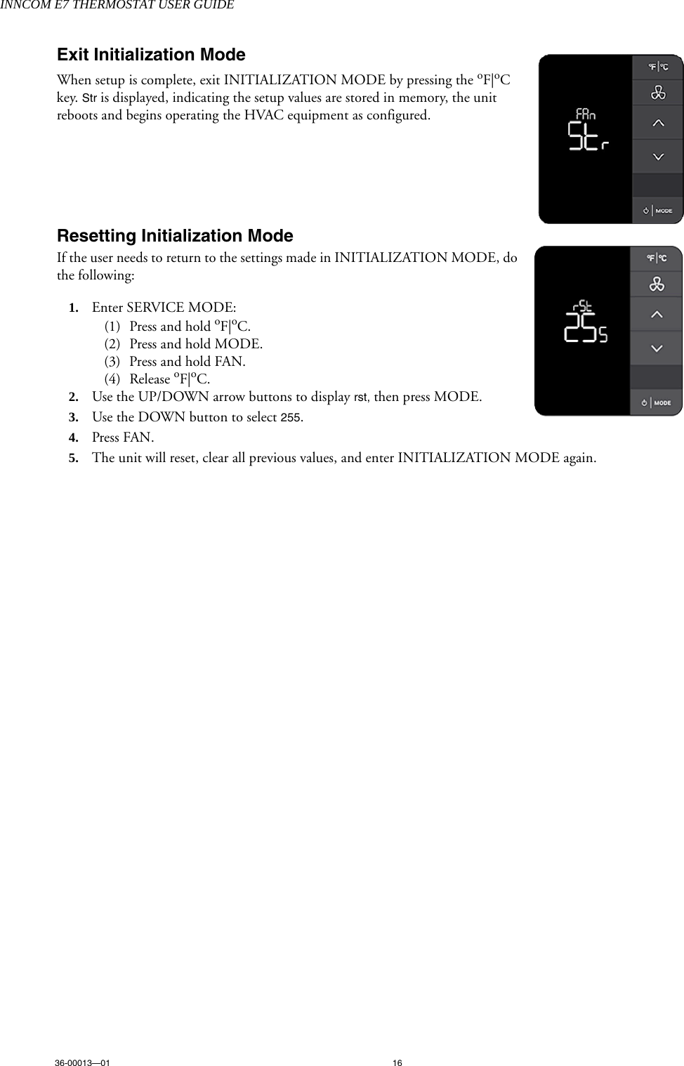
User manual.pdf
Navigation menu
Upload a User Manual
Namespaces
Wiki Guide
HTML
PDF
Info
Views
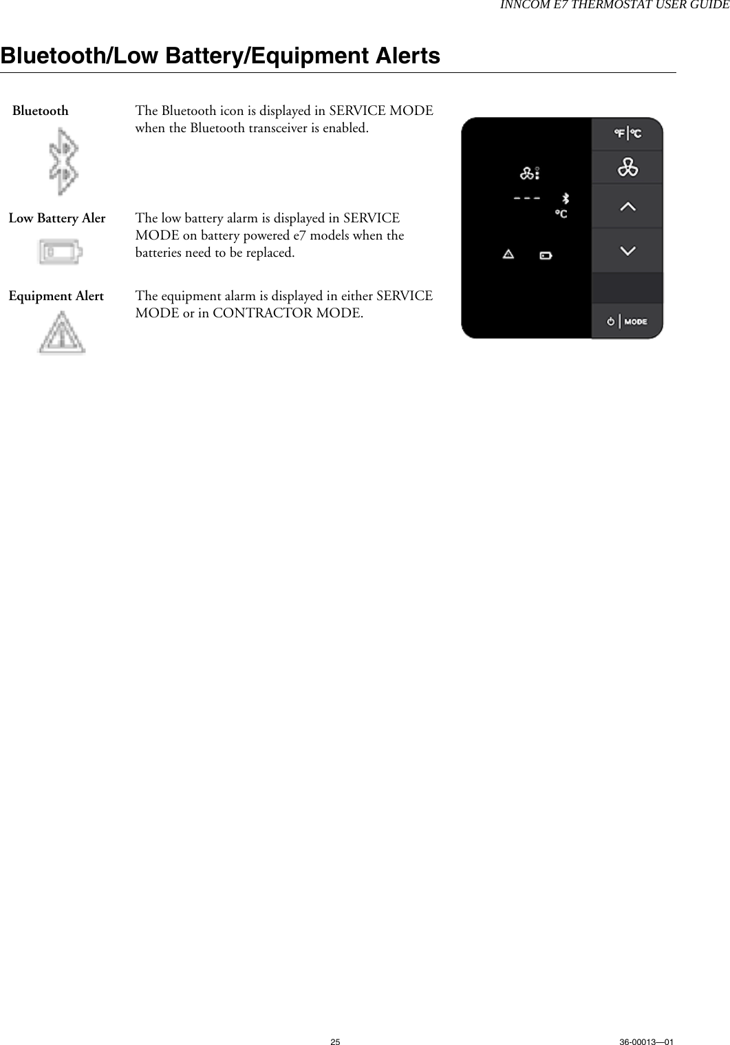
User Manual
Discussion / Help
Navigation