Ademco 50052669 Equipment Interface Module User Manual
Honeywell International Inc Equipment Interface Module Users Manual
UserManual.wiki
>
Ademco
>
50052669 User Manual
Users Manual
Navigation menu
Upload a User Manual
Namespaces
Wiki Guide
HTML
PDF
Info
Views
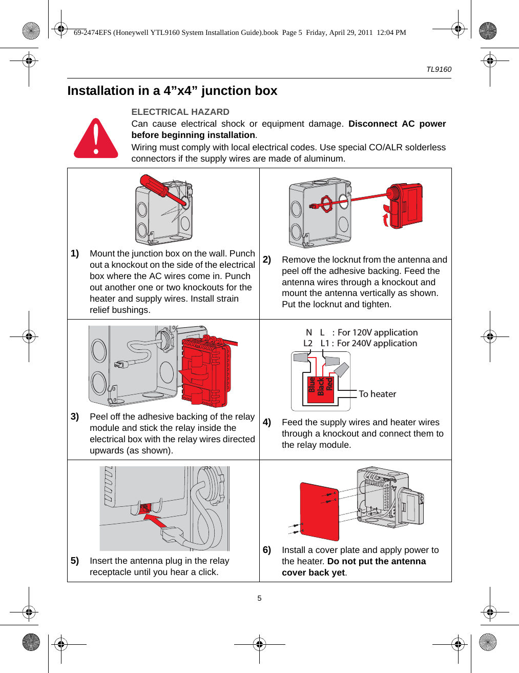
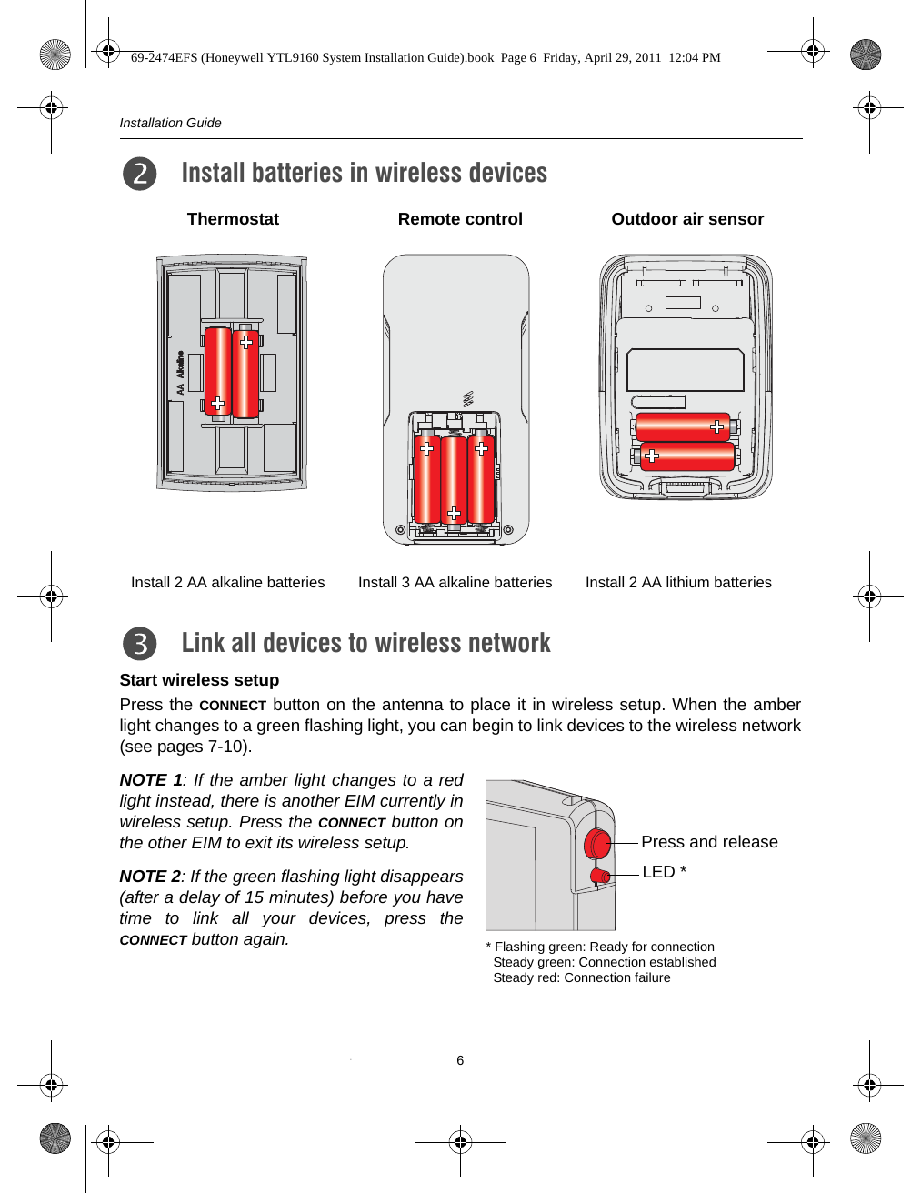
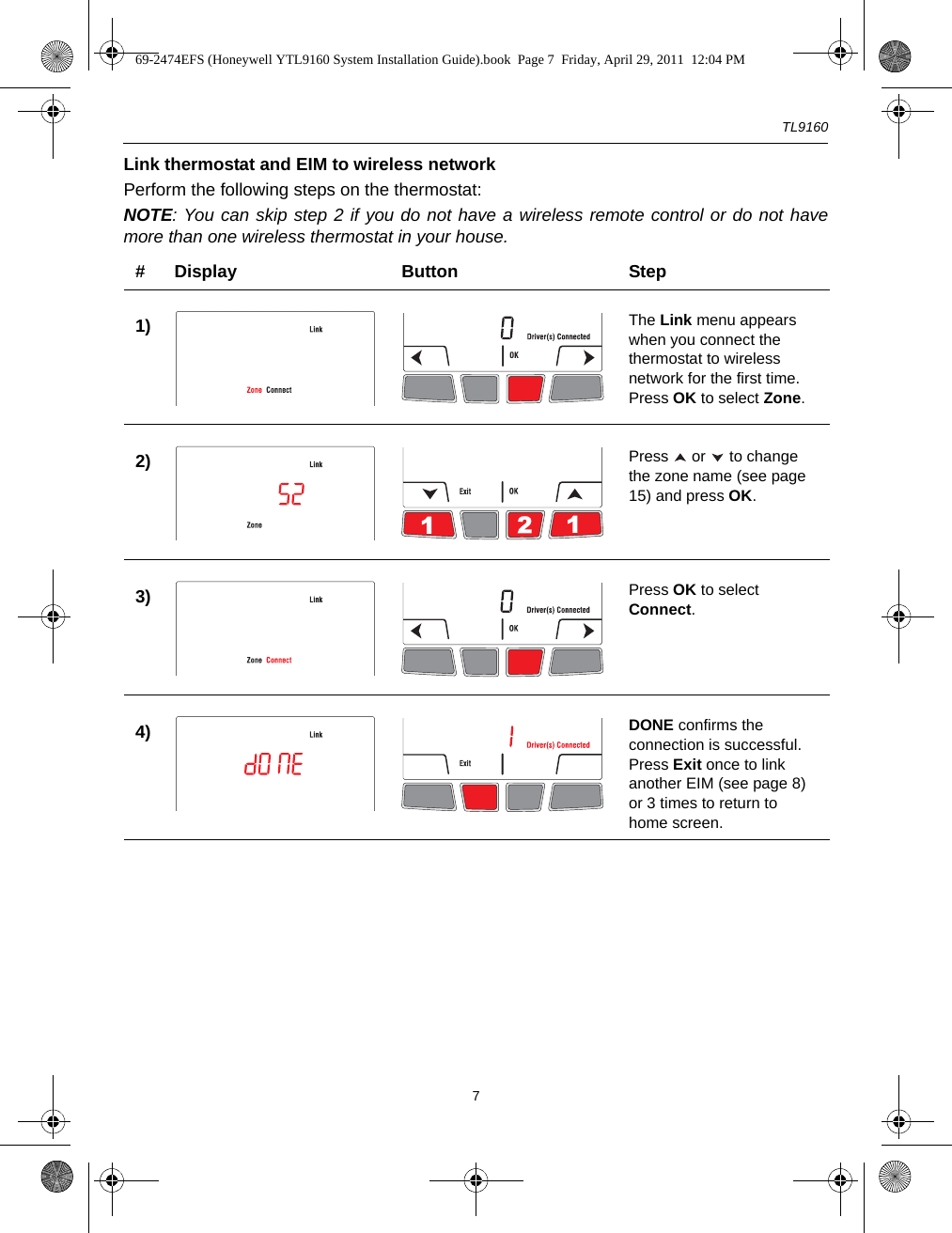
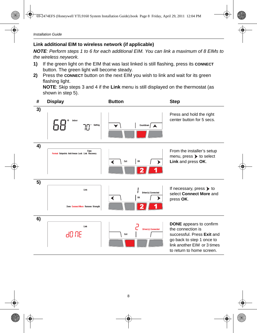
User Manual
Discussion / Help
Navigation