Ademco 50052669 Equipment Interface Module User Manual
Honeywell International Inc Equipment Interface Module Users Manual
Ademco >
Users Manual
TL9160 Wireless Thermostat Kit
With Equipment Interface Module
Installation guide for:
• Wireless equipment interface module
• TL9160 wireless thermostat
• Wireless remote control
• Wireless outdoor air sensor
IMPORTANT INSTRUCTIONS
Need Help?
For assistance with this product please visit http://customer.honeywell.com
or call Honeywell Customer Care toll-free at 1-800-468-1502.
Français : voir la page 25 • Espagnol : vea la página 49
ELECTRICAL HAZARD
Can cause electrical shock or equipment damage. Disconnect power
before beginning installation.
Must be installed by a trained, experienced technician. Read these
instructions carefully. Failure to follow these instructions can damage the
product or cause a hazardous condition.
System
Installation
Guide
69-2474EFS (Honeywell YTL9160 System Installation Guide).book Page 1 Friday, April 29, 2011 12:04 PM
Installation Guide
2
The equipment interface module (EIM) allows you to control a baseboard heater, a
convector or a fan-forced heater in 120-volt or 240-volt application from a TL9160 wireless
thermostat
Installation procedure
Install the equipment interface module (EIM)............................................... Pages 3 - 5
Install batteries in wireless devices..................................................................... Page 6
Link all devices to wireless network ............................................................. Pages 6 - 9
Exit wireless setup ............................................................................................ Page 10
Customize thermostat (installer setup)..................................................... Pages 10 - 17
Mount thermostat and outdoor sensor .............................................................. Page 18
For error codes, see page 19.
To verify the signal strength, see page 20.
To replace a wireless device, see page 20.
For specifications and replacement parts, see page 22.
SAVE THESE INSTRUCTIONS
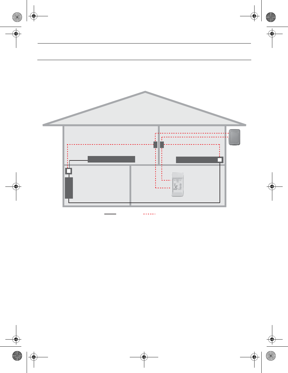
System installation at a glance
1.
Remote
control
Thermostat Outdoor
sensor
Thermostat
EIM in remote
junction box
EIM inside heater
Electrical
panel
heater
Supply wires Wireless connection
69-2474EFS (Honeywell YTL9160 System Installation Guide).book Page 2 Friday, April 29, 2011 12:04 PM
TL9160
3
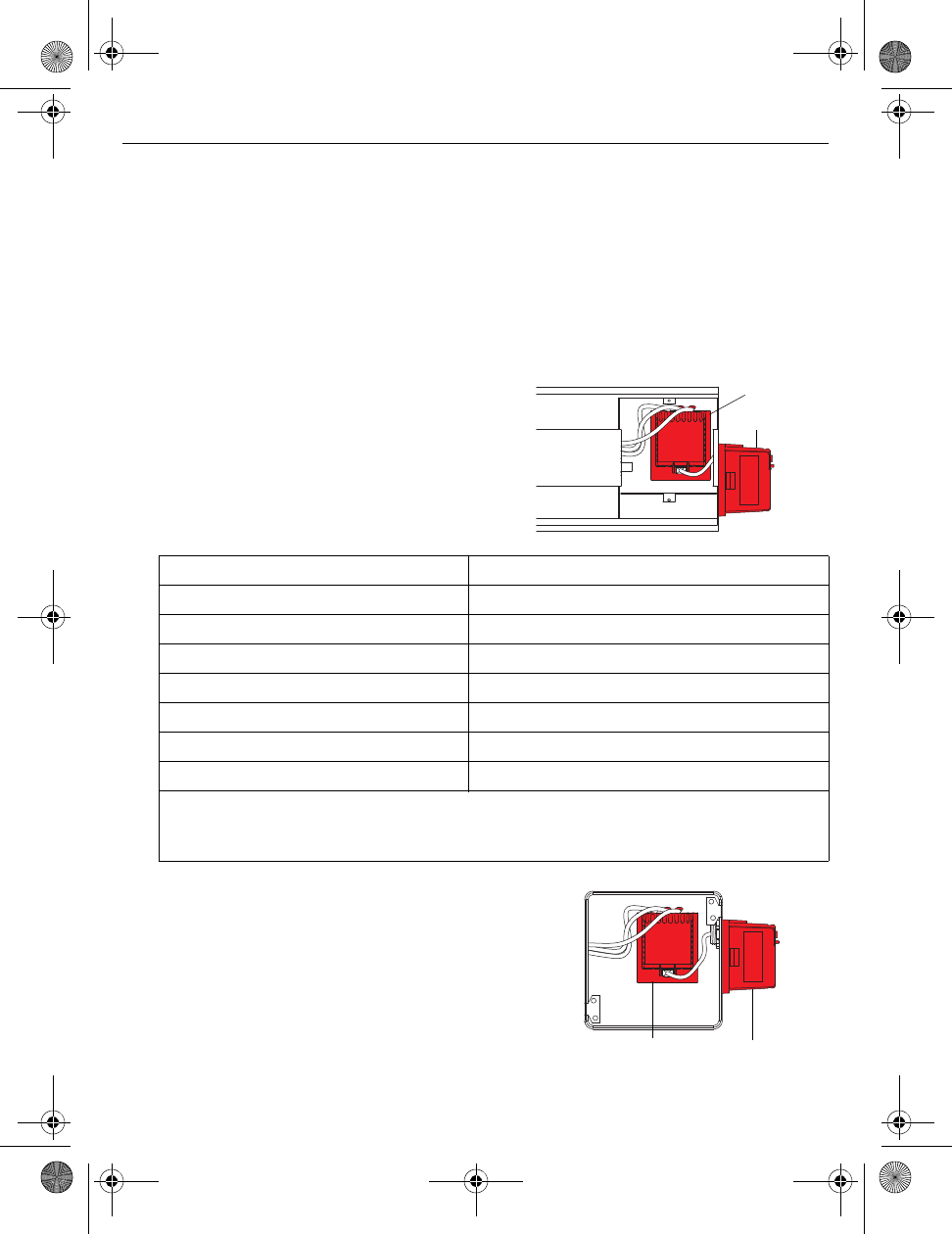
Determine the location
The equipment interface module (EIM) consists of a relay and an antenna. They can be
installed either in the wiring compartment of the baseboard heater or in a 4”x4” junction
box.
NOTE: Install EIMs at a minimum distance of 2 feet (0.6 m) of each other. This minimum
distance still applies even if the EIMs are on opposite sides of a wall.
• Installing the EIM in the baseboard heater
You can install the EIM in the wiring
compartment of the heater if you have any of
the heaters listed in the following table:
• Install the EIM in a 4”x4” electrical box
Install the EIM in a 4”x4” electrical box:
• if you have a convector or fan-forced heater.
• if you cannot install or do not wish to install the
EIM in the wiring compartment of the heater.
NOTE: The electrical box can be installed anywhere
in the house; for example, near the main electrical
panel.
Install the Equipment Interface Module (EIM)
2.
Manufacturer / brand Series
Cadet F
Global Commander CCB
King Electrical K, CB, KP, M
Marley 2500, BKOC, QMKC
Ouellet ODBA, ODI, ODIA, OFM, OPR
Stelpro CBB, N, SCA, SCAS
TPI 2900C, 2900S, 3700, 3900
NOTE: The product has been tested for compatibility with the heaters listed above. If
your heater is not in the list, install the EIM on an electrical box or replace it with one
listed.
Relay
Antenna
Relay Antenna
69-2474EFS (Honeywell YTL9160 System Installation Guide).book Page 3 Friday, April 29, 2011 12:04 PM
Installation Guide
4
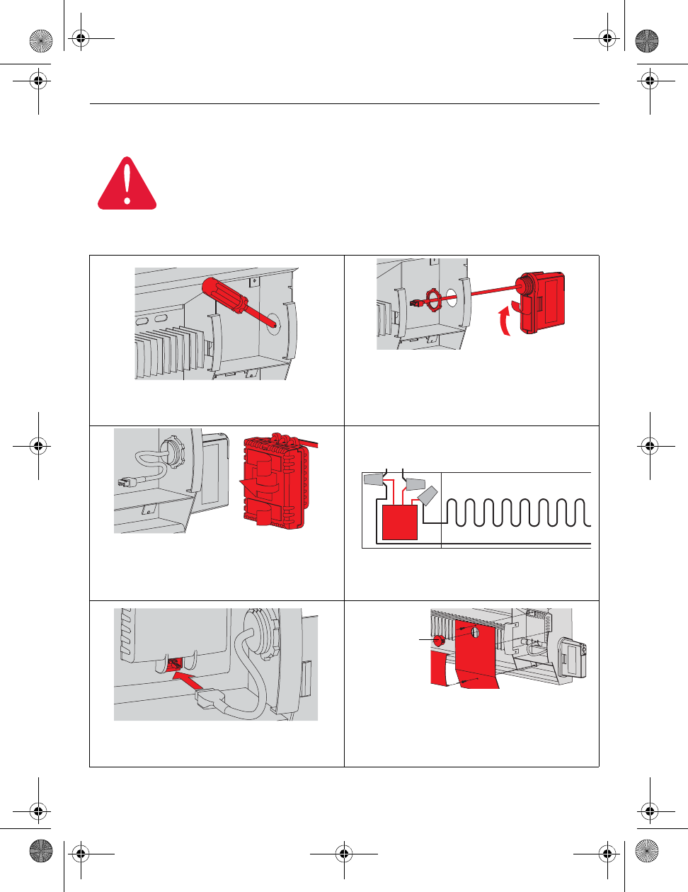
Installation in the heater
NOTE: First, disconnect the heater wires from the supply wires. If the heater has a built-in
thermostat, remove it.
ELECTRICAL HAZARD
Can cause electrical shock or equipment damage. Disconnect AC power
before beginning installation.
Wiring must comply with local electrical codes. Use special CO/ALR solderless
connectors if supply wires are made of aluminum.
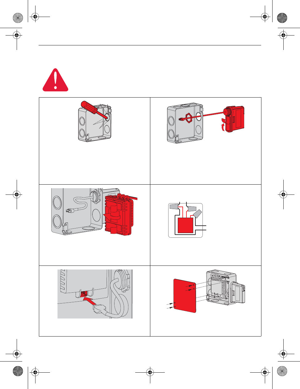
1) Remove the knockout on the side of the
heater.
2) Remove the locknut from the antenna and
peel off the adhesive backing. Feed the
antenna wires through the knockout and
install the antenna vertically as shown.
Put the locknut and tighten.
3) Peel off the adhesive backing of the relay
and stick the relay on the back panel
inside the wiring compartment with the
relay wires directed upwards.
4) Connect the heater wires and the supply
wires to the relay wires as shown.
5) Insert the antenna plug into the relay
receptacle until you hear a click.
6) Put the heater cover back. (If a built-in
thermostat was removed, install one of
the supplied plugs to cover the hole on the
existing cover.) Apply power to the heater.
Do not install the antenna cover yet.
L2 L1 : For 240V application
N L : For 120V application
BlueBlue
BlackBlack
RedRed
Install plug if
applicable.
69-2474EFS (Honeywell YTL9160 System Installation Guide).book Page 4 Friday, April 29, 2011 12:04 PM
TL9160
5
Installation in a 4”x4” junction box
ELECTRICAL HAZARD
Can cause electrical shock or equipment damage. Disconnect AC power
before beginning installation.
Wiring must comply with local electrical codes. Use special CO/ALR solderless
connectors if the supply wires are made of aluminum.
1) Mount the junction box on the wall. Punch
out a knockout on the side of the electrical
box where the AC wires come in. Punch
out another one or two knockouts for the
heater and supply wires. Install strain
relief bushings.
2) Remove the locknut from the antenna and
peel off the adhesive backing. Feed the
antenna wires through a knockout and
mount the antenna vertically as shown.
Put the locknut and tighten.
3) Peel off the adhesive backing of the relay
module and stick the relay inside the
electrical box with the relay wires directed
upwards (as shown).
4) Feed the supply wires and heater wires
through a knockout and connect them to
the relay module.
5) Insert the antenna plug in the relay
receptacle until you hear a click.
6) Install a cover plate and apply power to
the heater. Do not put the antenna
cover back yet.
To heater
L2 L1 : For 240V application
N L : For 120V application
Blue
Blue
Black
Black
Red
Red
69-2474EFS (Honeywell YTL9160 System Installation Guide).book Page 5 Friday, April 29, 2011 12:04 PM
Installation Guide
6
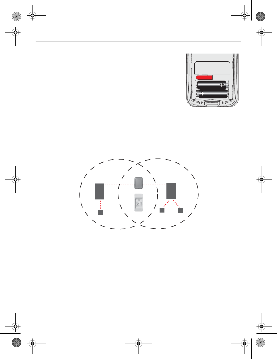
Start wireless setup
Press the CONNECT button on the antenna to place it in wireless setup. When the amber
light changes to a green flashing light, you can begin to link devices to the wireless network
(see pages 7-10).
NOTE 1: If the amber light changes to a red
light instead, there is another EIM currently in
wireless setup. Press the CONNECT button on
the other EIM to exit its wireless setup.
NOTE 2: If the green flashing light disappears
(after a delay of 15 minutes) before you have
time to link all your devices, press the
CONNECT button again.
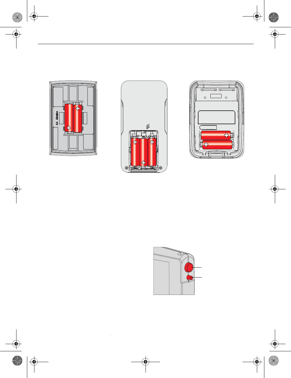
Install batteries in wireless devices
3.
Thermostat Remote control Outdoor air sensor
Install 2 AA alkaline batteries Install 3 AA alkaline batteries Install 2 AA lithium batteries
Link all devices to wireless network
4.
Press and release
* Flashing green: Ready for connection
Steady green: Connection established
Steady red: Connection failure
LED *
69-2474EFS (Honeywell YTL9160 System Installation Guide).book Page 6 Friday, April 29, 2011 12:04 PM
TL9160
7
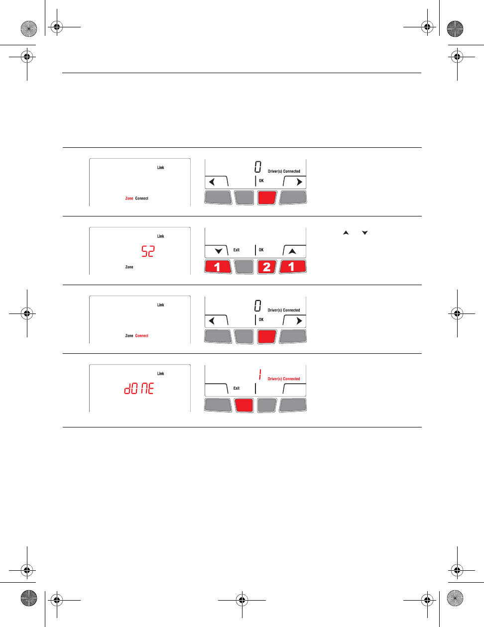
Link thermostat and EIM to wireless network
Perform the following steps on the thermostat:
NOTE: You can skip step 2 if you do not have a wireless remote control or do not have
more than one wireless thermostat in your house.
# Display Button Step
1) The Link menu appears
when you connect the
thermostat to wireless
network for the first time.
Press OK to select Zone.
2) Press or to change
the zone name (see page
15) and press OK.
3) Press OK to select
Connect.
4) DONE confirms the
connection is successful.
Press Exit once to link
another EIM (see page 8)
or 3 times to return to
home screen.
69-2474EFS (Honeywell YTL9160 System Installation Guide).book Page 7 Friday, April 29, 2011 12:04 PM
Installation Guide
8
Link additional EIM to wireless network (if applicable)
NOTE: Perform steps 1 to 6 for each additional EIM. You can link a maximum of 8 EIMs to
the wireless neywork.
1) If the green light on the EIM that was last linked is still flashing, press its CONNECT
button. The green light will become steady.
2) Press the CONNECT button on the next EIM you wish to link and wait for its green
flashing light.
NOTE: Skip steps 3 and 4 if the Link menu is still displayed on the thermostat (as
shown in step 5).
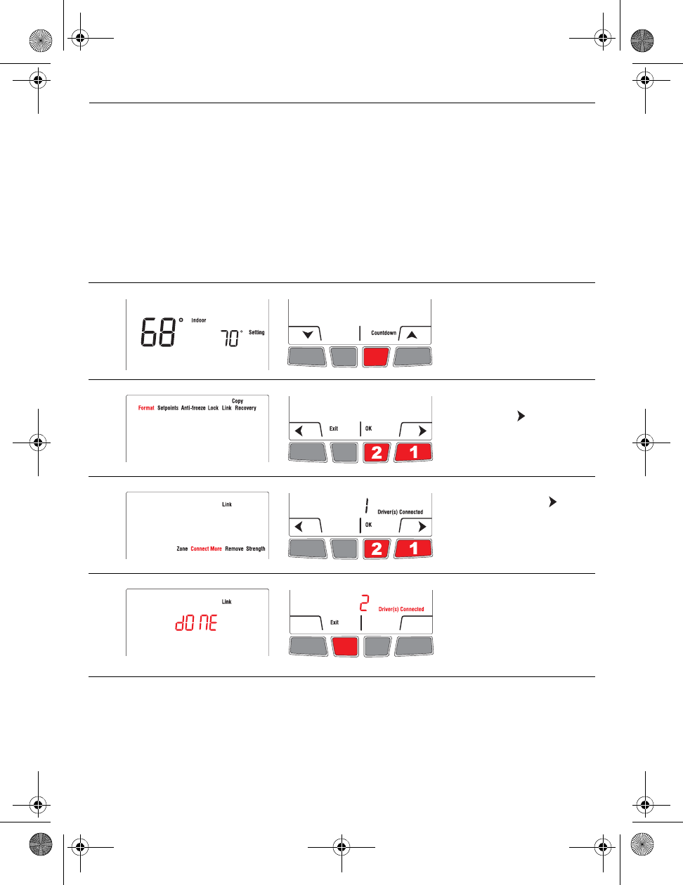
# Display Button Step
3) Press and hold the right
center button for 5 secs.
4) From the installer’s setup
menu, press to select
Link and press OK.
5)
If necessary, press to
select Connect More and
press OK.
6) DONE appears to confirm
the connection is
successful. Press Exit and
go back to step 1 once to
link another EIM or 3 times
to return to home screen.
69-2474EFS (Honeywell YTL9160 System Installation Guide).book Page 8 Friday, April 29, 2011 12:04 PM
TL9160
9
Link outdoor sensor to wireless network (if applicable)
1) Make sure the green light on the EIM is flashing;
this indicates the wireless setup is still active. If
not, activate the wireless setup (see page 6).
NOTE: If you have more than one wireless
thermostat, make sure to activate the wireless
setup from an EIM connected to the same
network as the thermostat. For example, to
display the outdoor temperature on thermostat Y,
you can activate the wireless setup from either
EIM B or C, not A.
2) Press the CONNECT button on the back of the sensor.
3) After 15 seconds, check if the thermostat is displaying a value for the outdoor
temperature reading.
NOTE: If you have more than one wireless thermostat, repeat steps 1 and 3 for each
thermostat.
Link remote control to wireless network (if applicable)
1) Make sure the green light on the EIM is flashing, which indicates the wireless setup is
still active. If not, activate the wireless setup (see page 6).
NOTE: If you have more than one wireless thermostat, make sure to activate the
wireless setup from an EIM connected to the same network as the thermostat. For
example, to link the remote control to thermostat Y, you can activate the wireless setup
from either EIM B or C, not A.
2) Refer to the remote control guide for connection to the wireless network.
Press and
release
Remote
control
Thermostat X Thermostat Y
EIM A EIM B EIM C
Outdoor
sensor
Bathroom
wireless network
Bedroom
wireless network
69-2474EFS (Honeywell YTL9160 System Installation Guide).book Page 9 Friday, April 29, 2011 12:04 PM
Installation Guide
10
1) Press the CONNECT button at the EIM. The green flashing light on the antenna will
change to a steady green light.
NOTE: If you do not press the CONNECT button, the EIM will automatically exit wireless
setup after 15 minutes of inactivity.
2) Put the cover back on the antenna module.
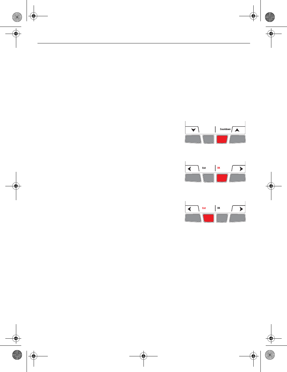
Hidden installer’s setup menu button
• To display the installer’s setup menu from the home
screen, press and hold the right center button for 5
secs.
OK button
• Press OK to accept the setting on the screen and move
to the next parameter or menu.
NOTE: Pressing OK saves the new setting or confirms
you accept the current setting.
Exit button
• Press Exit to return to the previous menu or to the
home screen.
NOTE: If you press Exit right after changing a setting,
the new setting will not be saved. Make sure you press
OK to save the new setting before you press Exit.
Exit wireless setup 5.
Customize the thermostat
6.
69-2474EFS (Honeywell YTL9160 System Installation Guide).book Page 10 Friday, April 29, 2011 12:04 PM
TL9160
11
Default settings
NOTE: To set the date & time, the schedule and the automatic daylight savings, refer to User’s Guide.
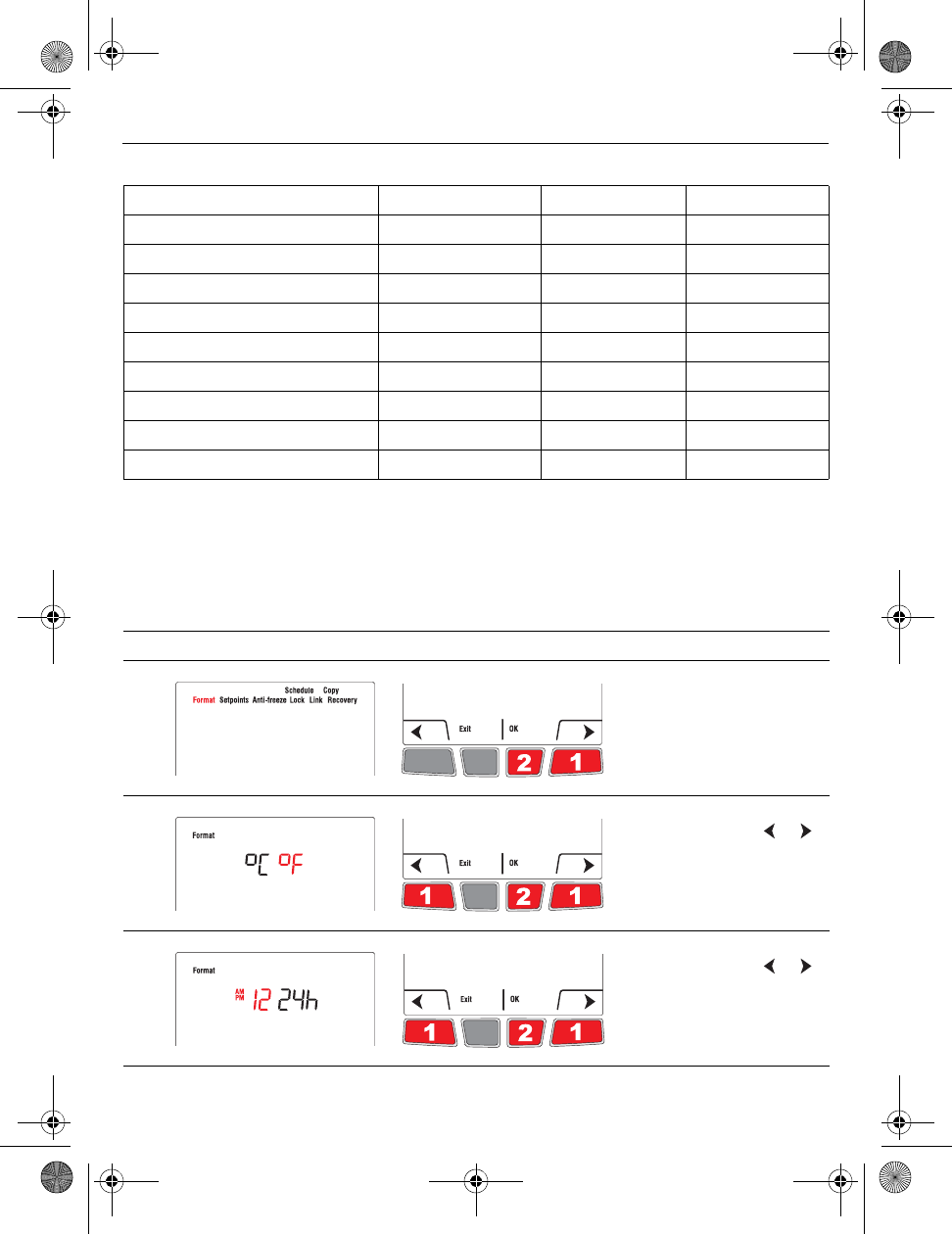
Temperature unit / Time format
Follow this procedure to select the temperature unit (°C or °F) and time format (12h or 24h).
NOTE: The time format selection is available only if the thermostat is in programmable
mode.
Parameter Choices Default setting To modify, see
Temperature unit °C / °F °F Page 11
Time format 12h / 24h 12h Page 11
Minimum setpoint 41°F (5°C) Page 12
Maximum setpoint 86°F (30°C) Page 12
Anti-freeze On / Off On Page 13
Lock None / Partial / All None Pages 13-14
Zone 1, ..., 57 52 Pages 14-15
Adaptive Intelligent Recovery On / Off On Page 16
Schedule On / Off On Page 17
# Display Button Step
1) From the installer’s setup
menu, press OK to select
the Format menu.
2)
If necessary, press or
to change the temperature
unit. Press OK.
3)
If necessary, press or
to change the time format.
Press OK.
69-2474EFS (Honeywell YTL9160 System Installation Guide).book Page 11 Friday, April 29, 2011 12:04 PM
Installation Guide
12
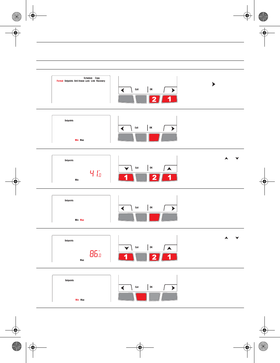
Minimum and maximum setpoints
Follow this procedure to set the minimum and maximum setpoint temperature.
# Display Button Step
1) From the installer’s setup
menu, press to select
Setpoints and press OK.
2) Press OK to select Min.
3) If necessary, press or
to change the minimum
setpoint. Press OK.
4) Press OK to select Max.
5) If necessary, press or
to change the maximum
setpoint. Press OK.
(Pressing Exit will cancel
the change.)
6) Press Exit once to return
to installer’s setup menu or
twice to return to home
screen.
69-2474EFS (Honeywell YTL9160 System Installation Guide).book Page 12 Friday, April 29, 2011 12:04 PM
TL9160
13
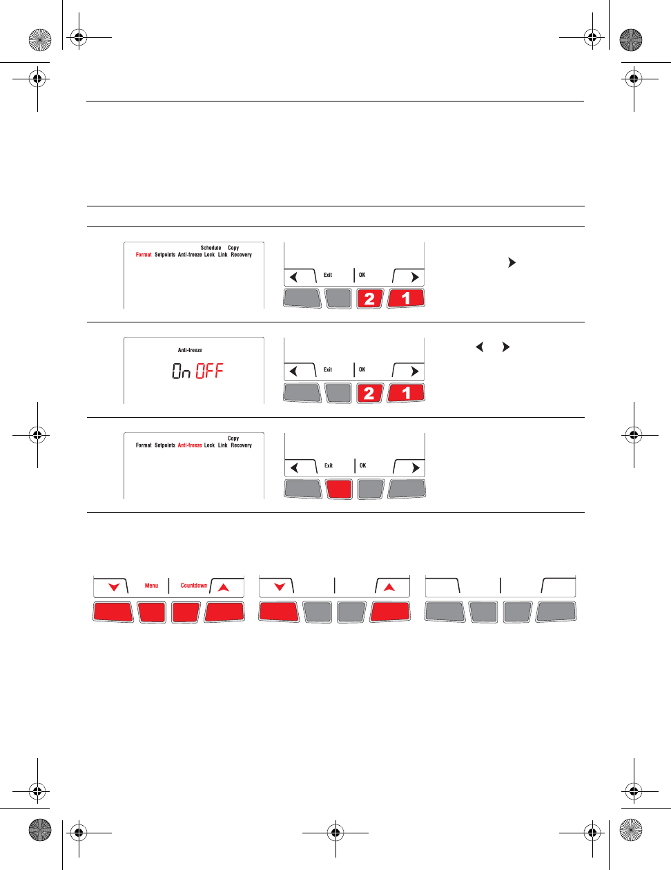
Anti-freeze
When this function is on, the EIM will maintain the room temperature at 55°F (13°C) if it
loses communication with the thermostat or if the thermostat sensor is defective. The
protection automatically turns on when the EIM is linked to the thermostat. Leave the
protection on unless the EIM is installed in a junction box in a separate room from the
heater. To turn off the protection, proceed as follows:
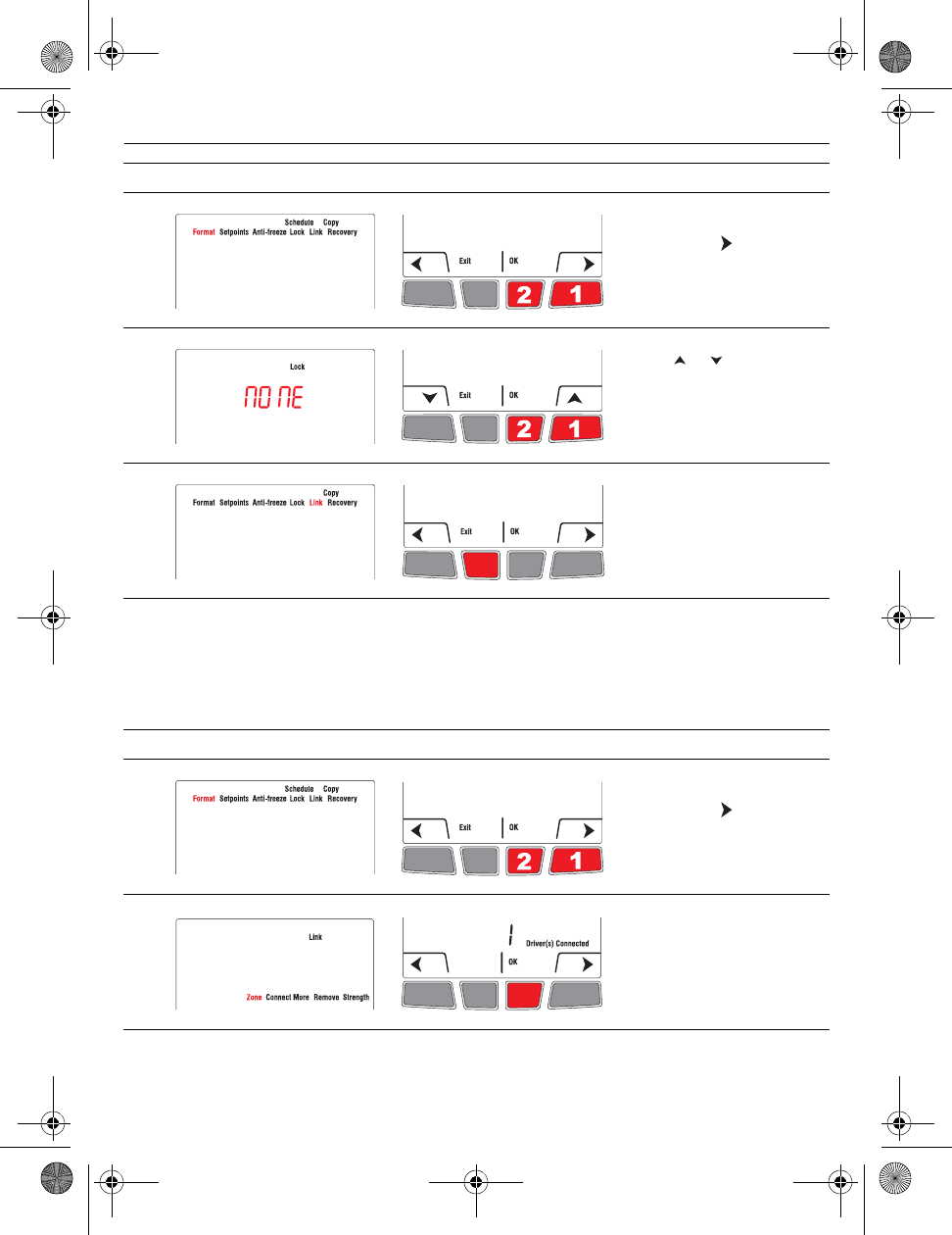
Lock
By default, the setting lock is disabled.
# Display Button Step
1) From the installer’s setup
menu, press as needed
to select Anti-Freeze and
press OK.
2)
Press or to set to
OFF. Press OK.
3) Press Exit once to return
to installer’s setup menu or
twice to return to home
screen.
If you select All, no button is
available. You cannot change
any setting except for the
installer’s setup menu.
If you select Part (Partial), you
can change the room
temperature only.
If you leave at None, you have
full access to all thermostat
settings.
69-2474EFS (Honeywell YTL9160 System Installation Guide).book Page 13 Friday, April 29, 2011 12:04 PM
Installation Guide
14
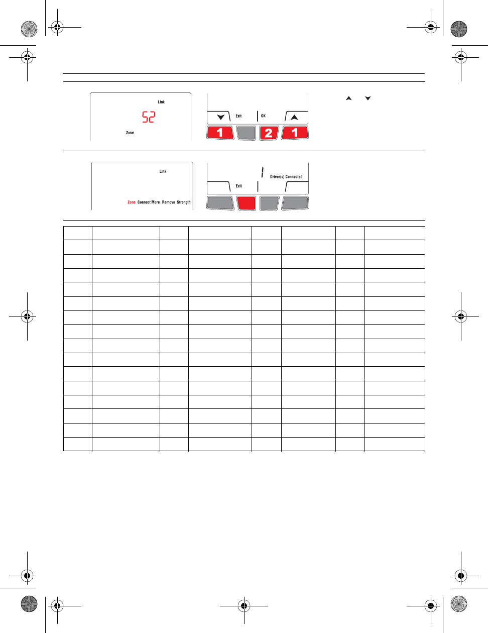
Zone
The zone name is used to identify the thermostat on the wireless remote control. By default, the
zone name of the thermostat is Thermostat (zone 52). If you have a wireless remote control and
several wireless thermostats, change the zone name of the thermostat to identify it from the
other thermostats. For example, if the thermostat is in the living room, set the zone to 31.
# Display Button Step
1) From the installer’s setup
menu, press to select
Lock and press OK.
2) Press or to select All,
Part (partial) or None.
Press OK.
3) Press Exit once to return
to installer’s setup menu or
twice to return to home
screen.
# Display Button Step
1) From the installer’s setup
menu, press to select
Link and press OK.
2) Press OK to select Zone.
69-2474EFS (Honeywell YTL9160 System Installation Guide).book Page 14 Friday, April 29, 2011 12:04 PM
TL9160
15
3) Press or to set the
value. Press OK.
4) Press Exit once to return
to installer’s setup menu or
twice to return to home
screen.
Zone Name Zone Name Zone Name Zone Name
1 Basement 16 Exercise Room 30 Library 44 Porch
2 Bathroom 17 Family Room 31 Living Room 45 Rec Room
3 Bathroom 1 18 Fireplace 32 Lower Level 46 Sewing Room
4 Bathroom 2 19 Foyer 33 Master Bath 47 Spa
5 Bathroom 3 20 Game Room 34 Master Bed 48 Storage Room
6 Bedroom 21 Garage 35 Media Room 49 Studio
7 Bedroom 1 22 Great Room 36 Music Room 50 Sun Room
8 Bedroom 2 23 Guest Room 37 Nursery 51 Theater
9 Bedroom 3 24 Gym 38 Office 52 Thermostat
10 Bedroom 4 25 Kid's Room 39 Office 1 53 Upper Level
11 Boat House 26 Kitchen 40 Office 2 54 Utility Room
12 Bonus Room 27 Kitchen 1 41 Pantry 55 Walk In Closet
13 Computer Room 28 Kitchen 2 42 Play Room 56 Wine Cellar
14 Den 29 Laundry Room 43 Pool Room 57 Workshop
15 Dining Room
69-2474EFS (Honeywell YTL9160 System Installation Guide).book Page 15 Friday, April 29, 2011 12:04 PM
Installation Guide
16
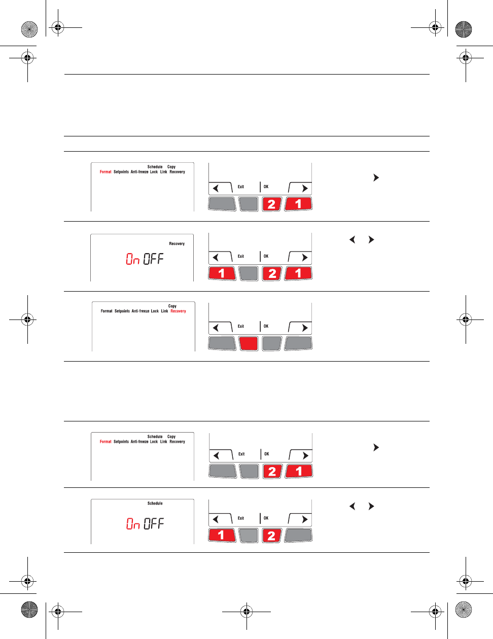
Adaptive Intelligent Recovery
Available only if you use the thermostat in programmable mode.
When Adaptive Intelligent Recovery is on, the thermostat “learns” how long your heater takes to reach the set
temperature. The thermostat will then determine when to activate heating so the desired temperature is attained at
the desired time. The thermostat re-assesses the heating start time daily based on the previous day’s performance.
When Adaptive Intelligent Recovery is off, heating starts at the set time.
Schedule
The thermostat is factory-set as a 7-day programmable thermostat. To set it as a non-programmable thermostat,
proceed as follows:
# Display Button Step
1) From the installer’s setup
menu, press to select
Recovery and press OK.
2)
Press or to select Off
and press OK.
3) Press Exit to return to
home menu.
# Display Button Step
1) From the installer’s setup
menu, press to select
Schedule and press OK.
2)
Press or to select Off
and press OK.
69-2474EFS (Honeywell YTL9160 System Installation Guide).book Page 16 Friday, April 29, 2011 12:04 PM
TL9160
17
Copy
Use this function to copy the configuration settings, the schedule settings or both to the
other wireless thermostats if you have several wireless thermostats in your house. This
function is available only if the thermostat is connected either to a remote control or to an
outdoor sensor. The parameters are copied to the other thermostats that are also
connected to the remote control or to the outdoor sensor.
System test
1) Set the temperature above the room ambient temperature.
2. Wait for Heat On to display on the thermostat.
3. Verify if the heater can become hot .
4. Press Cancel.
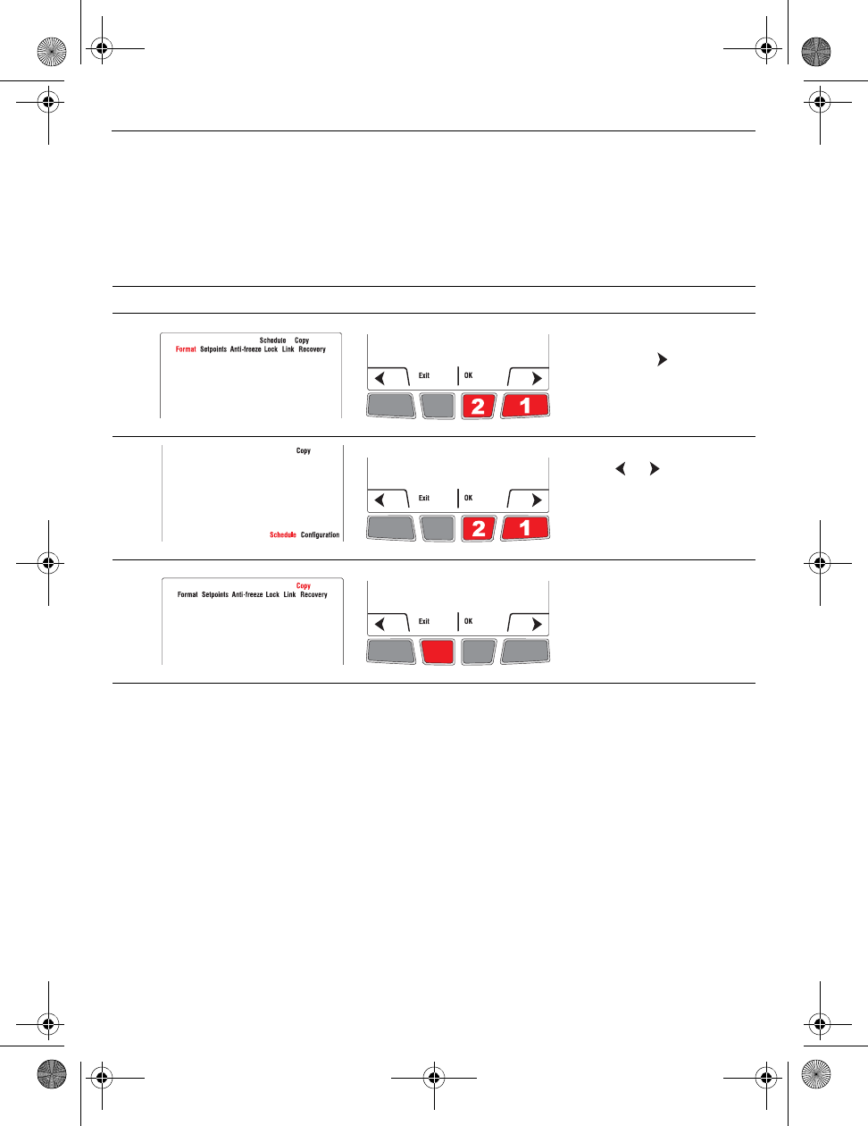
# Display Button Step
1) From the installer’s setup
menu, press as needed
to select Copy and press
OK.
2)
Press or to select
Schedule, Configuration
or both (Schedule
Configuration). Press
OK.
3) Wait may appear for
several minutes. When the
installer’s setup menu
appears, press Exit to
return to home menu.
69-2474EFS (Honeywell YTL9160 System Installation Guide).book Page 17 Friday, April 29, 2011 12:04 PM
Installation Guide
18
Follow the guidelines below when mounting the thermostat:
• Do NOT install the thermostat in an area where it can be exposed to water or rain.
• Avoid locations where there are air drafts (top of staircase, air outlet), dead air spots (behind a
door), direct sunlight or concealed chimney or stove pipes.
• For a new installation, choose a location about 1.5 m (5 ft.) above the floor.
• Install the thermostat on an inside wall facing the heater.
• Keep the thermostat's top and bottom air vents (openings) clean and unobstructed at all times.
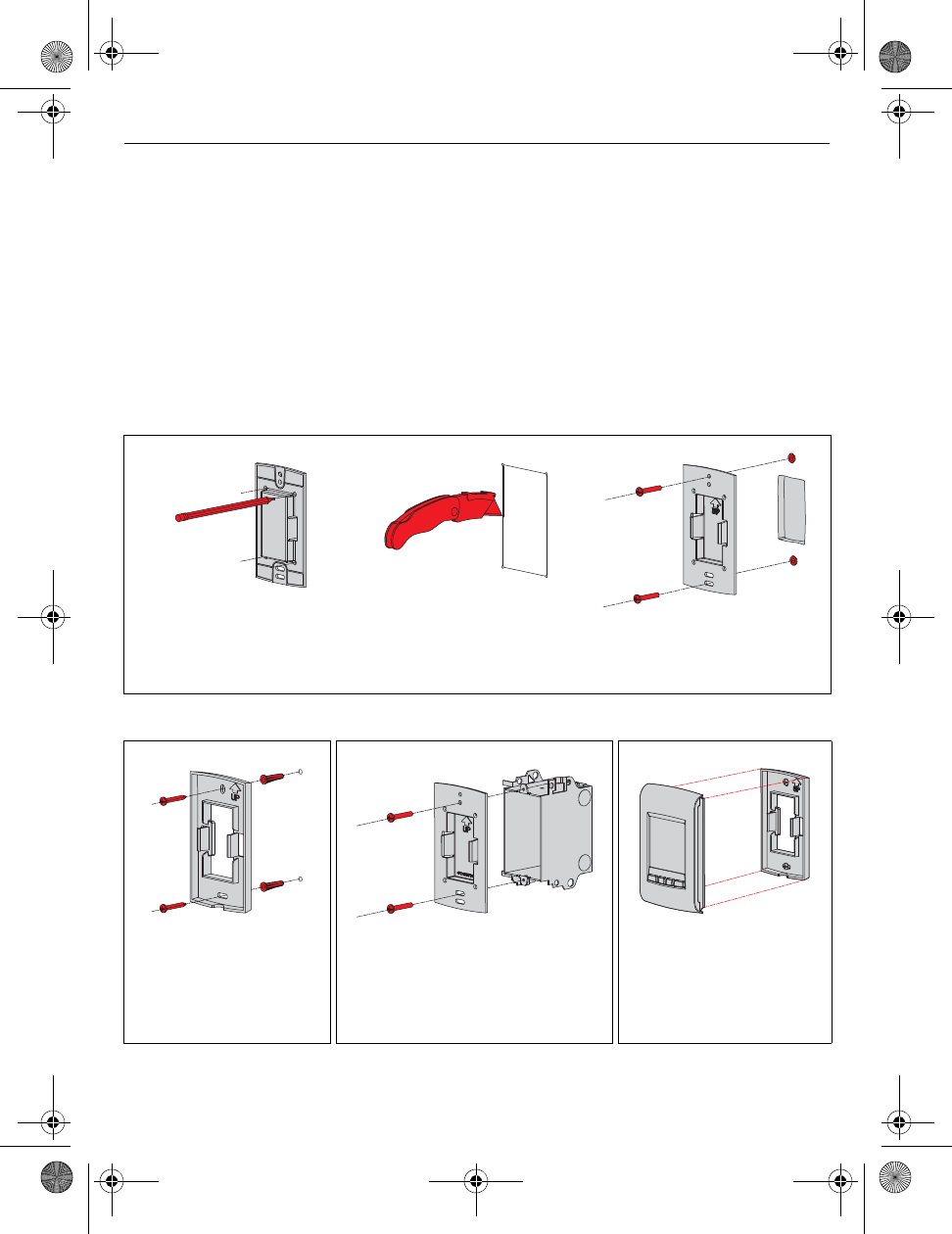
Two mounting plates are provided for mounting the thermostat on the wall or on a junction box.
Mount thermostat and outdoor sensor 7.
1) Recessed mounting on a wall
1a) Mark the four corners
and join them to create
a rectangular outline.
1b) Cut along the outline
to create an opening
in the wall.
1c) Secure the mounting plate
to the wall using provided
wall anchors and screws.
1) Mounting on a wall 1) Mounting on a junction box 2) Installing faceplate
Secure the mounting
plate to the wall using
provided wall anchors
and screws.
Secure the mounting plate to a
junction box using provided
mechanical screws. Use the
mounting plate that has no
center opening.
Complete the thermostat
installation by pressing
the faceplate against the
mounting plate.
69-2474EFS (Honeywell YTL9160 System Installation Guide).book Page 18 Friday, April 29, 2011 12:04 PM
TL9160
19
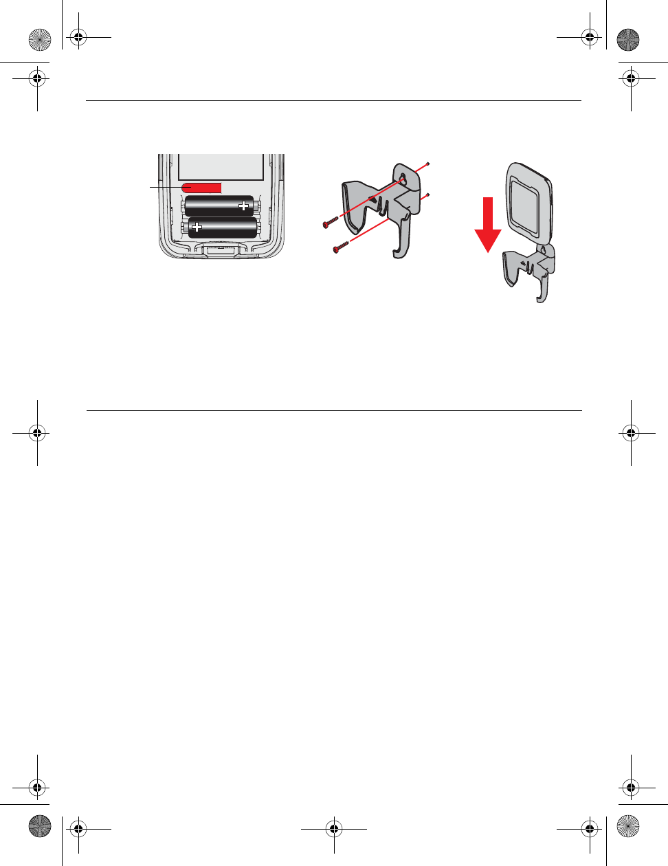
3) Install the outdoor sensor (optional)
Hold sensor where you intend to
install it and press the CONNECT
button. If sensor is communicating
with the thermostat, the latter will
display the outdoor temperature.
Mount the sensor
vertically on an
exterior wall, at least 6
inches below any
overhang. Choose a
location protected
from direct sunlight.
Place sensor securely
in bracket, facing
away from wall.
Error codes
8.
Display Description
LO The indoor temperature is below 0°C (32°F).
HI The indoor temperature is above 60°C (140°F).
- - The temperature reading is currently unavailable or the sensor is defective.
E27 If the error does not clear after 15 seconds, the thermostat is defective and must
be replaced.
E128 Call customer assistance. The wireless network setup must be redone.
E129 Attempting to connect incompatible wireless devices.
E130 Invalid address. Call customer assistance.
E134 Low signal strength. Move wireless device to a different location and try again.
E137 Maximum number of devices is exceeded.
E138 Make sure Connected light on EIM is flashing and you are 2+ feet away from EIM.
E152 Incorrect order
Press and
release
69-2474EFS (Honeywell YTL9160 System Installation Guide).book Page 19 Friday, April 29, 2011 12:04 PM
Installation Guide
20
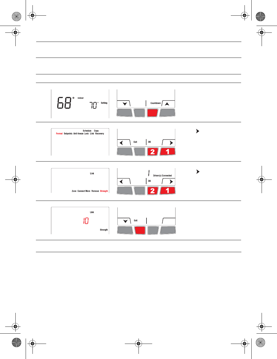
NOTE: If you have several EIMs linked to the thermostat, the displayed value is between the
thermostat and the first linked EIM. The signal strength ranges from 0 (no signal) to 10 (strongest).
Thermostat
To replace the thermostat, install batteries in the new thermostat (see page 6) and link it to the wireless
network (see page 6). To customize the thermostat, see page 10.
NOTE: If you have more than one EIM in the wireless network, you can link the thermostat from any of
the EIMs.
Remote control or outdoor sensor
To replace the remote control or the outdoor sensor, install batteries in the new device (see page 6)
and link it to the wireless network (see page 9).
Verifying the signal strength between the EIM and the thermostat
9.
# Display Button Step
1)
From the home screen,
press and hold the right
center button for 5 secs.
2) Press to select Link and
press OK.
3)
Press to select
Strength and press OK.
5) The signal strength is
displayed. Press Exit once
to return to installer’s setup
menu or twice to return to
home screen.
Replacing wireless devices
10.
69-2474EFS (Honeywell YTL9160 System Installation Guide).book Page 20 Friday, April 29, 2011 12:04 PM
TL9160
21
NOTE 1: If you have more than one EIM in the wireless network, you can link the wireless device from
any of the EIMs.
NOTE 2: If you have more than one wireless thermostat, link the remote control or the outdoor sensor
to the wireless network of each wireless thermostat.
Equipment interface module (EIM)
To replace an EIM, undo the current network and create a new one as follows:
NOTE: Skip steps 1 and 2 if you have only one EIM in the wireless network.
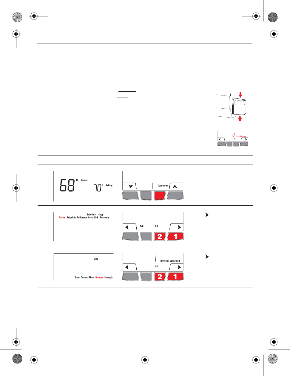
1) Remove the antenna cover from each EIM in the network: place one finger
on the top and another finger on the bottom (as shown by red arrows),
squeeze the cover and pull it out.
2) Press, for 10 seconds, the CONNECT button on any EIM that has a green
light. Repeat this step until the green light on every EIM in the network is
off.
3) If the thermostat displays 0 device connected as shown on the right, go
to step 7. Otherwise proceed with steps 4 to 6.
7) If you have a remote control, remove its link from the wireless network. (This will also remove the
remote control link to any other wireless network.)
8) Remove the defective EIM and install a new one (see pages 3 - 5).
9) Create a wireless network and link all wireless devices (EIM, thermostat, outdoor sensor and
remote control). See pages 6 to 10.
# Display Button Step
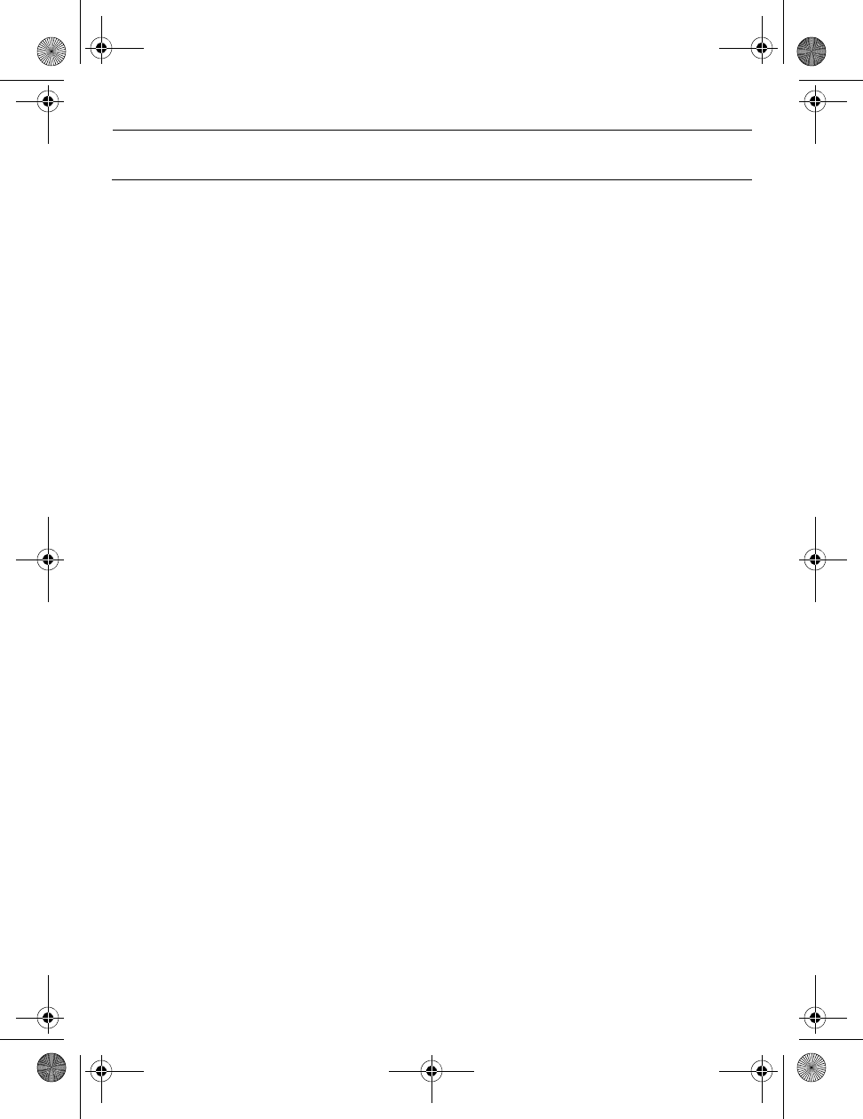
4) From the home screen,
press and hold the right
center button for 5 secs.
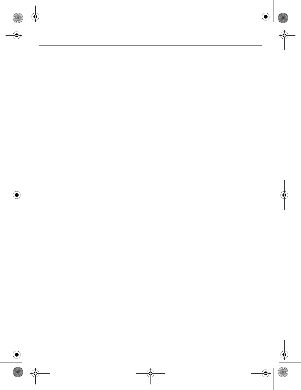
5) Press to select Link and
press OK.
6) Press to select Remove
and press OK. The
thermostat will display 0
device connected.
69-2474EFS (Honeywell YTL9160 System Installation Guide).book Page 21 Friday, April 29, 2011 12:04 PM
Installation Guide
22
Thermostat
Temperature setpoint range: 41°F - 86°F (5°C - 30°C)
Temperature setpoint resolution: 1°F (0.5°C)
Temperature display range: 32°F - 104°F (0°C - 40°C)
Temperature display resolution: 1°F/ 0.5°C standard
Heating cycle rate: 15 minutes
Programming: 5-2 days, 7 days, 1 day or Non-Programmable
Operating Ambient Temperature
Thermostat: 32°F - 122°F (0°C - 50°C)
Remote control: 32°F - 120°F (0°C - 48.9°C)
EIM (relay): -4°F - 158°F (-20°C - 70°C)
EIM (antenna): -4°F - 158°F (-20°C - 70°C)
Outdoor air sensor: -40°F - 140°F (-40°C - 60°C)
Operating Relative Humidity
Thermostat: 5% - 90% (non-condensing)
Remote control: 5% - 90% (non-condensing)
EIM (relay): 5% - 95% (non-condensing)
EIM (antenna): 5% - 95% (non-condensing)
Outdoor air sensor: 0% - 100% (condensing)
Physical Dimensions (height, width, depth)
Thermostat: 5.13 x 3.22 x 1.14 inches (130 x 82 x 29 mm)
EIM (relay): 3.03 x 2.49 x 1.28 inches (73 x 63 x 29 mm)
EIM (antenna): 2.89 x 2.63 x 1.16 inches (71 x 62 x 33 mm)
Outdoor air sensor: 5.00 x 3.50 x 1.68 inches (127 x 89 x 43 mm)
Electrical Ratings (EIM)
Supply: 120/208/240 VAC, 50/60 Hz
Minimum load: 0.4 A (resistive only)
Maximum load: 12.5 A (resistive only)
Accessories & Replacement Parts
Item Part Number
Equipment Interface Module (EIM) TLM1110R1000
Remote control REM5000R1001
Outdoor air sensor C7089R1013
Antenna cover (white) 50055751-002
Antenna cover (almond) 50055751-004
Specifications & replacement parts
11.
69-2474EFS (Honeywell YTL9160 System Installation Guide).book Page 22 Friday, April 29, 2011 12:04 PM
TL9160
23
Regulatory information
FCC Compliance Statement (Part 15.19) (USA only)
This device complies with Part 15 of the FCC Rules. Operation is subject to the following two conditions:
1) This device may not cause harmful interference, and
2) This device must accept any interference received, including interference that may cause undesired
operation.
FCC Warning (Part 15.21) (USA only)
Changes or modifications not expressly approved by the party responsible for compliance could void the
user’s authority to operate the equipment.
FCC Interference Statement (Part 15.105 (b)) (USA only)
This equipment has been tested and found to comply with the limits for a Class B digital device, pursuant to
Part 15 of the FCC Rules. These limits are designed to provide reasonable protection against harmful
interference in a residential installation. This equipment generates uses and can radiate radio frequency
energy and, if not installed and used in accordance with the instructions, may cause harmful interference to
radio communications. However, there is no guarantee that interference will not occur in a particular
installation. If this equipment does cause harmful interference to radio or television reception, which can be
determined by turning the equipment off and on, the user is encouraged to try to correct the interference by
one of the following measures:
• Reorient or relocate the receiving antenna.
• Increase the separation between the equipment and receiver.
• Connect the equipment into an outlet on a circuit different from that to which the receiver is connected.
• Consult the dealer or an experienced radio/TV technician for help.
EIM, thermostats and outdoor sensor
To comply with FCC and Industry Canada RF exposure limits for general population/ uncontrolled exposure,
the antenna(s) used for these transmitters must be installed to provide a separation distance of at least 20 cm
from all persons and must not be co-located or operating in conjunction with any other antenna or transmitter.
Remote control
This portable transmitter with its antenna complies with FCC and Industry Canada RF exposure limits for
general population/uncontrolled exposure. This device must not be co-located or operating in conjunction with
any other antenna or transmitter.
Section 7.1.3 of RSS-GEN
Operation is subject to the following two conditions:
1) This device may not cause interference, and
2) This device must accept any interference, including interference that may cause undesired operation of
the device.
Section 7.1.2 of RSS-GEN
Under Industry Canada regulations, this radio transmitter may only operate using an antenna of type and
maximum (or lesser) gain approved for the transmitter by Industry Canada. To reduce potential radio
interference to other users, the antenna type and its gain should be so chosen that the equivalent isotropically
radiated power (EIRP) is not more than that necessary for successful communication.
69-2474EFS (Honeywell YTL9160 System Installation Guide).book Page 23 Friday, April 29, 2011 12:04 PM
69-2474EFS (Honeywell YTL9160 System Installation Guide).book Page 24 Friday, April 29, 2011 12:04 PM