Ademco 8DL3250 Security System Receiver User Manual K0982 ii
Honeywell International Inc. Security System Receiver K0982 ii
UserManual.wiki
>
Ademco
>
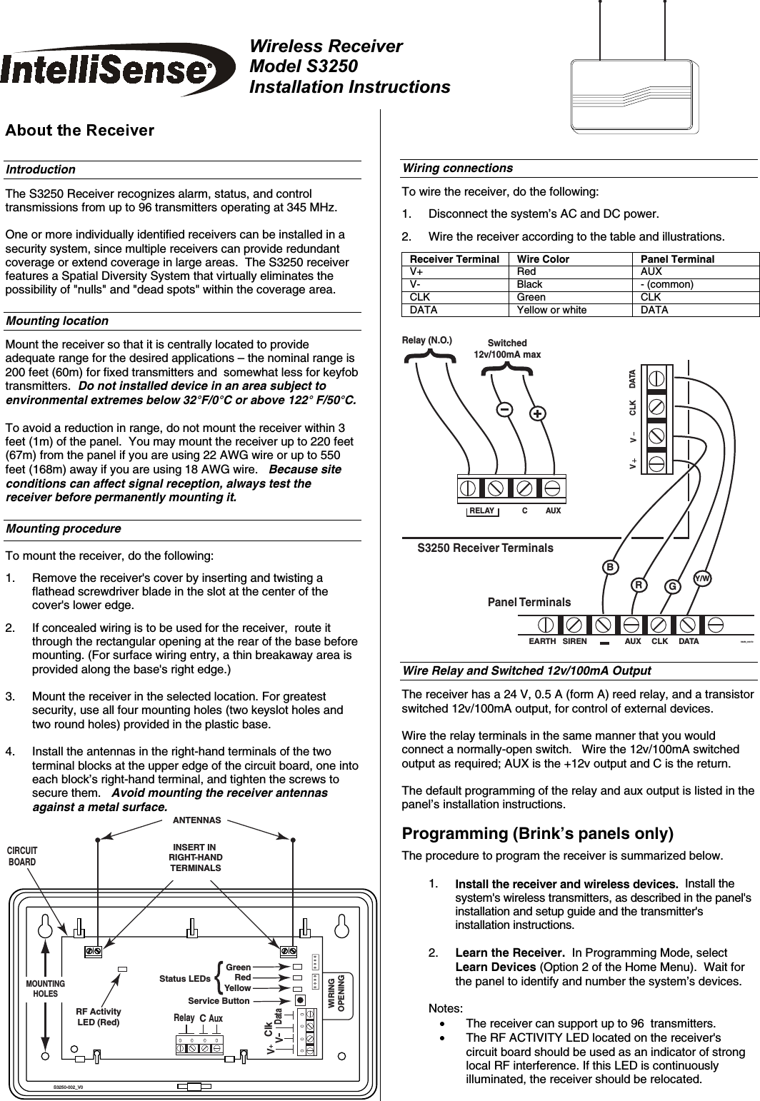
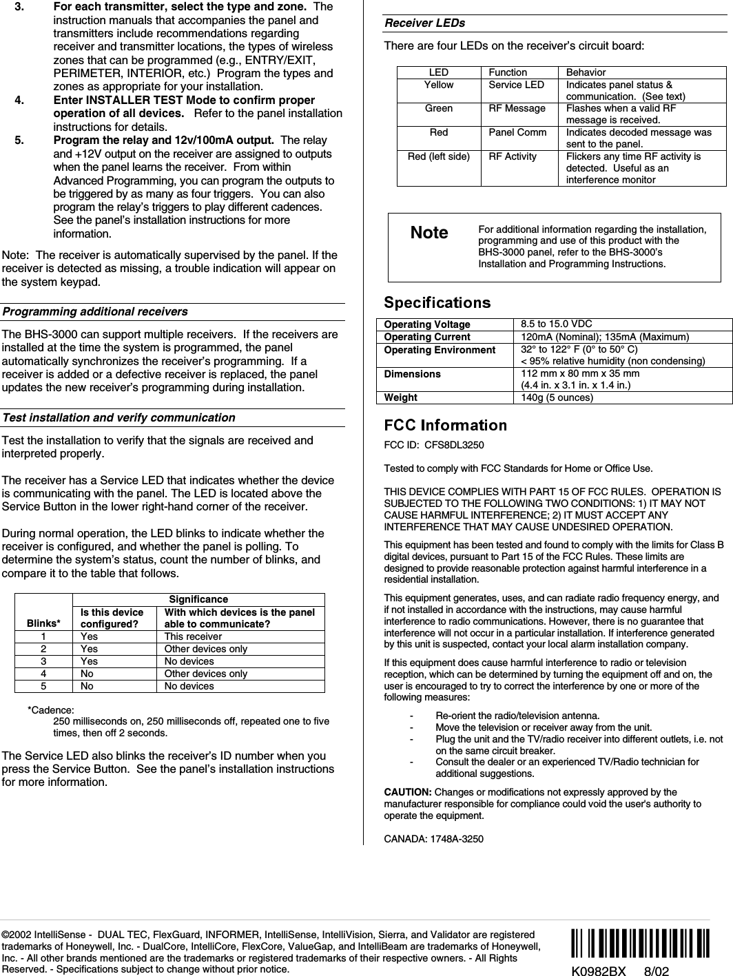
8DL3250 User Manual
II with FCC PT 15 STATEMENT
Navigation menu
Upload a User Manual
Namespaces
Wiki Guide
HTML
PDF
Info
Views
User Manual
Discussion / Help
Navigation