Ademco 8DL3250 Security System Receiver User Manual K0982 ii
Honeywell International Inc. Security System Receiver K0982 ii
Ademco >
II with FCC PT 15 STATEMENT
:LUHOHVV5HFHLYHU
0RGHO6
,QVWDOODWLRQ,QVWUXFWLRQV
Introduction
The S3250 Receiver recognizes alarm, status, and control
transmissions from up to 96 transmitters operating at 345 MHz.
One or more individually identified receivers can be installed in a
security system, since multiple receivers can provide redundant
coverage or extend coverage in large areas. The S3250 receiver
features a Spatial Diversity System that virtually eliminates the
possibility of "nulls" and "dead spots" within the coverage area.
Mounting location
Mount the receiver so that it is centrally located to provide
adequate range for the desired applications – the nominal range is
200 feet (60m) for fixed transmitters and somewhat less for keyfob
transmitters.
Do not installed device in an area subject to
environmental extremes below 32°F/0°C or above 122° F/50°C.
To avoid a reduction in range, do not mount the receiver within 3
feet (1m) of the panel. You may mount the receiver up to 220 feet
(67m) from the panel if you are using 22 AWG wire or up to 550
feet (168m) away if you are using 18 AWG wire.
Because site
conditions can affect signal reception, always test the
receiver before permanently mounting it.
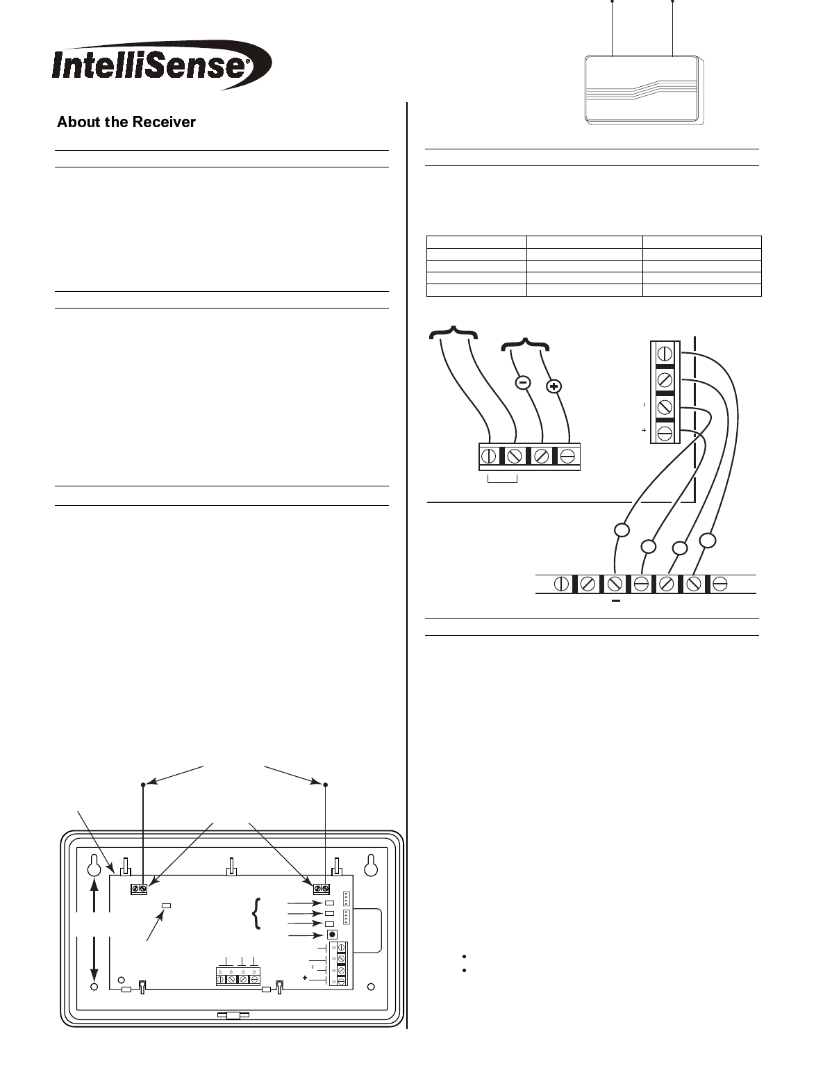
Mounting procedure
To mount the receiver, do the following:
1. Remove the receiver's cover by inserting and twisting a
flathead screwdriver blade in the slot at the center of the
cover's lower edge.
2. If concealed wiring is to be used for the receiver, route it
through the rectangular opening at the rear of the base before
mounting. (For surface wiring entry, a thin breakaway area is
provided along the base's right edge.)
3. Mount the receiver in the selected location. For greatest
security, use all four mounting holes (two keyslot holes and
two round holes) provided in the plastic base.
4. Install the antennas in the right-hand terminals of the two
terminal blocks at the upper edge of the circuit board, one into
each block’s right-hand terminal, and tighten the screws to
secure them.
Avoid mounting the receiver antennas
against a metal surface.
ANTENNAS
WIRING
OPENING
S3250-002_V0
Green
Red
Yellow
Service Button
Relay
C
Aux
Clk
V
Data
V
INSERT IN
RIGHT-HAND
TERMINALS
Status LEDs
MOUNTING
HOLES
CIRCUIT
BOARD
RF Activity
LED (Red)
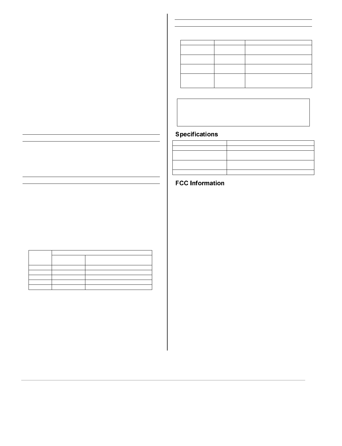
Wiring connections
To wire the receiver, do the following:
1. Disconnect the system’s AC and DC power.
2. Wire the receiver according to the table and illustrations.
Receiver Terminal Wire Color Panel Terminal
V+ Red AUX
V- Black - (common)
CLK Green CLK
DATA Yellow or white DATA
CLK DATA
RELAY C AUX
V
V
DATA
AUX CLKSIRENEARTH
Panel Terminals
S3250 Receiver Terminals
Relay (N.O.) Switched
12v/100mA max
RY/W
B
G
S3250_003-V0
Wire Relay and Switched 12v/100mA Output
The receiver has a 24 V, 0.5 A (form A) reed relay, and a transistor
switched 12v/100mA output, for control of external devices.
Wire the relay terminals in the same manner that you would
connect a normally-open switch. Wire the 12v/100mA switched
output as required; AUX is the +12v output and C is the return.
The default programming of the relay and aux output is listed in the
panel’s installation instructions.
Programming (Brink’s panels only)
The procedure to program the receiver is summarized below.
1. Install the receiver and wireless devices. Install the
system's wireless transmitters, as described in the panel's
installation and setup guide and the transmitter's
installation instructions.
2. Learn the Receiver. In Programming Mode, select
Learn Devices (Option 2 of the Home Menu). Wait for
the panel to identify and number the system’s devices.
Notes:
The receiver can support up to 96 transmitters.
The RF ACTIVITY LED located on the receiver's
circuit board should be used as an indicator of strong
local RF interference. If this LED is continuously
illuminated, the receiver should be relocated.
3. For each transmitter, select the type and zone. The
instruction manuals that accompanies the panel and
transmitters include recommendations regarding
receiver and transmitter locations, the types of wireless
zones that can be programmed (e.g., ENTRY/EXIT,
PERIMETER, INTERIOR, etc.) Program the types and
zones as appropriate for your installation.
4. Enter INSTALLER TEST Mode to confirm proper
operation of all devices. Refer to the panel installation
instructions for details.
5. Program the relay and 12v/100mA output. The relay
and +12V output on the receiver are assigned to outputs
when the panel learns the receiver. From within
Advanced Programming, you can program the outputs to
be triggered by as many as four triggers. You can also
program the relay’s triggers to play different cadences.
See the panel’s installation instructions for more
information.
Note: The receiver is automatically supervised by the panel. If the
receiver is detected as missing, a trouble indication will appear on
the system keypad.
Programming additional receivers
The BHS-3000 can support multiple receivers. If the receivers are
installed at the time the system is programmed, the panel
automatically synchronizes the receiver’s programming. If a
receiver is added or a defective receiver is replaced, the panel
updates the new receiver’s programming during installation.
Test installation and verify communication
Test the installation to verify that the signals are received and
interpreted properly.
The receiver has a Service LED that indicates whether the device
is communicating with the panel. The LED is located above the
Service Button in the lower right-hand corner of the receiver.
During normal operation, the LED blinks to indicate whether the
receiver is configured, and whether the panel is polling. To
determine the system’s status, count the number of blinks, and
compare it to the table that follows.
Significance
Blinks*
Is this device
configured?
With which devices is the panel
able to communicate?
1 Yes This receiver
2 Yes Other devices only
3 Yes No devices
4 No Other devices only
5 No No devices
*Cadence:
250 milliseconds on, 250 milliseconds off, repeated one to five
times, then off 2 seconds.
The Service LED also blinks the receiver’s ID number when you
press the Service Button. See the panel’s installation instructions
for more information.
Receiver LEDs
There are four LEDs on the receiver’s circuit board:
LED Function Behavior
Yellow Service LED Indicates panel status &
communication. (See text)
Green RF Message Flashes when a valid RF
message is received.
Red Panel Comm Indicates decoded message was
sent to the panel.
Red (left side) RF Activity Flickers any time RF activity is
detected. Useful as an
interference monitor
Note
For additional information regarding the installation,
programming and use of this product with the
BHS-3000 panel, refer to the BHS-3000’s
Installation and Programming Instructions.
Operating Voltage 8.5 to 15.0 VDC
Operating Current 120mA (Nominal); 135mA (Maximum)
Operating Environment 32° to 122° F (0° to 50° C)
< 95% relative humidity (non condensing)
Dimensions 112 mm x 80 mm x 35 mm
(4.4 in. x 3.1 in. x 1.4 in.)
Weight 140g (5 ounces)
FCC ID: CFS8DL3250
Tested to comply with FCC Standards for Home or Office Use.
THIS DEVICE COMPLIES WITH PART 15 OF FCC RULES. OPERATION IS
SUBJECTED TO THE FOLLOWING TWO CONDITIONS: 1) IT MAY NOT
CAUSE HARMFUL INTERFERENCE; 2) IT MUST ACCEPT ANY
INTERFERENCE THAT MAY CAUSE UNDESIRED OPERATION.
This equipment has been tested and found to comply with the limits for Class B
digital devices, pursuant to Part 15 of the FCC Rules. These limits are
designed to provide reasonable protection against harmful interference in a
residential installation.
This equipment generates, uses, and can radiate radio frequency energy, and
if not installed in accordance with the instructions, may cause harmful
interference to radio communications. However, there is no guarantee that
interference will not occur in a particular installation. If interference generated
by this unit is suspected, contact your local alarm installation company.
If this equipment does cause harmful interference to radio or television
reception, which can be determined by turning the equipment off and on, the
user is encouraged to try to correct the interference by one or more of the
following measures:
- Re-orient the radio/television antenna.
- Move the television or receiver away from the unit.
- Plug the unit and the TV/radio receiver into different outlets, i.e. not
on the same circuit breaker.
- Consult the dealer or an experienced TV/Radio technician for
additional suggestions.
CAUTION: Changes or modifications not expressly approved by the
manufacturer responsible for compliance could void the user's authority to
operate the equipment.
CANADA: 1748A-3250
©2002 IntelliSense - DUAL TEC, FlexGuard, INFORMER, IntelliSense, IntelliVision, Sierra, and Validator are registered
trademarks of Honeywell, Inc. - DualCore, IntelliCore, FlexCore, ValueGap, and IntelliBeam are trademarks of Honeywell,
Inc. - All other brands mentioned are the trademarks or registered trademarks of their respective owners. - All Rights
Reserved. - Specifications subject to change without prior notice.
¬.l
K0982BX 8/02