Ademco 8DL5800FLOOD Wireless Water Leak Detector User Manual Users Manaul
Honeywell International Inc. Wireless Water Leak Detector Users Manaul
Ademco >
Users Manaul
5800FLOOD Flood Detector & Temperature Sensor
INSTALLATION INSTRUCTIONS Instructions d’installation
The ADEMCO 5800FLOOD Flood Detector & Temperature
Sensor is a wireless transmitter used with Honeywell’s alarm
systems that support 5800 series devices. Applications include
bathrooms, laundry rooms, boilers and basements etc.
The 5800FLOOD:
• can serve as a hot and/or cold temperature sensor via
internal thermal sensor
(sends alarm to control when temperature is lower than
45°F (Cold condition) or above 95°F, (Hot condition).
• can serve as a Water leakage or Flood Detector via built-in
metal contacts on the bottom of the unit
(sends alarm to control within approximately 40 seconds
after water has come in contact with the metal probes.)
• does not require external probes
• functions (modes) set by programming pre-defined device
loop numbers (see table 1) to separate zones in the control
panel.
• provides tamper supervision, which sends a trouble signal
to the control if the unit’s cover is removed.
INSTALLATION
Check Signal Strength: Before installing permanently,
conduct Go/No Go tests (see control's instructions) to
verify adequate signal strength from the planned location.
Adjust the device location as necessary.
Ce contact de porte / fenêtre sans fil est conçu pour être
utilisé avec les panneaux de commande Honeywell qui
supportent les dispositifs de la série 5800. Applications
include bathrooms, laundry rooms, boilers and basements etc.
The 5800FLOOD:
• can serve as a hot and/or cold temperature sensor via
internal thermal sensor
(sends alarm to control when temperature is lower than
45°F (Cold condition) or above 95°F, (Hot condition).
• can serve as a Water leakage or Flood Detector via built-in
metal contacts on the bottom of the unit
(sends alarm to control within approximately 40 seconds
after water has come in contact with the metal probes.)
• does not require external probes
• functions (modes) set by programming pre-defined device
loop numbers (see table 1) to separate zones in the control
panel.
• provides tamper supervision, which sends a trouble signal
to the control if the unit’s cover is removed.
INSTALLATION
Check Signal Strength: Before installing permanently,
conduct Go/No Go tests (see control's instructions) to
verify adequate signal strength from the planned location.
Adjust the device location as necessary.
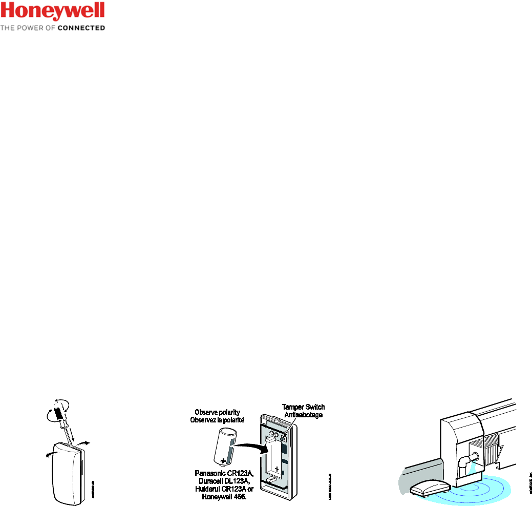
Water Leak Detection
Place the device on the floor or other desired location near any
area that
potentially can be subject to a water leak condition
(ex. floor near or inside a kitchen cabinet, near the base of a
refrigerator, in a bathroom, basement, etc.).
Make sure the metal contacts at the bottom of the enclosure
are clean and free of any
debris before positioning the unit in
place.
To ensure the unit remains in place, use the double-sided tape
to adhere unit to the floor or other surface.
IMPORTANT: After a water leak detection event, make sure the
contacts and the unit are completely dry and free of any
debris
before relocating the device.
Temperature Sensing
Mount the device low on a wall in the desired location with
double-sided adhesive
tape (supplied).
If used solely as a temperature sensor, the 5800FLOOD can
be mounted low on a wall with double-sided adhesive
tape
(supplied).

IMPORTANT:
• Do not install this device on or near metal objects, Avoid
locating the device near wiring such as AC, telephone, HVAC,
computer data cables, etc.
• Avoid mounting the detector near heat generating devices
(e.g. ovens, heat vents,
furnaces, boilers) or on a metal
cabinet.
• DO NOT remove the circuit board from the back case.
PROGRAMMING (Setting the Operating Mode)
Table 1 lists the functions of the 5800FLOOD with their
respective loop numbers.
Program each desired loop function as a separate zone in the
control panel.
1. Enter the control’s Zone Programming mode.
2. Assign a zone number for each loop used.
Loop = 1, 2, or 3 (see table for loop functions)
Zone Type = choose a zone type based on desired operation
(ex. 24-Hr. Aux, Waterflow)
Input Type = 03 (Supervised RF)
3. When prompted for the serial number, press and release
the unit’s tamper switch twice.
Alternatively, you can manually enter the sensor serial
number found on the unit’s label.
Table 1
Mode
Loop
Fault Occurs When After… Restore when … After…
Flood
Loop 3 probe contacts water 40 sec no contact with water and
contacts are dry 40 sec
Temperature
Temperature is..
Temperature is..
Cold
Loop 1 below 45°F (7C)
15 min
above 45°F (7C)
15
min
Hot
Loop 2
above 95°F (35C) below 95°F (35C)
Table 1 (French)
Mode
Loop
Fault Occurs When After… Restore when … After…
Flood
Loop 3 probe contacts water 40 sec no contact with water and
contacts are dry 40 sec
Temperature
Temperature is..
Temperature is..
Cold
Loop 1 below 45°F (7C)
15 min
above 45°F (7C)
15
min
Hot
Loop 2
above 95°F (35C) below 95°F (35C)
TESTING
1. With the control panel in Test mode, remove & replace
device cover to activate.
2. System keypad should beep and display each programmed
zone (loop).
3. Exit control’s test mode.
MAINTAINING PROPER OPERATION
To maintain the detector in proper working condition, it is
important that you observe the
following:
• Replace the battery when a low battery condition is reported.
• Make sure the unit is situated flat on the floor, or any other
surface and make sure
the contacts are not blocked by debris
or dirt as these will affect conductivity of water
in the area.
• Clean and dry the metal probes before reusing the device
following the water leak
detection.
• It is recommended to get the advice of the alarm company to
relocate the device.
TESTING
1. With the control panelin Test mode, remove & replace
device cover to activate.
2. System keypad should beep and display each programmed
zone (loop).
3. Exit control’s test mode.
MAINTAINING PROPER OPERATION
To maintain the detector in proper working condition, it is
important that you observe the
following:
• Replace the battery when a low battery condition is reported.
• Make sure the unit is situated flat on the floor, or any other
surface and make sure
the contacts are not blocked by debris
or dirt as these will affect conductivity of water
in the area.
• Clean and dry the metal probes before reusing the device
following the water leak
detection.
• It is recommended to get the advice of the alarm company to
relocate the device.
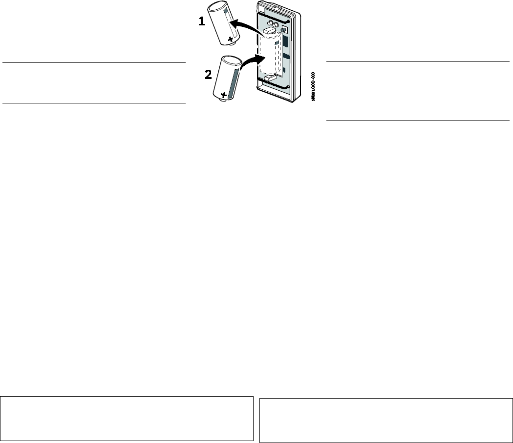
BATTERY REPLACEMENT
After removing the battery; wait at least 30
seconds before installing the new one. Use
only the following 3V Lithium batteries:
• Panasonic CR123A • Huiderui CR123A
• Duracell DL123A • Honeywell 466
CAUTION: Risk of fire, explosion, and burns. Do
not recharge, disassemble, heat above 212°F
(100°C) or incinerate. Dispose of used batteries
properly. Keep away from children.
NOTE: Constant exposure to high or low
temperature or high humidity may reduce battery
life.
BATTERY REPLACEMENT
After removing the battery; wait at least 30
seconds before installing the new one. Use
only the following 3V Lithium batteries:
• Panasonic CR123A • Huiderui CR123A
• Duracell DL123A • Honeywell 466
Attention de batterie : Risque d'incendie,
d'explosion et de brûlures. Ne rechargez pas,
démonter, chauffer au-dessus de 212° F (100°C),
ou incinérer. Débarrassez-vous des batteries
utilisées de façon appropriée. Gardez à partir des
enfants.
NOTE : Une exposition constante à des
températures élevées ou basses ou à un taux
d'humidité élevée peut réduire la durée de vie de la
pile.
SPECIFICATIONS
Battery Type 3V Lithium, CR123A
(battery life ~4-5 years)
Standby Current 3µA maximum
Consumption
Low Battery Detection 2.8V ±20mV
Unit (Battery) Shut Down 1.8V ±20mV
RF Frequency 344.94MHZ (5800 protocol)
RF Range 200ft (60m) nominal indoors from
wireless transmitters (the actual
range to be determined with the
security system in the Test mode).
Operational Temperature 14°F to 104°F (-10°C to +40°C)
Cold- Hot Alert detection < 45°F for Cold, and ≥ 95°F for Hot
(<7.2°C for Cold, and ≥ 35°C for Hot)
Water Sensing Probes Stainless steel contacts
Water Leak Detection Reports alarm within 30-40 seconds.
Dimensions 3.1” L x 1.6” W x 2.0” D max.
(7.9cm L x 4.1mm W x 5.8mm D max.)
REFER TO THE INSTALLATION INSTRUCTIONS FOR THE
CONTROL WITH WHICH THIS DEVICE IS USED, FOR
DETAILS REGARDING LIMITATIONS OF THE ENTIRE
ALARM SYSTEM.
SPECIFICATIONS
Battery Type 3V Lithium, CR123A
(battery life ~4-5 years)
Standby Current 3µA maximum
Consumption
Low Battery Detection 2.8V ±20mV
Unit (Battery) Shut Down 1.8V ±20mV
RF Frequency 344.94MHZ (5800 protocol)
RF Range 200ft (60m) nominal indoors from
wireless transmitters (the actual
range to be determined with the
security system in the Test mode).
Operational Temperature 14°F to 104°F (-10°C to +40°C)
Cold- Hot Alert detection < 45°F for Cold, and ≥ 95°F for Hot
(<7.2°C for Cold, and ≥ 35°C for Hot)
Water Sensing Probes Stainless steel contacts
Water Leak Detection Reports alarm within 30-40 seconds.
Dimensions 3.1” L x 1.6” W x 2.0” D max.
(7.9cm L x 4.1mm W x 5.8mm D max.)
POUR LES DÉTAILS CONCERNANT LES LIMITATIONS
DU SYSTÈME DANS SON ENSEMBLE, REPORTEZ-VOUS
AUX INSTRUCTIONS D’INSTALLATION DU PANNEAU DE
COMMANDE AVEC LEQUEL LE DISPOSITIF EST UTILISÉ.
FCC / IC STATEMENT
FEDERAL COMMUNICATIONS COMMISSION & INDUSTRY CANADA STATEMENTS
The user shall not make any changes or modifications to the equipment unless authorized by the Installation Instructions or User's
Manual. Unauthorized changes or modifications could void the user's authority to operate the equipment.
This device complies with Part 15 of the FCC rules and Industry Canada’s license-exempt RSSs. Operation is subject to the following
two conditions: (1) This device may not cause harmful interference, and (2) this device must accept any interference received, including
interference that may cause undesired operation.
Unauthorized changes or modifications could void the user's authority to operate the equipment.
Cet appareil est conforme à la partie 15 des règles de la FCC & et exempt de licence RSS d’Industrie Canada. Son fonctionnement est
soumis aux conditions suivantes: (1) Cet appareil ne doit pas causer d’interférences nuisibles. (2) Cet appareil doit accepter toute
interférence reçue y compris les interférences causant une réception indésirable.
Support and Warranty / Soutien et Garantie
For online support information, please go to: https://mywebtech.honeywell.com/
Pour de l’assistance en ligne, visitez : https://mywebtech.honeywell.com/
For the latest warranty information, go to: www.honeywell.com/security/hsc/resources/wa
Pour les dernières informations de garantie, s'il vous plaît aller à :
www.honeywell.com/security/hsc/resources/wa
For patent information, see www.honeywell.com/patents
Pour des informations sur les brevets, voir www.honeywell.com/patents
MyWebTech
Warranty
Garantie
Patents
Brevets
Honeywell is a registered trademark of Honeywell International Inc. All
other trademarks are the properties of their respective owners. All
rights reserved.
Honeywell des marque déposée de Honeywell International Inc. Toutes
les autres marques de commerce appartiennent à leurs propriétaires
respectifs. Tous droits réservés.
2 Corporate Center Drive, Suite 100
P.O. Box 9040, Melville, NY 11747
2017 Honeywell International Inc.
www.honeywell.com/security
Ê800-23123jŠ
800-23123 8/17 Rev A