Ademco 8DL5800PIR-OD Security Transmitter User Manual 5890 OD Wireless Outdoor Motion Sensor
Honeywell International Inc. Security Transmitter 5890 OD Wireless Outdoor Motion Sensor
Ademco >
User manual
5800-OD Wireless Outdoor Motion Sensor – Installation Instructions
GENERAL INFORMATION
The Honeywell 5800-OD Wireless Outdoor Motion Sensor
(referred to as the 5800-OD) combines the convenience of wireless
technology with a full featured outdoor PIR motion sensor. The
major features are highlighted below:
Immunity to bright light
disturbances from headlights,
sunlight, and other bright
light sources.
Very low current draw.
Discriminates both large and
small animals to reduce false
alarms.
Selectable detector
range and angle.
Battery saving circuit allows
for a 5 or 120 second period of
inactivity before being
reactivated.
Tamper detection.
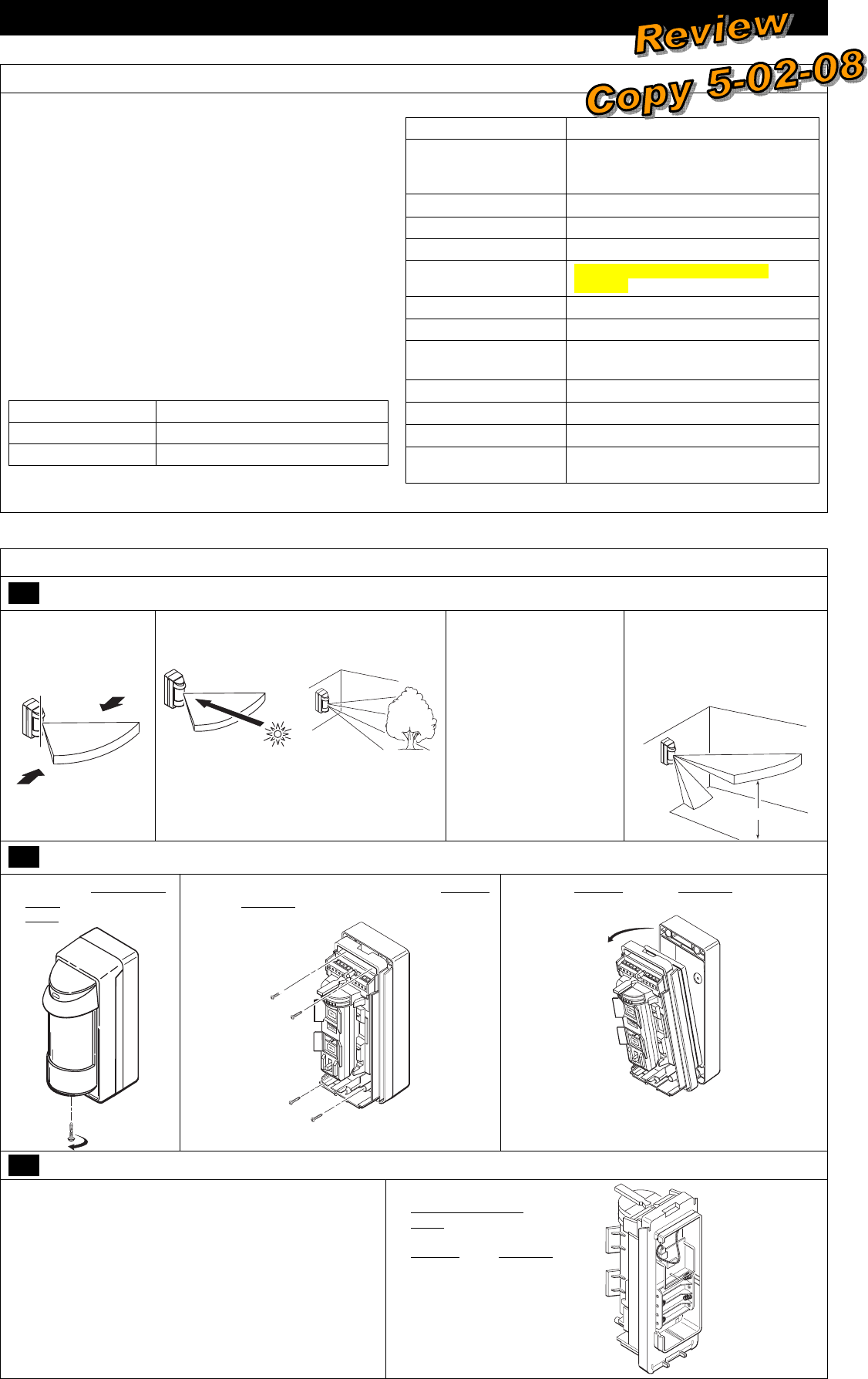
SPECIFICATIONS
Detection Method Passive Infrared
Initial Warm Up ~ 2 minutes
Mounting Height 0.8 - 1.2m (2.7 - 4ft) wall or pole
Range Adjustable up to 12m (40ft)
Pattern 90° pattern consisting of 13 zones. This
pattern can be adjusted in 15° incre-
ments from center up to 45°.
Sensitivity 2.0° C at 0.6m/s (3.6° F at 2.0ft/s)
Detection Speed 0.3 - 1.5m/s (1 - 5ft/s)
Operating Voltage 6 VDC (uses 4 lithium 1.5VDC AA cells)
Current 3mA max (during walk test) 10uA
(standby)
Battery Saving Timer Adjustable 120sec or 5sec
Alarm Period ~ 2.5 seconds
LED Indicator Enabled during a walk test.
Disabled for normal operation.
Weatherproof IP54 compliance
Operating Temperature – 20 to + 50 ° C (– 4 to +122° F)
Humidity 95% Max
Accessories (included) Pole mounting kit, screw kit, detection
masking strips.
INSTALLATION (refer to the Component Identification Diagram on page 5)
1 Select the Mounting Position
Avoid strong sunlight into the sensor's field.
Avoid moving or swaying trees and bushes.
Orient the detector
so that intrusion
passes across the
detection field, not
into the sensor.
Allow 110mm (4.4")
above the sensor to
enable opening the
cover.
Choose an installation
height of 0.8m to 1.2m
(2.7 to 4ft).
Ensure the sensor can be
mounted on a perpendicular
wall or pole that would make
its detection pattern parallel
to the ground.
Parallel
2 Prepare the Sensor for Mounting
1. Loosen the Captive Lock
Screw and remove the
Cover.
2. Remove the four (4) screws fastening the Detector
to the Back Box.
3. Remove Detector from the Back Box.
3 Install / Replace the Battery
IMPORTANT:
Use only lithium batteries.
Use four (4) lithium 1.5VDC AA cells. (Energizer L91 or
equivalent.)
Observe polarity.
Mark the date of replacement on the batteries.
1. If necessary, loosen the
Captive Lock Screw and lift
Cover off. Then, remove 4
screws that secure the
Detector to the Back Box.
2. Observe the proper polarity
and replace the batteries.
Ensure positive side of
battery is pointing away from
the springs.
3. For reference, mark the date of
replacement on the batteries.
PLEASE GO TO PAGE 6 FOR FCC / IC STATEMENTS
5800-OD Wireless Outdoor Motion Sensor – Installation Instructions
– 2 –
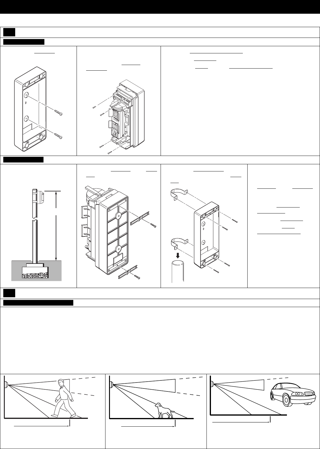
4 Mount the Sensor
WALL MOUNTING
1. Install the Back Box on the
wall with the two T4 x 20
mounting screws.
UP
2. Insert the batteries (see
Install/Replace the Battery),
then secure the Detector to the
Back Box.
3. Fasten with four (4) screws.
4. Perform Settings & Adjustments.
5. Perform a Walk Test.
6. Secure the Cover with the Captive Lock Screw.
POLE MOUNTING
1. Use a pole with an outside
diameter of 43-48mm
(1.69-1.89").
2.7- 4ft.
0.8 - 1.2m
2. Attach the Brackets to the Back
Box with two M4 x 30 screws.
3. Using the Pole Brackets and four
M4 x 30 screws, fasten the Back
Box to the pole.
UP
4. Insert the batteries (see
Install/Replace the
Battery), then mount the
Detector on the Back Box
and fasten with four (4)
screws.
5. Perform Settings &
Adjustments.
6. Perform a Walk Test.
7. Secure the Cover with the
Captive Lock Screw.
5 Perform Settings & Adjustments
SET THE DETECTION LENGTH
Note: The length of the lower detection area determines the detection length.
The upper detection area stays parallel to the ground at all times. The lower detection area can be adjusted as shown below by the switch
position.
Detection length is therefore limited by the length of the lower detection area since both upper and lower areas have to be blocked at the
same time to activate the sensor.
IMPORTANT:
This sensor detects temperature differences between the moving object and the background temperature in the detection area to produce a
valid detection.
If the object does not move, the sensor will not detect it.
If there is traffic near the detection area, adjust the detection area length 1.5 to 2.0m (5 to 7ft) back from traffic.
Detection Length
Detection Length
Detection Length
UPPER and LOWER beams are blocked,
detection is made.
Only the LOWER beam is blocked,
detection is not made.
Only the UPPER beam is blocked, detection is
not made.
5800-OD Wireless Outdoor Motion Sensor – Installation Instructions
– 3 –
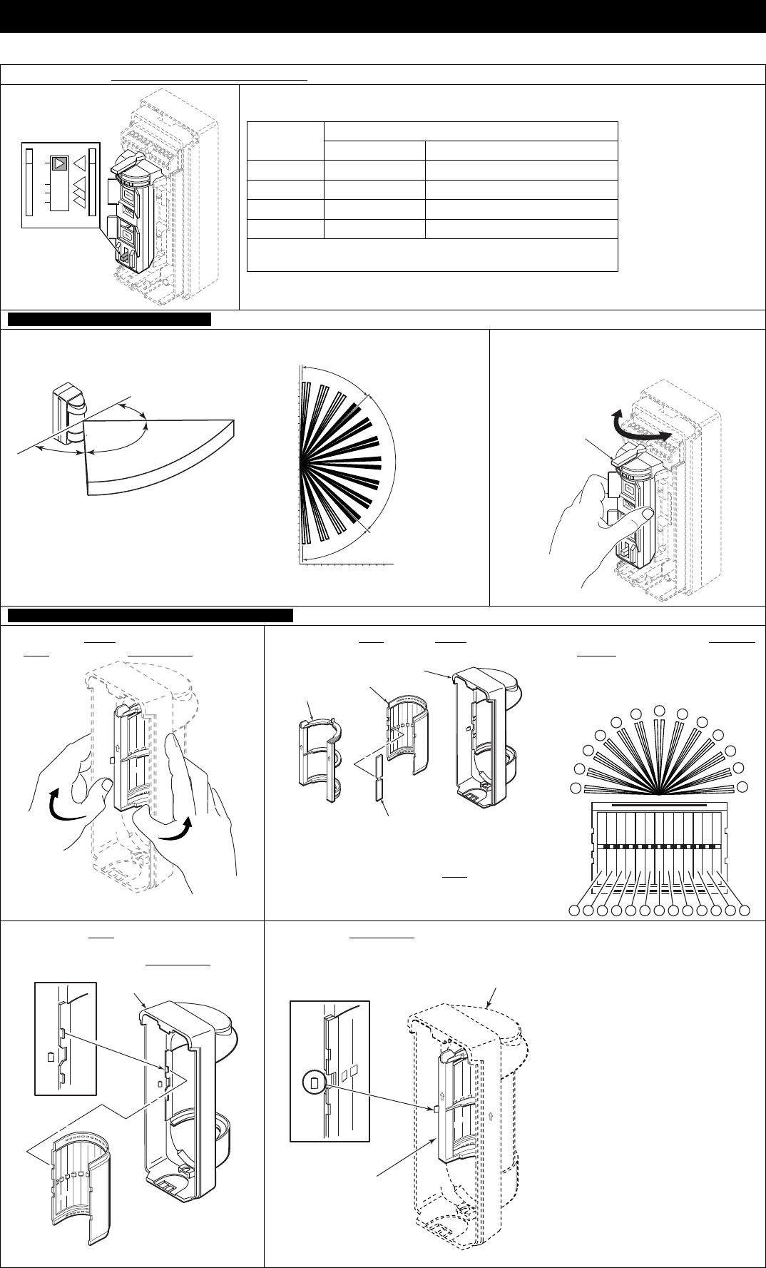
Press and slide the Detection Length Adjustment Switch to the desired position.
A
B
C
D
MAX DETECTION LENGTH
POSITION STANDARD ENVIRONMENTAL Á
D 02.0m (6.7ft) 1.5 - 2.5m (5 - 8ft)
C 05.0m (16.7ft) 04 - 5.5m (13 - 18ft)
B 08.0m (26.7ft) 06 - 10m (20 - 33.3ft)
A 12.0m (40.0ft) 10 - 15m (33.3 - 50ft)
Á Detection length may vary due to environmental conditions.
Detection height = 1m (3.3ft)
SET THE DETECTION AREA ANLGLE
1. The detection area angle is 90° with 7
fingers as shown.
90o
45o
45o
Top view
012
10
5
5
12
12
0
10
10
5
(m)
(m)
45 Adjustable
Active detection
fingers.
o
45 Adjustable
o
2. Hold the sensor and turn it to the desired
direction. Each click represents 15° of
change.
Adjust to
desired direction
IF NECESSARY, CONFIGURE DETECTION MASKING
1. Spread the Cover and gently press on the
Lens to remove the Lens Holder.
2. Separate the Lens from the Cover.
Cover
Lens
Area Masking
Plate
Lens
Holder
3. Identify the segments on the Lens to be masked.
4. Then apply the adhesive Masking
Strip(s), as necessary, inside the
lens to cover the desired
segments.
113
2
3
4
5
678
9
10
12
11
113
2345678910 12
11
5. Replace the Lens by aligning the 4 cutouts
on the lens to the 4 projections on the cover.
Snap in place with the Lens Holder.
Cover
Lens
6. Ensure the Lens Holder is held by the left and
right cover prongs and the two tabs are engaged.
Cover
Lens
Holder
5800-OD Wireless Outdoor Motion Sensor – Installation Instructions
– 4 –
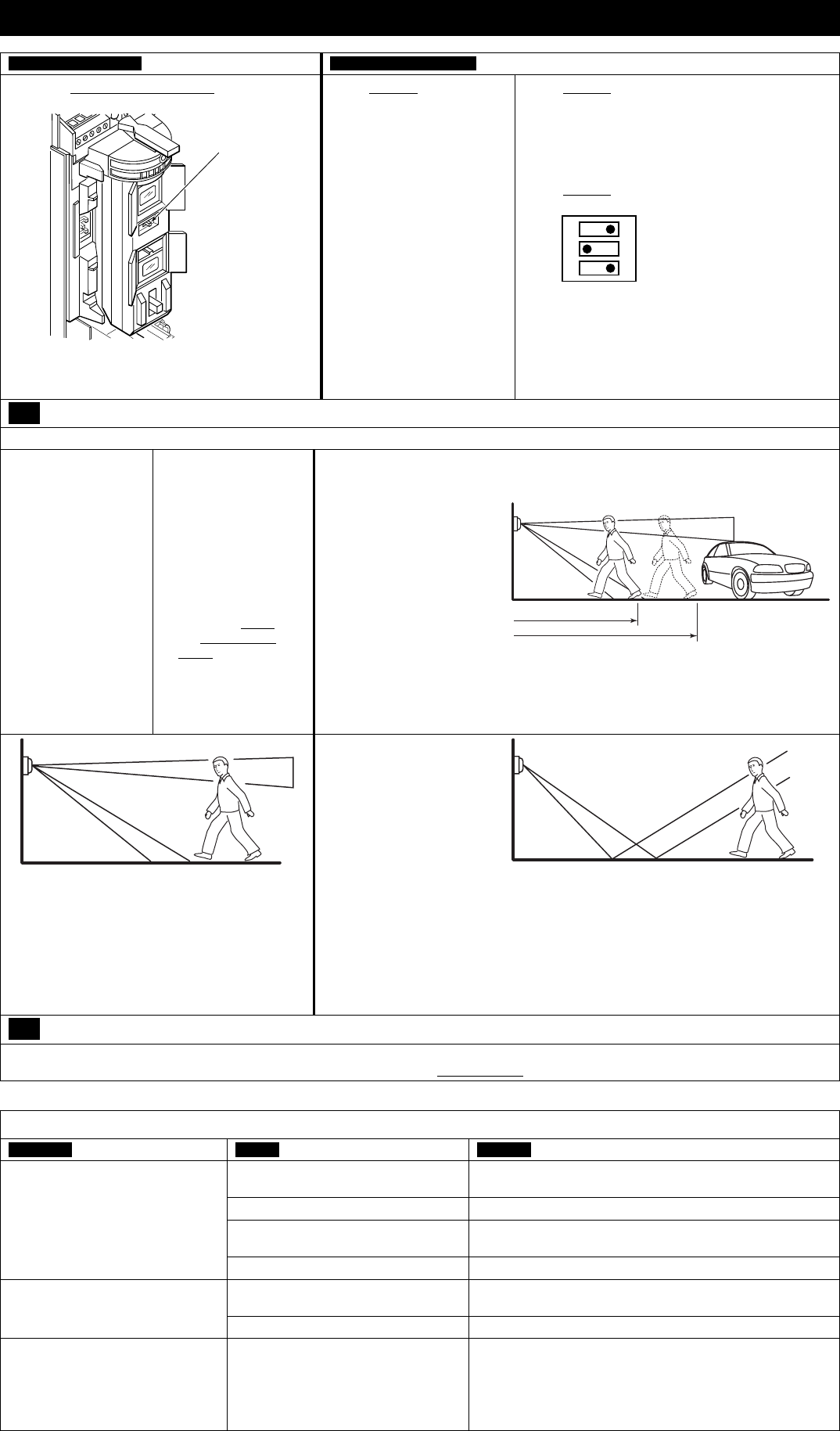
SET THE SENSITIVITY SET THE DIP SWITCHES
1. Set the Sensitivity Select Switch to the desired
sensitivity.
Sensitivity
Select Switch
(L,M,H)
Notes:
When greater sensitivity is desired, select "H".
When conditions are poor select "L".
1. Set switch 2 for the desired
Battery Saving Timer
period.
Note: The alarm output
activations are limited by
the timer selection (5 or
120 seconds). Even if there
are continuous alarm
events, the alarm output
operates only once in the
selected timer period. This
can be 5 or 120 seconds.
120s – Default Setting
5s – Used when frequent
alarm transmission is re-
quired. Battery life will be
shortened when using this
setting.
2. Set switch 3 for the desired Pulse Count
(selectable for 2 or 4).
Pulse Count of 2 = detection can be made with
as little as two steps.
Pulse Count of 4 = detection can be made with
as little as four steps.
3. Set switch 1 to enable the Walk Test, see the
instructions below.
ON 1. Walk Test
5s 2. Battery Saving Timer
2 3. Pulse Count
ON
123
OFF
120s
4
6 Perform a Walk Test
NOTE: With the Walk Test switch set to ON the LED will light when the detector is tripped, and the alarm is generated instantly.
1. Set the walk test
switch (DIP switch
1) to ON. Replace
the cover.
2. Perform a walk test
through the
detection area, and
verify satisfactory
results.
3. Allow the detection
area to remain
static and check for
false or unwanted
detections.
4. If necessary, adjust
the detection area
(see Perform Settings
& Adjustments).
5. Repeat the walk test
through the detection
area, and verify
satisfactory results.
6. Set the walk test
switch to OFF, and
secure the Cover with
the Captive Lock
Screw.
Notes:
If normal car or people
traffic pass close to the
detection area, adjust the
detection area 1.5 to 2.0m
(5 to 7ft) shorter to reduce
false detections. This also
allows for changes due to
environmental thermal
conditions.
If the detection length is
adjusted to position "A"
[12m (40ft)], the detection
area may increase when
there is a big temperature
difference between the
moving object and the
background.
If this causes a problem, adjust the detection length
to position "B". Then walk test to verify satisfactory
results.
Approx.8m (27ft)
position B
Approx.12m (40ft)
WALK TEST
This sensor has a multi-
level detection pattern
(from side view). A heat
source beyond the
detection area may cause
the detector to issue a
false alarm by reflecting
off the ground. Examples
include puddles, wet
surfaces, very smooth
asphalt or concrete
surfaces.
If this causes a problem,
adjust the detection
length to position "B".
Then perform a walk test
to verify satisfactory
results.
7 Program the Control Panel
Prior to use in the system, you must “enroll” the transmitter's serial number in the control panel. Refer to the control panel’s instructions for
further details. During programming, the transmitter shall be treated as RF supervised . (Mandatory for UL installations.)
TROUBLESHOOTING
SYMPTOM CAUSE REMEDY
Batteries are incorrectly installed or
dead.
Check for correct battery installation, or replace dead
batteries.
No detection, when walking
through the detection area.
Wiring is faulty or loose. Check all connectors and wiring.
Water in unit. Check for cracks in the housing that would allow water
infiltration. Replace unit.
Transmitter or PIR sensor is faulty. Replace unit.
No detection occasionally, or poor
detection.
Sensitivity is set too low. Try a higher sensitivity setting.
Detection area is not set correctly. Perform a Settings & Adjustments procedure.
Low battery fault indicated on
system keypad display.
Batteries are very low or dead. Replace batteries.
5800-OD Wireless Outdoor Motion Sensor – Installation Instructions
– 5 –
TROUBLESHOOTING
SYMPTOM CAUSE REMEDY
Alarms when no one is walking
through the detection area.
Sensor is not perpendicular to ground. Remount and align sensor so the detection area is parallel to
the ground.
Sensor is detecting moving trees,
bushes, or a strong source of light.
Check for moving trees, or bushes or a strong light source.
Perform a Settings & Adjustments procedure.
Lower detection area is too long. Set Detection Length to a shorter range.
A heat source in the area may be
causing an abrupt temperature
change.
Move or remove the heat source.
Mask the area pointing to the source of heat, or shorten the
Detection Length.
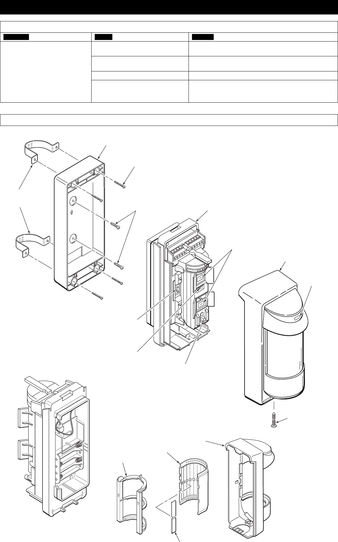
COMPONENT IDENTIFICATION
Mounting Screws
T4 x 20 Detector
Sensor
(Do not touch)
Cover
LED
Indicator
Cover
Lens
Back Box
M4 x 30 (4 places)
Captive
Lock Screw
Masking Strip
(Use as required)
Lens
Holder
UP
DIP Switch
Sensitivity Select
Switch Detection Length
Ajustment Switch
Pole
Bracket

5800-OD Wireless Outdoor Motion Sensor – Installation Instructions
USER NOTIFICATION
The user shall not make any changes or modifications to the equipment unless authorized by the installation Instructions or User's Manual.
Unauthorized changes or modifications could void the user's authority to operate the equipment.
LIMITATIONS OF THE PIR MOTION DETECTOR
While the Intrusion Detector is a highly reliable intrusion detection device, it does not offer guaranteed protection against burglary. Any Intrusion
Detection device is subject to compromise or failure to warn for a variety of reasons:
• Passive Infrared Motion Detectors can detect intrusion only within the designed ranges as diagrammed in this installation manual.
• Passive Infrared Motion Detectors do not provide volumetric area protection. They do create multiple beams of protection, and intrusion can be
detected only in unobstructed areas covered by those beams.
• Passive Infrared Detectors cannot detect motion or intrusion that takes place behind walls, ceilings, floors, closed doors, glass partitions, glass
doors, or windows.
• Mechanical tampering, masking, painting, or spraying of any material on the lenses, windows or any part of the optical system can reduce the
detection ability of the Passive Infrared Motion Detector.
• Passive Infrared Detectors sense changes in temperature; however, as the ambient temperature of the protected area approaches the
temperature range of 90° to 105°F (32° to 40°C), the detection performance can decrease.
• This Passive Infrared Detector will not operate without the appropriate battery installed, or if the battery is weak or improperly connected (i.e.,
reversed polarity).
• Passive Infrared Detectors, like other electrical devices, are subject to component failure. Even though this equipment is designed to last as
long as 10 years, the electronic components in it could fail at any time.
We have cited some of the most common reasons that a Passive Infrared Motion Detector can fail to catch intrusion. However, this does not imply
that these are the only reasons, and therefore it is recommended that weekly testing of this type of unit, in conjunction with weekly testing of the
entire alarm system, be performed to ensure that the detectors are working properly.
Installing an alarm system may make the owner eligible for a lower insurance rate, but an alarm system is not a substitute for insurance.
Homeowners, property owners and renters should continue to act prudently in protecting themselves and continue to insure their lives and
property.
We continue to develop new and improved protection devices. Users of alarm systems owe it to themselves and their loved ones to learn about
these developments.
FCC / IC STATEMENT
This device complies with Part 15 of the FCC Rules, and RSS210 of IC.
Operation is subject to the following two conditions: (1) This device may not cause harmful interference. (2) This device must accept any interference
received, including interference that may cause undesired operation.
WARRANTY
For the latest warranty information, please go to:
http://www.security.honeywell.com/hsc/resources/wa/
To obtain applicable EU compliance Declaration of Conformities for this product, please refer to our Website,
http://www.security.honeywell.com/hsce/international/index.html.
For any additional information regarding the compliance of this product to any EU specific requirements, please contact:
Quality Assurance Department,
Honeywell Security & Custom Electronics,
Newhouse Industrial Estate
Motherwell,
Lanarkshire ML1 5SB,
Scotland, United Kingdom.
Tel: +44(0)1698 738200
Email: UK64Sales@Honeywell.
© 2008 Honeywell International Inc. Honeywell is a registered trademark of Honeywell International Inc.
All other trademarks are the properties of their respective owners. All rights reserved.
Please contact your local authorized Honeywell representative for product warranty information.
ÊPREK15009nŠ
PREK15009 5/08 Rev. A
FCC & IC