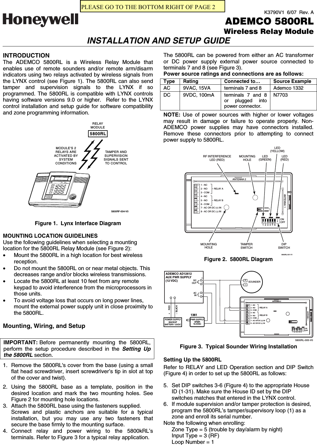
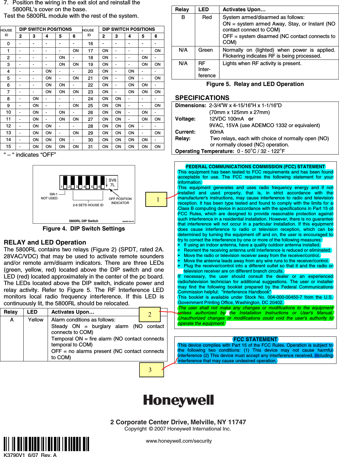
Ademco 8DL5800RL-2 Wireless Relay Module User Manual K3790V1

Honeywell International Inc. Wireless Relay Module K3790V1

Users Manual

K3790V1  6/07  Rev. AADEMCO 5800RL Wireless Relay ModuleINSTALLATION AND SETUP GUIDE  INTRODUCTION The ADEMCO 5800RL is a Wireless Relay Module that enables use of remote sounders and/or remote arm/disarm indicators using two relays activated by wireless signals from the LYNX control (see Figure 1). The 5800RL can also send tamper and supervision signals to the LYNX if so programmed. The 5800RL is compatible with LYNX controls having software versions 9.0 or higher.  Refer to the LYNX control installation and setup guide for software compatibility and zone programming information.  5800RLRELAYMODULETAMPER ANDSUPERVISIONSIGNALS SENTTO CONTROLMODULE'S 2RELAYS AREACTIVATED BYSYSTEMCONDITIONSAWAYOFFSTAYAUX5800RF-004-V0  Figure 1.  Lynx Interface Diagram  MOUNTING LOCATION GUIDELINES Use the following guidelines when selecting a mounting location for the 5800RL Relay Module (see Figure 2): •  Mount the 5800RL in a high location for best wireless reception. •  Do not mount the 5800RL on or near metal objects. This decreases range and/or blocks wireless transmissions. •  Locate the 5800RL at least 10 feet from any remote keypad to avoid interference from the microprocessors in those units. •  To avoid voltage loss that occurs on long power lines, mount the external power supply unit in close proximity to the 5800RL.  Mounting, Wiring, and Setup   IMPORTANT:  Before permanently mounting the 5800RL, perform the setup procedure described in the Setting Up the 5800RL section.  1.  Remove the 5800RL's cover from the base (using a small flat head screwdriver, insert screwdriver’s tip in slot at top of the cover and twist).  2. Using the 5800RL base as a template, position in the desired location and mark the two mounting holes. See Figure 2 for mounting hole locations. 3.  Attach the 5800RL base using the fasteners supplied. Screws and plastic anchors are suitable for a typical installation, but you may use any two fasteners that secure the base firmly to the mounting surface. 4. Connect relay and power wiring to the 5800kRL’s terminals. Refer to Figure 3 for a typical relay application. The 5800RL can be powered from either an AC transformer or DC power supply external power source connected to terminals 7 and 8 (see Figure 3). Power source ratings and connections are as follows: Type Rating  Connected to…  Source Example AC  9VAC, 15VA  terminals 7 and 8  Ademco 1332 DC 9VDC, 100mA  N7703   terminals 7 and 8 or plugged into power connector.   NOTE:  Use of power sources with higher or lower voltages may result in damage or failure to operate properly. Non-ADEMCO power supplies may have connectors installed. Remove these connectors prior to attempting to connect power supply to 5800RL.  TAMPERSWITCH2 - NO3 - COM4 - NC5 - NO6 - COM7 - AC OR DC (+) IN1 - NC8 - AC OR DC (  ) IN RELAY ARELAY B5800RL-001-V1LED(RED)LED(YELLOW)LED(GREEN)RF INTERFERENCELED (RED)ANTENNA 2ANTENNA 1DIPSWITCHMOUNTINGHOLEMOUNTINGHOLE123456ONOFF Figure 2.  5800RL Diagram   2 - NO3 - COM4 - NC5 - NO6 - COM7 - AC OR DC (+) IN1 - NC8 - AC OR DC (  ) IN RELAY ARELAY B5800RL-005-V0ANTENNA 2SOUNDERANTENNA 1123456ONOFFADEMCO AD12612AUX PWR SUPPLY(12 VDC)ACIN+_DCOUT1361+_REDBLACKPOWER SUPPLYBACKUPBATTERY 12VDC+PWR SUPPLYXFMR16.5VAC Figure 3.  Typical Sounder Wiring Installation  Setting Up the 5800RL Refer to RELAY and LED Operation section and DIP Switch (Figure 4) in order to set up the 5800RL as follows:  5.  Set DIP switches 3-6 (Figure 4) to the appropriate House ID (1-31). Make sure the House ID set by the DIP switches matches that entered in the LYNX control. 6.  If module supervision and/or tamper protection is desired, program the 5800RL’s tamper/supervisory loop (1) as a zone and enroll its serial number. Note the following when enrolling: Zone Type = 5 (trouble by day/alarm by night) Input Type = 3 (RF) Loop Number = 1 PLEASE GO TO THE BOTTOM RIGHT OF PAGE 2
7.  Position the wiring in the exit slot and reinstall the 5800RL’s cover on the base. Test the 5800RL module with the rest of the system.  DIP SWITCH POSITIONS  DIP SWITCH POSITIONS HOUSE ID 2 3 4 5 6 HOUSE ID 2 3 4  5 6 0  -  - - -  -  16 - - -  - - 1  - - - - ON 17 ON -  -  -  ON 2  - - - ON -  18 ON -  -  ON - 3  - - - ON ON 19 ON -  -  ON ON 4  - - ON - -  20 ON -  ON  -  - 5  - - ON - ON 21 ON -  ON  -  ON 6  - - ON ON -  22 ON -  ON  ON - 7  - - ON ON ON 23 ON -  ON  ON ON 8  - ON - - -  24 ON ON -  -  - 9  - ON - - ON 25 ON ON -  -  ON 10  - ON - ON -  26 ON ON -  ON - 11  - ON - ON ON 27 ON ON -  ON ON 12  - ON ON - -  28 ON ON ON  -  - 13  - ON ON - ON 29 ON ON ON  -  ON 14  - ON ON ON -  30 ON ON ON  ON - 15  - ON ON ON ON 31 ON ON ON  ON ON “ – “ indicates “OFF”  2345612-6 SETS HOUSE IDSW-1NOT USED5800RL DIP Switch5800RF-003-V0OFF POSITIONINDICATORSV67L Figure 4.  DIP Switch Settings  RELAY and LED Operation The 5800RL contains two relays (Figure 2) (SPDT, rated 2A. 28VAC/VDC) that may be used to activate remote sounders and/or remote arm/disarm indicators. There are three LEDs (green, yellow, red) located above the DIP switch and one LED (red) located approximately in the center of the pc board. The LEDs located above the DIP switch, indicate power and relay activity. Refer to Figure 5. The RF Interference LED monitors local radio frequency interference. If this LED is continuously lit, the 5800RL should be relocated.   Relay LED  Activates Upon… A  Yellow  Alarm conditions as follows: Steady ON = burglary alarm (NO contact connects to COM) Temporal ON = fire alarm (NO contact connects temporal to COM) OFF = no alarms present (NC contact connects to COM)  Relay LED  Activates Upon… B  Red  System armed/disarmed as follows: ON = system armed Away, Stay, or Instant (NO contact connect to COM) OFF = system disarmed (NC contact connects to COM) N/A Green Normally on (lighted) when power is applied. Flickering indicates RF is being processed. N/A  RF Inter-ference Lights when RF activity is present. Figure 5.  Relay and LED Operation  SPECIFICATIONS Dimensions:  2-3/4”W x 4-15/16”H x 1-1/16”D (70mm x 125mm x 27mm) Voltage:    12VDC 100mA   or 9VAC, 15VA (use ADEMCO 1332 or equivalent) Current:    60mA Relay:   Two relays, each with choice of normally open (NO)   or normally closed (NC) operation. Operating Temperature:  0 - 50°C / 32 - 122°F  FEDERAL COMMUNICATIONS COMMISSION (FCC) STATEMENT This equipment has been tested to FCC requirements and has been found acceptable for use. The FCC requires the following statement for your information: This equipment generates and uses radio frequency energy and if not installed and used properly, that is, in strict accordance with the manufacturer's instructions, may cause interference to radio and television reception. It has been type tested and found to comply with the limits for a Class B computing device in accordance with the specifications in Part 15 of FCC Rules, which are designed to provide reasonable protection against such interference in a residential installation. However, there is no guarantee that interference will not occur in a particular installation. If this equipment does cause interference to radio or television reception, which can be determined by turning the equipment off and on, the user is encouraged to try to correct the interference by one or more of the following measures: •  If using an indoor antenna, have a quality outdoor antenna installed. •  Reorient the receiving antenna until interference is reduced or eliminated.  •  Move the radio or television receiver away from the receiver/control. •  Move the antenna leads away from any wire runs to the receiver/control. •  Plug the receiver/control into a different outlet so that it and the radio or television receiver are on different branch circuits. If necessary, the user should consult the dealer or an experienced radio/television technician for additional suggestions. The user or installer may find the following booklet prepared by the Federal Communications Commission helpful:  "Interference Handbook" This booklet is available under Stock No. 004-000-00450-7 from the U.S. Government Printing Office, Washington, DC 20402. The user shall not make any changes or modifications to the equipment unless authorized by the Installation Instructions or User's Manual.  Unauthorized changes or modifications could void the user's authority to operate the equipment.  FCC STATEMENT This device complies with Part 15 of the FCC Rules. Operation is subject to the following two conditions: (1) This device may not cause harmful interference (2) This device must accept any interference received, including interference that may cause undesired operation.               ÊK3790V1UŠ K3790V1  6/07  Rev. A    2 Corporate Center Drive, Melville, NY 11747Copyright © 2007 Honeywell International Inc.www.honeywell.com/security        1     2     3

Navigation menu