Ademco 8DL5804AP Key fob security transmitter User Manual 5804AP II
Honeywell International Inc. Key fob security transmitter 5804AP II
UserManual.wiki
>
Ademco
>
8DL5804AP User Manual
II with FCC ID No and Part 15 Statment
Navigation menu
Upload a User Manual
Namespaces
Wiki Guide
HTML
PDF
Info
Views
User Manual
Discussion / Help
Navigation
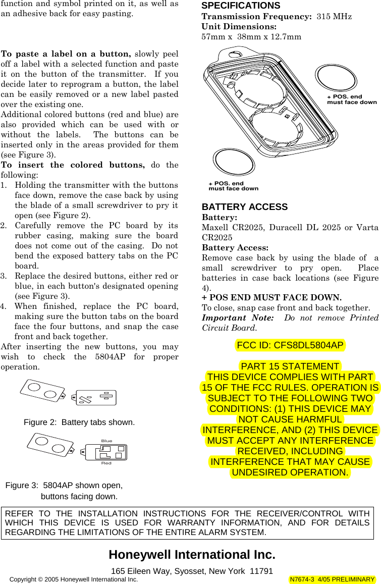
![N7674-3 4/05 PRELIMINARY Honeywell International Inc. 5804AP WIRELESS KEY TRANSMITTER INSTALLATION INSTRUCTIONS For use with QED control panels ONLY! GENERAL INFORMATION The 5804AP is a compact, 4-button portable wireless transmitter intended for use only with wireless alarm systems that support QED 5800AP series receivers. Each button on the transmitter may be programmed for any zone response, but is typically used for arming, disarming, panic, and relay activation. Each button's response is assigned when programming the transmitter at the control (see the QED control's installation instructions). The 5804AP is powered by two replaceable lithium batteries designed to provide up to 4 years of life. For battery installation, see Battery Access. PROGRAMMING THE 5804AP Each 5804AP is assigned a unique serial number during manufacture. Each button on the unit also has a distinct "loop" number (refer to Figure 1 that you must programme into the QED control panel during installation. Assign each button to an individual zone and designate the Input Type as "BR" (Button Type RF). You must program the lower left-hand button (Loop 4; see Figure 1). If it is not programmed, a "check" condition will occur when the button is accidentally pressed. You can also program the unit by entering the serial number manually through a keypad or by downloading it to the control panel using Ademco's V-LINK Downloading Software (Rev. 4 or higher). If you use one of these methods, be sure to include the loop number of each button (see Figure 1). For complete details on how to program the 5804AP transmitter's serial number at the control panel, see the QED control unit's installation instructions. Note: Buttons on this transmitter must be pressed for at least 1/2 second to activate the transmitter. This feature minimizes the possibility of accidental transmissions. YOU MUSTPROGRAMMETHIS BUTTONLOOP 3LOOP 1LOOP 2LOOP 4 Figure 1: 5804AP showing button designations If you choose not to use the lower left-hand button (Button 4), do the following: 1. Program it into the system anyway (see previous explanation). 2. After the serial number has been programmed, re-enter Zone Programming for that zone. 3. At the "Zone Type" prompt, enter 00 and press [*]. On VISTA 20/4111XM panels, the system will ask whether you want to permanently delete that zone. Enter 0 (No). This will cause the system to retain the serial number, but render the button inactive. On 4140XMPT2/VISTA-120 panels and above, continue to press [*] until you see the "Enter Zone No?" prompt. At this point, press 00 and [*]. Then enter *99 to exit program mode. INSTALLING ADHESIVE LABELS AND BUTTONS The 5804AP is supplied with colored buttons (red and blue) and colored adhesive identification labels (blue, red, gray, and green). Each label has a specified command](https://usermanual.wiki/Ademco/8DL5804AP/User-Guide-579365-Page-1.png)