Ademco 8DL5804AP Key fob security transmitter User Manual 5804AP II
Honeywell International Inc. Key fob security transmitter 5804AP II
Ademco >
II with FCC ID No and Part 15 Statment
N7674-3 4/05 PRELIMINARY
Honeywell International Inc. 5804AP
WIRELESS KEY
TRANSMITTER
INSTALLATION INSTRUCTIONS
For use with QED control panels ONLY!
GENERAL INFORMATION
The 5804AP is a compact, 4-button portable
wireless transmitter intended for use only
with wireless alarm systems that support
QED 5800AP series receivers. Each button
on the transmitter may be programmed for
any zone response, but is typically used for
arming, disarming, panic, and relay
activation. Each button's response is
assigned when programming the transmitter
at the control (see the QED control's
installation instructions).
The 5804AP is powered by two replaceable
lithium batteries designed to provide up to 4
years of life. For battery installation, see
Battery Access.
PROGRAMMING THE 5804AP
Each 5804AP is assigned a unique serial
number during manufacture. Each button on
the unit also has a distinct "loop" number
(refer to Figure 1 that you must programme
into the QED control panel during
installation. Assign each button to an
individual zone and designate the Input Type
as "BR" (Button Type RF). You must
program the lower left-hand button (Loop 4;
see Figure 1). If it is not programmed, a
"check" condition will occur when the button
is accidentally pressed.
You can also program the unit by entering
the serial number manually through a
keypad or by downloading it to the control
panel using Ademco's V-LINK Downloading
Software (Rev. 4 or higher). If you use one of
these methods, be sure to include the loop
number of each button (see Figure 1).
For complete details on how to program the
5804AP transmitter's serial number at the
control panel, see the QED control unit's
installation instructions.
Note: Buttons on this transmitter must be
pressed for at least 1/2 second to activate the
transmitter. This feature minimizes the
possibility of accidental transmissions.
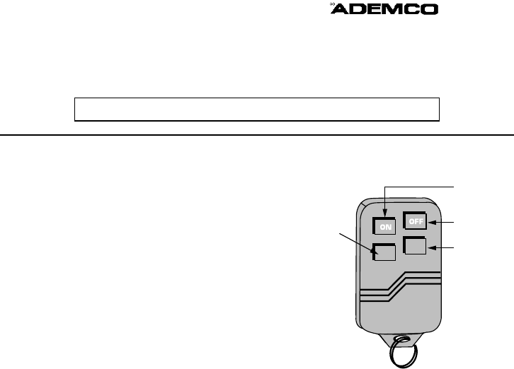
YOU MUST
PROGRAMME
THIS BUTTON
LOOP 3
LOOP 1
LOOP 2
LOOP 4
Figure 1: 5804AP showing button designations
If you choose not to use the lower left-hand
button (Button 4), do the following:
1. Program it into the system anyway (see
previous explanation).
2. After the serial number has been
programmed, re-enter Zone Programming
for that zone.
3. At the "Zone Type" prompt, enter 00 and
press [*]. On VISTA 20/4111XM panels,
the system will ask whether you want to
permanently delete that zone. Enter 0
(No). This will cause the system to retain
the serial number, but render the button
inactive. On 4140XMPT2/VISTA-120
panels and above, continue to press [*]
until you see the "Enter Zone No?"
prompt. At this point, press 00 and [*].
Then enter *99 to exit program mode.
INSTALLING ADHESIVE LABELS AND
BUTTONS
The 5804AP is supplied with colored buttons
(red and blue) and colored adhesive
identification labels (blue, red, gray, and
green). Each label has a specified command
function and symbol printed on it, as well as
an adhesive back for easy pasting.
To paste a label on a button, slowly peel
off a label with a selected function and paste
it on the button of the transmitter. If you
decide later to reprogram a button, the label
can be easily removed or a new label pasted
over the existing one.
Additional colored buttons (red and blue) are
also provided which can be used with or
without the labels. The buttons can be
inserted only in the areas provided for them
(see Figure 3).
To insert the colored buttons, do the
following:
1. Holding the transmitter with the buttons
face down, remove the case back by using
the blade of a small screwdriver to pry it
open (see Figure 2).
2. Carefully remove the PC board by its
rubber casing, making sure the board
does not come out of the casing. Do not
bend the exposed battery tabs on the PC
board.
3. Replace the desired buttons, either red or
blue, in each button's designated opening
(see Figure 3).
4. When finished, replace the PC board,
making sure the button tabs on the board
face the four buttons, and snap the case
front and back together.
After inserting the new buttons, you may
wish to check the 5804AP for proper
operation.
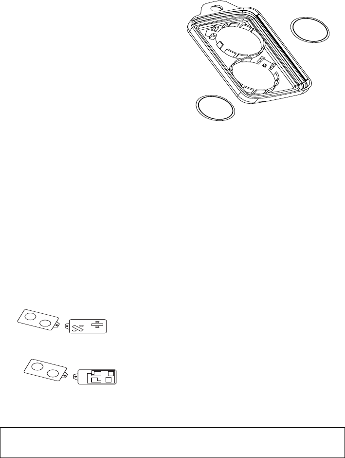
Battery Tabs Shown
Figure 2: Battery tabs shown.
Blue
Red
Figure 3: 5804AP shown open,
buttons facing down.
SPECIFICATIONS
Transmission Frequency: 315 MHz
Unit Dimensions:
57mm x 38mm x 12.7mm
+ POS. end
must face down
+ POS. end
must face down
BATTERY ACCESS
Battery:
Maxell CR2025, Duracell DL 2025 or Varta
CR2025
Battery Access:
Remove case back by using the blade of a
small screwdriver to pry open. Place
batteries in case back locations (see Figure
4).
+ POS END MUST FACE DOWN.
To close, snap case front and back together.
Important Note: Do not remove Printed
Circuit Board.
FCC ID: CFS8DL5804AP
PART 15 STATEMENT
THIS DEVICE COMPLIES WITH PART
15 OF THE FCC RULES. OPERATION IS
SUBJECT TO THE FOLLOWING TWO
CONDITIONS: (1) THIS DEVICE MAY
NOT CAUSE HARMFUL
INTERFERENCE, AND (2) THIS DEVICE
MUST ACCEPT ANY INTERFERENCE
RECEIVED, INCLUDING
INTERFERENCE THAT MAY CAUSE
UNDESIRED OPERATION.
REFER TO THE INSTALLATION INSTRUCTIONS FOR THE RECEIVER/CONTROL WITH
WHICH THIS DEVICE IS USED FOR WARRANTY INFORMATION, AND FOR DETAILS
REGARDING THE LIMITATIONS OF THE ENTIRE ALARM SYSTEM.
Honeywell International Inc.
165 Eileen Way, Syosset, New York 11791
Copyright © 2005 Honeywell International Inc. N7674-3 4/05 PRELIMINARY