Ademco 8DL5804BD-1 Bi-direction Key User Manual N8209V1 5804BD ii
Honeywell International Inc. Bi-direction Key N8209V1 5804BD ii
UserManual.wiki
>
Ademco
>
8DL5804BD 1 User Manual
Users Manual
Navigation menu
Upload a User Manual
Namespaces
Wiki Guide
HTML
PDF
Info
Views
User Manual
Discussion / Help
Navigation
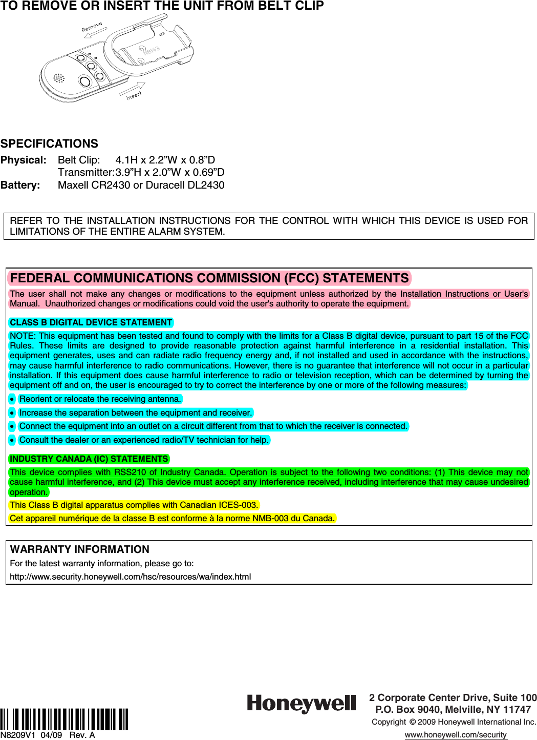
![Programming a House ID in the Alarm Control • On VISTA 32/40/50/50P and up, use Device Programming mode to enable the RF receiver and enter the House ID number. • On VISTA-20P, 15P, 10P, and compatible variants, go to field ✶24 and enter the House ID number. PROGRAMMING THE BUTTONS Each 5804BD is assigned a unique serial number during manufacturing. Each button on the unit also has a unique “loop” number that must be programmed into the control panel during installation. Assign each button to an individual zone number and program the Input Type as “BR” --Button Type RF (entry of “5”) in the control’s Zone Programming mode. Then, input the serial number by one of the following methods: • “Enroll” the serial number of the device into the system as described in the control panel’s Installation Instructions. • Enter the serial number manually through the keypad. • Enter the serial number using downloading software. Be sure to include the loop number of each button during programming (see loop assignments on previous page). Button C If you choose not to use the “C” button, you must do the following to avoid a “Check” condition when the button is accidentally pressed: 1. Assign this button to a zone (see Programming the Buttons above). 2. After the serial number has been programmed, re-enter Zone Programming for that zone. 3. At the “Zone Type” prompt, enter 00 and press [✶]. a) On VISTA-30 controls and below, the system will ask whether you want to permanently delete that zone. Enter 0 (No). This will cause the system to retain the serial number, but render the button inactive. b) On VISTA-40 and above, continue to press [✶] until you see the “Enter zone No?” prompt again. At this point, Press 00 and [✶]. Then press ✶ 99 to exit Program mode. Arm/Disarm Button If a button is assigned to a zone type 20 (Arm Stay), 21 (Arm Away), and 22 (Disarm), you must do the following: On Vista 32/40/50/50P/100, and up You must assign a user to the button in order for it to operate. To assign a user number to the Arm/Disarm button: 1. Enter [4-digit User Code] + 8 + [User No.] + [4-digit new User Code]. 2. Answer Yes or No to the “Open/Close Report ?” question. 3. Answer Yes to the “RF Button ?” question. 4. Enter the zone number assigned to the Arm/Disarm button. 5. Keypad shows the summary of user information on its display. 6. Test Arm/Disarm button to make sure it operates correctly. On Vista-20P/15P/10P, and compatible variants You do not have to assign a user to the button. The panel will report the zone number as the user number to the central station. OPERATING THE BUTTONS To Activate a Button To activate programmed function on a button, press and hold the button down until the yellow LED flashes (2 beeps will be heard), and then release it. To Request System Status Because the 5804BD is a bi-directional device, users can check the system status before arming or disarming their system. To check system status, press and release any button momentarily. The yellow LED will flash after you release the button (1 beep will be heard). After a second or two, the 5804BD will display the system status information using a combination of LED and sounder activity (see the System Status Indications Table, below). If 5804BD does not receive system status information from the panel for approximately five seconds, it will generate a long (1 second) beep and shut itself down. It will also shut itself down if there is no button activity within five seconds of receiving a status update.](https://usermanual.wiki/Ademco/8DL5804BD-1/User-Guide-1102760-Page-2.png)
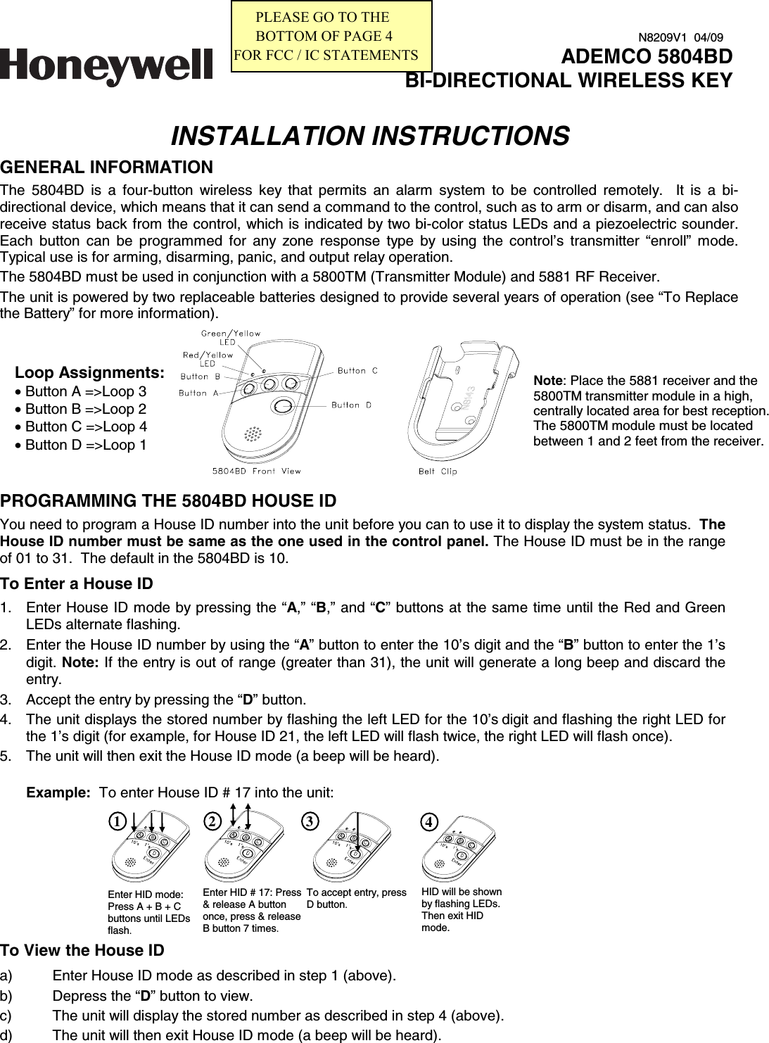
![WARNING! This device may not receive the system status properly if it operates within a few feet of the 5881 RF receiver. SYSTEM STATUS INDICATIONS TABLE LED LED Condition Sounder System Status Red On Steady On Steady Flashing Flashing Flashing 2 Beeps 3 Beeps Pulsing Steady Silent Armed Away or Maximum Armed Stay or Instant Fire Alarm in progress Armed, Burglary Alarm in progress Alarm Memory Green On Steady Flashing 1 Beep Silent Disarmed, Ready to Arm Disarmed, Not Ready to Arm Yellow (right) Flashing Silent Indicates RF transmission Red & Green Alternately Flashing Silent In Enter House ID Mode Green Flashing Flashing Pulsing Silent System in Trouble System Not Ready MULTIPLE BUTTON OPERATIONS The 5804BD can generate the same responses as keypad panic key pairs of [✶] + [#] and [✶] + [1] by depressing “A” + “C” and “B” + “D” button pairs, respectively. You must depress the button pair for at least two seconds for the 5804BD to recognize the button pair command. These button pairs allow the user to activate panic, fire, and medical alarms depending on control panel programming. Failure of Replaceable Batteries This wireless key has been designed to provide several years of battery life under normal conditions. The expected battery life is a function of the device environment, usage and type. Ambient conditions such as high humidity, high or low temperatures, or large temperature fluctuations may reduce the expected battery life. This device will report a low battery condition to the control panel as a trouble condition, when the batteries need to be replaced. In addition the yellow LED will not flash when a button is pressed. However, if the device is unused for a long period of time, it may fail to operate as expected. Regular testing and maintenance will keep the system in good operating condition for the lifetime of the product. IMPORTANT! This wireless key is intended as a convenience to the user and should not be considered as a life safety device. If life safety is important, please select a supervised wireless key (e.g. type 5802MN). Low-Battery Indication When the unit goes into a low battery condition, the yellow LED will not flash when a button is pressed. Change both batteries immediately. TO INSTALL / REPLACE BATTERIES 1. Remove the screw from the case back. 2. Remove case back by using the blade of a small screwdriver to pry open. 3. Place batteries in case back locations (see diagram). Use CR2430 or DL2430 Lithium battery only. 4. Close the case by snapping case front and back together. 5. Replace the screw to secure the case. WARNING! Improperly installing the batteries will cause damage to the batteries.](https://usermanual.wiki/Ademco/8DL5804BD-1/User-Guide-1102760-Page-3.png)