Ademco 8DL5804BD-1 Bi-direction Key User Manual N8209V1 5804BD ii
Honeywell International Inc. Bi-direction Key N8209V1 5804BD ii
Ademco >
Users Manual
INSTALLATION INSTRUCTIONS
GENERAL INFORMATION
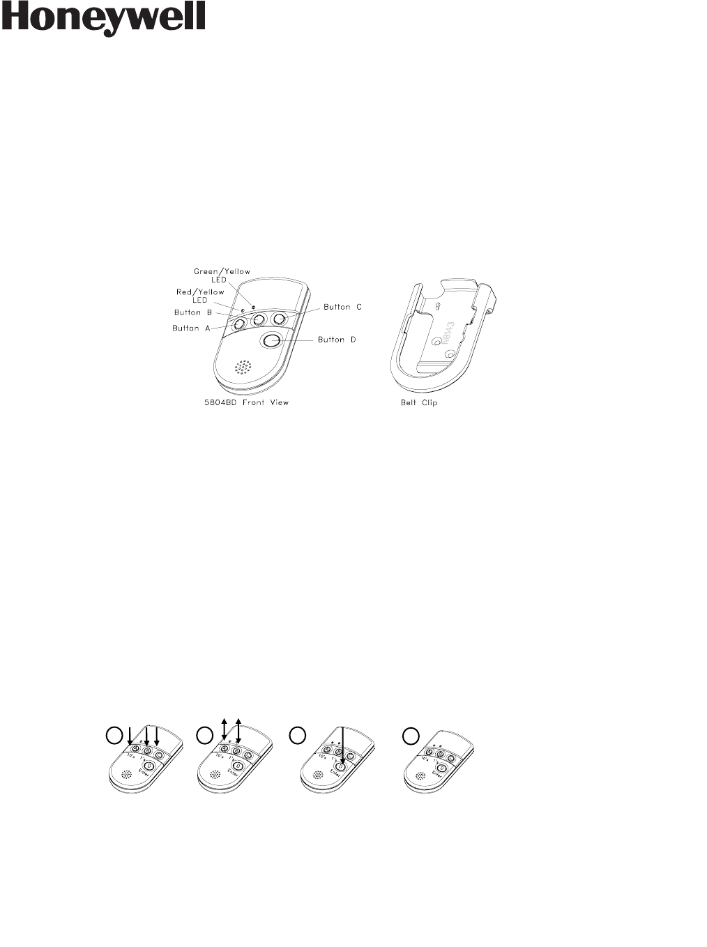
The 5804BD is a four-button wireless key that permits an alarm system to be controlled remotely. It is a bi-
directional device, which means that it can send a command to the control, such as to arm or disarm, and can also
receive status back from the control, which is indicated by two bi-color status LEDs and a piezoelectric sounder.
Each button can be programmed for any zone response type by using the control’s transmitter “enroll” mode.
Typical use is for arming, disarming, panic, and output relay operation.
The 5804BD must be used in conjunction with a 5800TM (Transmitter Module) and 5881 RF Receiver.
The unit is powered by two replaceable batteries designed to provide several years of operation (see “To Replace
the Battery” for more information).
PROGRAMMING THE 5804BD HOUSE ID
You need to program a House ID number into the unit before you can to use it to display the system status. The
House ID number must be same as the one used in the control panel. The House ID must be in the range
of 01 to 31. The default in the 5804BD is 10.
To Enter a House ID
1. Enter House ID mode by pressing the “A,” “B,” and “C” buttons at the same time until the Red and Green
LEDs alternate flashing.
2. Enter the House ID number by using the “A” button to enter the 10’s digit and the “B” button to enter the 1’s
digit. Note: If the entry is out of range (greater than 31), the unit will generate a long beep and discard the
entry.
3. Accept the entry by pressing the “D” button.
4. The unit displays the stored number by flashing the left LED for the 10’s digit and flashing the right LED for
the 1’s digit (for example, for House ID 21, the left LED will flash twice, the right LED will flash once).
5. The unit will then exit the House ID mode (a beep will be heard).
Example: To enter House ID # 17 into the unit:
To View the House ID
a) Enter House ID mode as described in step 1 (above).
b) Depress the “D” button to view.
c) The unit will display the stored number as described in step 4 (above).
d) The unit will then exit House ID mode (a beep will be heard).
ADEMCO 5804BD
BI-DIRECTIONAL WIRELESS KEY
N8209V1 04
/
09
Loop Assignments:
• Button A =>Loop 3
• Button B =>Loop 2
• Button C =>Loop 4
• Button D =>Loop 1
Note: Place the 5881 receiver and the
5800TM transmitter module in a high,
centrally located area for best reception.
The 5800TM module must be located
between 1 and 2 feet from the receiver.
Enter HID mode:
Press A + B + C
buttons until LEDs
flash.
Enter HID # 17: Press
& release A button
once, press & release
B button 7 times.
To accept entry, press
D button.
1 2 3 4
HID will be shown
by flashing LEDs.
Then exit HID
mode.
PLEASE GO TO THE
BOTTOM OF PAGE 4
FOR FCC / IC STATEMENTS

Programming a House ID in the Alarm Control
• On VISTA 32/40/50/50P and up, use Device Programming mode to enable the RF receiver and enter the
House ID number.
• On VISTA-20P, 15P, 10P, and compatible variants, go to field ✶24 and enter the House ID number.
PROGRAMMING THE BUTTONS
Each 5804BD is assigned a unique serial number during manufacturing. Each button on the unit also has a
unique “loop” number that must be programmed into the control panel during installation. Assign each button to an
individual zone number and program the Input Type as “BR” --Button Type RF (entry of “5”) in the control’s Zone
Programming mode. Then, input the serial number by one of the following methods:
• “Enroll” the serial number of the device into the system as described in the control panel’s Installation
Instructions.
• Enter the serial number manually through the keypad.
• Enter the serial number using downloading software.
Be sure to include the loop number of each button during programming (see loop assignments on previous page).
Button C
If you choose not to use the “C” button, you must do the following to avoid a “Check” condition when the button is
accidentally pressed:
1. Assign this button to a zone (see Programming the Buttons above).
2. After the serial number has been programmed, re-enter Zone Programming for that zone.
3. At the “Zone Type” prompt, enter 00 and press [✶].
a) On VISTA-30 controls and below, the system will ask whether you want to permanently delete that zone.
Enter 0 (No). This will cause the system to retain the serial number, but render the button inactive.
b) On VISTA-40 and above, continue to press [✶] until you see the “Enter zone No?” prompt again. At this
point, Press 00 and [✶]. Then press ✶ 99 to exit Program mode.
Arm/Disarm Button
If a button is assigned to a zone type 20 (Arm Stay), 21 (Arm Away), and 22 (Disarm), you must do the following:
On Vista 32/40/50/50P/100, and up
You must assign a user to the button in order for it to operate.
To assign a user number to the Arm/Disarm button:
1. Enter [4-digit User Code] + 8 + [User No.] + [4-digit new
User Code].
2. Answer Yes or No to the “Open/Close Report ?” question.
3. Answer Yes to the “RF Button ?” question.
4. Enter the zone number assigned to the Arm/Disarm
button.
5. Keypad shows the summary of user information on its
display.
6. Test Arm/Disarm button to make sure it operates
correctly.
On Vista-20P/15P/10P, and compatible
variants
You do not have to assign a user to the button. The panel
will report the zone number as the user number to the central
station.
OPERATING THE BUTTONS
To Activate a Button
To activate programmed function on a button, press and hold the button down until the yellow LED flashes (2
beeps will be heard), and then release it.
To Request System Status
Because the 5804BD is a bi-directional device, users can check the system status before arming or disarming
their system.
To check system status, press and release any button momentarily. The yellow LED will flash after you release the
button (1 beep will be heard). After a second or two, the 5804BD will display the system status information using a
combination of LED and sounder activity (see the System Status Indications Table, below). If 5804BD does not
receive system status information from the panel for approximately five seconds, it will generate a long (1 second)
beep and shut itself down. It will also shut itself down if there is no button activity within five seconds of receiving a
status update.
WARNING!
This device may not receive the system
status properly if it operates within a few feet
of the 5881 RF receiver.
SYSTEM STATUS INDICATIONS TABLE
LED LED Condition Sounder System Status
Red On Steady
On Steady
Flashing
Flashing
Flashing
2 Beeps
3 Beeps
Pulsing
Steady
Silent
Armed Away or Maximum
Armed Stay or Instant
Fire Alarm in progress
Armed, Burglary Alarm in progress
Alarm Memory
Green On Steady
Flashing
1 Beep
Silent
Disarmed, Ready to Arm
Disarmed, Not Ready to Arm
Yellow (right) Flashing Silent Indicates RF transmission
Red & Green Alternately Flashing Silent In Enter House ID Mode
Green Flashing
Flashing
Pulsing
Silent
System in Trouble
System Not Ready
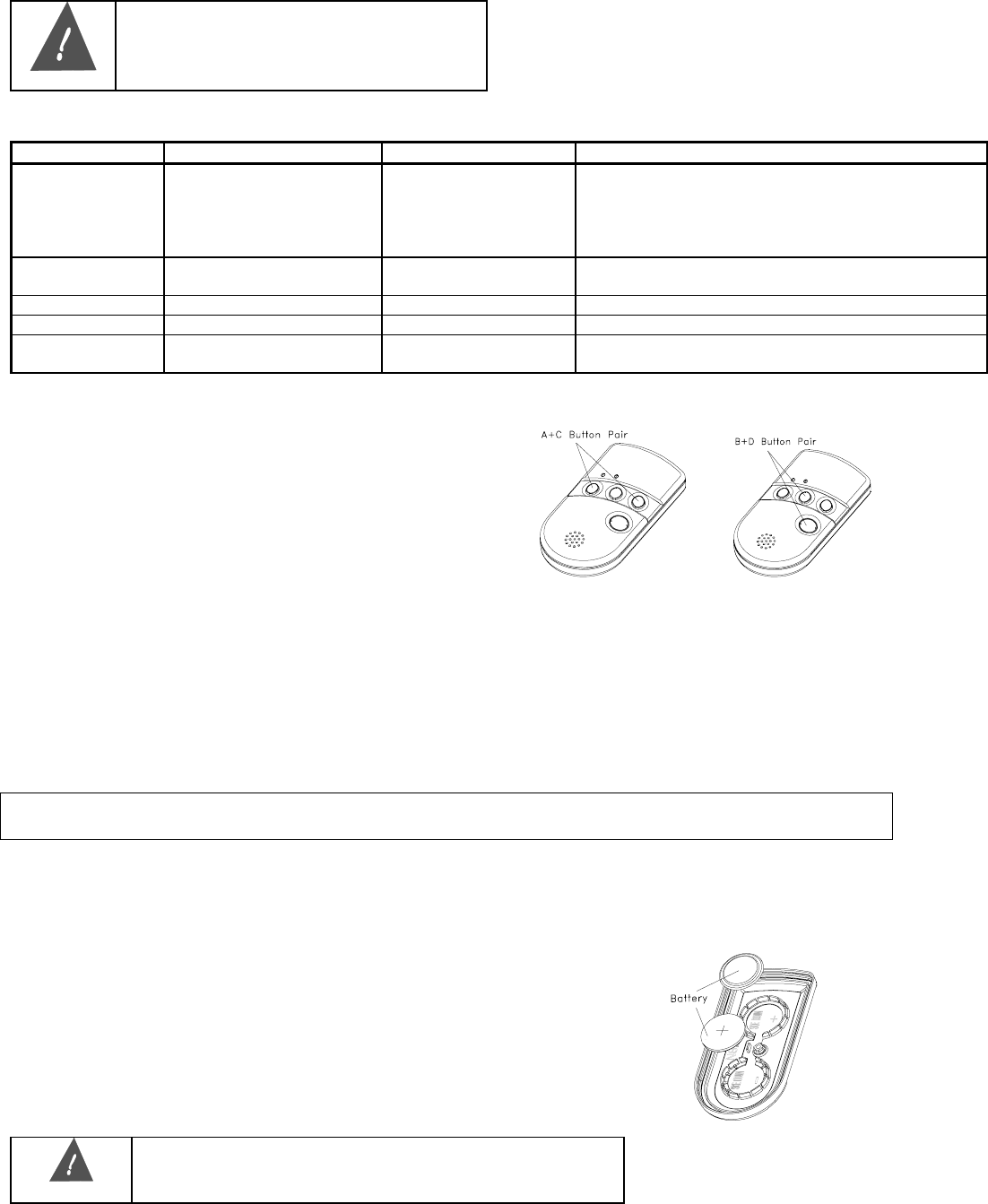
MULTIPLE BUTTON OPERATIONS
The 5804BD can generate the same responses as
keypad panic key pairs of [✶] + [#] and [✶] + [1] by
depressing “A” + “C” and “B” + “D” button pairs,
respectively. You must depress the button pair for at
least two seconds for the 5804BD to recognize the
button pair command. These button pairs allow the user
to activate panic, fire, and medical alarms depending on
control panel programming.
Failure of Replaceable Batteries
This wireless key has been designed to provide several years of battery life under normal conditions. The
expected battery life is a function of the device environment, usage and type. Ambient conditions such as high
humidity, high or low temperatures, or large temperature fluctuations may reduce the expected battery life.
This device will report a low battery condition to the control panel as a trouble condition, when the batteries
need to be replaced. In addition the yellow LED will not flash when a button is pressed. However, if the device
is unused for a long period of time, it may fail to operate as expected. Regular testing and maintenance will
keep the system in good operating condition for the lifetime of the product.
IMPORTANT! This wireless key is intended as a convenience to the user and should not be considered as a
life safety device. If life safety is important, please select a supervised wireless key (e.g. type 5802MN).
Low-Battery Indication
When the unit goes into a low battery condition, the yellow LED will not flash when a button is pressed.
Change both batteries immediately.
TO INSTALL / REPLACE BATTERIES
1. Remove the screw from the case back.
2. Remove case back by using the blade of a small screwdriver to pry open.
3. Place batteries in case back locations (see diagram). Use CR2430 or
DL2430 Lithium battery only.
4. Close the case by snapping case front and back together.
5. Replace the screw to secure the case.
WARNING!
Improperly installing the batteries will cause damage to the
batteries.
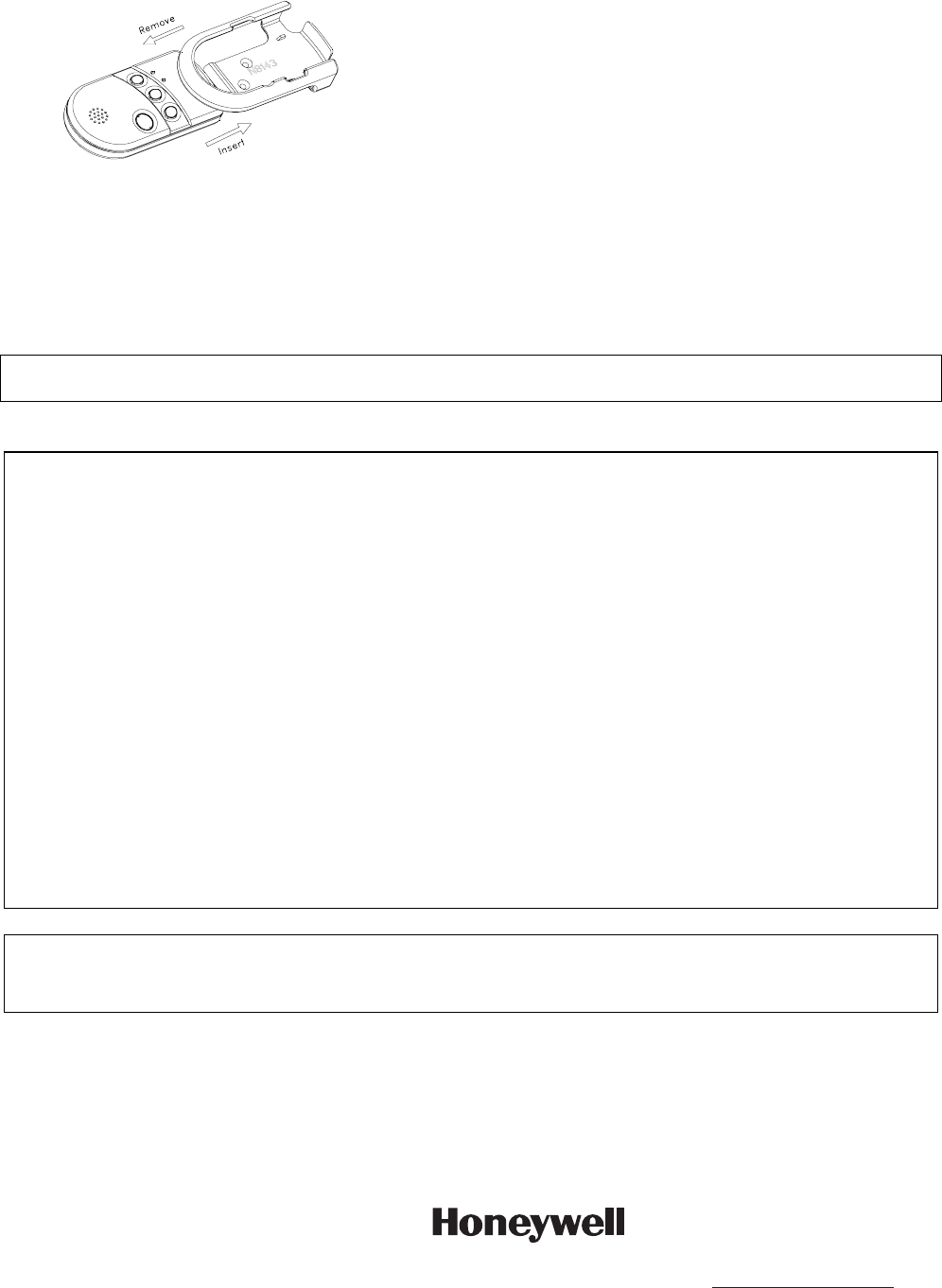
TO REMOVE OR INSERT THE UNIT FROM BELT CLIP
SPECIFICATIONS
Physical: Belt Clip: 4.1H x 2.2”W x 0.8”D
Transmitter: 3.9”H x 2.0”W x 0.69”D
Battery: Maxell CR2430 or Duracell DL2430
REFER TO THE INSTALLATION INSTRUCTIONS FOR THE CONTROL WITH WHICH THIS DEVICE IS USED FOR
LIMITATIONS OF THE ENTIRE ALARM SYSTEM.
FEDERAL COMMUNICATIONS COMMISSION (FCC) STATEMENTS
The user shall not make any changes or modifications to the equipment unless authorized by the Installation Instructions or User's
Manual. Unauthorized changes or modifications could void the user's authority to operate the equipment.
CLASS B DIGITAL DEVICE STATEMENT
NOTE: This equipment has been tested and found to comply with the limits for a Class B digital device, pursuant to part 15 of the FCC
Rules. These limits are designed to provide reasonable protection against harmful interference in a residential installation. This
equipment generates, uses and can radiate radio frequency energy and, if not installed and used in accordance with the instructions,
may cause harmful interference to radio communications. However, there is no guarantee that interference will not occur in a particular
installation. If this equipment does cause harmful interference to radio or television reception, which can be determined by turning the
equipment off and on, the user is encouraged to try to correct the interference by one or more of the following measures:
• Reorient or relocate the receiving antenna.
• Increase the separation between the equipment and receiver.
• Connect the equipment into an outlet on a circuit different from that to which the receiver is connected.
• Consult the dealer or an experienced radio/TV technician for help.
INDUSTRY CANADA (IC) STATEMENTS
This device complies with RSS210 of Industry Canada. Operation is subject to the following two conditions: (1) This device may not
cause harmful interference, and (2) This device must accept any interference received, including interference that may cause undesired
operation.
This Class B digital apparatus complies with Canadian ICES-003.
Cet appareil numérique de la classe B est conforme à la norme NMB-003 du Canada.
WARRANTY INFORMATION
For the latest warranty information, please go to:
http://www.security.honeywell.com/hsc/resources/wa/index.html
ÊN8209V1\Š
N8209V1 04/09 Rev. A
2 Corporate Center Drive, Suite 100
P.O. Box 9040, Melville, NY 11747
Copyright © 2009 Honeywell International Inc.
www.honeywell.com/security