Ademco 8DL5805BDV-1 Key fob Security Transceiver User Manual new srr fcc sub rev 1
Honeywell International Inc. Key fob Security Transceiver new srr fcc sub rev 1
UserManual.wiki
>
Ademco
>
8DL5805BDV 1 User Manual
II with FCC Part 15 statment
Navigation menu
Upload a User Manual
Namespaces
Wiki Guide
HTML
PDF
Info
Views
User Manual
Discussion / Help
Navigation
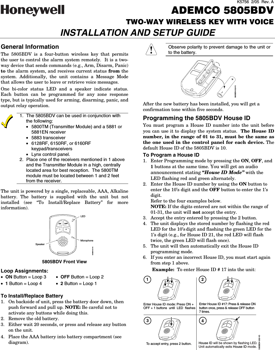
![- 2 - To View the House ID 1. Enter Programming mode as described in step 1 (previous page). 2. Depress the 2 button to view. The unit displays the stored number as programmed on the previous page (step 4), then automatically exits Programming mode. Programming a House ID in the Control Panel • On VISTA-40 control panels and above, use Device Programming mode to enable the RF receiver and enter the House ID number. • On VIA-30 control panels and below, go to field ✶24 and enter the House ID number. Programming the Buttons Each 5805BDV is assigned a unique serial number during manufacture. Each button on the unit also has a unique “loop” number that must be programmed into the control panel during installation. Assign each button to an individual zone number and program the Input Type as BR (Button Type RF) by entering 5 in the control panel’s Zone Programming mode. Then, input the serial number by one of the following methods: • Transmit twice from the device by pressing one of the buttons when prompted for the serial number. • Enter the serial number manually through the keypad. • Enter the serial number through Compass downloader software as applicable. Be sure to include the loop number of each button during programming (see loop assignments on previous page). NOTE: Do not use the 5805BDV for 24-hour silent alarm, as the unit itself is not silent. Button 1 If you choose not to use Button 1, you must do the following to avoid a “CHECK” condition when the button is accidentally pressed: 1. Assign this button to a zone. 2. After the serial number has been programmed, re-enter Zone Programming for that zone. 3. At the “Zone Type” prompt, enter 00 and press [✶]. a) On VIA-30 control panels and below, the system will ask whether you want to permanently delete that zone. Enter 0 (No). This will cause the system to retain the serial number, but render the button inactive. b) On VISTA-40 control panels and above, continue to press [✶] until you see the “Enter Zone No?” prompt again. At this point, Press 00 and [✶]. Then press ✶99 to exit Program mode. On VISTA-40 control panels and above If a button is assigned to zone type 20 (Arm Stay), 21 (Arm Away), or 22 (Disarm), you must assign a user to the button in order for it to operate. Proceed with the following steps. To assign a user number to an Arm/Disarm button: 1. Enter [4-digit User Code] + 8 + [User No.] + [4-digit new User Code]. 2. Answer Yes or No to the “Open/Close Report?” question. 3. Answer Yes to the “RF Button?” question. 4. Enter the zone number assigned to the Arm/Disarm button. The keypad will show the summary of user information on its display. 5. Test the Arm/Disarm button to make sure it operates correctly. Activating High-Security Mode In order to activate the 5805BDV wireless key in High-Security mode, you must use an encryption-capable 5800 Series receiver or transceiver. 1. Program the 5805BDV in Zone Programming mode as usual. 2. After programming the unit, exit Zone Programming mode. 3. Enter Go/No Go Test mode at the control panel (see the control panel Installation Instructions for specific information.) 4. Press and hold the ON, 1, and 2 buttons at the same time. You will get an audio announcement stating “Encrypted Mode On” with the LED flashing red and green alternately. 5. The 5805BDV transmits a special signal to the receiver. After 2 seconds, the unit will shut down. The 5805BDV is now in High-Security mode. Deactivating High-Security Mode Press and hold down the OFF, 1, and 2 buttons at the same time. You will get an audio announcement stating “Encrypted Mode Off” with the LED flashing red and green alternately. After 2 seconds the 5805BDV will shut down and is no longer in High-Security mode. Adjusting Volume Level This unit is shipped with the volume set to the lowest level. To adjust the volume, proceed as follows: 1. Enter the Volume Level Programming mode by pressing and holding down the ON, OFF, and 2 buttons simultaneously until the LED flashes red. NOTE: If no button is pressed for 5 seconds, the unit will automatically shut down and no change to the volume level is made. a. Press the 1 button for low volume level, or b. Press the ON button for medium volume level, or c. Press the OFF button for maximum volume level. The word “CHECK” will be heard for the volume level adjustment. 2. Press the 2 button to accept volume setting. Volume level setting affects the life of the battery. Use low volume for maximum battery life.](https://usermanual.wiki/Ademco/8DL5805BDV-1/User-Guide-518631-Page-3.png)
![- 3 - To Record a Message 1. Press and hold down the 1 and 2 buttons for two seconds. You will get an audio announcement of “Message Mode. NOTE: If the Red LED is flashing and you hear “Check Message,” there is a recorded message that must be played back before you can record a new message. 2. Press and release the ON button and begin speaking into the microphone if you want to record up to a 20-second message. To stop recording, press/release the OFF button. To Playback a Message 1. Press and hold down the 1 and 2 buttons for two seconds. You will get an audio announcement stating “Message Mode—Check Message” with the Red LED flashing. 2. Press and release the 2 button to playback the message. To Activate a Function To activate a function, press and hold down the appropriate button until a single beep is heard and the LED alternately flashes RED and GREEN, and then release. System Status Indications Table LED LED Condition Voice Announcement System Status System Armed Away Armed Away or Maximum On Steady System Armed Stay Armed Stay or Instant Fire, Zone (Faulted Zone Number or Zone Descriptor) * Fire Alarm in progress Alarm, Zone (Faulted Zone Number or Zone Descriptor) * Armed, Burglary Alarm in progress, or Alarm Memory Red Flashing In Set Volume Level Mode On Steady System Disarmed Ready To Arm Disarmed, Ready to Arm Green Flashing System Disarmed Not Ready To Arm System Not Ready, System Trouble Flashing Silent Indicates RF transmission In Programming Mode (Installer use) Red & Green Alternately Flashing Silent In Enable or Disable Encryption Mode * Zone descriptors will be annunciated only if the receiver is capable of sending zone descriptor information (e.g., 5883, 6160RF, Lynx – version 1.6 or higher). To Request System Status Because the 5805BDV is a two-way device, users can check the system status before arming or disarming their system. To check system status, press and release any button momentarily. A single beep is heard and the LED alternately flashes RED and GREEN. After a second or two, the 5805BDV will display and annunciate the system status (see the System Status Indications Table). If the 5805BDV does not receive system status information from the panel for approximately 5 seconds, it shuts itself down. It also shuts itself down if there is no button activity within 5 seconds of receiving a status update. If there is a message in the Lynx panel, an initiated status request causes the 5805BDV to annunciate “Console Message.” A message in the 5805BDV causes the annunciation of “Reminder Message.” If both units contain a message, both annunciations are generated. For example, “System Disarmed Ready to Arm”, “Console Message” and a beep will be heard followed by “Reminder Message.” NOTES: • If the Lynx panel contains a message and is armed, NO message is annunciated by the 5805BDV. • A new “Reminder Message” will annunciate whenever the 5805BDV gets status. This device may not receive the system status properly if it operates within a few feet of the 5881 or 5883 receiver. Low-Battery Indication When the unit goes into a low battery condition, its volume level will drop, and the LED will no longer flash when a button is pressed. However, the LED will still light to indicate status. Change the battery immediately. Refer to the instructions in the paragraph, “To Install/Replace Battery” on first page. Multiple Button Operations The 5805BDV should NOT be used for 24-hour silent alarm, as the unit itself is not silent. Also, it is recommended that the unit NOT be programmed for a one-button panic. The 5805BDV can generate the same responses as keypad panic key pairs of [1] + [✱] and [✱] + [#] by depressing ON + 1 and OFF + 2 button pairs, respectively. You must depress the button pair for at least 2 seconds for the 5805BDV to recognize the button pair command. These button pairs allow the user to activate panic, fire, and medical alarms depending on control panel programming. 5805BDV-004-V0OFF2ON1 Specifications Physical: Transmitter: 2.8” H x 1.8” W x 0.69” D Battery: 1.5VDC, AAA, Alkaline](https://usermanual.wiki/Ademco/8DL5805BDV-1/User-Guide-518631-Page-4.png)